Article

Thermal-Hydraulic Characteristics of Carbon Dioxide in Printed Circuit Heat Exchangers with Staggered Airfoil Fins

College of Power Engineering, Naval University of Engineering, Wuhan 430033, China
*
Author to whom correspondence should be addressed.
Processes 2023, 11(8), 2244; https://doi.org/10.3390/pr11082244
Submission received: 5 July 2023 / Revised: 19 July 2023 / Accepted: 21 July 2023 / Published: 26 July 2023
(This article belongs to the Special Issue Advances in Process Optimization and Control)

Abstract

:
Airfoil fin printed circuit heat exchangers (PCHEs) have broad application prospects in the naval, aerospace, electric power, and petrochemical industries. The channel structure is a critical factor affecting their thermal-hydraulic characteristics. In this study, a novel PCHE channel structure with staggered NACA 0025 airfoil-shaped fins was proposed; accordingly, the thermal-hydraulic characteristics of the novel channel structure using carbon dioxide as the working fluid at different fin heights under different operating conditions (trans-, near-, and far-critical) were investigated. The results indicated that the thermal-hydraulic performance of the PCHE under the trans-critical operating condition was better than that under the near-critical and far-critical operating conditions. Compared with conventional airfoil fin channels, the novel airfoil fin channel attained comparable comprehensive performance while reducing the fin volume by 50%, thus achieving a more lightweight PCHE design. The comprehensive performance of the PCHE was the poorest when the fin height was slightly below the channel height, which should be avoided during the design of airfoil fin PCHEs. The results provide theoretical support for the design and optimization of airfoil fin PCHEs.

Graphical Abstract

1. Introduction

Heat exchangers are widely used in the transportation, electric power, petroleum, and chemical industries. The performance of heat exchangers significantly affects the overall functionality and energy efficiency of these systems. Owing to the current dilemma between carbon emission reduction efforts to combat global warming and growing demand for energy, improving the thermal-hydraulic performance of heat exchangers has once again become a hot research topic.
Printed circuit heat exchangers (PCHEs) are a novel and compact class of heat exchangers. Figure 1 shows their typical structure [1,2]. PCHEs are compact [2] (the volume of a PCHE being approximately one sixth of that of a shell-and-tube heat exchanger capable of the same thermal load) and lightweight, can be easily modularized [3], have high heat transfer area density (up to 2500 m2/m3) [4] and high heat transfer efficiency (up to 98%) [5], and can work over a wide range of temperatures (working temperature of the core: −200–900 °C) and high pressures (working pressure of the working fluid: 60–115 MPa) [6]. The fluid channels of PCHEs are several millimeters in size, thus, having significant advantages over conventional heat exchangers in terms of heat transfer coefficient and efficiency. Currently, PCHEs have been widely used in waste heat recovery and cascade utilization [7,8], solar energy photo-thermal utilization [9,10], next-generation nuclear power heat-work conversion [11,12], and liquefied natural gas (LNG) regasification [13] with broad development prospects.
The channel structure of a PCHE is a critical factor affecting the thermal-hydraulic performance. PCHEs have two types of channel structures: continuous and embedded discrete-fin channels. Continuous channels can be straight [1,14,15], zigzagged [16,17,18], wavy [19,20], trapezoidal [21,22], or helical in shape [23]. Channels with discrete fins can have S-shaped [24] or airfoil fins. Straight channels have a simple structure but poor heat transfer performance. Zigzagged and wavy channels have better heat transfer performance but implement turns that cause flow separation and significant pressure loss. Discrete-fin channels, especially airfoil fin channels, have better comprehensive heat transfer performance compared to continuous channels [25,26,27,28].
Airfoil fins have good hydrodynamic performance. They are capable for disturbing the flow and enhancing heat transfer while avoiding the generation of significant vortexes and separation flows. Therefore, they effectively reduce the streamwise resistance loss and improve the thermal-hydraulic performance. The foil shape promoted by National Advisory Committee for Aeronautics (NACA) are usually used as the cross-sectional shapes of airfoil fins for investigating their effects on the thermal-hydraulic performance. Chen et al. [29] comparatively investigated PCHEs with fins modeled using four different NACA 00XX series airfoil geometries and found that the PCHE with the NACA 0010 airfoil fins exhibited the best overall performance. Tian et al. [30] investigated the comprehensive performance of PCHEs with eight different configurations using supercritical LNG as the working fluid and found that asymmetric fins had better heat transfer performance compared to symmetric fins. Wang et al. [31] investigated the effects of airfoil fin geometric parameters (curvature, position of the maximum curvature, and thickness) and their arrangement (horizontal and vertical spacings) on the thermo-hydraulic performance of a PCHE. Accordingly, they found that the airfoil fin thickness had the largest effect on the thermal-hydraulic performance, followed by the curvature and longitudinal spacing. Previous studies of airfoil fin channels focused on the cross-sectional geometry and arrangement parameters of airfoil fins, while few studies focused on the height of airfoil fins.
Researchers have attempted to improve the comprehensive performance of airfoil fin PCHEs by modifying the designs of NACA airfoils. Li et al. [32] proposed two slotted airfoil fins (longitudinal and herringbone slots) to reduce the effect of the impact area and found that the herringbone-slot fin attained a larger heat transfer area and better heat transfer performance. Cui et al. [33] modified the rear part of the NACA 0020 airfoil into a concave edge tangent to the maximum inscribed circle. Compared with the original design, the PCHE with the novel airfoil fin had better comprehensive performance and less entransy dissipation. Wang et al. [26] proposed a three-dimensional fin with variable cross-sections along the height direction that significantly reduced the impact area of the fluid and local flow resistance caused by the high velocity gradient, improving the comprehensive heat transfer performance. Xu et al. [34] proposed a novel fin that mimicked the shape of swordfish and effectively reduced the flow resistance. Attempts to optimize airfoil fin channels mainly focused on the cross-sectional geometry of fins, in which the fins were invariably designed equal to the channel height. Few attempts have been made to optimize the fin height.
The supercritical carbon dioxide (S-CO2) Brayton cycle (SCBC) has high power density and thermal efficiency; therefore, it is applicable to a wide range of heat sources [12] with a broad application prospect. PCHEs can be used as the heat exchange unit of an SCBC, significantly affecting the thermal efficiency of the cycle. Therefore, investigating the thermal-hydraulic characteristics of CO2 in PCHEs is of great significance. Existing studies focused on the effects of the cross-sectional geometry and streamwise arrangement of airfoil fins on the thermal-hydraulic characteristics, as well as design optimization. However, only a few studies focused on the height and height-direction arrangement of fins. For mobile platforms such as ships, the lightweight of equipment can effectively improve their maneuverability and endurance. As the largest amount of equipment in supercritical carbon dioxide power cycle, a heat exchanger is of great significance for its lightweight design. The height and height-direction arrangement of fins can affect the flow and heat transfer of CO2 in airfoil fin PCHE and the height of fins is closely related to the weight of PCHE. Therefore, this study proposed a novel PCHE channel structure with NACA airfoil-shaped fins staggered in the height direction and investigated the thermal-hydraulic performance of the novel channel structure using CO2 as the working fluid with different fin heights under different operating conditions. The results can provide theoretical support for the design and optimization of airfoil fin PCHEs.

2. Mathematical Model and Solution Methods
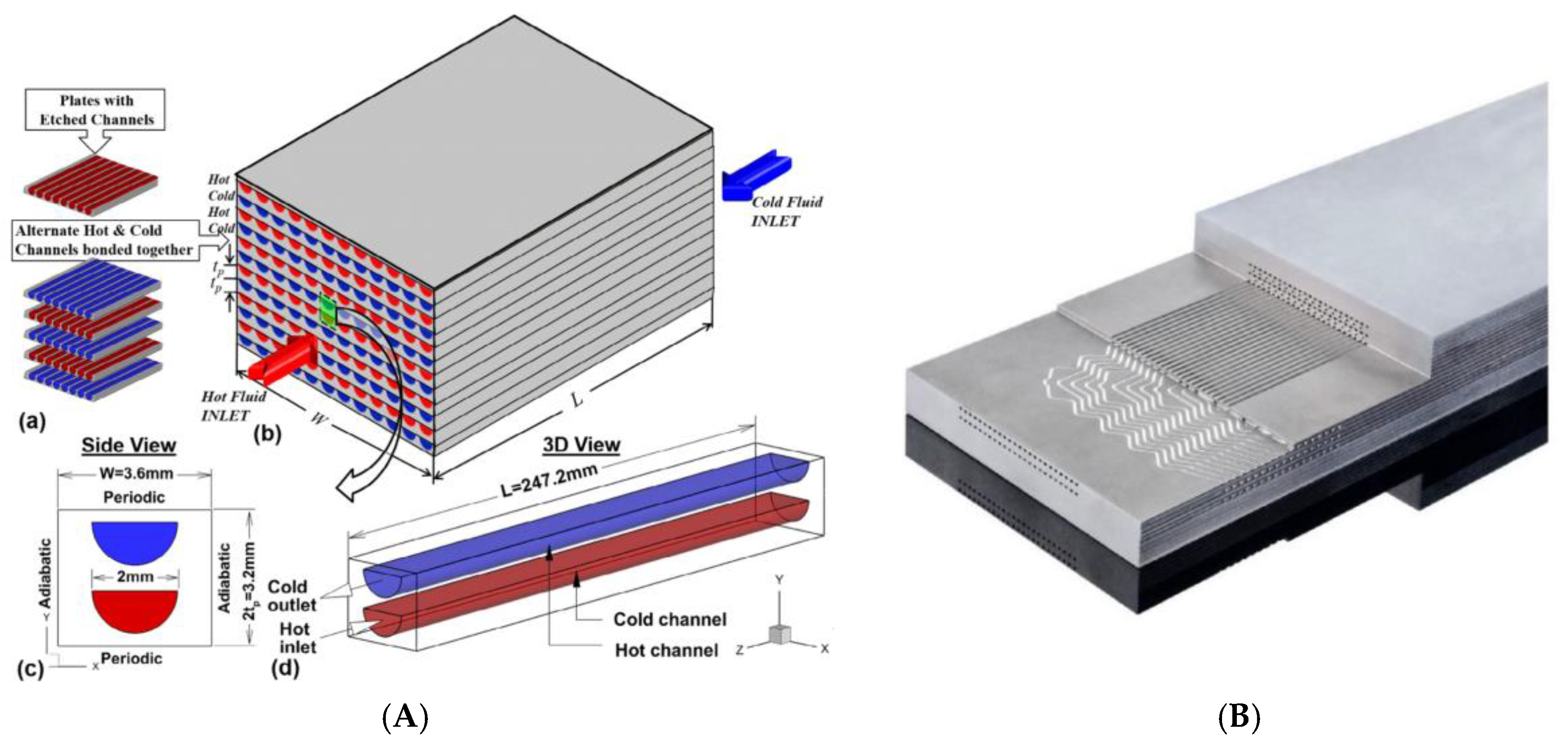
2.1. Gometric Model

A PCHE consists of many heat exchange channels, the structure of which significantly affects the overall PCHE performance. The NACA XYZZ airfoils have low flow resistance. In the airfoil designation, X represents the maximum camber in percent of the chord, Y represents the position of the maximum camber in tenths of the chord, and ZZ represents the maximum thickness in percent of the chord. Accordingly, in this study, a novel PCHE channel structure with the NACA 0025 airfoil-shaped fins staggered in the height direction was proposed. Figure 2 shows the geometric model of the novel channel structure.
The airfoil fins assumed the cross-sectional shape of the NACA 0025 airfoils, with a chord length L = 5 mm and height of H. They were staggered in the horizontal plane, with a longitudinal spacing of La = 2.5 mm and transverse staggering of Lb = 4 mm. The fins were also staggered in the height direction. Because the PCHE channel structure was highly symmetrical, the part depicted in the figure was selected for subsequent computations. To ensure accurate computations, the computational domain was extended to 20 mm beyond the inlet and outlet sections. The resulting computational domain was 140 mm long and 1.2 mm high, containing 30 airfoil fins.

2.2. Governing Equations and Boundary Conditions

The SST k-ω turbulence model was used. This model features near-wall stability and far-wall accuracy. The governing equations in the rectangular coordinate system can be expressed as follows:
Conservation of mass
( ρ u i ) x i = 0
Conservation of momentum
( ρ u i u j ) x i = p x i + [ ( μ + μ t ) ( u i x i + u j x j ) 2 3 ( μ + μ t ) u k x k ]
Conservation of energy
( ρ u i c p T ) x i = x i ( λ T x i ) + Φ
where x is the directions of the coordinate system (m), u is the velocity (m/s), p is the pressure (Pa), T is the temperature (K), ρ is the density (kg/m3), cp is the constant-pressure specific heat capacity (J/(kg·K)), μ is the dynamic viscosity (N·s/m2), λ is the thermal conductivity (W/(m·K)), μt is the turbulent viscosity (N·s/m2), and Φ is the viscosity-induced energy dissipation (W/m3).
The abovementioned governing equations were numerically solved using the Fluent software. The thermo-physical properties of S-CO2 were obtained using the NIST real gas model [20]. The boundary conditions of the computational domain were defined as follows. (1) Inlet: Mass flow inlet with fixed flow rate and temperature. The velocity is in the normal direction of the inlet. (2) Outlet: Pressure outlet. (3) Airfoil fin and top and bottom boundaries: The surface is defined as a non-slip wall with fixed temperature. (4) Left and right boundaries are symmetrical.
As shown in Figure 3, the physical properties of S-CO2 change drastically near the pseudo-critical point, which has a significant effect on the heat transfer process.
For a given pressure setpoint, three different operating conditions can be identified based on the difference from pseudo-critical temperatures, namely, far-critical, near-critical, and trans-critical [35].
The thermal-hydraulic performances of PCHE channels with different height airfoil fins under the three different prescribed operating conditions were investigated. Table 1 reports the parameter settings for the computational cases.

2.3. Performance Measures

The thermal-hydraulic performance of the novel channel structure using CO2 as the working fluid was evaluated based on the convective heat transfer coefficient, fanning friction factor, and comprehensive heat transfer performance evaluation criteria (PEC). The local parameters, designated using subscript L, in a series of cross-sections parallel to the YZ plane along the streamwise direction were computed and averaged as the respective overall parameters.
The local convective heat transfer coefficient is calculated as follows:
h L = q ˙ L T w , L T b , L
where hL is the cross-sectional convective heat transfer coefficient (W/(m2·K)), q ˙ L is the average boundary heat flux (W/m2), Tw,L is the wall temperature (K), and Tb,L is the average cross-sectional temperature (K).
The local Reynolds number (ReL) is calculated as follows:
R e L = ρ u L D h μ L
where ρ is the average cross-sectional density (kg/m3), uL is the average flow velocity (m/s), Dh is the Hydraulic diameter (m), and μL is the average dynamic viscosity (N·s/m2).
The local Nusselt number (NuL) is calculated as follows:
N u L = h L D h λ L
where λL is the average cross-sectional thermal conductivity (W/(m·K)).
The local Prandtl number (PrL) is calculated as follows:
P r L = μ L c P , L λ L
where cP,L is the average cross-sectional constant-pressure specific heat capacity (J/(kg·K)).
The local Colburn factor (jL) is calculated as follows [33]:
j L = N u L R e L P r L 1 / 3
The local fanning friction factor (fL) is calculated as follows [33]:
f L = ( p i n p L ) 2 u L 2 ρ L D h X L
where pin is the inlet pressure (Pa), pL is the cross-sectional pressure (Pa), and XL is the streamwise distance from the inlet to the cross-section (m).
The local PEC is calculated as follows:
P E C = j L f L 1 / 3

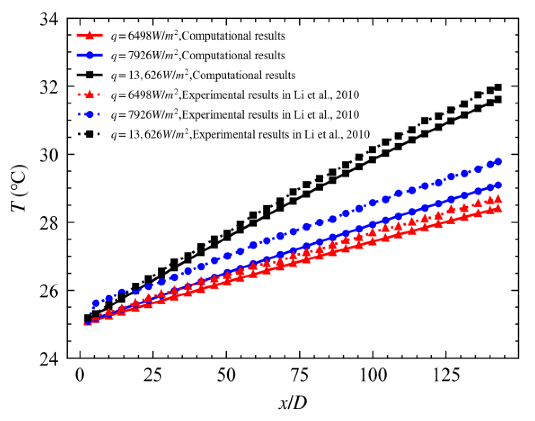
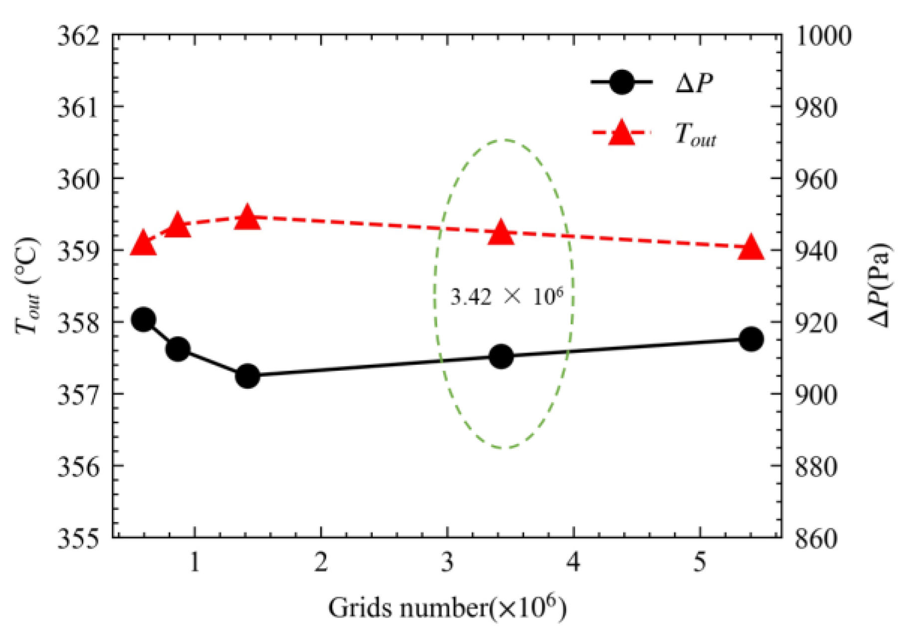
2.4. Verification of Numerical Results

Owing to the lack of experimental results in the literature regarding the CO2 thermal-hydraulic performance of airfoil fin channels, the accuracy of the computational method was verified first by comparing the numerical simulation results of the CO2 thermal-hydraulic of the airfoil fin channel to the those reported in reference [35] and then comparing the numerical simulation results of the CO2 thermal-hydraulic in a vertical straight circular tube to the experimental results reported in reference [36].
Simulations were performed using the same parameter settings used in reference [35]. The resulting h value used to represent the heat transfer behavior and f value used to represent the flow behavior were compared to those reported in reference [35], as shown in Figure 4. The maximum error of h was 2.24%, while that of f was 0.63%. The consistency of the results confirmed the reliability of the numerical computation methods proposed above.
A physical model of the experimental setup used in reference [36] was established, with the inner diameter of the vertical straight circular tube being 2 mm and height of the heat transfer section being 290 mm. The thermal-hydraulic in the circular tube with CO2 flowing upward in the tube were simulated under three different boundary conditions of heat flux, with the boundary conditions for the numerical simulations defined consistently with the experimental conditions. As shown in Figure 5, the streamwise variations in the average cross-sectional temperature at the three different heat fluxes obtained from the numerical simulations were consistent with the experimental results, with a maximum error of 2.34%.
This further confirmed the reliability of the numerical computation method proposed above.
To ensure the accuracy of computational results, the surface of the airfoil fin and top and bottom walls were meshed as shown in Figure 6. Figure 7 shows the results of mesh independence study.
When the number of cells reached 3.42 × 10⁶ as shown in the position of the green ellipse in Figure 7, the average outlet temperature and pressure drop varied by less than 0.6% as the number of cells continued to increase. Therefore, the effect of the number of cells on the computational results was negligible. Consequently, the computational domain was meshed using 3.42 × 10⁶ cells. This meshing scheme was maintained for all computational cases.

3. Results and Analysis

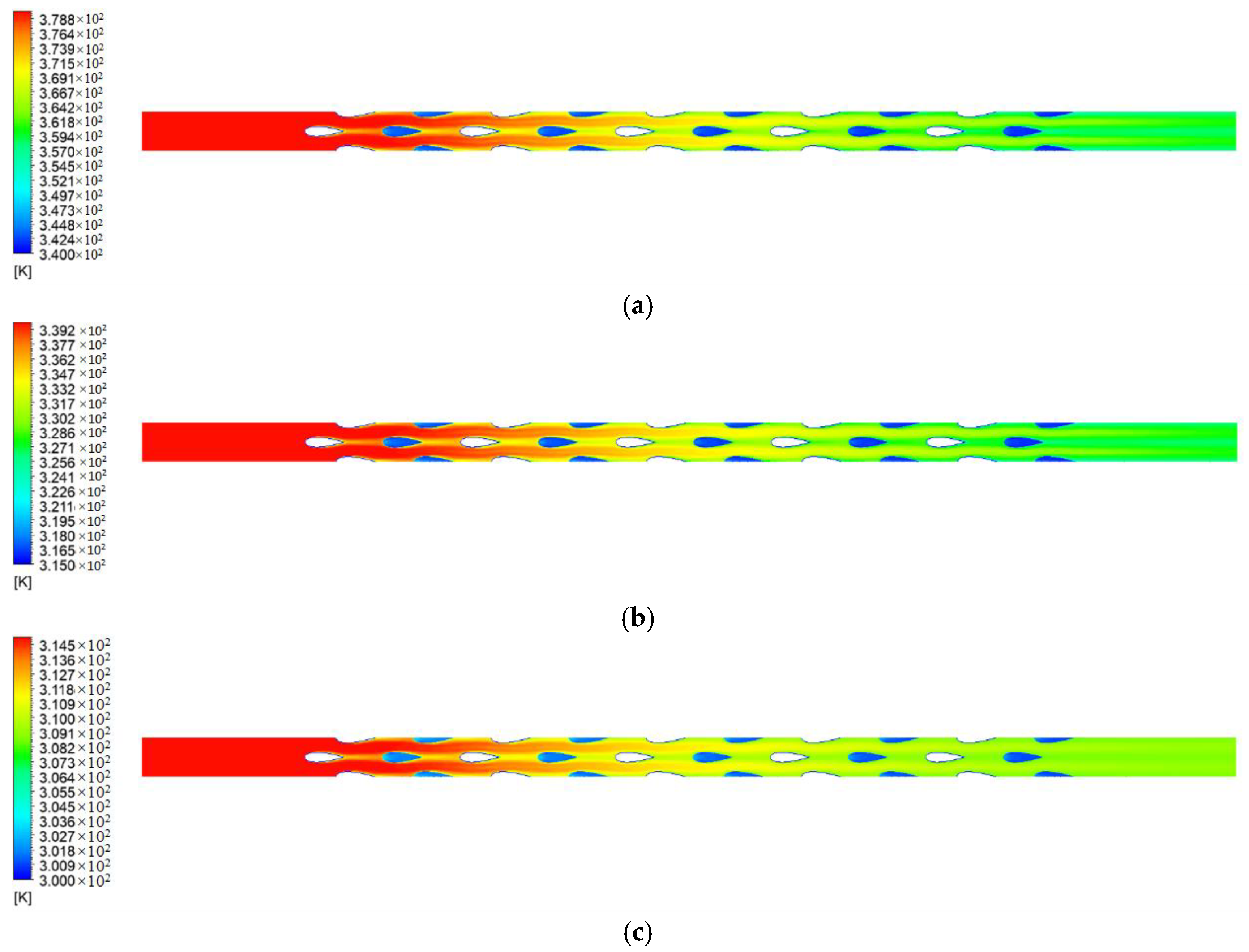
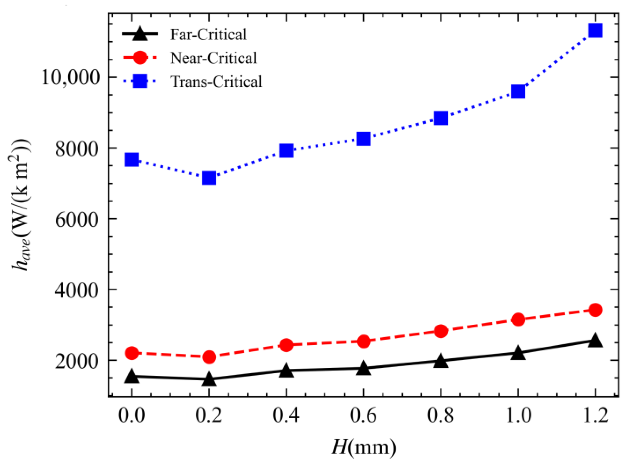
3.1. Analysis of Heat Transfer Characteristics

Figure 8 shows the variations in the heat transfer rate between the channel wall and fluid with respect to the fin height under the three different operating conditions. Q is the heat transfer rate. Under the three different operating conditions, the heat transfer rate of the channel with fins characterized by H = 0.6 mm increased 20.3% compared to that of the channel without fins but decreased by 20.1% compared with the channel with fins connected with both the top and bottom walls of the channel (connected fins). As the fin height increased from 0.2 mm to 1.0 mm, the heat transfer rate increased approximately linearly, and the magnitude of variation under the trans-critical operating condition was larger than that under the far-and near-critical operating conditions. As the fin height continued to increase from 1.0 mm to 1.2 mm, the variation in heat transfer rate abated, which was mainly due to the variations in the total heat transfer area.
Figure 9 shows the variations in the actual heat transfer area of the channel with respect to the fin height. A is the heat transfer area. For a channel with connected fins, the wall–fluid contact area decreased by the area of the suspended surface of the fins compared with a channel with unconnected fins. As H increased from 1.0 mm to 1.2 mm, the total heat transfer area (wall–fluid contact area) decreased by 6.0%.
Figure 10 shows the contours of the temperature for the channels without fins, with unconnected fins (H = 0.6 mm) and connected fins under the far-critical operating condition in the cross-section of Z = 0 (mid-channel height cross-section) with an inlet fluid temperature of 380 K. The streamwise fluid temperature variations were the largest in the channel with connected fins and smallest in the channel without fins. In addition, a comparison of the temperature fields in the channels with unconnected and connected fins showed that the high-temperature zones were concentrated in the transverse spacing between airfoil fins for the channel with unconnected fins but in the streamwise spacing between airfoil fins for the channel with connected fins.
Figure 11 shows the contours of the temperature in the cross-section of Z = 0 of the channel with unconnected fins (H = 0.6 mm) under the three different operating conditions. Despite the different inlet and wall temperatures, the streamwise temperature variations exhibited similar patterns, namely, high-temperature zones concentrating in the transverse spacing between airfoil fins. Additionally, the temperature variations in the tail region of the channel under the trans-critical operating condition were smaller than that observed under other operating conditions owing to the larger specific heat capacity of the fluid under the trans-critical operating condition.
Figure 12 shows the variations in the average convective heat transfer coefficient with respect to the fin height. The average convective heat transfer coefficient under the trans-critical operating condition was much higher than those under the far-critical and near-critical operating conditions, by 3.96 fold and 2.74 fold, respectively. The average convective heat transfer coefficient increased with the fin height; as the fin height increased from 0.2 mm to 1.0 mm, the average convective heat transfer coefficient increased approximately linearly. Under the three different operating conditions, the average convective heat transfer coefficient of the channel with unconnected fins (H = 0.6 mm) increased by a maximum of 14.8% compared with that of the channel without fins but deceased by a maximum of 30.8% compared with that of the channel with connected fins. As the fin height increased, the cross-sectional area of the fluid in the channel decreased. Consequently, for a given mass flow rate, the flow velocity increased, thus increasing the Reynolds number and enhancing convective hear transfer. When the fin height is relatively low, the effect of stirring the fluid and enhancing heat transfer is weak, and the overall heat transfer becomes worse due to the physical properties change. In particular in trans-critical conditions, the changes in physical parameters are severe, with the most significant decrease in convective heat transfer coefficient at H = 0.2 compared with the channel without fins.

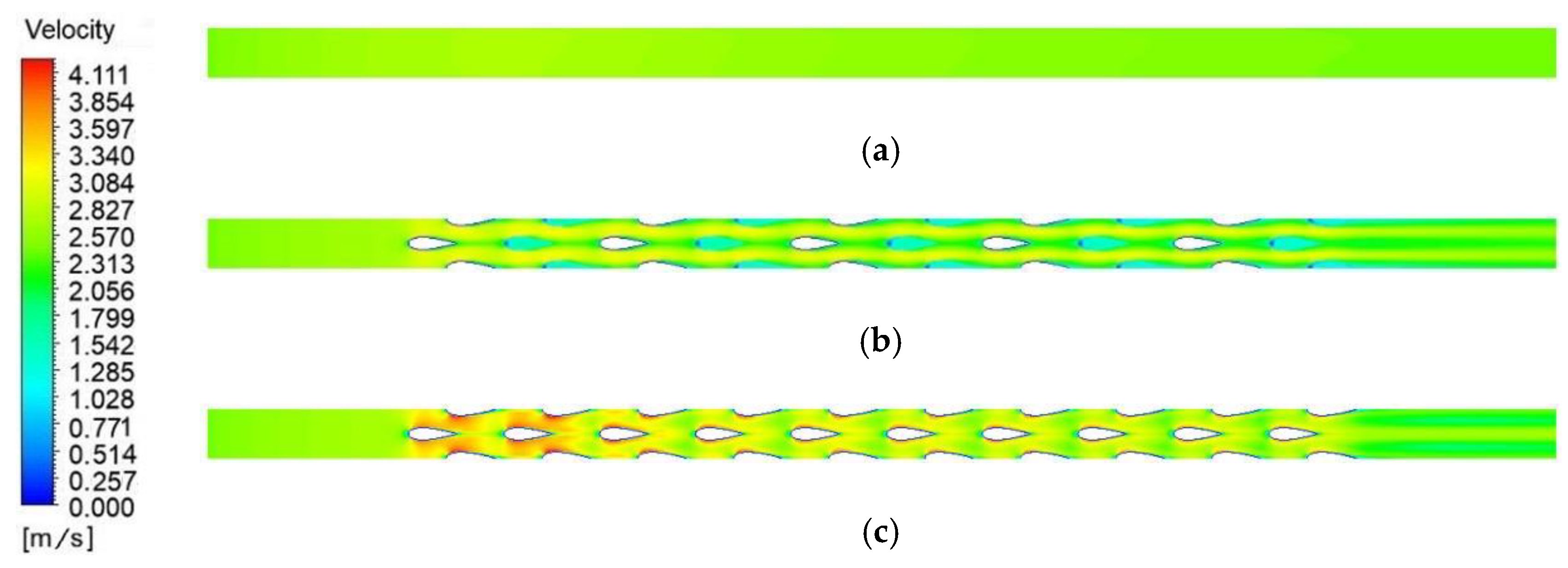
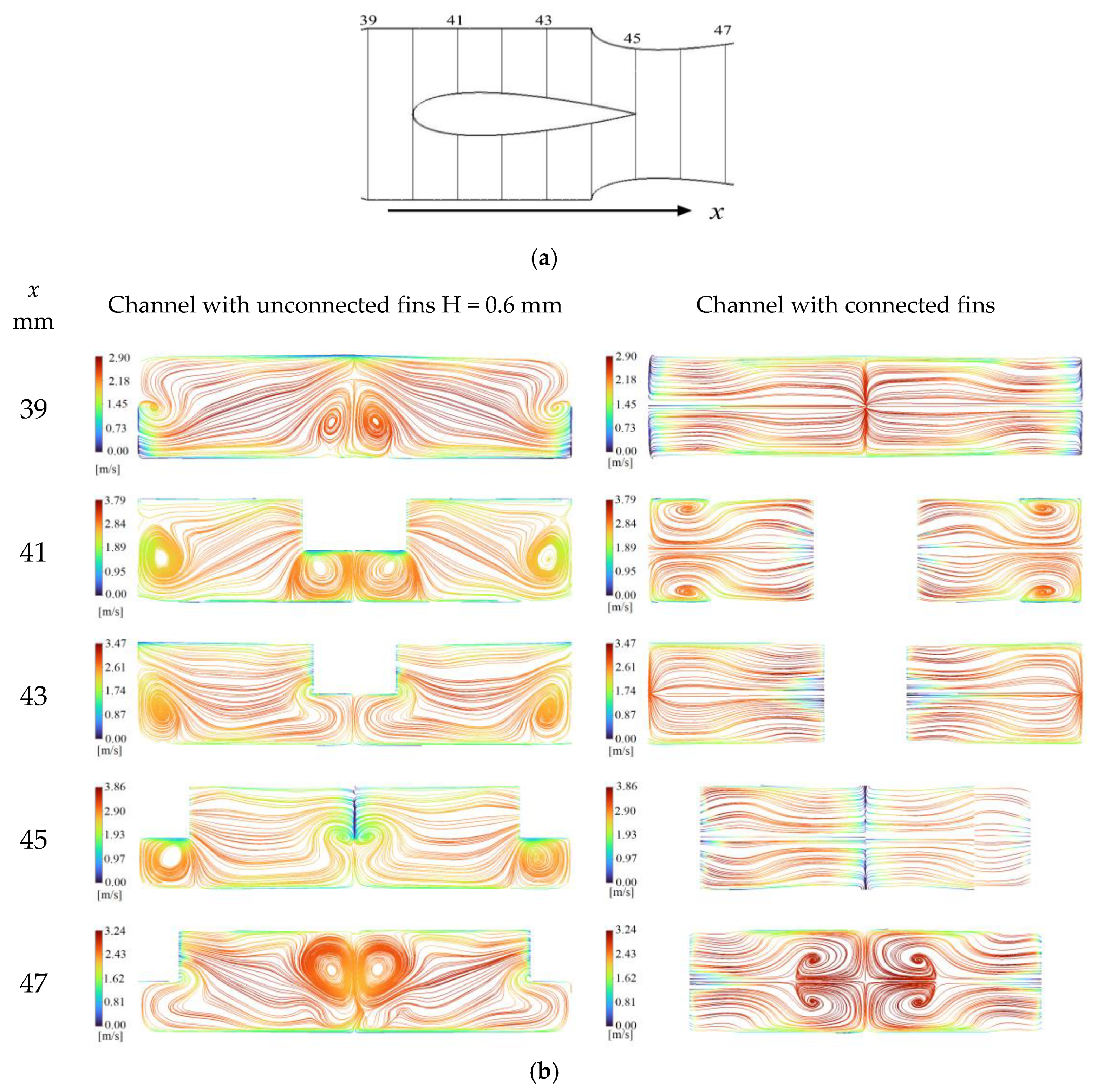
3.2. Analysis of Flow Characteristics

Figure 13 shows the contours of the pressure in the cross-section of Z = 0 of the channels with different fin heights under the far-critical operating condition at an outlet pressure of 8.0 MPa. The channel with connected fins had the highest inlet pressure, with a local pressure peak at the upstream end of each fin and low pressure areas on the two sides of the airfoil.
Figure 14 shows the variations in the inlet-outlet pressure drop of the channels with different fin heights under different operating conditions. As the fin height increased from 0 mm to 1.0 mm, the pressure drop increased. Increasing the fin height decreased the cross-sectional area of the channel and, for a given mass flow rate, increased the flow velocity, thus, increasing the pressure loss. Additionally, increasing the fin height increased the fluid-wall contact area, thus, also increasing the pressure loss. However, as the fin height increased from 1.0 mm to 1.2 mm, the wall surface area decreased; accordingly, the pressure loss decreased as well. A comparison of the pressure drop rates under the three different operating conditions showed that the pressure drop was the largest under the far-critical operating condition and smallest under the trans-critical operating condition. This was mainly because of the different densities and viscosity induced by the different temperatures implemented at the different operating conditions. As shown in Figure 3, the density increased as the temperature increased, and the viscosity increased as the temperature continued to increase from the pseudo-critical temperature. As the average fluid temperature increased under any of the operating conditions, the density decreased, viscosity increased, and, for a given mass flow rate, flow velocity increased, thus increasing the pressure loss.
Figure 15 shows contours of the velocity magnitude in the cross-section of Z = 0 under the far-critical operating condition. Owing to the different cross-sectional areas of the channels, the average cross-sectional velocity was the largest in the channel with connected fins and smallest in the channel without fins. For the channel with connected fins, the velocity field exhibited a local minimum at the upstream end of each fin (the location of which roughly corresponded to the local maximum of the pressure field), near-wall high-velocity zones on the two sides of the fins, and low-velocity zones in the streamwise spacing between fins. For the channel with unconnected fins, the velocity field exhibited low-velocity zones along the central lines of the fins and large-velocity zones in the transverse spacing between fins.
Figure 16a illustrates the cross-sections selected along the streamwise direction. Figure 16b shows the streamlines in the different cross-sections. Observe from the streamlines, different fin heights led to significantly different locations and morphologies of vortex flows. For the channel with unconnected fins, vortex flows occurred near the side walls (far regions of the fin) and near the suspended surface of the fins. For the channel with connected fins, because both the upper and lower surfaces of the fin were connected with the channel wall and only the lateral sides of the fins were in contact with the fluid, vortex flows occurred only in the far regions of the fin. Additionally, the flow velocity around the fins of the channel with unconnected fins was generally smaller than that of the channel with connected fins.
Figure 17 shows the streamlines in the mid-channel height cross-section, where the fluid flows around the leading edge of the airfoil on both sides, and the flow velocity increases while flow cross-section decreases. Figure 18 shows the streamlines in the mid-channel width cross-section, and it can be observed that when the fins are not fully penetrated, the fluid not only flows around the leading edge of the fin on both sides, but also flows towards the opposite side near the top of the fin in the height direction, forming a zig zag flow pattern.
Figure 19 shows the variations in the average fanning friction factor (fave) with respect to the fin height. The fave value was the largest under the trans-critical condition, and the fave values under the far-critical and near-critical conditions differed slightly. This could be explained by the different physical properties of CO2 under the different operating conditions (Figure 3), namely the physical properties of CO2 under the far-critical and near-critical operating conditions differed slightly compared to each other but differed considerably compared to those observed under the trans-critical operating condition. As the fin height increased form 0 mm to 1.0 mm, fave increased. As the fin height continued to increase from 1.0 mm to 1.2 mm, fave decreased. This was mainly due to the variations in the fluid-wall contact area with the fin height, which were similar to the variations in the total wall surface area with the fin height shown in Figure 9.

3.3. Analysis of Comprehensive Performance

Figure 20 shows the variations in the comprehensive performance (PEC) with respect to the fin height. As the fin height increased from 0 mm to 1.0 mm, PEC decreased and reached a minimum at H = 1.0 mm. However, as the fin height continued to increase from 1.0 mm to 1.2 mm, PEC increased. The PEC value was the largest under the trans-critical operating condition and smallest under the far-critical operating condition. The PEC value under the trans-critical operating condition increased by a maximum of 98.5% compared with the near-critical operating condition and 137.2% compared with the far-critical operating condition. The channels with unconnected fins which height is 0.6 mm and connected fins differed slightly in PEC, with a maximum relative difference of 3.2%.
Compared with the channel with connected fins, the channel with unconnected fins which height is 0.6 mm attained a comparable comprehensive performance but reduced the volume of fins by 50%. Therefore, it required less metal material for manufacturing and achieved a more lightweight PCHE design desirable for ships and other weight-sensitive applications. Under any of the three operating conditions, the PEC value was the lowest at a fin height of 1.0 mm. Hence, the design of PCHEs should avoid a fin height that is extremely close to the channel height.

4. Summary

In this study, a novel PCHE channel structure incorporating the NACA 0025 airfoil-shaped fins staggered in the height direction was proposed. Subsequently, the thermal-hydraulic performance of the novel channel structure using CO2 as the working fluid at different fin heights under different operating conditions were investigated. The major conclusions are summarized as follows.
(1)
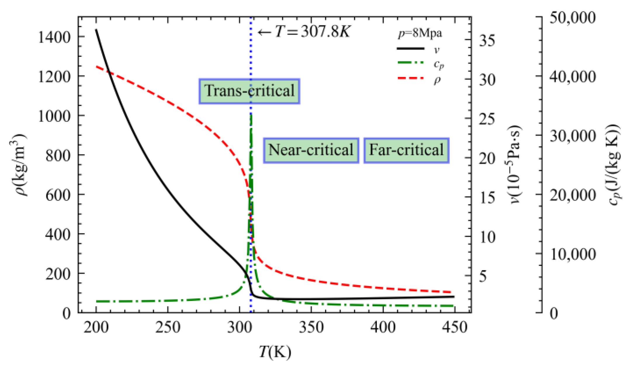
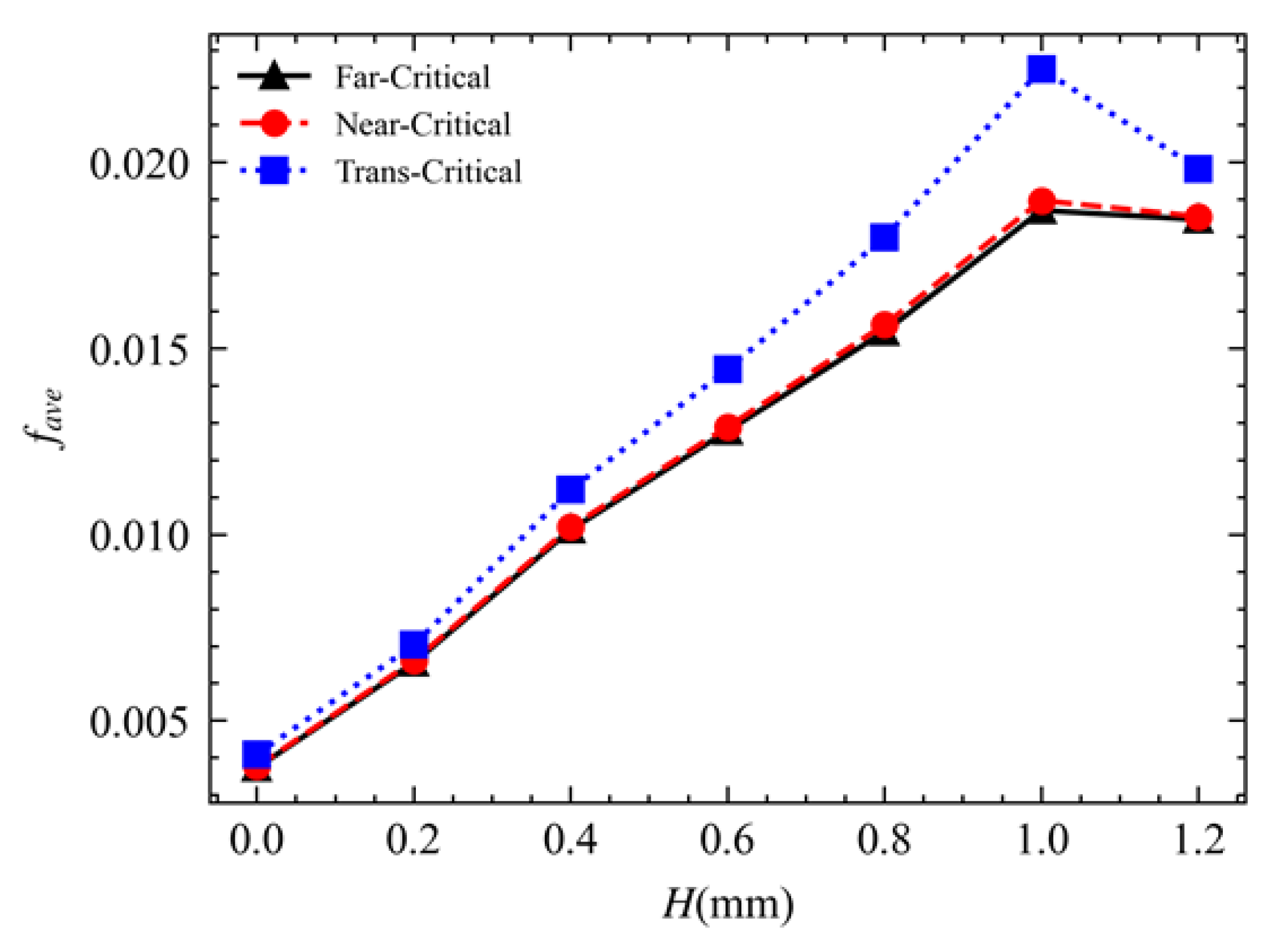
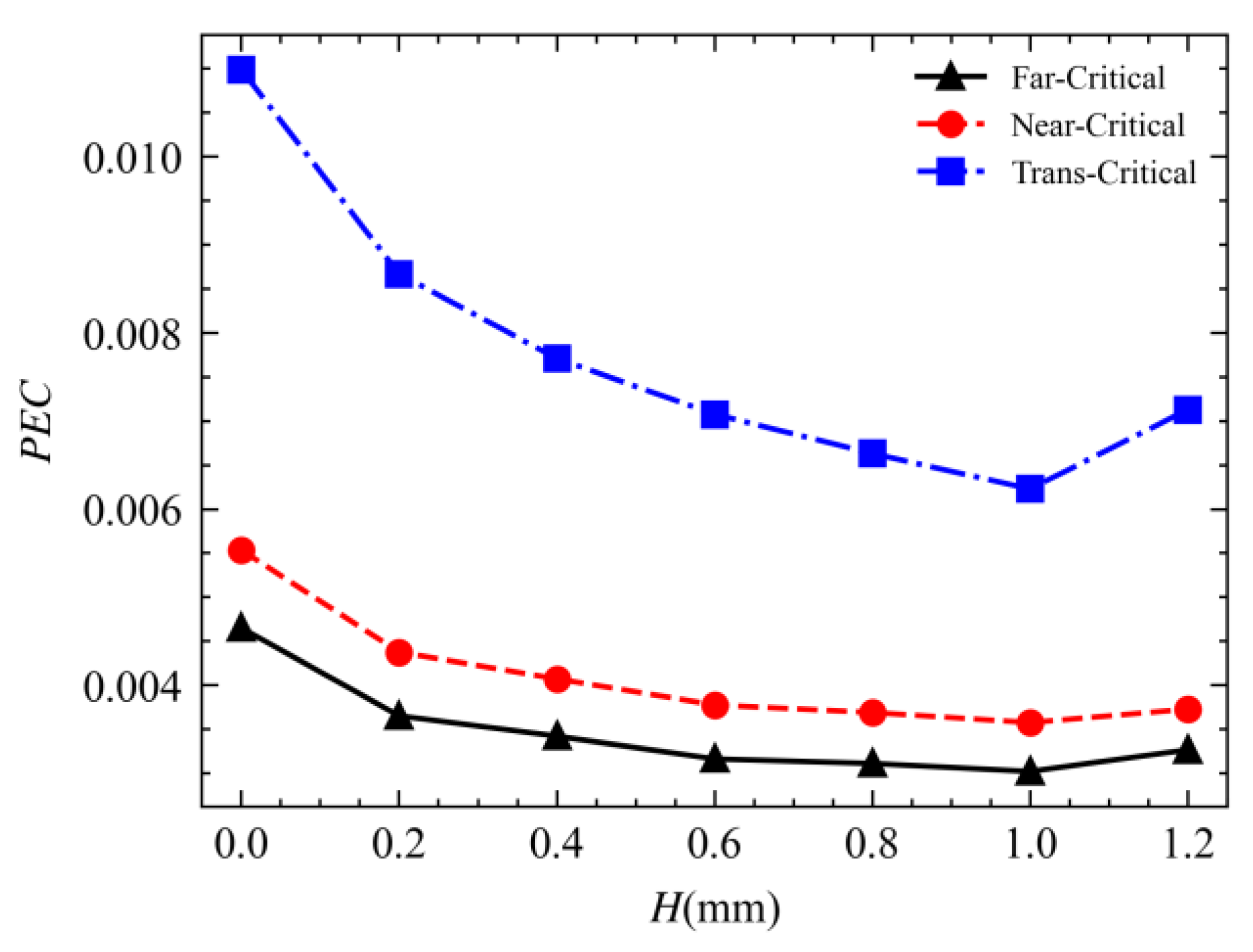
The convective heat transfer coefficient was the largest under the trans-critical operating condition, 3.96-fold higher than that observed under the far-critical operating condition and 2.74-fold higher than that observed under the near-critical operating condition. The trans-critical operating condition contributed to a larger fanning friction factor, higher density, lower flow velocity, and lower inlet-out pressure drop than those of the far-critical and near-critical operating conditions. The trans-critical operating condition yielded the best comprehensive performance.
(2)
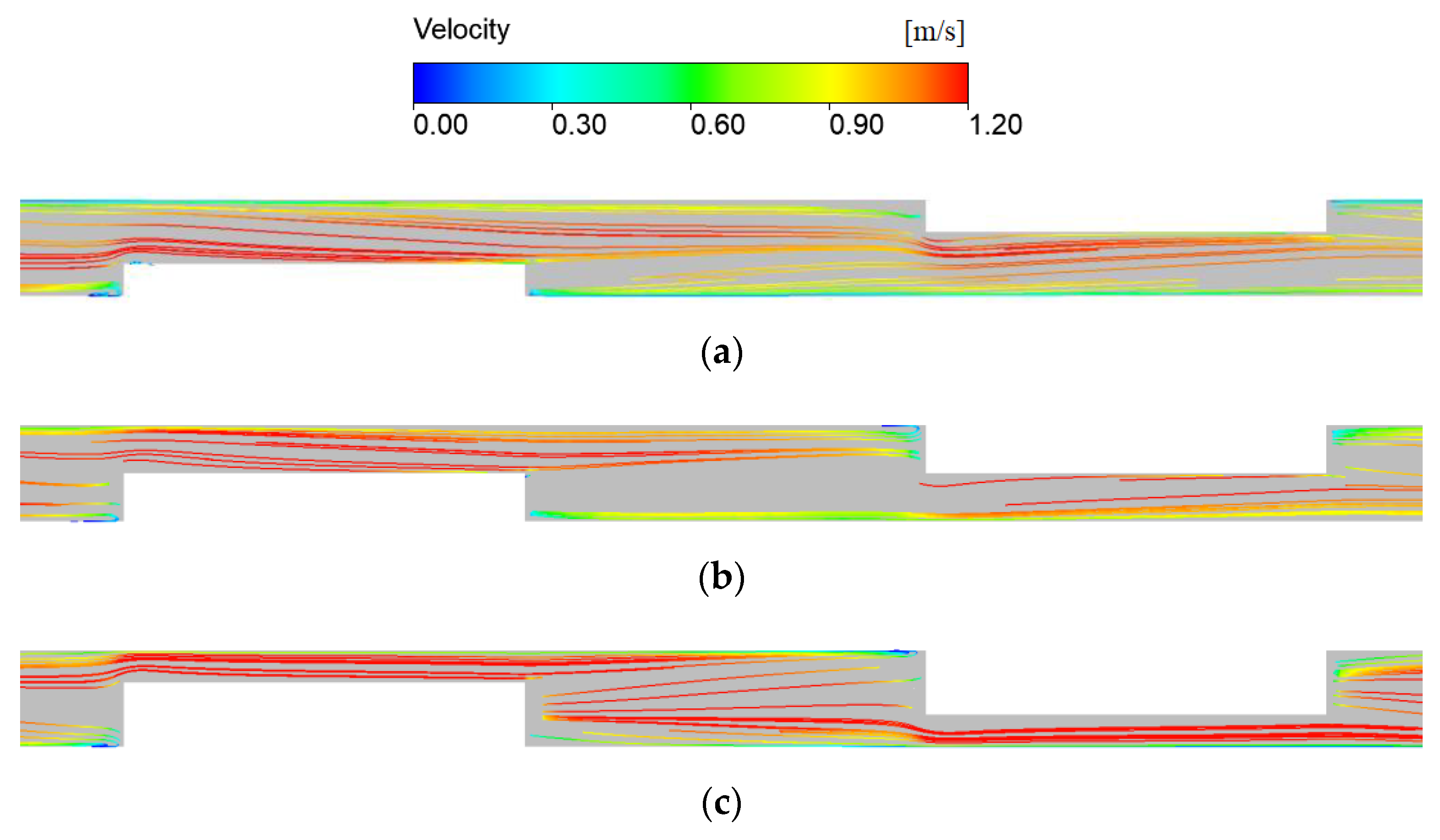
As the fin height increased, the cross-sectional area of the channel decreased, flow velocity increased, heat transfer enhanced, and pressure loss increased. Fin height significantly affected the occurrence position and morphology of vortex flows in the transverse cross-sections of the channel.
(3)
Compared with the channel with connected fins, the channel with unconnected fins which height is 0.6 mm attained a comparable comprehensive performance but reduced the volume of fins by 50%. Therefore, it achieved a more lightweight PCHE design. The thermo-hydraulic performance was the poorest when the fin height was extremely close to the channel height, which should be avoided during the design of airfoils for PCHEs.

Author Contributions

Conceptualization, K.X.; Methodology, X.Z., Z.X., F.M., Z.L. and X.J.; Software, K.X. and X.Z.; Validation, K.X., X.Z. and F.M.; Formal analysis, Z.L.; Investigation, K.X., X.Z., Z.X. and X.J.; Data curation, K.X. and X.Z.; Writing—original draft, K.X.; Writing—review & editing, Z.X.; Visualization, K.X., X.Z. and F.M.; Supervision, Z.X.; Project administration, Z.X.; Funding acquisition, Z.X. All authors have read and agreed to the published version of the manuscript.

Funding

This research was funded by the National Natural Science Foundation of China (grant numbers 51979278 and 51579244).

Data Availability Statement

Data will be made available on request.

Conflicts of Interest

The authors declare that they have no known competing financial interest or personal relationships that could have appeared to influence the work reported in this paper.

References

  1. Aneesh, A.M.; Sharma, A.; Srivastava, A.; Vyas, K.; Chaudhuri, P. Thermal-hydraulic characteristics and performance of 3D straight channel based printed circuit heat exchanger. Appl. Therm. Eng. 2016, 98, 474–482. [Google Scholar] [CrossRef]
  2. Chai, L.; Tassou, S.A. A review of printed circuit heat exchangers for helium and supercritical CO2 Brayton cycles. Therm. Sci. Eng. Prog. 2020, 18, 100543. [Google Scholar] [CrossRef]
  3. Huang, C.; Cai, W.; Wang, Y.; Liu, Y.; Li, Q.; Li, B. Review on the characteristics of flow and heat transfer in printed circuit heat exchangers. Appl. Therm. Eng. 2019, 153, 190–205. [Google Scholar] [CrossRef]
  4. Ma, T.; Li, M.J.; Xu, J.L.; Cao, F. Thermodynamic analysis and performance prediction on dynamic response characteristic of PCHE in 1000 MW S-CO2 coal fired power plant. Energy 2019, 175, 123–138. [Google Scholar] [CrossRef]
  5. Figley, J.; Sun, X.; Mylavarapu, S.K.; Hajek, B. Numerical study on thermal hydraulic performance of a Printed Circuit Heat Exchanger. Prog. Nucl. Energy 2013, 68, 89–96. [Google Scholar] [CrossRef]
  6. Saranam, V.R.; Paul, B.K. Feasibility of Using Diffusion Bonding for Producing Hybrid Printed Circuit Heat Exchangers for Nuclear Energy Applications. Procedia Manuf. 2018, 26, 560–569. [Google Scholar] [CrossRef]
  7. Mohammed, R.H.; Alsagri, A.S.; Wang, X. Performance improvement of supercritical carbon dioxide power cycles through its integration with bottoming heat recovery cycles and advanced heat exchanger design: A review. Int. J. Energy Res. 2020, 44, 7108–7135. [Google Scholar] [CrossRef]
  8. Marchionni, M.; Bianchi, G.; Tassou, S.A. Review of supercritical carbon dioxide (sCO2) technologies for high-grade waste heat to power conversion. SN Appl. Sci. 2020, 2, 611. [Google Scholar] [CrossRef] [Green Version]
  9. Ma, Y.; Xie, G.; Hooman, K. Review of printed circuit heat exchangers and its applications in solar thermal energy. Renew. Sustain. Energy Rev. 2021, 155, 111933. [Google Scholar] [CrossRef]
  10. Wang, K.; He, Y.L.; Zhu, H.H. Integration between supercritical CO2 Brayton cycles and molten salt solar power towers: A review and a comprehensive comparison of different cycle layouts. Appl. Energy 2017, 195, 819–836. [Google Scholar] [CrossRef]
  11. Wu, P.; Ma, Y.; Gao, C.; Liu, W.; Shan, J.; Huang, Y.; Wang, J.; Zhang, D.; Ran, X. A review of research and development of supercritical carbon dioxide Brayton cycle technology in nuclear engineering applications. Nucl. Eng. Des. 2020, 368, 110767. [Google Scholar] [CrossRef]
  12. Ahn, Y.; Bae, S.J.; Kim, M.; Cho, S.K.; Baik, S.; Lee, J.I.; Cha, J.E. Review of supercritical CO2 power cycle technology and current status of research and development. Nucl. Eng. Technol. 2015, 47, 647–661. [Google Scholar] [CrossRef] [Green Version]
  13. Baek, S.; Hwang, G.; Jeong, S.; Kim, J. Development of compact heat exchanger for LNG FPSO. In Proceedings of the Twenty-First International Offshore and Polar Engineering Conference, Maui, HI, USA, 19–24 June 2011. [Google Scholar]
  14. Zhao, Z.; Zhang, X.; Zhao, K.; Jiang, P.; Chen, Y. Numerical investigation on heat transfer and flow characteristics of supercritical nitrogen in a straight channel of printed circuit heat exchanger. Appl. Therm. Eng. 2017, 126, 717–729. [Google Scholar] [CrossRef]
  15. Sarmiento, A.P.C.; Milanez, F.H.; Mantelli, M.B.H. Theoretical models for compact printed circuit heat exchangers with straight semicircular channels. Appl. Therm. Eng. 2020, 184, 115435. [Google Scholar] [CrossRef]
  16. Xie, J.Y.; Chueh, C.C.; Chen, W.H.; Chen, K. Heat transfer performance comparison of printed circuit heat exchangers with straight, zigzag and serpentine flow channels for waste heat recovery. Int. J. Energy Res. 2021, 46, 1722–1735. [Google Scholar] [CrossRef]
  17. Bennett, K.; Chen, Y.T. Thermal-hydraulic correlations for zigzag-channel PCHEs covering a broad range of design parameters for estimating performance prior to modeling. Therm. Sci. Eng. Prog. 2019, 17, 100383. [Google Scholar] [CrossRef]
  18. Zhang, H.; Guo, J.; Huai, X.; Cheng, K.; Cui, X. Studies on the thermal-hydraulic performance of zigzag channel with supercritical pressure CO2. J. Supercrit. Fluids 2019, 148, 104–115. [Google Scholar] [CrossRef]
  19. Baik, Y.J.; Jeon, S.; Kim, B.; Jeon, D.; Byon, C. Heat transfer performance of wavy-channeled PCHEs and the effects of waviness factors. Int. J. Heat Mass Transf. 2017, 114, 809–815. [Google Scholar] [CrossRef]
  20. Wen, Z.X.; Lv, Y.G.; Li, Q.; Zhou, P. Numerical study on heat transfer behavior of wavy channel supercritical CO2 printed circuit heat exchangers with different amplitude and wavelength parameters. Int. J. Heat Mass Transf. 2019, 147, 118922. [Google Scholar] [CrossRef]
  21. Ji, Y.; Xing, K.; Cen, K.; Ni, M.; Xu, H.; Xiao, G. Numerical Study on Flow and Heat Transfer Characteristics of Trapezoidal Printed Circuit Heat Exchanger. Micromachines 2021, 12, 1589. [Google Scholar] [CrossRef]
  22. Aneesh, A.M.; Sharma, A.; Srivastava, A.; Chaudhury, P. Effects of wavy channel configurations on thermal-hydraulic characteristics of Printed Circuit Heat Exchanger (PCHE). Int. J. Heat Mass Transf. 2018, 118, 304–315. [Google Scholar] [CrossRef]
  23. Li, Y.; Qiu, Z.; Cui, D.; Wang, Z.; Zhang, J.; Ji, Y. Numerical investigation on the thermal-hydraulic performance of helical twine printed circuit heat exchanger. Int. Commun. Heat Mass Transf. 2021, 128, 105596. [Google Scholar] [CrossRef]
  24. Saeed, M.; Kim, M.H. Thermal-hydraulic analysis of sinusoidal fin-based printed circuit heat exchangers for supercritical CO2 Brayton cycle. Energy Convers. Manag. 2019, 193, 124–139. [Google Scholar] [CrossRef]
  25. Jin, F.; Chen, D.; Hu, L.; Huang, Y.; Zeng, H.; Wang, J. Thermo-Hydraulic performance of printed circuit heat exchanger as precooler in supercritical CO2 Brayton cycle. Appl. Therm. Eng. 2022, 210, 118341. [Google Scholar] [CrossRef]
  26. Wang, K.; Zhang, X.Y.; Zhang, Z.D.; Min, C.H. Three-dimensional shape optimization of fins in a printed circuit recuperator using S-CO2 as the heat-transfer fluid. Int. J. Heat Mass Transf. 2022, 192, 122910. [Google Scholar] [CrossRef]
  27. Chu, W.X.; Li, X.H.; Ting, M.; Zeng, M.; Wang, Q.W. Heat transfer and pressure drop performance of printed circuit heat exchanger with different fin structures. Chin. Sci. Bull. 2017, 62, 1788–1794. (In Chinese) [Google Scholar] [CrossRef]
  28. Xu, X.Y.; Wang, Q.W.; Li, L.; Ekkad, S.V.; Ma, T. Thermal-Hydraulic Performance of Different Discontinuous Fins Used in a Printed Circuit Heat Exchanger for Supercritical CO2. Numer. Heat Transf. Part A Appl. 2015, 68, 1067–1086. [Google Scholar] [CrossRef]
  29. Chen, F.; Zhang, L.; Huai, X.; Li, J.; Zhang, H.; Liu, Z. Comprehensive performance comparison of airfoil fin PCHEs with NACA 00XX series airfoil. Nucl. Eng. Des. 2017, 315, 42–50. [Google Scholar] [CrossRef]
  30. Tian, Y.; Long, C.; Tang, L. Study on Thermal-Hydraulic Performance of The Printed Circuit Heat Exchanger with Airfoil Fins for Supercritical Liquefied Natural Gas. Front. Heat Mass Transf. 2022, 19, 1–11. [Google Scholar] [CrossRef]
  31. Wang, W.; Ding, L.; Han, F.; Shuai, Y.; Li, B.; Sunden, B. Parametric Study on Thermo-Hydraulic Performance of NACA Airfoil Fin PCHEs Channels. Energies 2022, 15, 5095. [Google Scholar] [CrossRef]
  32. Li, X.L.; Tang, G.H.; Fan, Y.H.; Yang, D.L.; Wang, S.Q. Numerical Analysis of Slotted Airfoil Fins for Printed Circuit Heat Exchanger in S-CO2 Brayton Cycle. J. Nucl. Eng. Radiat. Sci. 2019, 5, 041303. [Google Scholar] [CrossRef]
  33. Cui, X.; Guo, J.; Huai, X.; Cheng, K.; Zhang, H.; Xiang, M. Numerical study on novel airfoil fins for printed circuit heat exchanger using supercritical CO2. Int. J. Heat Mass Transf. 2018, 121, 354–366. [Google Scholar] [CrossRef]
  34. Xu, X.; Ma, T.; Li, L.; Zeng, M.; Chen, Y.; Huang, Y.; Wang, Q. Optimization of fin arrangement and channel configuration in an airfoil fin PCHE for supercritical CO2 cycle. Appl. Therm. Eng. 2014, 70, 867–875. [Google Scholar] [CrossRef]
  35. Zhang, H.; Guo, J.; Cui, X.; Zhou, J.; Huai, X.; Zhang, H.; Cheng, K.; Han, Z. Experimental and numerical investigations of thermal-hydraulic characteristics in a novel airfoil fin heat exchanger. Int. J. Heat Mass Transf. 2021, 175, 121333. [Google Scholar] [CrossRef]
  36. Li, Z.H.; Jiang, P.X.; Zhao, C.R.; Zhang, Y. Experimental investigation of convection heat transfer of CO2 at supercritical pressures in a vertical circular tube. Exp. Therm. Fluid Sci. 2010, 34, 1162–1171. [Google Scholar] [CrossRef]
Figure 1. Illustration of the structure of a PCHE. (A) Composition of a PCHE [1]. (a) plates with etched channels; (b) printed circuit heat exchanger; (c) Side view; (d) 3D view. (B) Diffusion-welded core [2].
Processes 11 02244 g001
Figure 2. Geometric structure of the novel channel.
Processes 11 02244 g002
Figure 3. Variations in the physical properties of CO2 with temperature.
Processes 11 02244 g003
Figure 4. Comparison of simulation results obtained in this study and reported in reference [35].
Processes 11 02244 g004
Figure 5. Comparison of numerical simulation results obtained this study and experimental results reported in reference [36].
Processes 11 02244 g005
Figure 6. Illustration of the meshed computational domain.
Processes 11 02244 g006
Figure 7. Results of mesh independence study.
Processes 11 02244 g007
Figure 8. Variations in heat transfer rate with fin height.
Processes 11 02244 g008
Figure 9. Variations in total wall surface area with respect to fin height.
Processes 11 02244 g009
Figure 10. Contours of temperature in the cross-section of Z = 0 under the far-critical operating condition. (a) Channel without fins. (b) Channel with unconnected fins. (c) Channel with connected fins.
Processes 11 02244 g010
Figure 11. Contours of temperature in the cross-section of Z = 0 of the channel with unconnected fins under three different operating conditions. (a) Far-critical operating condition. (b) Near-critical operating condition. (c) Trans-critical operating condition.
Processes 11 02244 g011
Figure 12. Variations in average convective heat transfer coefficient with fin height.
Processes 11 02244 g012
Figure 13. Contours of pressure in the cross-section of Z = 0 of channel with different fin heights under the far-critical operating condition. (a) Channel without fins. (b) Channel with unconnected fins. (c) Channel with connected fins.
Processes 11 02244 g013
Figure 14. Variations in channel pressure drop with fin height.
Processes 11 02244 g014
Figure 15. Contours of velocity magnitude in the cross-section of Z = 0 under the far-critical operating condition. (a) Channel without fins. (b) Channel with unconnected fins. (c) Channel with connected fins.
Processes 11 02244 g015
Figure 16. Streamlines in different transverse cross-sections along the streamwise direction. (a) Illustration of selected cross-sections. (b) Streamlines in different cross-sections.
Processes 11 02244 g016
Figure 17. Streamlines in mid-channel height cross-section. (a) H = 0.4. (b) H = 0.6. (c) H = 0.8.
Processes 11 02244 g017
Figure 18. Streamlines in mid-channel width cross-section. (a) H = 0.4. (b) H = 0.6. (c) H = 0.8.
Processes 11 02244 g018
Figure 19. Variations in average fanning friction factor with fin height.
Processes 11 02244 g019
Figure 20. Variations in the comprehensive performance with respect to fin height.
Processes 11 02244 g020
Table 1. Parameter settings for the computational cases.
Operating ConditionHeight of Airfoil Fin
(mm)
Inlet Mass Flow Rate (g/s)Wall Temperature
(K)
Inlet Temperature (K)Outlet Pressure (Mpa)
Far-critical0, 0.2, 0.4, 0.6, 0.8, 1.0, 1.223403808
Near-critical0, 0.2, 0.4, 0.6, 0.8, 1.0, 1.223153408
Trans-critical0, 0.2, 0.4, 0.6, 0.8, 1.0, 1.223003158
Disclaimer/Publisher’s Note: The statements, opinions and data contained in all publications are solely those of the individual author(s) and contributor(s) and not of MDPI and/or the editor(s). MDPI and/or the editor(s) disclaim responsibility for any injury to people or property resulting from any ideas, methods, instructions or products referred to in the content.

