Article

Multi-Fracture Growth Law for Temporary Plugging and Diversion Fracturing of Horizontal Well with Multiple Clusters in Shale Reservoir

1
Shale Gas Exploration and Development Department, CNPC Chuanqing Drilling Engineering Company Limited, Chengdu 610051, China
2
State Key Laboratory of Petroleum Resources and Prospecting, China University of Petroleum, Beijing 102249, China
*
Author to whom correspondence should be addressed.
Processes 2023, 11(8), 2251; https://doi.org/10.3390/pr11082251
Submission received: 5 July 2023 / Revised: 23 July 2023 / Accepted: 24 July 2023 / Published: 26 July 2023

Abstract

:
Temporary plugging and diversion fracturing (TPDF) is a common method to increase production and efficiency in shale gas reservoirs, but the growth law of diversion fractures and the temporary plugging mechanism are still unclear, which restricts the further optimization of temporary plugging fracturing schemes. Therefore, in this study, a series of simulation experiments of TPDF in a horizontal well with multi-clusters were carried out for the Longmaxi Shale outcrop by using a large true triaxial fracturing system. The laboratory method of “inner-fracture + inner-segment” TPDF with multiple clusters of perforation in horizontal wells was proposed, and the fracture initiation law and control factors, including the number of clusters and the method of perforating, were investigated. The experimental results show that the peak pressures of inner-fracture temporary plugging (IFTP) and inner-segment temporary plugging (ISTP) stages are higher, and the number of diversion fractures and the overall complexity of hydraulic fractures (HFs) are higher when the number of perforation clusters is five. The peak pressures of IFTP and ISTP do not increase significantly under the fixed-face perforating condition compared with the helical perforating, but the pressure profile fluctuates more frequently, the overall HF morphology is more complex, and the number of diversion fractures and transverse hydraulic fractures (THFs) is higher. In addition, the diversion of multi-fractures corresponds to a stage of frequent fluctuations in the wellhead pressure, during which the pressure reaches the peak and drops sharply, indicating the generation of diversion fractures with larger fracture widths that grow toward the surface of the rock sample. The results of the study provide a theoretical basis for the design of TPDF schemes in the laminar-rich Longmaxi Formation shale reservoir.

1. Introduction

Currently, the development of shale gas has led to the emergence of a fracturing technique known as short segment, multi-cluster fracturing in long horizontal sections. However, as the number of perforations increases, it becomes challenging to initiate multiple cluster fractures simultaneously, leading to uneven expansion. To address this issue, the IFTP and ISTP diversion fracturing techniques have been developed as a crucial method to enhance the balanced expansion and complexity of fractures. However, the precise mechanism of temporary plugging and the creation of diversion fractures are still not fully understood, due to the influence of reservoir characteristics such as shale formation bedding plane (BP) development and heterogeneity.
To gain insights into the growth behavior of multi-fracture during TPDF, numerous studies have been conducted by scholars. These studies have revealed that the effectiveness of temporary plugging is influenced by factors such as geological conditions (e.g., horizontal differential principal stress Δσh, temperature, BPs, natural fractures, and induced stress of primary fractures) and operational parameters (e.g., type, particle size, concentration, and viscosity of plugging agents, as well as displacement of fracturing fluid) [1,2,3,4,5,6,7]. Different plugging positions result in different diversion fracture patterns. For example, researchers Li and Ji [8] utilized numerical simulations to investigate the initiation position of diversion fractures, finding that the position varies and tends to be closer to the fracture tip with larger Δσh values. Conversely, Yuan et al. [9] proposed a novel method based on the width of fracture normals to characterize plugging positions, suggesting that narrow regions within fractures represent characteristic plugging locations. Wang et al. [10], through experimental approaches using a true triaxial fracturing device, revealed that when plugging occurs at the fracture tip, the diversion fractures are perpendicular to the main fracture, whereas plugging in the middle of the fracture results in an “S”-shaped fracture morphology. Furthermore, Hu et al. [11] demonstrated through numerical simulations that the closer the plugging position is to the fracture mouth, the more balanced the overall expansion of multi-cluster HFs. Zhang et al. [12] identified the concentration of plugging agents as the primary controlling factor influencing the plugging position and the expansion of diversion fractures. Regarding the mechanism of temporary plugging and pressure buildup, Wang [2] and Shi et al. [13] qualitatively pointed out that fracture mouth plugging changes the circumferential stress around the wellbore, fracture internal plugging changes the closure stress of the fracture, and fracture tip plugging hinders fluid stress transmission, thus achieving fracture arrest.
However, it is worth noting that the majority of existing studies on TPDF have primarily focused on simulating vertical barehole completions [1,12,14,15], with limited investigations into the simulation of multi-cluster perforation fracturing in horizontal wells. Moreover, little attention has been given to the effects of cluster number and perforation methods on the expansion of multiple fractures. Therefore, this study aims to address these gaps by conducting a series of simulation experiments using a large-scale true triaxial fracturing system on Longmaxi shale outcrops in horizontal wells with multiple cluster perforations. The study proposes a laboratory approach for TPDF in a horizontal well with multiple cluster perforations and investigates the influence of the number and methods of perforations on the initiation, expansion, and diversion of multiple fractures. The findings of this study provide a theoretical basis for designing TPDF strategies in Longmaxi Formation shale reservoirs characterized by abundant BPs.

2. Methodology

2.1. Analysis of Reservoir Mineral Composition and Rock Mechanical Properties

The mineral composition and mechanical properties of rocks have an impact on the generation and expansion of HFs. In this study, shale outcrops from the Longmaxi Formation in Sichuan’s Changning County are collected from an underground mine pit. Weathered rock layers are carefully cleared, and large rock cores are excavated along the thickness direction of the shale using mechanical means. These cores are then processed into XRD rock powder and triaxial test rock samples. The samples prepared using this method exhibit mineral compositions and mechanical properties similar to those collected from downhole cores.

2.1.1. Mineral Composition Testing

Four sets of rock powder samples are prepared, and X-ray diffraction (XRD) analysis is conducted to determine the mineral composition. The results are shown in Table 1.
The XRD analysis results indicate that the average content of siliceous minerals in the Longmaxi Formation shale in the Weiyuan-Changning area is 51.8%. The average content of carbonate minerals is 9.5%, while the average content of clay minerals is 32.8%. The average content of pyrite is 5.9%. The strength of pyrite is significantly higher than that of shale matrix, including both clay and siliceous components. The frequent entrapment of carbonate and pyrite in the shale BPs increases the strength of the BPs, which hinders the HFs from penetrating through the shale BPs [16].

2.1.2. Triaxial Compression Testing

Two sets of rock cores, one with vertical BPs and the other with parallel BPs, are prepared. The GCTSRTR-150 high-temperature and high-pressure rock testing system is used to measure the Young’s modulus, Poisson’s ratio, and compressive strength under confining pressures of 0, 10, 20, and 30 MPa. The results are shown in Table 2.
The results indicate that the compressive strength of the rock cores with parallel BPs is 389.4 MPa, which is higher than the compressive strength of 309.2 MPa for the rock cores with vertical BPs. The Young’s modulus of the rock cores with parallel BPs is 49.1 GPa, which is higher than the Young’s modulus of 40.3 GPa for the rock cores with vertical BPs. This indicates that the shale has a higher stiffness in the direction parallel to the BPs, while it undergoes larger deformation in the direction perpendicular to the BPs under compressive loads. The presence of BPs leads to anisotropy in the Young’s modulus of the shale. The Poisson’s ratio of the rock cores with parallel BPs is 0.277, slightly higher than the Poisson’s ratio of 0.255 for the rock cores with vertical BPs.

2.2. Experimental Method

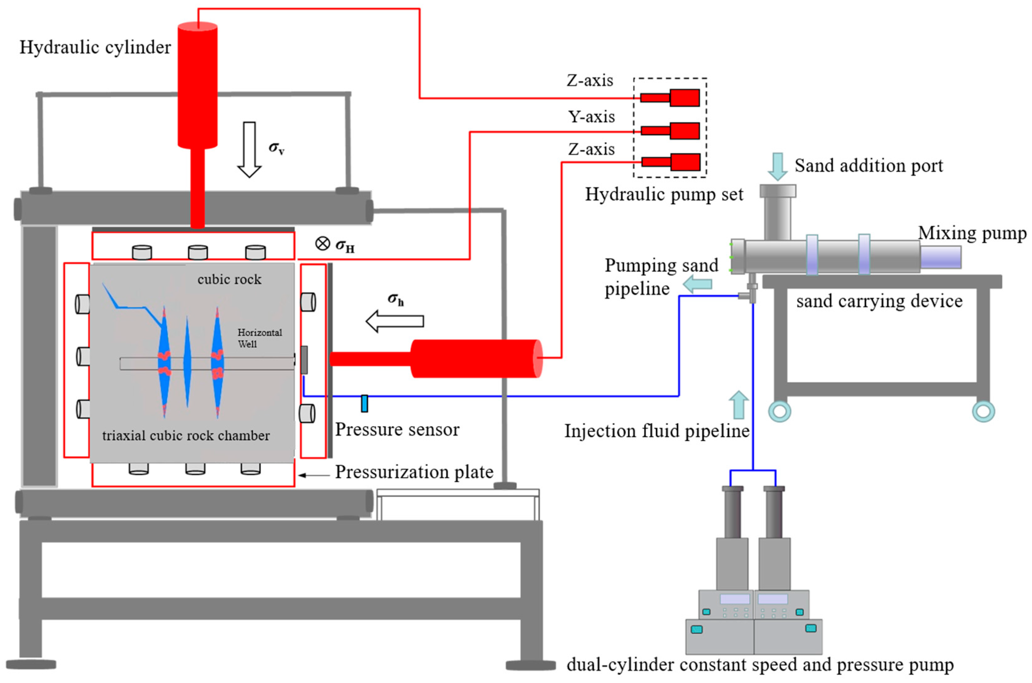
2.2.1. Experimental Apparatus

The experiment utilizes a large-scale true triaxial hydraulic fracturing simulation system (refer to Figure 1). It is capable of conducting hydraulic fracturing simulation on cubic specimens with dimensions of up to 40 cm × 40 cm × 40 cm. The maximum confining pressure that can be applied is 30 MPa. The system includes a triaxial cubic rock chamber, a hydraulic loading system, a dual-cylinder constant speed and pressure pump, a Hass alloy intermediate container, a temperature control system, a data acquisition system, and auxiliary accessories.
The fracturing sample is placed in the triaxial rock core chamber. The hydraulic loading is conducted in an adjustable frequency manner using a controller. The three axial confining pressures are sequentially hydraulically loaded in the X, Y, and Z directions until they approach the predetermined values. Then, the triaxial hydraulic servo system is initiated from the computer terminal to accurately load and stabilize the confining pressures to the predetermined values. The fracturing fluid, pre-placed in the Hass alloy intermediate container, is injected using a dual-cylinder constant speed and pressure pump. The maximum pumping rate reaches 400 mL/min. During the pumping process, the wellhead pressure is collected in real-time, and the pressure response curve is generated and fed back to the computer terminal.

2.2.2. Preparation of Fracturing Samples

The field-collected shale outcrop is cut into cubic fracturing samples with dimensions of 30 cm × 30 cm × 30 cm. A hole with a diameter of 30 mm and a length of 26 cm is drilled parallel to the BP at the center of the sample surface. A steel pipe with an inner diameter of 22 mm and an outer diameter of 27 mm is used to simulate the wellbore. The outer wall of the steel pipe is threaded to enhance the bonding strength. High-strength epoxy resin adhesive is used to consolidate the bottom of the wellbore first, and then consolidate the annulus between the outer wall of the wellbore and the borehole wall. The consolidation period for high-strength epoxy resin is 2–3 days. It is worth noting that the high-strength epoxy resin adhesive is chosen for its excellent characteristics, including high strength and fast consolidation. By using this adhesive, the wellbore integrity can be significantly enhanced, thus preventing the undesirable phenomenon of hydraulic fractures propagating directly along the wellbore wall. After consolidation, hydraulic sandblasting perforation equipment (refer to Figure 2) is used to simulate the perforation according to the predetermined scheme (refer to Table 3). Compared to the PVC pipe slotting method [17], this method can better simulate multiple-cluster perforations in horizontal wells in the field.

2.3. Experimental Parameters

Based on the actual in situ stress conditions of the Longmaxi shale reservoir [18,19,20], this study adopts the stress mechanism of strike-slip reverse faults, where the maximum horizontal stress (σH) of the cubic specimen is 25 MPa, the minimum horizontal principal stress (σh) is 10 MPa, and the vertical stress (σV) is 20 MPa. The displacement is calculated based on the similarity criteria for injection parameters using the following equation [21]:
Q M = α Q F w M × h M w F × h F
where Q is the pumping rate, w is the fracture width, h is the fracture height, α (ranging from 0.1 to 0.5) is an empirical parameter, and the subscripts M and F represent experimental and field parameters, respectively. The field operation has a displacement, fracture width, and fracture height of 10–14 m3/min, 10 mm, and 30 m, respectively. In the laboratory experiments, the fracture width and height are approximately 0.1 mm and 0.3 m, respectively. According to Equation (1), the displacement under laboratory conditions is approximately 200 mL/min. The cluster spacing is calculated based on the geometric similarity criteria using the following equation [21,22]:
S M S F = β L M L F
where S is the cluster spacing, L is the half-length of the fracture, β (=2.5) is an empirical parameter, and the subscripts M and F represent experimental and field parameters, respectively. Under field conditions, the half-length of the fracture and the cluster spacing are 100 m and 5–15 m, respectively. Under laboratory conditions, the half-length of the fracture is approximately 15 cm. According to Equation (2), the cluster spacing under laboratory conditions is approximately 2–6 cm. The detailed perforation parameters are shown in Table 3.
The fracturing process is divided into three stages: conventional fracturing stage, IFTP stage, and ISTP fracturing stage. The conventional fracturing stage uses a variable-viscosity slickwater with a viscosity of 2 mPa·s as the fracturing fluid. A green fluorescent dye is added to the fracturing fluid for tracing purposes. Initially, the pipeline is filled with approximately 500 mL under a constant pressure of 1 MPa, followed by injection at a constant rate of 200 mL/min until a pressure drop occurs and cannot be re-pressured, indicating successful fracturing. Studies have shown that a combination of different-particle-size temporary plugging agents can effectively increase the sealing pressure [23,24,25,26]. Therefore, the IFTP and ISTP stages use variable-viscosity slickwater with a viscosity of 5 mPa·s, which is supplemented with a combination of small-particle-size plugging agents (80–120 mesh + 20–80 mesh) and large-particle-size plugging agents (1–2 mm + 1–3 mm), respectively. Yellow and red fluorescent dyes are added to the fracturing fluids, respectively, and they are injected at a constant rate of 200 mL/min until the pressure stabilizes without significant fluctuations.
This study mainly analyzes the influence of cluster number and perforating method on the initiation and propagation of multi-cluster HFs during the TPDF. Five sets of experiments are designed, and the scheme is shown in Table 3.

3. Results and Discussion

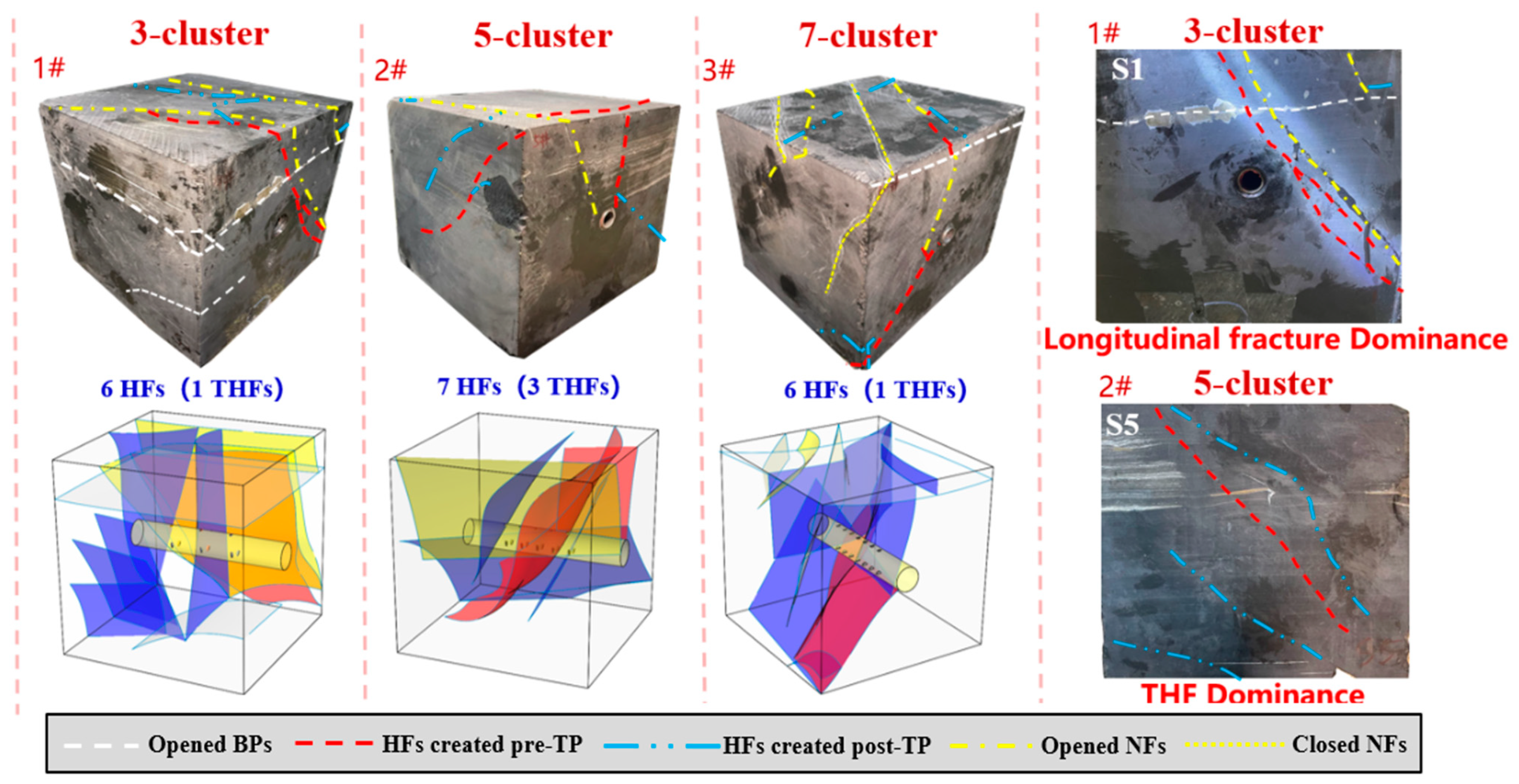
3.1. Overall Geometric Morphology of HFs

After fracturing, the distribution of HFs on the surface of the specimens was initially observed by different colored tracers. Then, cylindrical rock samples with a diameter of 12 cm and a height of 26 cm were drilled around the wellbore and subjected to three-dimensional CT scanning to observe the internal fracture morphology and the initiation of multi-cluster HFs after fracturing. It is noteworthy that the primary objective of the three-dimensional CT scanning was to observe the initiation of multi-cluster within the rock samples. Compared to conducting a comprehensive three-dimensional CT scan on the intact 30 cm × 30 cm × 30 cm shale outcrop sample after fracturing, drilling smaller-volume cylindrical rock samples and subsequently scanning them significantly improved the scanning accuracy. Based on the observed internal and external fractures, three-dimensional reconstructions were conducted. All five sets of rock samples underwent one conventional fracturing stage and two temporary plugging fracturing stages. Different perforation clusters were activated during different stages, resulting in different fracture patterns, as shown in Figure 3.

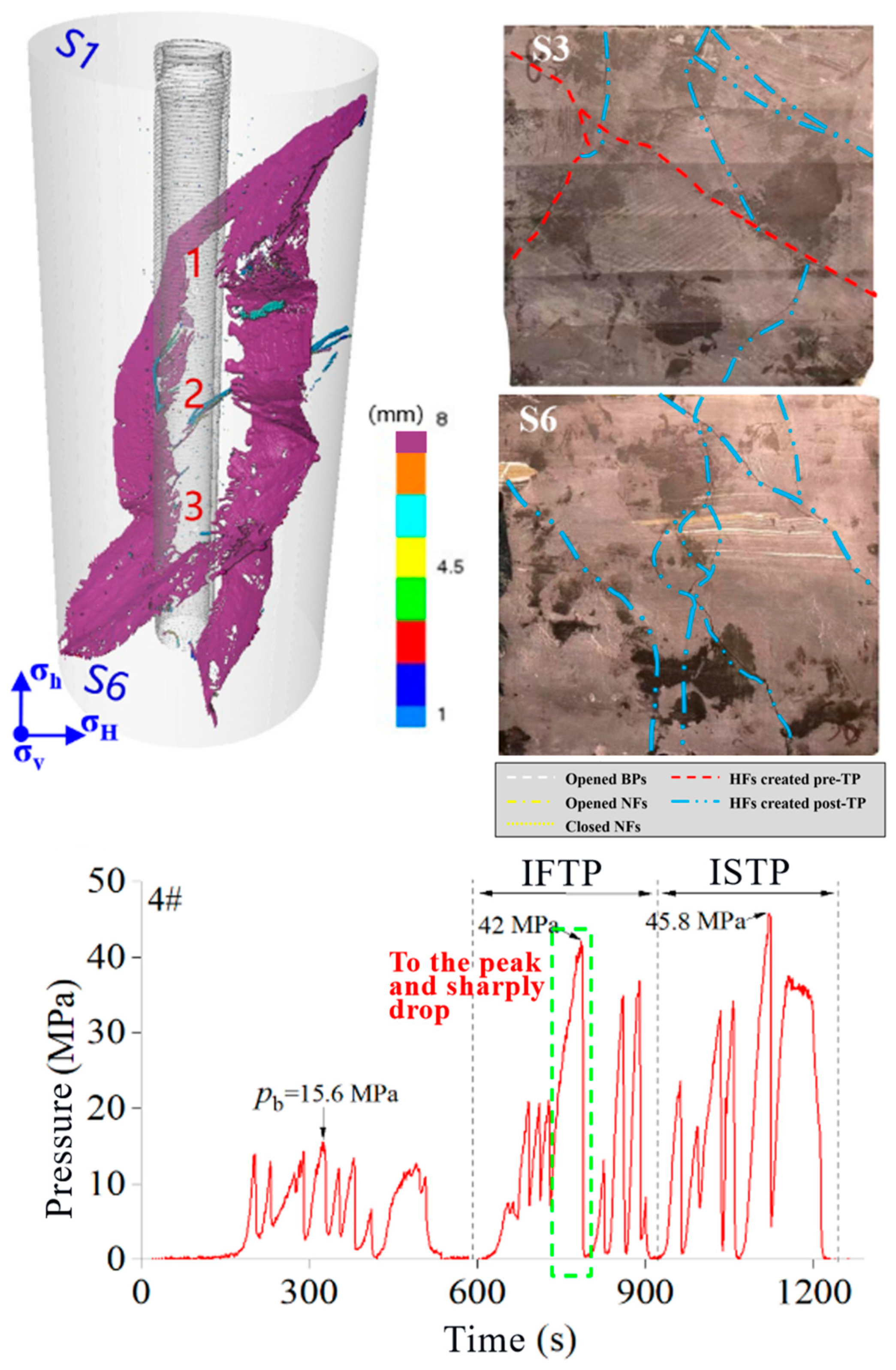
3.2. Dynamic Expansion Process of Multi-Fractures

The 1# and 4# rock samples, with three perforation clusters, were selected as representative samples to explain the dynamic expansion process of multi-cluster fractures based on the pressure curve and three-dimensional CT scanning results.
The fracture morphology and pressure curve of the 1# rock sample after fracturing are shown in Figure 4. During the conventional fracturing stage, the breakdown pressure was 12.4 MPa. The first cluster initiated a longitudinal fracture that extended to surface 1 (S1), penetrating and activating a BP located in the upper part of the wellbore. After introducing small-particle-size temporary plugging agents for IFTP, the pressure increased to a maximum of 27.9 MPa, accompanied by significant and frequent fluctuations. The original longitudinal fracture underwent a fracture tip diversion, resulting in the formation of a THF. Subsequently, large-particle-size temporary plugging agents were introduced for ISTP, and the pressure increased to 33.3 MPa. The second cluster initiated a longitudinal fracture that connected with a natural fracture, while the third cluster initiated a longitudinal fracture that extended toward S1 at a 45° angle to the wellbore, reaching S6 of the rock sample. Overall, the three longitudinal fractures were nearly parallel in initiation. However, the width of the longitudinal fracture initiated by the first cluster was significantly smaller than those of the other longitudinal fractures.
The HF morphology and pressure curve of the 4# rock sample after fracturing are shown in Figure 5. During the conventional fracturing stage, the breakdown pressure was 15.6 MPa. The first cluster initiated a THF, and it is clearly visible that this THF extended at a large angle on S3. After introducing small-particle-size temporary plugging agents for IFTP, the pressure increased to 42 MPa. The original THF underwent multiple diversions, leading to the formation of a standard longitudinal fracture that extended along the wellbore. This longitudinal fracture is clearly visible on S6, where it vertically traversed the entire rock sample. This corresponds to the peak and sharp drop in the pressure curve. Subsequently, large-particle-size temporary plugging agents were introduced for ISTP, and the pressure increased to 45.8 MPa. The second and third clusters competed to initiate fractures, each generating a THF. Neither of these two THFs penetrated the pre-existing longitudinal fracture. The THF initiated by the second cluster was influenced by the pre-existing longitudinal fracture, resulting in a narrower fracture width. The THF initiated by the third cluster mainly inclined toward S6, intersecting and communicating with the other THF, forming a complex fracture network. Overall, the three THFs were nearly parallel in initiation and underwent multiple diversions as they extended to the surface of the rock sample.
Overall, the diversion of multi-cluster fractures often corresponds to a stage of frequent pressure fluctuations at the wellhead. In this stage, the pressure reached its peak and experienced a sharp drop, indicating the formation of diversion fractures with larger fracture widths that extended to the surface of the rock sample.

3.3. Analysis of Factors Affecting HF Formation during TPDF

3.3.1. Influence of Cluster Number

To investigate the influence of cluster number on HF formation during TPDF, a comparative analysis was conducted on the 1# rock sample with 3 clusters of perforations, the 2# rock sample with 5 clusters of perforations, and the 3# rock sample with 7 clusters of perforations.
Based on the pressure response characteristics (Figure 6), under the condition of constant parameters for the temporary plugging agents, the peak pressure for IFTP in the 5-cluster rock sample was 49 MPa, and the peak pressure for ISTP was 56.4 MPa, both significantly higher than those for the 3-cluster and 7-cluster rock samples. Moreover, the peak pressures for IFTP and ISTP were similar for the 3-cluster and 7-cluster rock samples. This indicates that, based on effective temporary plugging, a 5-cluster perforation configuration is more favorable for temporary plugging and pressure buildup compared to the 3-cluster and 7-cluster configurations.
Combining the analysis of the post-fracturing rock sample fracture morphology (Figure 7), the 2# rock sample under the condition of five clusters of perforations initiated a total of 7 HFs, including 3 THFs. The overall fracture morphology of the rock sample was dominated by THFs and did not fully extend along the longitudinal fractures. In contrast, the 1# rock sample under the condition of 3 clusters of perforations and the 3# rock sample under the condition of 7 clusters of perforations initiated 6 HFs each, with only 1 THF included in each sample. The overall fracture morphology of 1# and 3# rock samples was dominated by longitudinal fractures, and the direction of extension was greatly influenced by natural fractures. This indicates that, compared to the 3-cluster and 7-cluster configurations, the 5-cluster perforation configuration resulted in a greater number of HFs and THFs, leading to more complex fracture patterns.

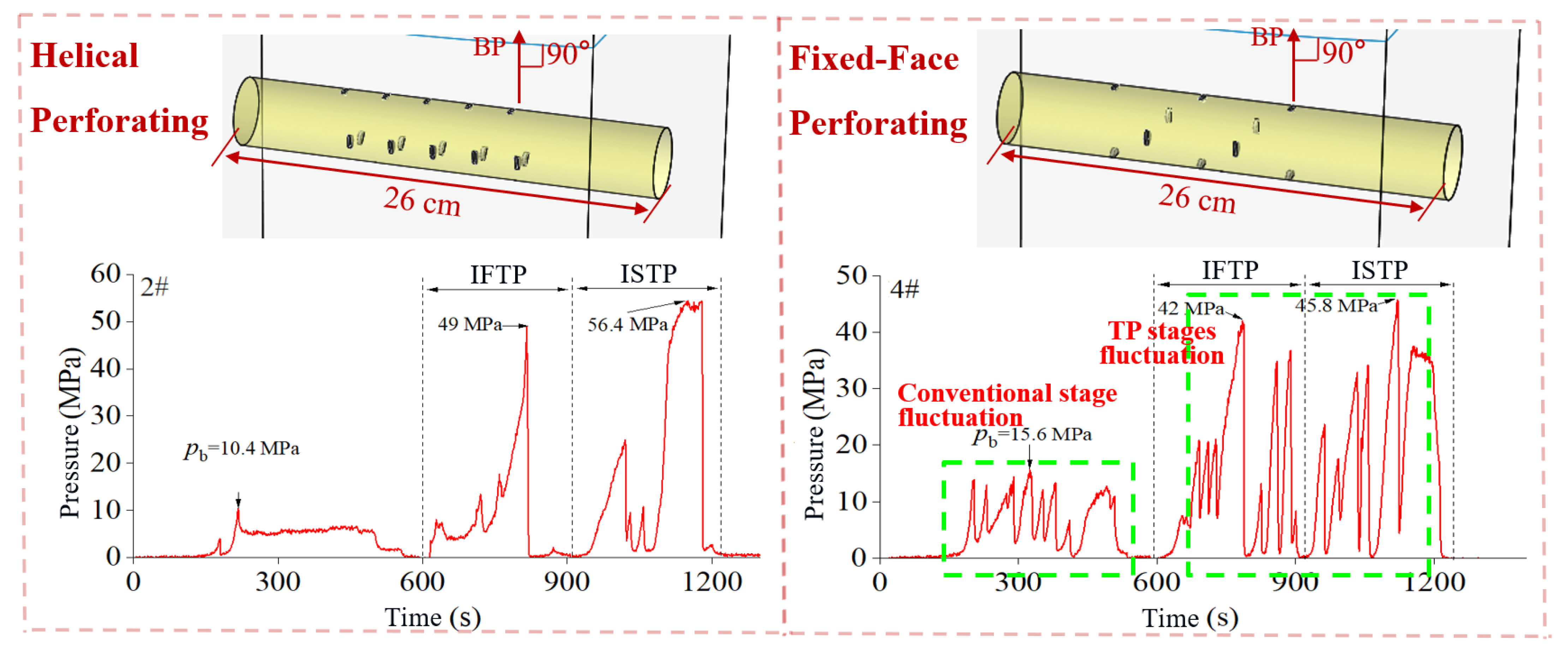
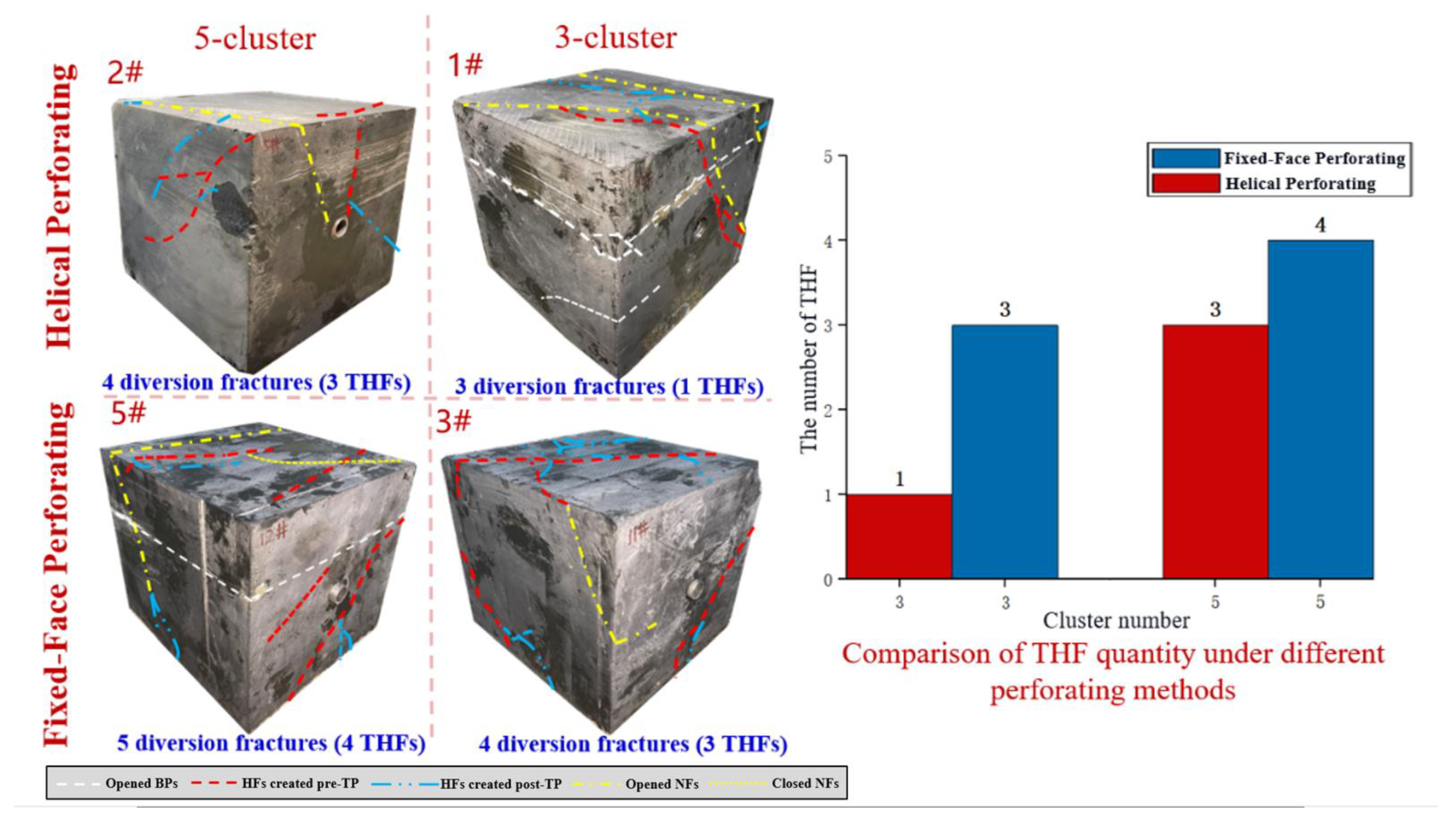
3.3.2. Influence of Perforating Method

To investigate the influence of perforating method on HF formation during TPDF, a comparative analysis was conducted on the 1# and 2# experiments using the helical perforating method and the 4# and 5# experiments using the fixed-face perforating method. The schematic representation of the two perforating methods can be seen in Figure 8.
Based on the typical pressure curves of the rock samples perforated with the helical and fixed-face methods (Figure 8), under the condition of constant parameters for the temporary plugging agents, the rock samples perforated with the fixed-face method exhibited significantly more frequent pressure fluctuations during the conventional fracturing stage and the two temporary plugging fracturing stages, indicating a more complex fracture morphology. During the conventional fracturing stage, due to the lower number of perforations (2) in the fixed-face perforating method compared to the helical perforating method (3), the rock samples perforated with the fixed-face method experienced higher breakdown pressure. However, during the IFTP and ISTP stages, there was no significant change in the peak pressure when comparing the fixed-face perforating method to the helical perforating method.
Taking into account the analysis of the post-fracturing rock sample fracture morphology (Figure 9), rock sample 5# perforated using the fixed-face method with five clusters produced a total of 5 HFs, including 4 THFs. Rock sample 2# perforated using the helical method with five clusters also produced a total of 4 HFs, with just 3 THFs. Rock sample 4# perforated using the fixed-face method with three clusters produced 4 HFs, including 3 THFs. Rock sample 4# perforated using the helical perforating method with three clusters produced just 3 THFs, with only 1 THF. This indicates that compared to the helical perforating method, the rock samples perforated using the fixed-face method exhibited more complex overall fracture morphologies, with a greater number of THFs and a higher propensity for producing diversion fractures.

4. Conclusions

The following conclusions can be drawn from this paper:
(1) The experiments have demonstrated the feasibility of conducting IFTP and ISTP fracturing in Longmaxi Formation shale reservoirs with abundant BPs. Both IFTP and ISTP can effectively build up high pressure, thereby enhancing the complexity of HFs. The generation of multi-cluster diversion fractures often corresponds to a phase of frequent pressure fluctuations at the wellhead. During this stage, the pressure reaches its peak and sharply drops, indicating the generation of diversion fractures with large widths that extend to the surface of the rock sample.
(2) Compared to 3-cluster and 7-cluster perforation, 5-cluster perforation is more conducive to temporary plugging and pressure buildup. The IFTP pressure reaches 49 MPa, while the ISTP pressure reaches 56.4 MPa. Furthermore, there are more HFs and THFs, resulting in a more complex fracture morphology. Therefore, 5-cluster perforation is considered the optimal number of clusters.
(3) Compared to the helical perforating method, the fixed-face perforating method exhibits a higher breakdown pressure during the conventional fracturing stage. Additionally, there are more frequent pressure fluctuations during the conventional fracturing stage and the two temporary plugging fracturing stages. As a result, the post-fracturing rock samples exhibit a more complex overall fracture morphology, with a greater number of THFs, which are conducive to the generation of diversion fractures.

Author Contributions

Conceptualization, Y.L.; Software, J.S.; Validation, L.Z.; Formal analysis, Y.Z.; Investigation, X.M.; Writing—original draft, C.Y.; Supervision, W.W. All authors have read and agreed to the published version of the manuscript.

Funding

This research received no external funding.

Data Availability Statement

No new data were created or analyzed in this study. Data sharing is not applicable to this article.

Conflicts of Interest

The authors declare no conflict of interest.

Abbreviations

α, βempirical parameters in the similarity equation
QM, QFpumping rate under laboratory and field conditions, m3/min
wM, wFfracture width under laboratory and field conditions, mm
hM, hFfracture height under laboratory and field conditions, m
SM, SFinter-cluster spacing under laboratory and field conditions, m
LM, LFhalf-length of the fracture under laboratory and field conditions, m
TPDFtemporary plugging and diversion fracturing
IFTPinner-fracture temporary plugging
ISTPinner-segment temporary plugging
HFhydraulic fracture
THFtransverse hydraulic fracture
BPbedding plane
XRDX-ray diffraction
CTcomputed cosmography

References

  1. Zhang, L.; Zhou, F.; Mou, J.; Pournik, M.; Tao, S.; Wang, D.; Wang, Y. Large-scale true tri-axial fracturing experimental investigation on diversion behavior of fiber using 3D printing model of rock formation. J. Pet. Sci. Eng. 2019, 181, 106171. [Google Scholar] [CrossRef]
  2. Wang, B. Investigation of Fracture Plugging and Diverting Patterns in Temporary Plugging and Diverting Fracturing; China University of Petroleum: Beijing, China, 2019. [Google Scholar]
  3. Li, M.; Zhou, F.; Sun, Z.; Dong, E.; Zhuang, X.; Yuan, L.; Wang, B. Experimental study on plugging performance and diverted fracture geometry dur-ing different temporary plugging and diverting fracturing in Jimusar shale. J. Pet. Sci. Eng. 2022, 215, 110580. [Google Scholar] [CrossRef]
  4. Li, Y.; Zhang, Q.; Zou, Y. Experimental Investigation of the Growth Law of Multi-Fracture during Temporary Plugging Fracturing within a Stage of Multi-Cluster in a Horizontal Well. Processes 2022, 10, 637. [Google Scholar] [CrossRef]
  5. Wang, M.; Wang, J.; Cheng, F.; Chen, X.; Yang, X.; Lv, W.; Wang, B. Diverter plugging pattern at the fracture mouth during temporary plugging and diverting fracturing: An experimental study. Energy Rep. 2022, 8, 3549–3558. [Google Scholar] [CrossRef]
  6. Wang, D.B.; Zhou, F.J.; Ge, H.K. Experimental study on the fiber-based diverting fracturing technology of artifi-cial fractures and its field application. Chin. J. Northeast. Pet. Univ. 2016, 40, 80–88+6. [Google Scholar]
  7. Wang, D.B. Diverting Mechanism and Its Law of Temporary Plugging in Hydraulic Fracturing; China University of Petroleum: Beijing, China, 2017. [Google Scholar]
  8. Li, W.; Ji, Z.S. Finite element analysis of temporary plugging and fracturing mechanism. Chin. J. Fault-Block Oil Gas Field 2016, 23, 514–517. [Google Scholar]
  9. Yuan, L.; Zhou, F.; Li, B.; Gao, J.; Yang, X.; Cheng, J.; Wang, J. Experimental study on the effect of fracture surface morphology on plugging effi-ciency during temporary plugging and diverting fracturing. J. Nat. Gas Sci. Eng. 2020, 81, 103459. [Google Scholar] [CrossRef]
  10. Wang, T.; Chen, M.; Wu, J.; Lu, J.; Luo, C.; Chang, Z. Making complex fractures by re-fracturing with different plugging types in large stress difference reservoirs. J. Pet. Sci. Eng. 2021, 201, 108413. [Google Scholar] [CrossRef]
  11. Hu, D.F.; Ren, L.; Li, Z.X. Simulation of fracture control during fracture-opening temporary plugging fracturing of deep/ultra deep shale-gas horizontal wells. Chin. J. Nat. Gas Ind. 2022, 42, 50–58. [Google Scholar]
  12. Zhang, R.; Hou, B.; Tan, P.; Muhadasi, Y.; Fu, W.; Dong, X.; Chen, M. Hydraulic fracture propagation behavior and diversion characteristic in shale for-mation by temporary plugging fracturing. J. Pet. Sci. Eng. 2020, 190, 107063. [Google Scholar] [CrossRef]
  13. Shi, S.; Cheng, F.; Wang, M.; Wang, J.; Lv, W.; Wang, B. Hydrofracture plugging mechanisms and evaluation methods during tempo-rary plugging and diverting fracturing. Energy Sci. Eng. 2022, 10, 790–799. [Google Scholar] [CrossRef]
  14. Bing, H.O.; Muhadasi, Y.; Weineng, F.; Peng, T. Experimental Study on the Hydraulic Fracture Propagation for Shale Temporary Plugging and Diverting Fracturing. Chin. J. Liaoning Petrochem. Univ. 2020, 40, 98–104. [Google Scholar]
  15. Wang, B.; Zhou, F.; Yang, C.; Wang, D.; Yang, K.; Liang, T. Experimental Study on Injection Pressure Response and Fracture Geometry during Temporary Plugging and Diverting Fracturing. SPE J. 2020, 25, 573–586. [Google Scholar] [CrossRef]
  16. Li, J.; Zou, Y.; Shi, S.; Zhang, S.; Wang, J.; Ma, X.; Zhang, X. Experimental Study on Fracture Propagation Mechanism of Shale Oil Reservoir of Lucaogou Formation in Jimusar. Geofluids 2022, 2022, 6598575. [Google Scholar] [CrossRef]
  17. Zhang, Z.; Zhang, S.; Zou, Y.; Ma, X.; Li, N.; Liu, L. Experimental investigation into simultaneous and sequential propagation of multiple closely spaced fractures in a horizontal well. J. Pet. Sci. Eng. 2021, 202, 108531. [Google Scholar] [CrossRef]
  18. Yushi, Z.; Shicheng, Z.; Tong, Z.; Xiang, Z.; Tiankui, G. Experimental investigation into hydraulic fracture network propagation in gas shales using CT scanning technology. Rock Mech. Rock Eng. 2016, 49, 33–45. [Google Scholar] [CrossRef]
  19. Li, N.; Zhang, S.C.; Ma, X.F.; Zou, Y.S.; Chen, M.; Li, S.H.; Zhang, Y.N. Experimental study on the propagation mechanism of hydraulic fracture in glutenite formations. Chin. J. Rock Mech. Eng. 2017, 36, 2383–2392. [Google Scholar]
  20. Li, N.; Zhang, S.C.; Zou, Y.S. Experimental analysis of hydraulic fracture growth and acoustic emission response in a layered formation. Rock Mech. Rock Eng. 2018, 51, 1047–1062. [Google Scholar] [CrossRef]
  21. Liu, G.H.; Pang, F.; Chen, Z.X. Similarity criterion in hydraulic fracturing simulation experiments. Chin. J. Univ. Pet. 2000, 5, 45–48. [Google Scholar]
  22. Naizhen, L.I.; Zhang, Z.; Yushi, Z.O.; Xinfang, M.A.; Zhang, Y. Propagation law of hydraulic fractures during multi-staged horizontal well frac-turing in a tight reservoir. Pet. Explor. Dev. 2018, 45, 1059–1068. [Google Scholar]
  23. Chen, J.; Wang, Y.; Zhao, X.; Tang, C.; Gao, Y.; Zhou, D.; Zeng, B.; Liu, X.; Li, W.; Wu, J.; et al. Chemical Agents Diversion with Microseismic Monitoring—New Prospects of Refracturing for Open-Hole Horizontal Well in Tight Oil Reservoir of Junggar Basin, China; OnePetro: Richardson, TX, USA, 2020. [Google Scholar] [CrossRef]
  24. Wu, Z.; Zou, H.; Wang, Y.; Wu, L.; Li, Y.; Xu, Y.; Wang, R.; Meng, Q.; Jiang, W.; Wang, S.; et al. Research and Application of Retreatment Technology to Tap Remaining Oil in Chang Qing Low Permeability Oilfield. In Proceedings of the International Petroleum Technology Conference, Beijing, China, 26–28 March 2020. [Google Scholar]
  25. Wang, Y.; Zhao, X.; Shang, J.; Tang, C.; Deng, J.; Xing, Y. Novel Technology to Improve Recovery of Remaining Oil in Tight Glutenite Reservoir of Junggar Basin: Employing Chemical Diverting Agents in Refracturing Operation. In Proceedings of the Abu Dhabi International Petroleum Exhibition & Conference, Abu Dhabi, United Arab Emirates, 9 November 2020. [Google Scholar]
  26. Zhang, L.F.; Zhou, F.J.; Feng, W.; Cheng, J. Temporary Plugging Mechanism of Degradable Diversion Agents within Re-produced Acid-Etched Fracture by Using 3D Printing Model. In Proceedings of the Abu Dhabi International Petroleum Exhibition & Conference, Abu Dhabi, United Arab Emirates, 9 November 2020. [Google Scholar]
Figure 1. TPDF physical simulation device.
Processes 11 02251 g001
Figure 2. Hydraulic sandblasting perforating and perforation diagram.
Processes 11 02251 g002
Figure 3. Overall fracture morphology of post-fracturing rock sample.
Processes 11 02251 g003
Figure 4. Fracture morphology and pressure curve of rock sample 1#.
Processes 11 02251 g004
Figure 5. Fracture morphology and pressure curve of rock sample 4#.
Processes 11 02251 g005
Figure 6. Relationship between the cluster number and peak pressure for IFTP and ISTP.
Processes 11 02251 g006
Figure 7. Comparison of fracture morphology under different cluster numbers.
Processes 11 02251 g007
Figure 8. Comparison of typical pressure curves between spiral perforation and fixed-face perforation.
Processes 11 02251 g008
Figure 9. Comparison of fracture morphology under different perforating methods.
Processes 11 02251 g009
Table 1. Shale mineral composition test results.
Sample IDMineral Type (%)
SiliceousCarbonateClayPyrite
1#52.09.135.94.8
2#51.26.734.17.6
3#51.411.929.37.2
4#52.710.331.93.9
average51.89.532.85.9
Table 2. Average results of shale triaxial compression test.
Core OrientationCompressive Strength
σc (MPa)
Young’s Modulus
E (GPa)
Poisson’s Ratio
Parallel BPs389.449.10.277
vertical BPs309.240.30.255
Table 3. TPDF physical simulation experimental scheme.
Rock Sample IDNumber of Cluster Perforating MethodNumber of PerforationPerforation Phase Angle (°)Spacing between Perforations (mm)Cluster Spacing (cm)Perforation Diameter
(mm)
1#3helical perforating3120554
2#52.5
3#7fixed-face perforating21802
4#35
5#52.5
Disclaimer/Publisher’s Note: The statements, opinions and data contained in all publications are solely those of the individual author(s) and contributor(s) and not of MDPI and/or the editor(s). MDPI and/or the editor(s) disclaim responsibility for any injury to people or property resulting from any ideas, methods, instructions or products referred to in the content.

