Abstract
In the pump industry, designers commonly utilize mainstream three-dimensional computer-aided design (CAD) software (Unigraphics NX 12.0 and SolidWorks 2023). However, these CAD packages are generic and not optimized for the specific requirements of the pump industry. This leads to a lack of flexibility and increased complexity in their usage, as well as higher computational demands, resulting in elevated learning and operational costs. Additionally, there are concerns about potential information leaks and software restrictions. In this paper, we studied the organization architecture of commercial three-dimensional CAD software, and compared and analyzed the geometric kernels and rendering engines of mainstream three-dimensional software. Using the Open CASCADE geometric kernel and OpenSceneGraph rendering engine, together with the Visual Studio 2021 development environment and Qt interface library, we developed an autonomous copyright three-dimensional CAD graphics support platform for pumps. Based on the three-dimensional platform, we tested the commonly used graphics elements and basic algorithms required for pump modeling, and successfully designed and modeled the impeller and volute casing of a centrifugal pump. Through computational simulations and experimental verifications, we demonstrated that the accuracy and precision of the pump model designed on this platform meets the design requirements, indicating that this platform has practical pump design and modeling capabilities. Compared to commercial three-dimensional CAD software, this platform exhibits superior flexibility and interactivity in three-dimensional modeling that is specifically tailored for pump products. Consequently, it fully satisfies the needs for three-dimensional parameterized modeling and visualization of pumps.
1. Introduction
Pumps are general-purpose machines that convert mechanical energy into the kinetic and pressure energy of the conveyed fluid. They are widely used in various fields such as agricultural irrigation, water supply and drainage, shipbuilding, and aerospace. In special sectors like petroleum and chemical industry, centrifugal pumps account for over 70% of the total pump usage [1]. Currently, in the pump industry in China, designers primarily use 2D drafting software for manual hydraulic design and 3D modeling software for three-dimensional representation. This design approach fails to fully leverage the efficiency and convenience offered by computers. It not only involves substantial engineering calculations and repetitive work, but also demands significant expenditure on software procurement and maintenance. Although there have been research efforts on pump CAD technology in recent years, resulting in the development of excellent pump design software such as PCAD (Pump hydraulic design software) [2] and PCAD-3D (3D modeling software) [3], these systems are secondary developments based on commercial CAD software. They often rely on specific versions of commercial software, necessitating constant updates of the CAD system alongside updates of the commercial 3D systems [4]. Furthermore, commercial software consumes significant memory during operation, which does not align with the requirements of lightweight and rapid design. Considering these challenges, this paper proposes developing a proprietary CAD graphics support platform with independent intellectual property rights.
In 1964, GM (General Motors) and IBM (International Business Machines) pioneered the application of CAD technology in industrial design with the development of the DAC-I system for linear design of automotive windshields. Shortly after, I.E. Sutherland developed the Sketchpad, which introduced the concept of constraints for creating standard parts in CAD systems [5,6]. In the 1970s, Gossard and Hilyard [7] presented theoretical explanations for geometric constraints and the method of variable geometry. From the 1980s onward, with rapid advancements in computer science and significant cost reductions in computer hardware, smaller CAD firms and even individuals were able to meet the hardware and software requirements for CAD development. The lower entry barrier attracted many scholars to engage in CAD research and apply their findings. For example, Aldefeld [8] proposed representing geometric elements and constraint conditions used in model creation as sets, providing an abstract representation that facilitates mathematical reasoning for computing geometric models and topological structures. Konodol [9] further simplified model creation and modification operations by applying the ideas of constraints and parametric design. Solano [10] from Spain defined constraint-based parametric design and created a standard language for defining models, along with mathematical reasoning methods for these models.
CAD technology has been widely applied in various design fields and has become an important tool in the engineering industry, including the pump industry. Commonly used CAD software for pumps includes CFturbo, BladeGen, and TURBODesign. CFturbo is a product of CFturbo GmbH in Germany [11]. This software can design various types of rotating machinery, such as pumps, fans, compressors, etc. The design process is convenient and intuitive. Designers input the design parameters of the rotating machinery, such as flow rate, head, speed, etc., and CFturbo automatically calculates other key parameters, providing great convenience to designers. CFturbo also provides many interfaces that can be connected to most CAD (Unigraphics NX and SolidWorks) and CAE (ANSYS) software on the market, facilitating model modification and simulation analysis [12]. CFX BladeGen consists of two modules: BladeGen and BladeGenPlus, which are primarily used for blade design of rotating machinery. The BladeGen module is used for blade design, while the BladeGenPlus module performs subsequent grid generation and CFD calculations. The combination of these two modules allows for predicting the performance of the blades [13]. TURBODesign is a blade design software for turbomachinery developed by the Advanced Design Technology (ADT) team. This software is suitable for various types of turbomachinery blades, including radial, mixed-flow, axial-flow, rotating and stationary, compressible and incompressible blades [14]. The distinguishing feature of this software is that it is a three-dimensional design software based on inverse design methods. Many researchers in inverse design optimization have used this software, indicating that it has comprehensive and convenient functionality in inverse design [15].
The aforementioned software provides powerful three-dimensional modeling and design capabilities that can be applied to the three-dimensional modeling of pumps. However, they are all commercial software which requires expensive annual licensing fees. Additionally, generic CAD software provides support for graphical element drawing across various industries, which limits its flexibility [16]. Since the 2000s, Liu et al. from Jiangsu University [2] developed the PCAD hydraulic design software based on the AutoCAD platform using Object ARX development tools. This software features accurate design and high efficiency, and has been widely used in the pump industry in China. Liu et al. [3] developed the PCAD-3D pump three-dimensional modeling software based on the Pro/E platform using the Pro/TOOLKIT, establishing data communication between PCAD-3D and PCAD, thus achieving three-dimensional parametric modeling of pumps. However, these software solutions still rely on commercial CAD software for normal operation, which undoubtedly increases security risks. Therefore, it is necessary to develop a lightweight pump three-dimensional CAD graphics support platform with professional characteristics and independent intellectual property rights to ensure the flexibility and security of the software.
2. Introduction of Open CASCADE
Open CASCADE, abbreviated as OCC, is an open-source geometric kernel that is an object-oriented library developed in C++. It aims to provide underlying technological support for the rapid development of specific engineering applications such as CAD, CAE, and CAM [4]. As a three-dimensional geometric kernel, OCC offers features including three-dimensional modeling visualization modules, three-dimensional solid modeling algorithms, and reading/saving three-dimensional data files [17], fully meeting the requirements for constructing a three-dimensional CAD platform for pumps. Figure 1 illustrates the architecture of Open CASCADE, presenting its functionalities and corresponding frameworks.
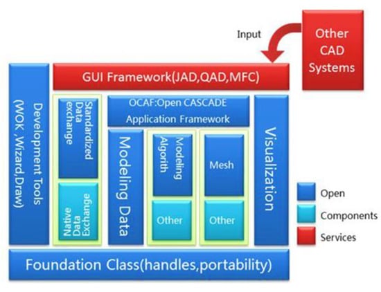
Figure 1.
Open CASCADE architecture diagram.
Open CASCADE provides various classes and functions for creating basic geometric shapes such as cones, cylinders, and tori. It also allows operations on these geometric entities, such as Boolean operations, chamfering, and spatial transformations. Some classes and functions offer geometric spatial relationship calculations and geometric analysis between 2D and 3D models. To avoid naming conflicts and duplications, Open CASCADE organizes classes into packages, prefixing the package name to the class name for differentiation. For example, the class responsible for implementing Bezier surfaces is named BezierSurface and is grouped under the package Geom. Therefore, its full name becomes Geom_BezierSurface. The library consists of packages that group together similar functionalities and is further divided into six modules: Foundation Classes, Modeling Data, Modeling Algorithms, Visualization, Data Exchange, and Application Framework. The contents of these modules and their relationships are illustrated in Table 1 and Figure 2.

Table 1.
Object Libraries modules and their contents.
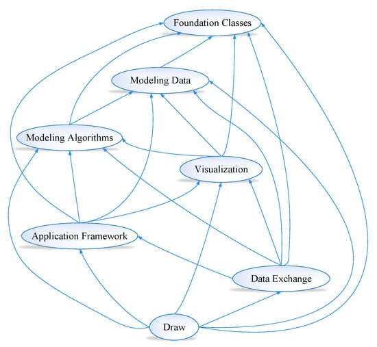
Figure 2.
Relationship between Open CASCADE modules.
The advent of Open CASCADE has provided CAD software developers with a new design approach, allowing users to conveniently and rapidly develop customized three-dimensional CAD platforms. Numerous researchers have explored and utilized the functionalities of Open CASCADE, including its modeling algorithms, file management capabilities, and visualization implementation. These efforts, combined with programming languages such as C++ and platforms like Qt, have resulted in the successful development of various three-dimensional modeling platforms based on the OpenCASCADE geometric kernel. For instance, Yuan et al. [18] leveraged Open CASCADE’s modeling algorithms, file management, and visualization implementation to develop a three-dimensional modeling platform using C++ programming language and the OCC geometric kernel. Niu et al. [19] focused on studying the OCAF file management framework of Open CASCADE, utilizing the Open CASCADE class library to create basic models, test fundamental operations, and handle CAD model files’ loading and rendering. Meanwhile, Yuan et al. [20] assessed the feasibility of combining Open CASCADE and Qt in developing complex entity modeling software within the Qt environment. In addition, Ding et al. [21] delved into the characteristics of the Open CASCADE geometric kernel library and presented a general method for constructing CAD systems using the Open CASCADE platform. They successfully built a small-scale three-dimensional CAD system that encompassed basic modeling, operations, and data conversions. Yang [22], on the other hand, extensively studied the fundamental workings and development processes of the Open CASCADE geometric kernel library, utilizing ODBC database technology to establish a model parts library. This library management system, developed through combined MFC interface libraries and Open CASCADE programming, facilitated the display of two-dimensional plane diagrams, three-dimensional model diagrams, and model attribute information. Furthermore, Zhou et al. [23]. developed MCNP-assisted modeling software based on OpenCASCADE’s geometry engine. This software not only incorporated standard functionalities expected from three-dimensional modeling software but also enabled seamless conversion between CAD models and MCNP models. Similarly, Yin et al. [4]. established a casting process CAD system for cast steel parts using Open CASCADE and wxWidgets. The system encompassed standard element modeling techniques, composite modeling approaches, parameterized design methods, and personalized positioning capabilities. With extensive research conducted by experts, scholars, and developers, three-dimensional modeling software based on the open-source geometric kernel, Open CASCADE, has emerged. Among them, FreeCAD stands out as an open-source CAD modeling software utilizing Open CASCADE, capable of running on both Windows and Linux systems, effectively addressing the fundamental needs of industrial design applications. However, it suffers from drawbacks such as an ambiguous software architecture and subpar code readability. Its suitability lies primarily in the creation of uncomplicated and streamlined three-dimensional models, while falling short in the domain of pump CAD three-dimensional modeling research and development. To address this limitation, this paper presents the development of a three-dimensional CAD graphical support platform for pumps, leveraging the Open CASCADE geometric kernel. Subsequently, the platform successfully achieved the modeling of centrifugal pump impellers, blades, and volutes, duly substantiating the viability and effectiveness of the proposed three-dimensional support platform.
3. Preparatory Work
The development process of the platform mainly includes four parts: requirement analysis, platform design, programming, and platform testing. The requirement analysis includes requirement investigation and feasibility analysis before platform development. Based on the results of the requirement analysis, the overall functions of the platform are summarized, and each function is implemented and tested through programming. This is illustrated in Figure 3.
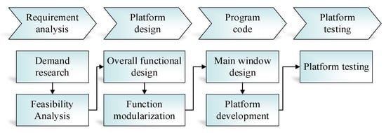
Figure 3.
Development process of platform.
By studying the organizational structure of commercial 3D CAD software, it is concluded that the 3D support platform mainly includes three main components: geometric kernel, rendering engine, and graphic user interface. The main framework is shown in Figure 4. The geometric kernel provides the necessary geometric data structure and modeling algorithms for three-dimensional modeling, including basic primitive generation (such as cubes, spheres, cylinders, etc.), basic operation algorithms (such as extrusion, fitting, Boolean operations, etc.), as well as reading and saving functions for three-dimensional data [19], which is the core layer of the 3D platform. The rendering engine primarily renders, displays, and stores loaded or generated three-dimensional geometric modeling data storage formats, serving as the foundation of the platform’s 3D visualization. The graphical user interface is mainly used to implement user-friendly human–machine interaction functions, providing a visual window for the platform, which is the top layer of the 3D platform.
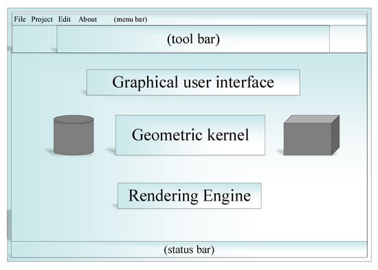
Figure 4.
Sketch map of 3D platform.
3.1. Choice of 3D Geometric Kernel
To develop a 3D CAD platform autonomously, the first step is to determine the foundational support of the CAD system, namely the geometric kernel. Currently, commonly used three-dimensional modeling software in the CAD design field corresponds to geometric kernels, as shown in Table 2 [24,25,26].

Table 2.
Geometry kernel for mainstream 3D modeling.
The 3D geometric kernels listed in Table 2 embody comprehensive and mature geometric algorithms that can achieve various complex modeling functions. Among them, Parasolid is primarily developed using C language oriented towards procedural programming, which can fully utilize computer performance and achieve faster modeling and modification speeds. ACIS, on the other hand, is developed based on object-oriented programming [27], making full use of the features of inheritance, encapsulation, and polymorphism, rendering it more secure. Currently, most mainstream 3D modeling software in the CAD field is based on these two geometric kernels, which have high stability and computing speeds. However, both ACIS and Parasolid involve relatively high commercial costs, and there are no publicly available learning materials in China, making it difficult for scholars to study and master them. Open CASCADE, just like ACIS, uses an object-oriented design method. Although it is less mature and stable, it has fully functional capabilities, open-source code, specialized maintenance and updates each year, and a better learning environment, making it more suitable for CAD program developers to study and research [21]. Considering available development resources and design principles, Open CASCADE has been selected as the geometric kernel for the 3D support platform of this project.
3.2. Choice of 3D Rendering Engine
A 3D rendering engine utilizes image processing and computer graphics techniques to convert geometric data into computer-readable image information, which is displayed in a window and provides a collection of application programming interfaces for interactive processing. A 3D graphics engine includes multiple fields such as image processing, human–computer interaction, software programming, computer graphics, etc., and should at least contain two hierarchical layers: the image rendering layer and the data interaction layer. The former provides interfaces for rendering and displaying graphic data, either designed in 3D space or loaded from external sources; the latter offers interaction function interfaces such as 3D model optimization, assembly and control. The visualization components of Open CASCADE are developed based on OpenGL. Compared to other 3D rendering engine platforms such as OpenInventor, Coin3d, OSG, and VTK, the display effect and interactive function are relatively simple. It also cannot fully utilize the GPU hardware acceleration function, resulting in slow loading and rendering speed for 3D graphic files [28]. Therefore, this platform does not adopt OpenGL as the visualization module. Currently, the outstanding 3D display engines include OpenSceneGraph, Coin3D, and OGRE. Among them, OpenSceneGraph (OSG) is a high-performance open-source 3D rendering engine library based on OSGPL license, mainly applied in modeling, gaming, VR, and scientific visualization fields [29].
Most 3D models of pumps are created using two formats: STL and STP. Therefore, this paper focuses mainly on STL as the primary format for investigation. Using the file reading interface of OSG, the speed and display effects of loading and rendering six volumes ranging from 1 MB to 12 MB in size are compared between OSG and OpenGL for STL files. The computer configuration used for this analysis is presented in Table 3. For each file, the time taken from file read to rendering completion is recorded and printed, with three sets of data collected to calculate the average time. Additionally, a line graph is generated to facilitate a visual comparison of their respective speeds.

Table 3.
Computer configuration.
As shown in Figure 5, when the size of the STL file is small, there is little difference in rendering time between the two display engines. However, as the size of the STL file increases, the efficiency of rendering with OSG is significantly higher than that of OpenGL. Therefore, from the perspective of rendering efficiency, OSG is superior to OpenGL. Moreover, as shown in Figure 6, the comparison images of OSG and OpenGL opening the same STL file (Impeller.STL) clearly reveal that OSG renders smoother, without any surface fragmentation, compared to OpenGL. Therefore, this platform uses OSG display engine to realize all the functions of 3D model rendering and display.
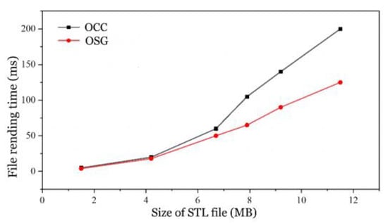
Figure 5.
Comparison of rendering file speeds.

Figure 6.
Comparison of OSG and OCC rendering effects (The left image is an OSG rendering effects, while the right image is an OCC rendering effects).
4. Development Environment Setup and Interface Implementation
4.1. Platform Development Tools
4.1.1. Development Environment
Visual Studio (VS for short) [30] is an application development integrated development environment (IDE) developed by Microsoft Corporation in Washington State, USA. Essentially, it is a toolset that includes almost all of the tools needed in the software design process. This platform uses VS (version 2021) for development.
4.1.2. Graphical User Interface
The Graphical User Interface (GUI) serves as the foundation of human–computer interaction software. The Qt GUI [31] library employed in this paper is a C++ based application framework for graphical interfaces, featuring C++ object-oriented programming characteristics and providing abundant GUI functions.
4.1.3. Programming Language
The C++ language [32] has evolved from the foundation of the C language and is widely used. It has advantages such as concise syntax, compactness, ease of use, flexibility, high-quality code generation, and fast program execution efficiency. Moreover, it supports both procedural and object-oriented programming paradigms, incorporating features such as encapsulation, inheritance, and polymorphism. Figure 7 provides a detailed description of the fundamental characteristics of object-oriented programming. The underlying source code of the Open CASCADE geometric kernel and Qt graphical user interface library, which involve computationally expensive operations such as graphics rendering and Boolean operations, are predominantly written in C++. Considering these factors, this paper selects C++ as the development language for the platform.
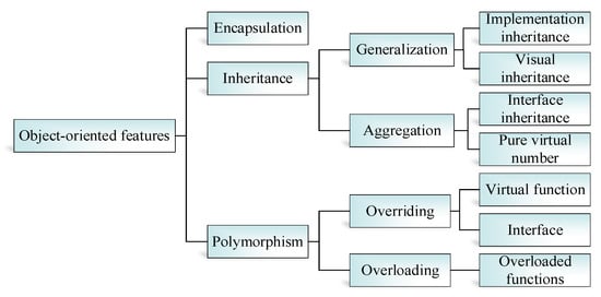
Figure 7.
Basic features of object-oriented programming.
4.2. Setting up the Development Environment for Platform
The development of the platform is based on joint programming using Visual Studio, Qt, and Open CASCADE. The overall setup of the development environment can be divided into two steps: configuring Qt and configuring Open CASCADE. Firstly, Qt needs to be configured within the Visual Studio integrated development tool. Visual Studio itself provides Qt tools. In the toolbar, under the “Extensions” and “Updates” options, search for Qt and select “Qt Visual Studio Tools” to download the Qt plugin. Once the download is complete, “Qt VS Tools” will appear in the menu bar of Visual Studio 2021. Select “Add new Qt version” to specify the path and complete the downloading of the Qt plugin. This configuration essentially enables automatic localization of the Qt compiler path by VS when compiling the Qt project.
After configuring Qt, the next step is to configure Open CASCADE. Taking version 7.4.0 of Open CASCADE as an example, the 7 modules of Open CASCADE need to be compiled in the following order: FoundationClasses.sln (basic classes), ModelingData.sln (modeling data), ModelingAlgorithms.sln (modeling algorithms), Visualization.sln (visualization), ApplicationFramework.sln (program framework), DataExchange.sln (data exchange), and Draw.sln (drawing). Once the compilation is complete, add the include files and lib files from the opencascade-7.4.0 folder to the include directories and library directories. Manually add library files such as shell32.lib, TKernel.lib, TKMath.lib, etc., in the Additional Dependencies section of the property pages to complete the configuration of Open CASCADE in Visual Studio 2021, ensuring that the basic functionality of Open CASCADE can be realized.
4.3. Data Transmission and Window Implementation
The main window of the platform refers to the display window where the program is run, which includes the Menu bar, Tool bars, Dock widgets, Status bar, and Central widget. The Menu bar is used to display text menus for files, projects, settings, and so on. The Tool bars are used to place frequently used graphic tool buttons. The Dock widgets, also known as floating windows, are mainly used to display current design parameters. The Status bar is used to display prompt messages and running state information. The Central widget is the main display and interaction window that forms the basis of the platform’s main interface. Sub-windows refer to the windows that appear after clicking a button in the main window. They are responsible for human–machine interaction and allow designers to input and modify design parameters during the design process. Data transfer between the windows of the platform includes three types of situations: passing values from the main window to sub-windows, passing values from sub-windows to the main window, and passing values between sub-windows. This can be seen in Figure 8.

Figure 8.
Data Transfer Method Between Windows.
Using the Qt Interface Library, the program was designed based on different modules, as shown in Figure 9, and resulted in the main window shown in Figure 10.

Figure 9.
The implementation steps for the main window.
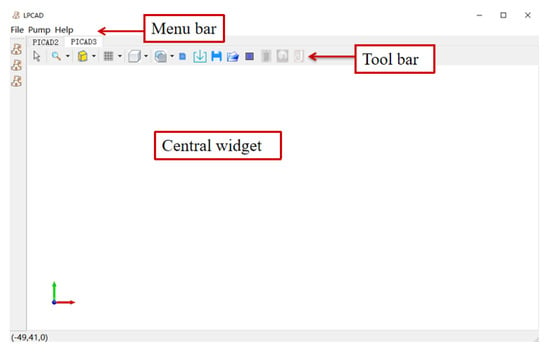
Figure 10.
The main interface of 3D support platform.
4.4. Three-Dimensional Visualization
After completing the window interface design of the 3D platform, users are able to conveniently develop their own 3D visualization functions that meet their requirements by utilizing the encapsulation libraries included in OpenSceneGraph [33]. As an open-source display engine, OpenSceneGraph has a wide range of encapsulation libraries, mainly divided into the following five categories.
The five modules mentioned in Table 4 can constitute a 3D rendering window with basic interactive functions, and its basic organizational structure is shown in Figure 11.

Table 4.
The Encapsulation Libraries of OpenSceneGraph.
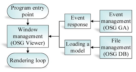
Figure 11.
Basic structure of OpenScenceGraph rendering module.
The 3D visualization architecture in OpenSceneGraph mainly consists of four classes: Graphic3d_GraphicDriver, osgGraphicsContext, osgViewer, and osgView. These classes provide a comprehensive framework for creating and rendering complex 3D scenes and models, including support for advanced graphics techniques such as lighting, texture mapping, and shading. The Graphic3d_GraphicDriver class serves as the primary interface for interacting with the graphics hardware, while the osgGraphicsContext class provides a context for graphics resources. The osgViewer class manages the overall rendering pipeline, including the management of viewports, cameras, and scene graphs, while the osgView class provides a platform-specific implementation of a view for rendering the 3D scene. Together, these classes form a powerful and flexible 3D visualization system that can be easily extended and customized to meet a wide range of needs and requirements.
To implement 3D visualization based on OpenSceneGraph, the following steps (as shown in Figure 12) need to be taken, and the 3D window obtained after running the program is shown in Figure 13. This realizes the 3D visualization function of the platform.
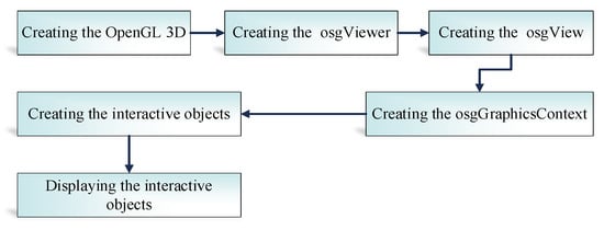
Figure 12.
Steps for 3D Visualization.
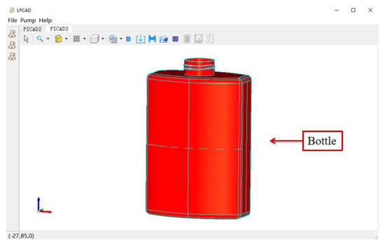
Figure 13.
3D window based on OpenScenceGraph.
4.5. Basic Geometric Modeling
By exploring the geometric kernel algorithms of Open CASCADE and using the MakeBox, MakeCone, MakeSphere, MakeCylinder, and MakeTorus classes provided by the Open CASCADE library, common geometric primitives such as cubes, cones, spheres, cylinders, and circular cylinders were modeled on the established 3D support platform, as illustrated in Figure 14. Additionally, the basic operational algorithms related to 3D modeling of pump designs were investigated and tested, including Fillet, Boolean, and Prism functions, as depicted in Figure 15.
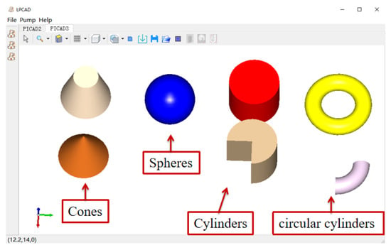
Figure 14.
Diagram of basic element.
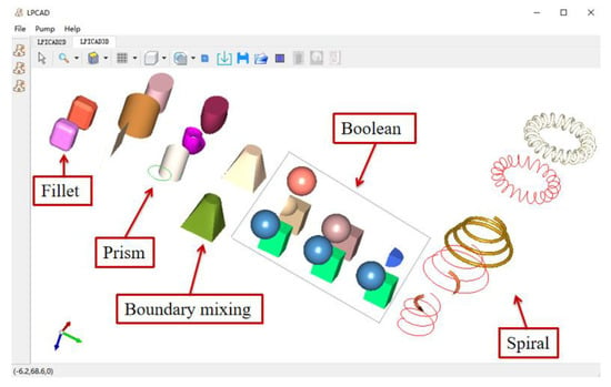
Figure 15.
Fundamental algorithms implementation.
5. Three-Dimensional Modeling of Centrifugal Pump Impellers and Volutes Based on the Platform
5.1. Three-Dimensional Modeling of Impellers
Three-dimensional modeling of centrifugal pump impellers represents a critical aspect of pump design [34], as the hydraulic design of impellers has important implications for the efficiency, head, and cavitation of centrifugal pumps [35]. In the process of impeller design, the primary geometric parameters of the impeller are first calculated based on design parameters. Then, a blade meridian is drawn based on the primary geometric parameters. Once the shape of the blade meridian has been determined, the entire impeller flow path is divided into multiple small channels, with multiple streamline points obtained from these individual channels. The grid expansion method is then used to obtain the blade camber line from these streamline points, followed by the thickening of the blade and retrieval of the blade back line. The blade camber line is then transformed into the blade axis section line, after which the working surface and back surface of the blade are drawn based on the axis section line, and subsequently fitted to generate the blade. The design process is illustrated in Figure 16.
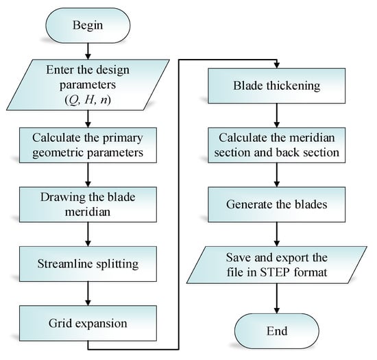
Figure 16.
Blade design process.
Through the blade design flowchart, program design is performed on this platform. Click the quick button for impeller design, enter the design parameter input interface, and start designing the centrifugal pump impeller. Parameter input interface is shown in Figure 17. In this interface, the pump type can be selected, and the design parameters of the pump can be inputted: Flow rate (Q), Head (H), Speed (n), Impeller stages (i). The platform will automatically calculate the specific speed (ns) of the pump based on the design parameters (as shown in Table 5). The final 3D model of the blade is shown in Figure 18.
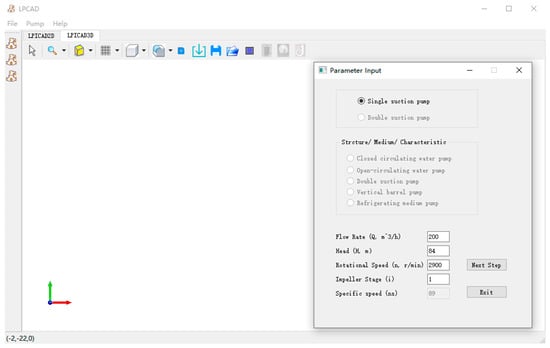
Figure 17.
Interface for design parameters of input impeller.

Table 5.
Design parameters of impellers.
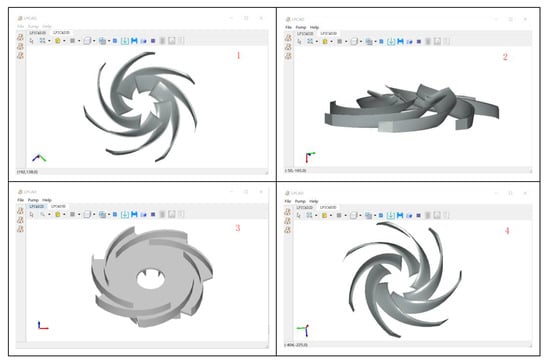
Figure 18.
3D modeling of different blades.
5.2. Three-Dimensional Modeling of Volute
The volute, also known as the spiral casing, is a flow-through component in a centrifugal pump that converts liquid energy [36]. From a hydraulic perspective, it has the advantages of a wide high-efficiency region and broad applicability [37].
In volute design, the main geometric parameters of the volute are first calculated, and the front seven section areas are determined based on the eighth section area. While ensuring the areas of the eight sections, the section shape is designed, and the spiral section is generated. After determining the outlet section parameters, the transitional section shapes from the eighth section to the outlet section are obtained. Typically, two transitional sections are used, namely, the ninth and tenth sections. The outlet position is chosen as a central outlet or a side outlet, and the diffuser section with different shapes is generated based on the transitional sections. The shape of the tongue is determined by parameters such as the tongue placement angle and tongue radius. Finally, the volute is assembled by combining the spiral section, diffuser section, and tongue. The design procedure is shown in Figure 19.
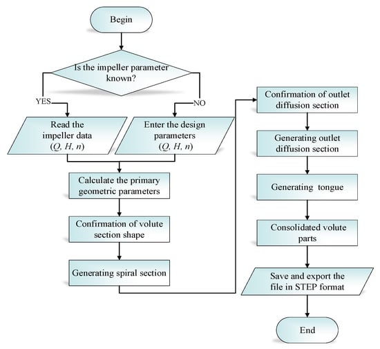
Figure 19.
Flow chart for volute design.
Click on the volute design button to enter the volute design parameter input interface and start designing the centrifugal pump volute. Figure 20 shows the volute parameter input interface, where the designer can select the volute design details and input the pump design parameters. If the impeller of the centrifugal pump has been designed previously, the program will automatically read the impeller’s design parameters, as well as the impeller outer diameter and outlet diameter data. If there is no relevant data for the impeller design, the program will provide recommended values for the impeller outer diameter and outlet diameter based on the design parameters inputted by the designer. The final volute model obtained is shown in Figure 21 and design parameters are shown in Table 6.
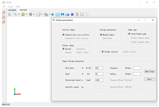
Figure 20.
Input interface for volute housing parameters.
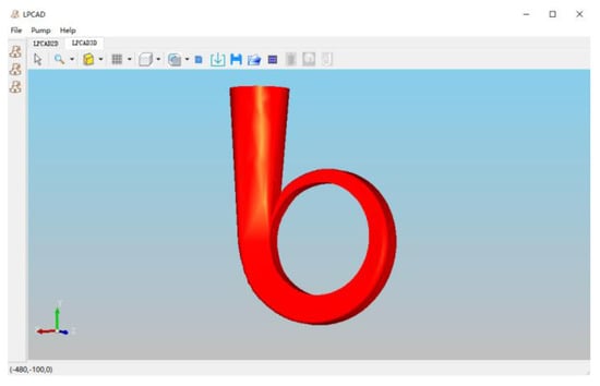
Figure 21.
Volute model.

Table 6.
Design parameters of volute.
6. Computational and Experimental Validation
To verify the reliability of the pump 3D platform, this paper conducts numerical calculations and experimental validation on a designed centrifugal pump with a specific speed of 90. The design parameters of this pump are shown in Table 7.

Table 7.
Design parameters of centrifugal pumps.
Based on the design parameters, the impeller and volute were designed on the 3D platform. After completion, the inlet and outlet extension sections were drawn based on the input and output data, and the pump assembly was carried out. The assembled pump is shown in Figure 22. The computational domain was partitioned into tetrahedral meshes using ANSYS ICEM CFD, with additional grid refinement added to the volute tongue, impeller rounding, and interface regions to ensure quality. The overall mesh quality was maintained at or above 0.30.
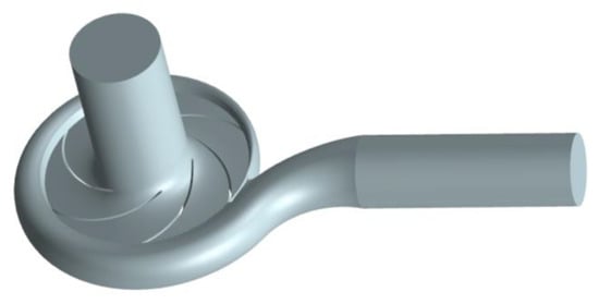
Figure 22.
Assembly drawing of 3D model.
The design target head of the centrifugal pump was 33m. After calculation, the head of the centrifugal pump at the design working condition was 33.47m, which differed from the design target by 1.42%. The designed scheme met the requirements for subsequent numerical simulations. Furthermore, the feasibility of the numerical simulation was verified via energy performance testing experiments on the model pump. The comparison curve between the experimental and simulated results is shown in Figure 23. As can be seen from the figure, at the design working condition, the difference between the design head and the experimental value was 1.56%, and the difference in efficiency was 1.36%. Therefore, at the design working condition, the difference between the simulated and experimental values of the centrifugal pump was small, which suggests that using the 3D platform to design the centrifugal pump is feasible. The accuracy and precision of the design and modeling can meet the requirements of subsequent CFD calculations.
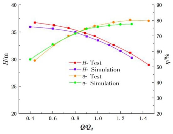
Figure 23.
External characteristic curves of centrifugal pump.
7. Conclusions
This paper presents the successful development of a three-dimensional CAD graphics support platform for pumps. The platform was developed using the Visual Studio 2021 development environment and incorporates the Open CASCADE geometry kernel, the OpenSceneGraph rendering engine, and the Qt graphical user interface library. It provides essential functionality for viewing, displaying, and modeling three-dimensional pumps. With complete independent intellectual property rights, this platform offers enhanced flexibility and interactivity in three-dimensional pump product modeling, surpassing that of commercial CAD design software. An innovative aspect of the platform is the utilization of the OpenSceneGraph rendering engine instead of the OpenGL visualization component of Open CASCADE. This implementation choice improves data loading efficiency and enhances rendering effects. Building upon this robust three-dimensional platform, the paper investigates design and modeling algorithms for centrifugal pump impellers and volutes. Through calculations and experiments, the accuracy and precision of pump models designed on this platform are validated, meeting the design requirements. The three-dimensional CAD graphical support platform for pump design provides design and modeling functionalities. Nevertheless, the predictive analysis of pump performance remains dependent on the individual design engineer’s experience. To enhance design efficiency, future development of the platform can involve integration with a backend database, thereby incorporating performance prediction capabilities. Following the completion of the design process, designers can retrieve analogous pump data from the database and employ appropriate algorithms to deliver performance prediction results, effectively augmenting design efficiency.
Author Contributions
Conceptualization, H.L.; Data curation, S.Y.; Funding acquisition, L.D.; Methodology, H.L. and Z.W.; Project administration, L.D.; Resources, Y.W.; Software, S.Y.; Writing—original draft, Z.W.; Writing—review and editing, Y.W. All authors have read and agreed to the published version of the manuscript.
Funding
This research was funded by the National Natural Science Foundation of China (No. 52279087, 51879122), Program Development of Jiangsu Higher Education Institutions (PAPD), and Jiangsu top six talent summit project (GDZB-017).
Data Availability Statement
Restrictions apply to the availability of the data. Data are proprietary to the National Pump and System Engineering Technology Research Center, and are available from the authors with the permission of the National Pump and System Engineering Technology Research Center.
Conflicts of Interest
The authors declare that they have no known competing financial interest or personal relationships that could have appeared to influence the work reported in this paper.
References
- Orrù, P.F.; Zoccheddu, A.; Sassu, L.; Mattia, C.; Cozza, R.; Arena, S. Machine Learning Approach Using MLP and SVM Algorithms for the Fault Prediction of a Centrifugal Pump in the Oil and Gas Industry. Sustainability 2020, 12, 4776. [Google Scholar] [CrossRef]
- Liu, H. Development of Pump Hydraulic Design Software PCAD 2004. Pump Technol. 2005, 1, 15–17+47. [Google Scholar]
- Liu, M. Parametric 3D Modeling of Pump and Its Software Development; Jiangsu University: Zhenjiang, China, 2006. [Google Scholar]
- Yin, Y.; Wang, T.; Wang, Z.; Huang, Z.; Shen, X.; Zhou, J. Research and Development of Casting Process CAD System for Steel Casting based on OpenCASCADE and wxWidgets. Procedia Manuf. 2019, 37, 348–352. [Google Scholar] [CrossRef]
- Hartono, S. Effectiveness of geometer’s sketchpad learning in two-dimensional shapes. Math. Teach.-Res. J. Online 2020, 12, 23–25. [Google Scholar]
- Eu, L.K. Impact of geometers sketchpad on students achievement in graph functions. Malays. Online J. Educ. Technol. 2014, 1, 17–20. [Google Scholar]
- Luo, H.; Zhang, X.-P.; Xiang, W.; Zhou, J. Development status and Prospect of Constrained Parametric Design Technology. China Mech. Eng. 1995, 6, 21–25. [Google Scholar]
- Aldefeld, B. Variation of geometric based on a gemotric-reasoning method. Comput.-Aided Des. 1998, 20, 117–126. [Google Scholar] [CrossRef]
- Koichi, K. PIGMOD: Parametric and interactive geomtric modeler for mechanical design. Comput.-Aided Des. 1990, 22, 623–644. [Google Scholar]
- Liuis, S.; Brunet, P. Constructive constraint-based model for parametric CAD systems. Comput.-Aided Des. 1994, 26, 614–621. [Google Scholar]
- Zhang, S.; Wang, C.; Sun, T.; Zhang, D. Research on design method of twisted impeller of centrifugal Pump based on CFturbo. Fluid Mach. 2016, 44, 56–59. [Google Scholar]
- Xu, Y.; Song, W.; Fu, J.; Jin, Y. Analysis of influence of volute with different area ratio on performance of centrifugal pump. China Rural. Water Resour. Hydropower 2015, 8, 172–175. [Google Scholar]
- Ding, L.; Feng, J.; Liu, X.; Zhang, S.L. Application of CFX-BladeGen in turbine blade modeling. Chin. J. Eng. Des. 2005, 2, 109–112. [Google Scholar]
- Zhang, R.; Yang, J.; Li, R. Inverse design method of centrifugal pump blade based on Partial Differential Equation. Trans. Chin. Soc. Agric. Mach. 2009, 9, 81–84. [Google Scholar]
- Lu, Y. Research and Application of Binding Design Method for Core Components of Hydraulic Model of CAP1400 Nuclear Main Pump; Dalian University of Technology: Dalian, China, 2019. [Google Scholar]
- Zhao, H.; Wang, H.; Zhang, X. Axis 3D Parametric Design System Based on OpenCASCADE. Mach. Build. Autom. 2019, 4, 97–99. [Google Scholar]
- Zhuo, Y.; Zhan, H.X.; Wu, X.; Chen, J.F.; Pan, J.H. Integration of 3D Mechanical and 2D Electronic Design Based on Open CASCADE. Appl. Mech. Mater. 2014, 635–637, 616–620. [Google Scholar] [CrossRef]
- Yuan, G.; Zhang, Y. Development and Research of 3D Modeling Platform using Open CASCADE. J. Eng. Graph. 2008, 4, 146–149. [Google Scholar]
- Niu, B.; Wei, Z. Development of 3D Modeling Software Based on Open CASCADE. Mech. Eng. 2013, 3, 52–54. [Google Scholar]
- Yuan, Y.; Wang, Y.; Jiang, L.; Lin, C.; Wang, Y. Research on modeling Technology based on QT and OPENCASCADE. Mod. Electron. Technol. 2013, 10, 74–77. [Google Scholar]
- Ding, H.; Wang, Z. Research on CAD System Development Based on OPEN CASCADE Platform. J. Southwest Univ. Sci. Technol. 2014, 2, 72–76. [Google Scholar]
- Yang, L.; Han, S.-J.; Chen, W.; He, J.-S. Development and research of 3D Model Software based on Open CASCADE. Mech. Eng. 2015, 12, 43–45. [Google Scholar]
- Zhou, Q.; Sun, H.; He, S.; Yang, J.; Tian, Y. Development of an MCNP assisted modelling software based on OpenCasCade. Int. J. Ad Hoc Ubiquitous Comput. 2017, 25, 75–84. [Google Scholar] [CrossRef]
- Yang, H. Implementation of 3D Modeling Software Based on Geometric Engine Library Open CASCADE; Lanzhou University: Lanzhou, China, 2015. [Google Scholar]
- Zobrist, G.W. Information & computer science—Parametric and feature-based CAD/CAM concepts, techniques, and applications by Jami J. Shah and Marttti Mantyla. Choice Rev. Online 1996, 33, 1830. [Google Scholar]
- Spatial Corp. Michael Payne to Provide Keynote at Spatial’s 3D Insiders’ Summit 2010. Comput. Wkly. News. 2010, 9, 597. [Google Scholar]
- Feng, Y. Design and Implementation of 3D CAD Geometric Engine Data Structure; Shandong University: Jinan, China, 2022. [Google Scholar]
- Xu, W. Design and Implementation of Aero Engine Blade Reconstruction Module Based on Open CASCADE; Southeast University: Nanjing, China, 2017. [Google Scholar]
- Ni, Z.; Ji, W. Porting and running of OSG Engine in Android Studio. Comput. Appl. Softw. 2018, 35, 212–214,236. [Google Scholar]
- Weiss, T.R. Microsoft Releases Visual Studio 2019, Visual Studio 2019 for Mac.; eWeek: Foster City, CA, USA, 2019. [Google Scholar]
- Fine, V.E. Cross-platform Qt-based implementation of low level GUI layer of ROOT. Nucl. Instrum. Methods Phys. Research. Sect. A: Accel. Spectrometers Detect. Assoc. Equip. 2003, 502, 681–683. [Google Scholar] [CrossRef]
- Hock, P.; Nakayama, K.; Arai, K. A Tool for C++ Header Generation: An Extension of the C++ Programming Language. Int. J. Adv. Comput. Sci. Appl. 2019, 10, 458–465. [Google Scholar]
- Lee, C.; Kim, J.; Kim, K.-I. Implementation of Altitude Information for Flight Simulator in OpenSceneGraph. IEMEK J. Embed. Syst. Appl. 2014, 9, 11–16. [Google Scholar] [CrossRef]
- Chen, W.; Li, Y.; Liu, Z.; Hong, Y. Understanding of energy conversion and losses in a centrifugal pump impeller. Energy 2023, 263, 125787. [Google Scholar] [CrossRef]
- Dai, C.; Wang, Z.; Dong, L.; Qiu, J.; Chen, Y. Effect of obstacle placement on cavitation performance of centrifugal pump. J. Drain. Irrig. Mach. Eng. 2022, 40, 122–127. [Google Scholar]
- Li, C.; Wang, Y.; Li, X.; Chen, H.; Wei, Y.; Wu, G. A two-dimensional method for radial turbine volute design. Proc. Inst. Mech. Eng. Part A J. Power Energy 2023, 237, 33–47. [Google Scholar] [CrossRef]
- Sun, H.; Xu, H.; Li, Y.; Wang, X.; Li, Y. Parametric Analysis and Optimization Design of the Twin-Volute for a New Type of Dishwasher Pump. Processes 2023, 11, 305. [Google Scholar] [CrossRef]
Disclaimer/Publisher’s Note: The statements, opinions and data contained in all publications are solely those of the individual author(s) and contributor(s) and not of MDPI and/or the editor(s). MDPI and/or the editor(s) disclaim responsibility for any injury to people or property resulting from any ideas, methods, instructions or products referred to in the content. |
© 2023 by the authors. Licensee MDPI, Basel, Switzerland. This article is an open access article distributed under the terms and conditions of the Creative Commons Attribution (CC BY) license (https://creativecommons.org/licenses/by/4.0/).