Dynamic Analysis of a Bolted Joint Rotor-Bearing System with a Blade–Casing Rubbing Fault


Abstract
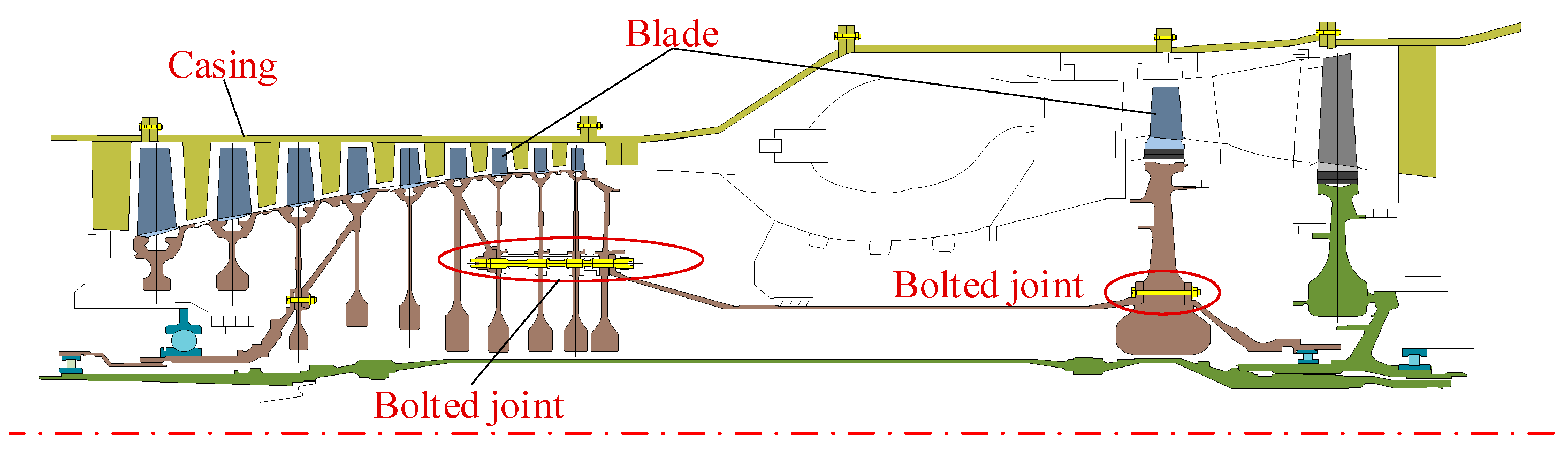
:1. Introduction
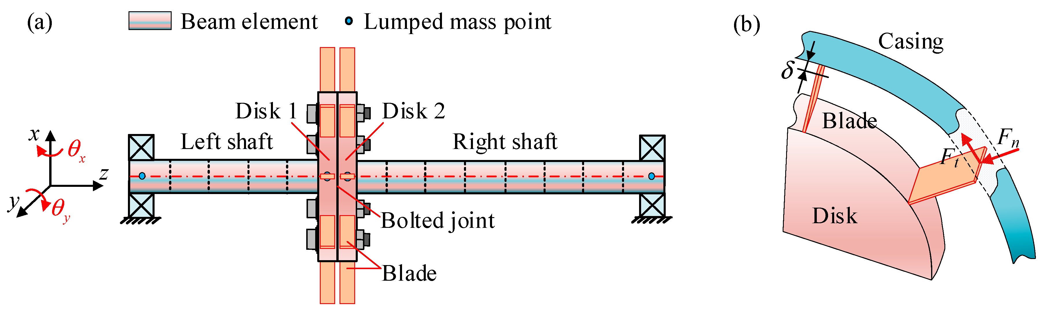
2. Motion Equations for a Rotor System with Blade–Casing Rubbing Fault
2.1. Blade–Casing Rubbing Force Model
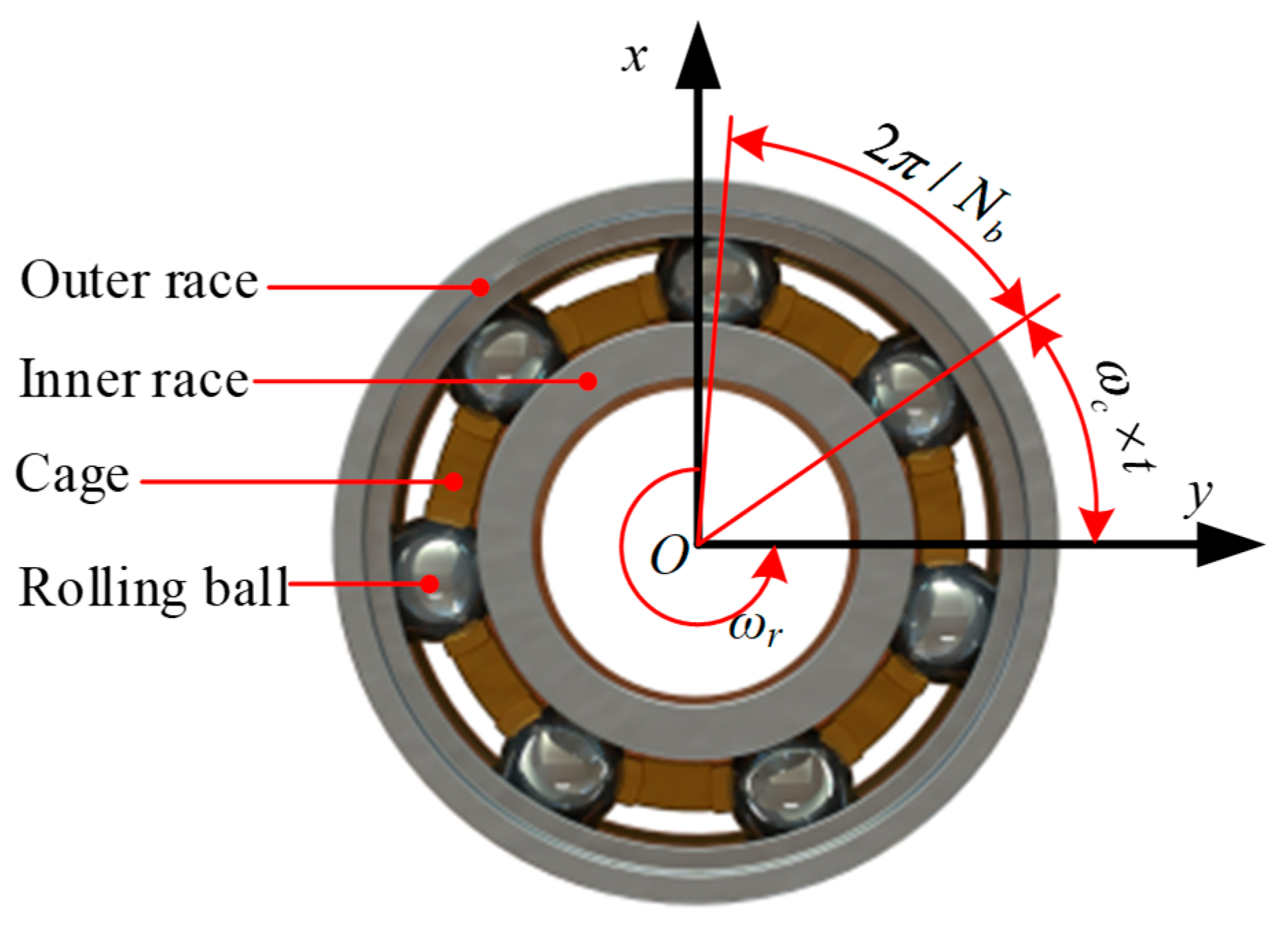
2.2. Rolling Bearing Force Model
- (a)
- The inner race is connected to the rotating shaft, and the outer race is connected to the bearing house so that no relative slippage occurs during operation of the rotor system.
- (b)
- The rolling ball exhibits pure rolling, without a sliding motion, and the displacement between the balls is equal during operation.
2.3. Dynamic Model of Bolted Joint
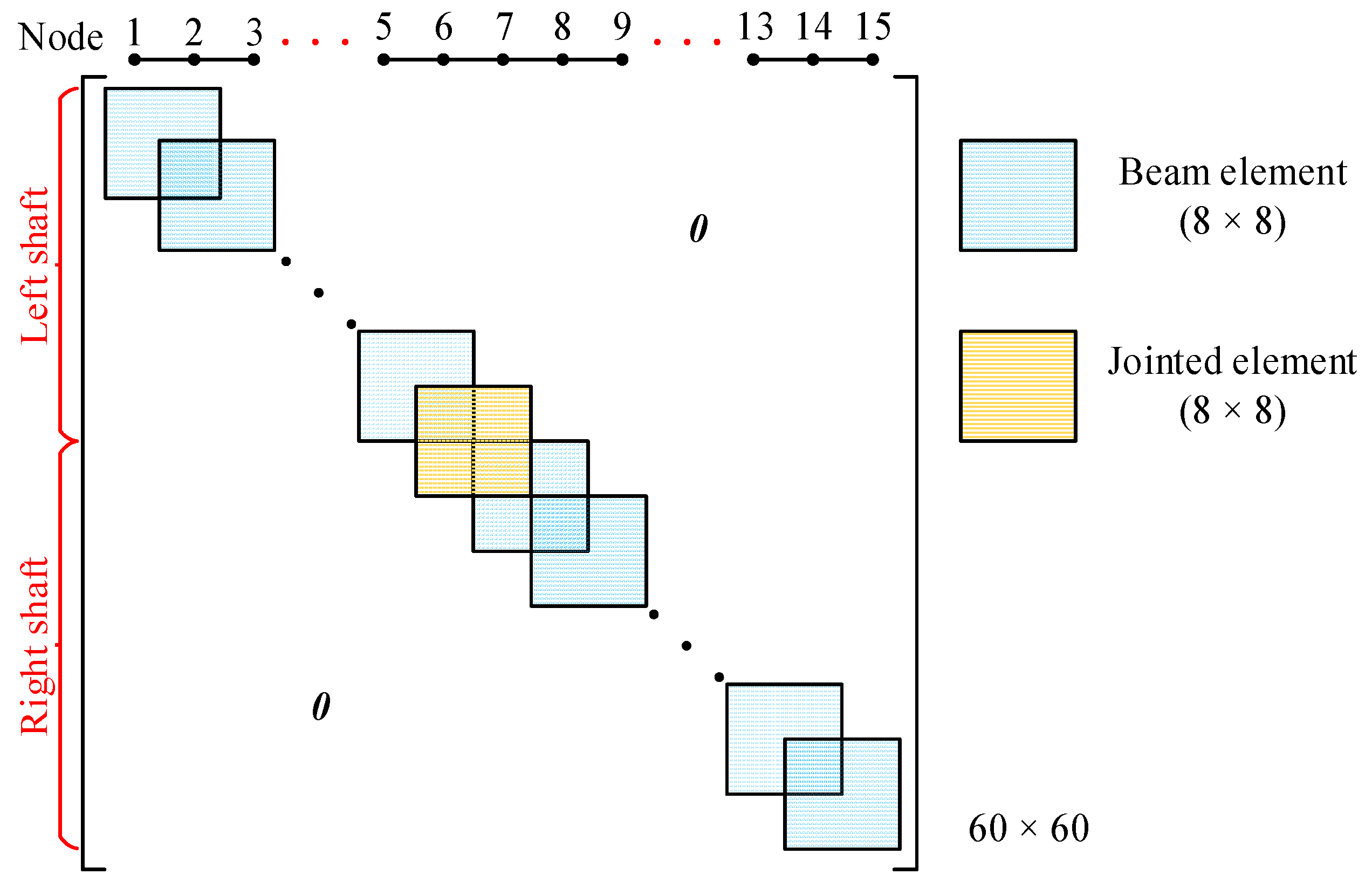
2.4. Global Motion Equations of Bolted Joint Rotor–Bearing System
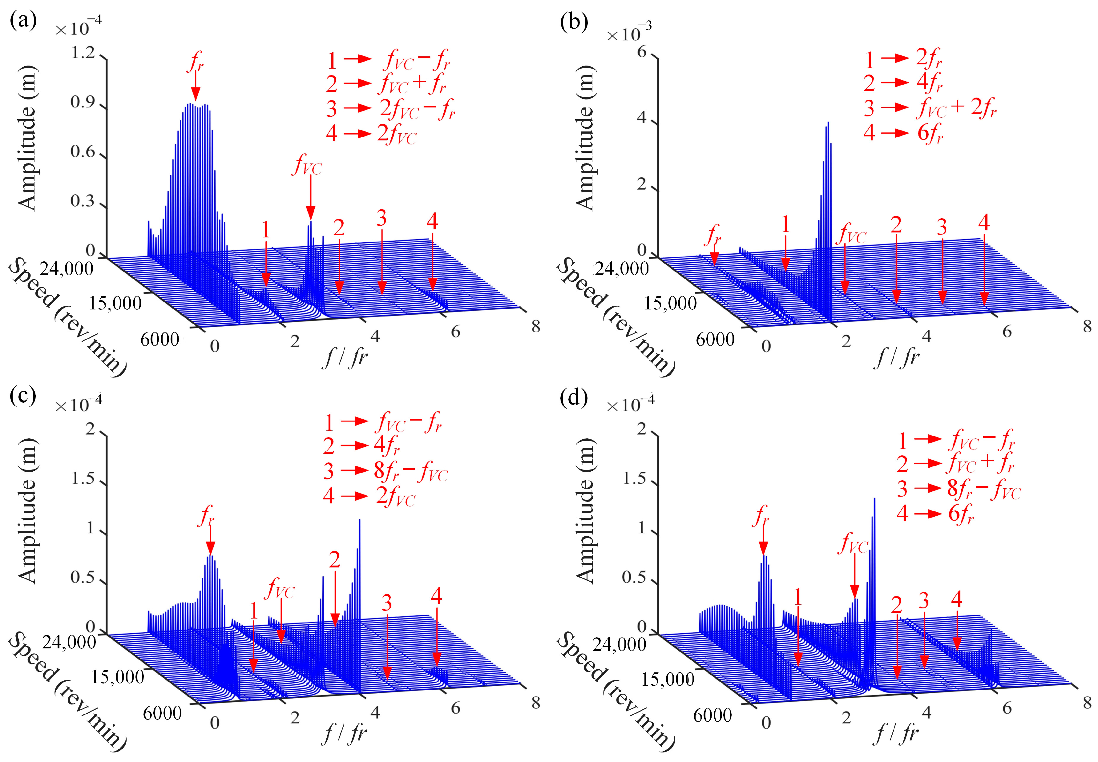
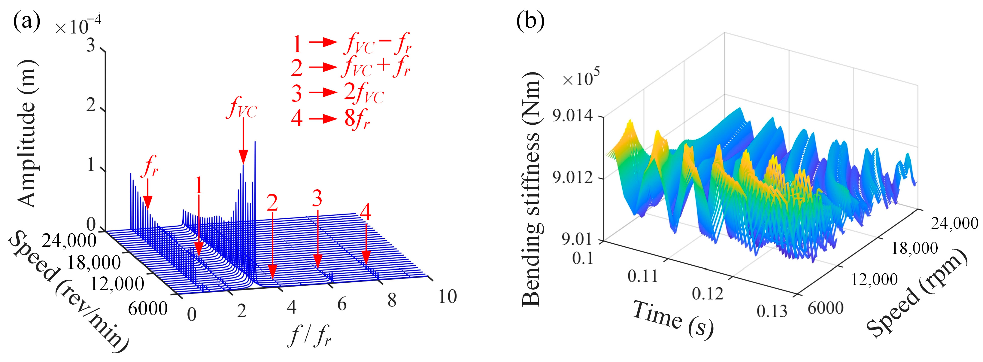
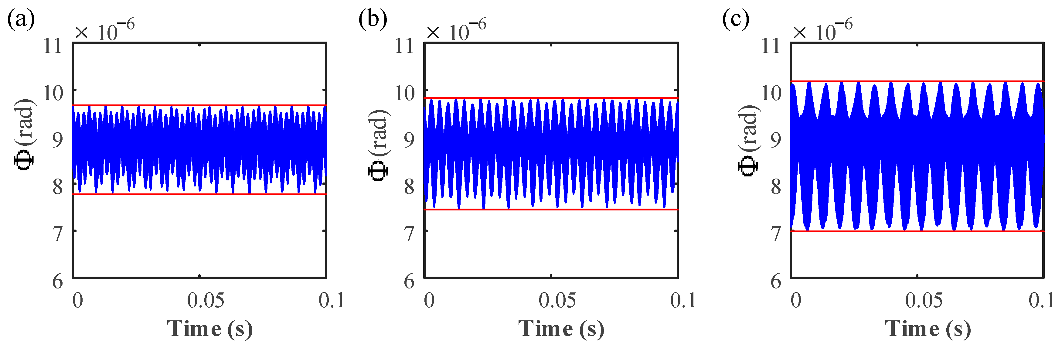
3. Verification Based on Response Spectra
4. Numerical Simulation Results and Discussions
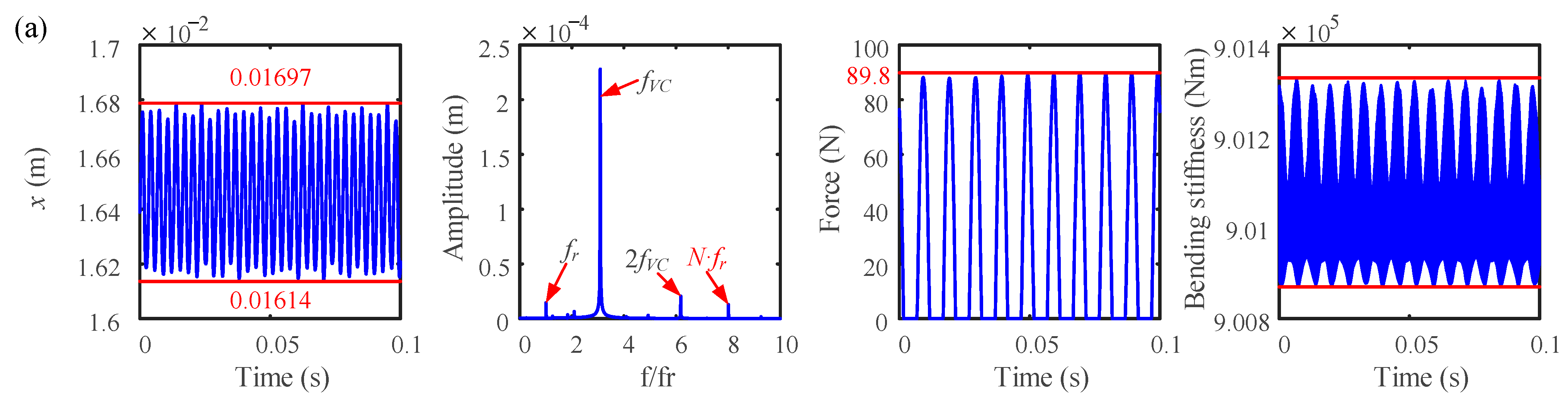
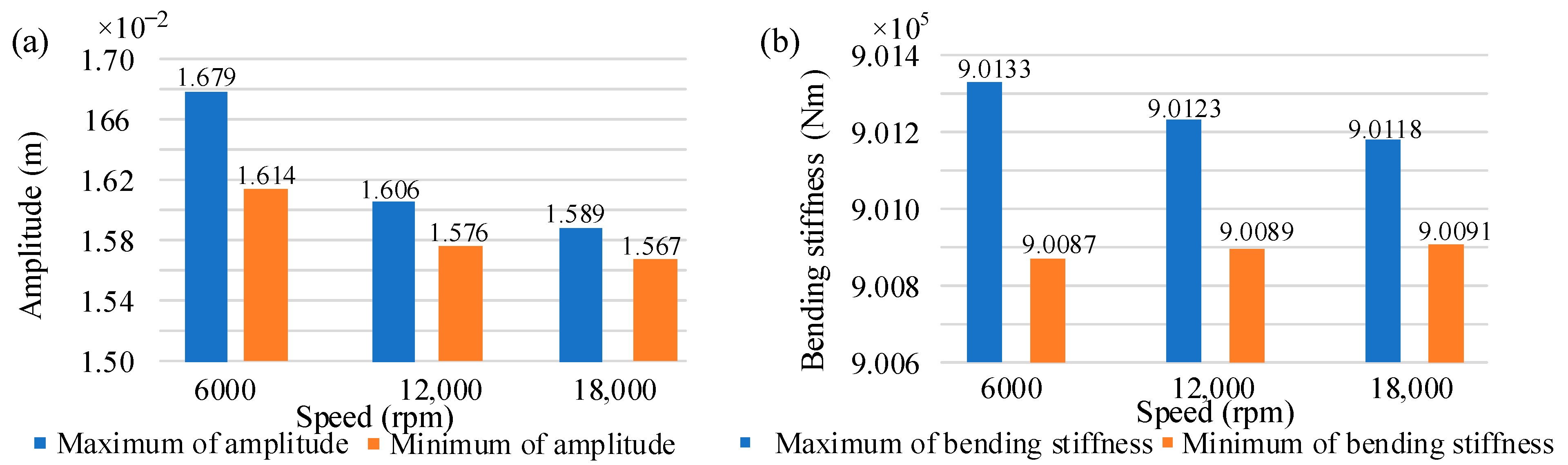
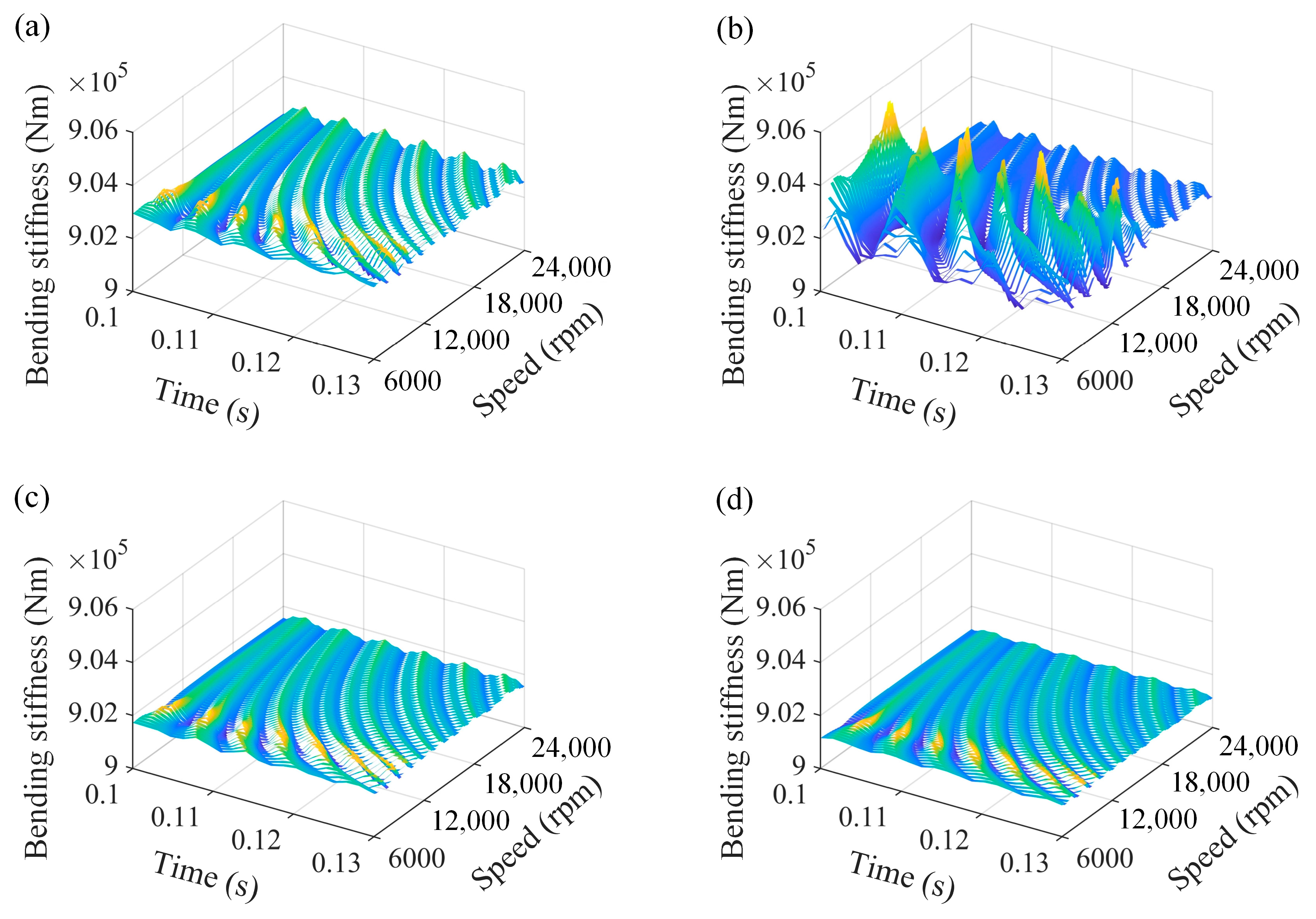
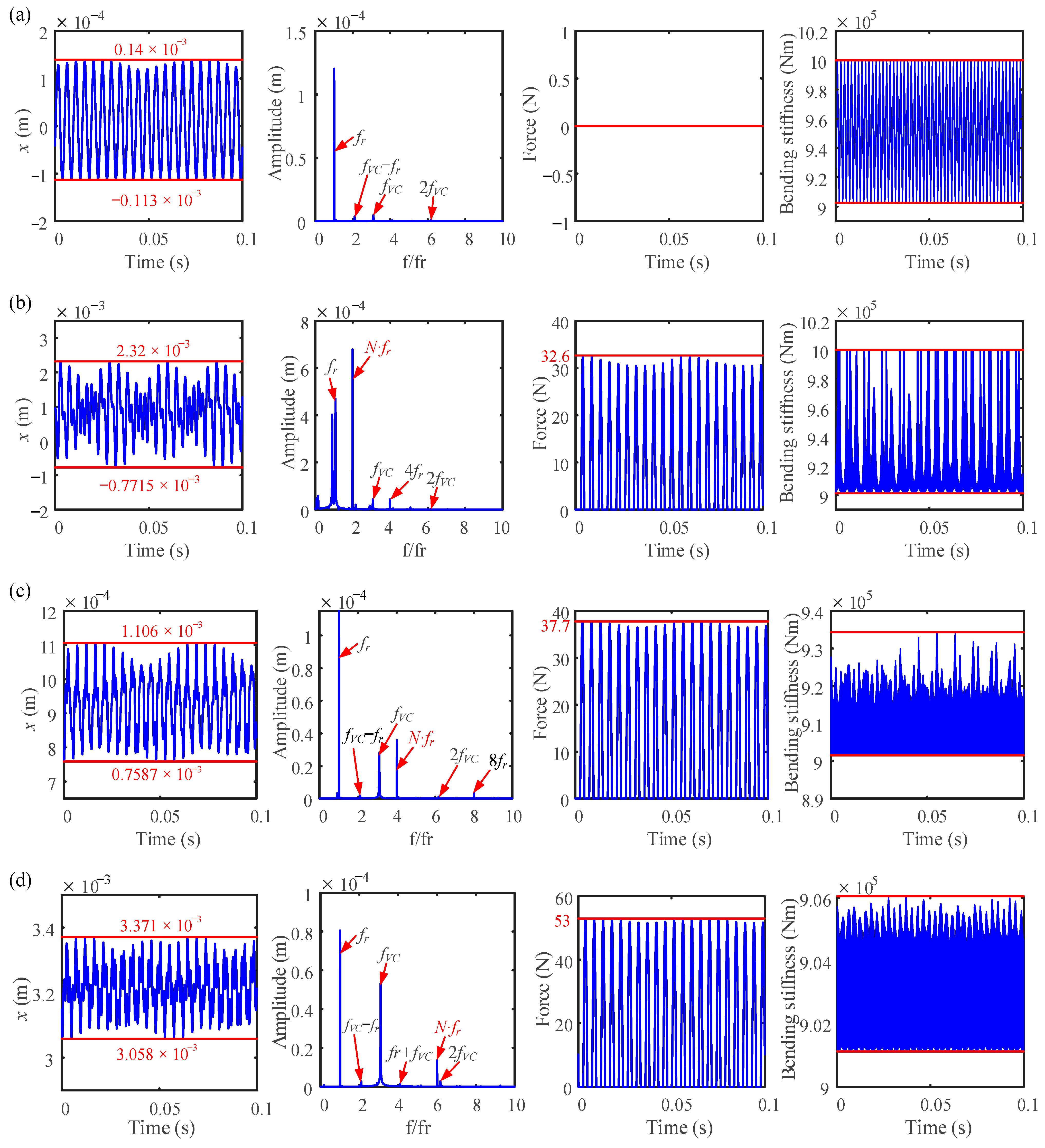
4.1. Effects of Rotational Speed
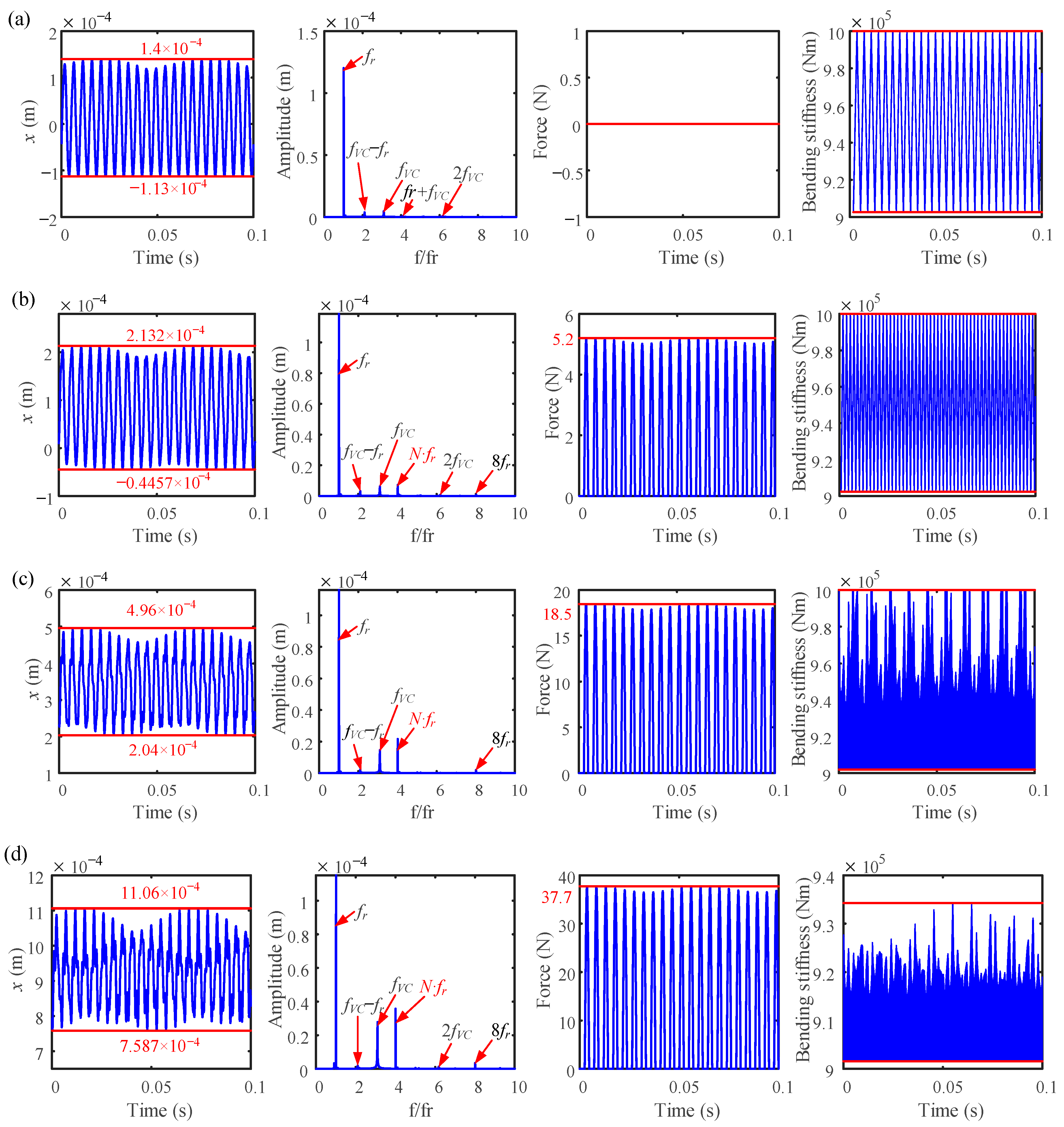
4.2. Effects of Number of Blades
4.3. Effects of Casing Stiffness
5. Conclusions
- When a rubbing fault occurs, the time-domain waveform becomes complicated, and the response amplitude changes slightly as the number of blades increases. As the number of blades increases, the mean value of the vibration response deviates significantly from 0.
- The frequency component fVC’s amplitude increases as the number of blades rises, and this increase in frequency also obviously raises the maximum value of the normal rubbing force. Furthermore, as the number of blades rises, the bending stiffness falls and eventually becomes even lower than it was under working conditions.
- As the number of blades rises, the amplitude of the normal rubbing force decreases as the rotation angle between the adjacent disks increases; meanwhile, the bending stiffness of the bolted joint enters the second stage as a result of the vibration gradually being aggravated by the rubbing fault.
- The rubbing effect becomes greater at a larger casing stiffness, and the amplitude of the passing frequency of the blade will increase significantly as the contact stiffness increases.
Author Contributions
Funding
Data Availability Statement
Conflicts of Interest
Nomenclature
| Fni, Fti | Normal and tangential force generated by the blade–casing rubbing (N) |
| N | Number of uniformly distributed blades |
| xd, yd | Vibration displacements of the disk (m) |
| rd | Radius of the disk (m) |
| lb | Length of the blade (m) |
| kr | Casing stiffness (N/m3/2) |
| ri | Radial displacement at the ith blade tip (m) |
| Fx, Fy | Rubbing force acting on the rotor (N) |
| ro, ri | Outer and inner radius of the bearing (mm) |
| Kc | Hertz contact stiffness (N/m3/2) |
| Fbx, Fby | Bearing forces in the x- and y-directions |
| , , , | Mass, damping, gyroscopic, and stiffness matrices of the jointed element |
| Displacement vector of the bolted joint | |
| Force matrix of the bolted joint | |
| kθ | Bending stiffness between the adjacent disks of the bolted-joint structure |
| kθ1, kθ2 | Bending stiffnesses at the first and second bending stages |
| , , , | Mass, damping, gyroscopic, and stiffness matrices of the left shafts |
| , , , | Mass, damping, gyroscopic, and stiffness matrices of the right shafts |
| , | Displacement vector of the left shafts and right shafts |
| , | Force matrix of the left shafts and right shafts |
| M, C, G, K | Mass, damping, gyroscopic, and stiffness matrices of the rotor system |
| q | Displacement vector of the rotor system |
| F, Fg | Force matrix and gravity vector of the rotor system |
| f1, f2 | The first and second natural frequencies |
| fbi | Normal contact force between the ith rolling ball and the raceway |
| a, b | Rayleigh damping coefficients |
| Nb | Number of ball elements |
| N | Number of uniformly distributed blades |
| Greek letters | |
| ωr | Rotating speed |
| θbi | Angle between the ith blade and the y-axis |
| δi | Clearance between the ith blade and casing |
| ωc | Rotational speed of the cage |
| ωVC | Frequency of varying compliance vibration |
| γ0 | Radial clearance of the bearing |
| δbi | Contact deformation of the bearing |
| γ0 | Radial clearance of the bearing |
| Rotation angle between the adjacent disks | |
| Relative rotation angle at the transition point | |
| ξ1, ξ2 | Modal damping ratios |
Appendix A
Appendix B
References
- Ma, H.; Yin, F.; Guo, Y.; Tai, X.; Wen, B. A review on dynamic characteristics of blade-casing rubbing. Nonlinear Dynam. 2016, 84, 437–472. [Google Scholar] [CrossRef]
- Qin, Z.Y.; Han, Q.K.; Chu, F.L. Analytical model of bolted disk-drum joints and its application to dynamic analysis of jointed rotor. Proc. Inst. Mech. Eng. Part C J. Mech. Eng. Sci. 2014, 228, 646–663. [Google Scholar] [CrossRef]
- Kou, H.; Shi, Y.; Du, J.; Zhu, Z.; Zhang, F.; Liang, F.; Zeng, L. Rub-impact dynamic analysis of a rotor with multiple wide-chord blades under the gyroscopic effect and geometric nonlinearity. Mech. Syst. Signal Process. 2022, 168, 108563. [Google Scholar] [CrossRef]
- Jin, Y.; Liu, Z.; Yang, Y.; Li, F.; Chen, Y. Nonlinear vibrations of a dual-rotor-bearing-coupling misalignment system with blade-casing rubbing. J. Sound Vib. 2021, 497, 115948. [Google Scholar] [CrossRef]
- Yang, Y.; Chen, G.; Ouyang, H.; Yang, Y.; Cao, D. Nonlinear vibration mitigation of a rotor-casing system subjected to imbalance-looseness-rub coupled fault. Int. J. Nonlin. Mech. 2020, 122, 103467. [Google Scholar] [CrossRef]
- Yang, Y.; Ouyang, H.; Yang, Y.; Cao, D.; Wang, K. Vibration analysis of a dual-rotor-bearing-double casing system with pedestal looseness and multi-stage turbine blade-casing rub. Mech. Syst. Signal Process. 2020, 143, 106845. [Google Scholar] [CrossRef]
- Ma, H.; Yin, F.; Wu, Z.; Tai, X.; Wen, B. Nonlinear vibration response analysis of a rotor-blade system with blade-tip rubbing. Nonlinear Dynam. 2016, 84, 1225–1258. [Google Scholar] [CrossRef]
- Ma, H.; Lu, Y.; Wu, Z.; Tai, X.; Wen, B. Vibration response analysis of a rotational shaft-disk-blade system with blade-tip rubbing. Int. J. Mech. Sci. 2016, 107, 110–125. [Google Scholar] [CrossRef]
- Zeng, Z.; Zhang, D.; Tong, R.; Xu, H. Experimental investigation and analytical modeling for blade-casing rubbing force. Mech. Syst. Signal Process. 2022, 167, 108548. [Google Scholar] [CrossRef]
- Colaïtis, Y.; Batailly, A. The harmonic balance method with arc-length continuation in blade-tip/casing contact problems. J. Sound Vib. 2021, 502, 116070. [Google Scholar] [CrossRef]
- Piollet, E.; Nyssen, F.; Batailly, A. Blade/casing rubbing interactions in aircraft engines: Numerical benchmark and design guidelines based on nasa rotor 37. J. Sound Vib. 2019, 460, 114878. [Google Scholar] [CrossRef] [Green Version]
- Thiery, F.; Gustavsson, R.; Aidanpää, J.O. Dynamics of a misaligned kaplan turbine with blade-to-stator contacts. Int. J. Mech. Sci. 2015, 99, 251–261. [Google Scholar] [CrossRef]
- Thiery, F.; Aidanpää, J. Nonlinear vibrations of a misaligned bladed jeffcott rotor. Nonlinear Dynam. 2016, 86, 1807–1821. [Google Scholar] [CrossRef] [Green Version]
- Torkhani, M.; May, L.; Voinis, P. Light, medium and heavy partial rubs during speed transients of rotating machines: Numerical simulation and experimental observation. Mech. Syst. Signal Process. 2012, 29, 45–66. [Google Scholar] [CrossRef]
- Wang, N.; Liu, C.; Jiang, D. Experimental analysis of dual-rotor-support-casing system with blade-casing rubbing. Eng. Fail. Anal. 2021, 123, 105306. [Google Scholar] [CrossRef]
- Qin, Z.Y.; Han, Q.K.; Chu, F.L. Bolt loosening at rotating joint interface and its influence on rotor dynamics. Eng. Fail. Anal. 2016, 59, 456–466. [Google Scholar] [CrossRef]
- Zhao, S.; Zhang, L.; Zhu, R.; Han, Q.; Qin, Z.; Chu, F. Modeling approach for flexible shaft-disk-drum rotor systems with elastic connections and supports. Appl. Math. Model. 2022, 106, 402–425. [Google Scholar] [CrossRef]
- Zhang, Y.; Xiang, L.; Su, H.; Hu, A.; Yang, X. Dynamic analysis of composite rod fastening rotor system considering multiple parameter influence. Appl. Math. Model. 2022, 105, 615–630. [Google Scholar] [CrossRef]
- Li, T.; Yang, D.; Zhao, B.; Sun, Q.; Huo, J.; Sun, W. Measured and investigated nonlinear dynamics parameters on bolted flange joints of combined rotor. J. Mech. Sci. Technol. 2021, 35, 1841–1850. [Google Scholar] [CrossRef]
- Zhou, W.; Zhang, R.; Ai, S.; He, R.; Pei, Y.; Fang, D. Load distribution in threads of porous metal–ceramic functionally graded composite joints subjected to thermomechanical loading. Compos. Struct. 2015, 134, 680–688. [Google Scholar] [CrossRef] [Green Version]
- Mir-Haidari, S.; Behdinan, K. Nonlinear effects of bolted flange connections in aeroengine casing assemblies. Mech. Syst. Signal Process. 2022, 166, 108433. [Google Scholar] [CrossRef]
- Zhou, W.; Ai, S.; Chen, M.; Zhang, R.; He, R.; Pei, Y.; Fang, D. Preparation and thermodynamic analysis of the porous zro2/(zro2 + ni) functionally graded bolted joint. Compos. Part B Eng. 2015, 82, 13–22. [Google Scholar] [CrossRef]
- Du, B.; Qin, Z.; Lu, Q.; Wang, B.; Li, C. Dynamic modeling of tie-bolt rotors via fractal contact theory and virtual material method. Proc. Inst. Mech. Eng. Part C J. Mech. Eng. Sci. 2022, 236, 2141141063. [Google Scholar] [CrossRef]
- Zhang, Y.; Liu, S.; Xiang, L.; Hu, A. Dynamic analysis of a multi-disk rod fastening rotor system with rub-impact based on multiple parameters. Nonlinear Dynam. 2022, 107, 2133–2152. [Google Scholar] [CrossRef]
- Zhang, Y.; Xiang, L.; Hu, A.; Chen, K. Nonlinear dynamic response on multi-fault rod fastening rotor with variable parameters. Appl. Math. Model. 2023, 114, 147–161. [Google Scholar] [CrossRef]
- Zhao, R.; Jiao, Y.; Chen, Z.; Li, Z.; Qu, X. Nonlinear analysis of a dual-disk rotor system considering elastoplastic contact. Int. J. Nonlin. Mech. 2022, 141, 103925. [Google Scholar] [CrossRef]
- Yu, P.; Li, L.; Chen, G.; Yang, M. Dynamic modelling and vibration characteristics analysis for the bolted joint with spigot in the rotor system. Appl. Math. Model. 2021, 94, 306–331. [Google Scholar] [CrossRef]
- Li, P.; Yuan, Q. Stress variation of a gas turbine tie-bolt rotor with hirth serrations considering assembling and thermal effects. Proc. Inst. Mech. Eng. Part C J. Mech. Eng. Sci. 2020, 234, 4932–4944. [Google Scholar] [CrossRef]
- Li, P.; Yuan, Q. Determination of contact stiffness and damping of a tie-bolt rotor with interference fits using model updating with thin-layer elements. Shock Vib. 2020, 2020, 1–10. [Google Scholar] [CrossRef]
- Wang, L.; Wang, A.; Jin, M.; Yin, Y.; Heng, X.; Ma, P. Nonlinear dynamic response and stability of a rod fastening rotor with internal damping effect. Arch. Appl. Mech. 2021, 91, 3851–3867. [Google Scholar] [CrossRef]
- Wu, X.; Jiao, Y.; Chen, Z.; Ma, W. Establishment of a contact stiffness matrix and its effect on the dynamic behavior of rod-fastening rotor bearing system. Arch. Appl. Mech. 2021, 91, 3247–3271. [Google Scholar] [CrossRef]
- Zou, C.; Xia, H.; Chen, K.; Zhai, J.; Han, Q. Research on the identification method of the pre-tightening state of the matching surface of the aero-engine disk-drum rotor. Eng. Fail. Anal. 2022, 136, 106208. [Google Scholar] [CrossRef]
- Li, H.; Lv, H.; Sun, H.; Qin, Z.; Xiong, J.; Han, Q.; Liu, J.; Wang, X. Nonlinear vibrations of fiber-reinforced composite cylindrical shells with bolt loosening boundary conditions. J. Sound Vib. 2021, 496, 115935. [Google Scholar] [CrossRef]
- Li, Y.; Luo, Z.; Liu, J.; Ma, H.; Yang, D. Dynamic modeling and stability analysis of a rotor-bearing system with bolted-disk joint. Mech. Syst. Signal Process. 2021, 158, 107778. [Google Scholar] [CrossRef]
- Li, L.; Luo, Z.; He, F.; Ding, Z.; Sun, K. A partial similitude method for vibration responses of rotor systems: Numerical and experimental verification. Int. J. Mech. Sci. 2021, 208, 106696. [Google Scholar] [CrossRef]
- Li, L.; Luo, Z.; He, F.; Sun, K.; Yan, X. An improved partial similitude method for dynamic characteristic of rotor systems based on levenberg-marquardt method. Mech. Syst. Signal Process. 2022, 165, 108405. [Google Scholar] [CrossRef]
- Chen, G. Simulation of casing vibration resulting from blade-casing rubbing and its verifications. J. Sound Vib. 2016, 361, 190–209. [Google Scholar] [CrossRef]
- Shuguo, L.; Yanhong, M.; Dayi, Z.; Jie, H. Studies on dynamic characteristics of the joint in the aero-engine rotor system. Mech. Syst. Signal Process. 2012, 29, 120–136. [Google Scholar] [CrossRef]
- Yang, T.; Ma, H.; Qin, Z.; Guan, H.; Xiong, Q. Coupling vibration characteristics of the shaft-disk-drum rotor system with bolted joints. Mech. Syst. Signal Process. 2022, 169, 108747. [Google Scholar] [CrossRef]
- Zhao, R.; Jiao, Y.; Qu, X. Scaling design strategy for experimental rotor systems subjected to restricted support stiffness. Appl. Math. Model. 2022, 109, 265–282. [Google Scholar] [CrossRef]
- Pan, W.; Ling, L.; Qu, H.; Wang, M. Coupling dynamic behavior of aero-engine rotor system caused by rolling, pitching and yawing maneuver loads. Appl. Math. Model. 2022, 102, 726–747. [Google Scholar] [CrossRef]


| References | Type of Rubbing Fault | Research Contents | Typical Features |
|---|---|---|---|
| Kou et al. [3] | Local rub-impact fault between wide-chord blades and the casing. | Established an improved dynamic model of a rotor system with wide-chord blades, explore the impact of the gyroscopic effect and swing motion on rub-impact. | The swing motion may induce edge failures of the blade and aggravate the rub-impact fault, while the gyroscopic effect weakens the swing motion. |
| Jin et al. [4] | Local blade–casing rubbing fault of a dual- rotor-bearing system. | Established a finite element model of a dual-rotor-bearing system with coupling misalignment and blade–casing rubbing fault, exploring the nonlinear dynamics of the system at different rotational speed ratios. | There are complex frequency components in a dual-rotor-bearing system with blade–casing rubbing fault, including the fundamental frequency of the high and low-pressure shaft, the blade passing frequency, and their multiple frequency components. |
| Yang et al. [5,6] | Multiple local blade–casing rubbing faults of the rotor system. | Studied the nonlinear vibration features of a pedestal looseness rotor system undergoing a blade–casing rubbing fault. | The pedestal looseness would exacerbate the degree of rubbing fault and lead to the fault occurring in advance. |
| Ma et al. [7,8] | Local blade tip rubbing between the blade and casing. | Established a rubbing fault considering the effects of an elastic casing and examined the complex vibration characteristics with the change in speed brought on by a blade–casing rubbing defect. | The 2T-period motion introduced by the rubbing fault would be more apparent with increased speed and would appear to impact resonance. |
| Zeng et al. [9] | Local blade–casing rubbing. | Proposed an analytical model for blade–casing rubbing force, studied the dynamic behavior of the blade with different incursion depths, and verified the numerical result using a dedicated test rig. | A larger incursion depth would lead to an increase in the maximum value of the rubbing force, and the normal and tangential rubbing force conform to Coulomb’s law of friction. |
| Piollet et al. [11] | Local blade–casing rubbing. | Established a 3D finite element model of a NASA rotor 37 compressor blade, investigated the system’s response with different contact severity, and proposed a benchmark for simulation. | The lower contact severity would weaken the amplitude of the system. |
| Thiery et al. [12,13] | Local blade–casing rubbing fault considering the deform elastically of the blade. | Studied the nonlinear dynamic behavior of the bladed rotor by creating a mathematical model and performed a parametric study on a misaligned rotor system with blade-stator contact. | The nonlinear dynamics of system are similar to simple bladed Jeffcott rotors when scaled with the number of blades. |
| Torkhani et al. [14] | Light to heavy intermittent local blade–casing rubs. | Investigated the effects of the varying degrees partial rub of a blade and stator on rotor dynamics, both experimentally and numerically. | The increase in imbalance causes a heavier contact over a longer duration, and the contact effect would cause an abrupt increase in the rotor resonance frequency. |
| Wang et al. [15] | Local blade–casing rubbing fault considering the deformations of the blade and casing. | Proposed a dual-rotor-support-casing system model and investigated the effect of blade rubbing fault on the nonlinear dynamics of the system. | The blade passing frequency and its multiple frequency components allow for effectively distinguishing the blade–casing rubbing fault. |
| Physical Parameter | Value | Physical Parameter | Value |
|---|---|---|---|
| Length of the left shaft ll (m) | 0.1 | Friction coefficient f | 0.1 |
| Length of the right shaft l2 (m) | 0.16 | Casing stiffness kr (N/m) | 5 × 10⁶ |
| Length of the blade lb (m) | 4.5 × 10⁻³ | Density of the shaft ρ (kg/m3) | 7850 |
| Radius of the shaft rs (m) | 0.04 | Poisson ratio of shaft element v | 0.3 |
| Diametral moment of inertia of disk 1 Jd1 (kg·m2) | 7.5 × 10⁻³ | Eccentricity of disk 1 e1 (m) | 0.01 × 10⁻³ |
| Diametral moment of inertia of disk 2 Jd2 (kg·m2) | 7.5 × 10⁻³ | Eccentricity of disk 2 e2 (m) | 0.01 × 10⁻³ |
| Polar moment of inertia of disk 1 Jp1 (kg·m2) | 0.015 | Mass of disk 1 m1 (kg) | 0.1 |
| Polar moment of inertia of disk 2 Jp2 (kg·m2) | 0.015 | Mass of disk 2 m2 (kg) | 0.1 |
| Elastic modulus of the shaft E (Gpa) | 210 | Radius of disk 1 rd1 (m) | 7.3 × 10⁻³ |
| Initial blade–casing clearance δ (m) | 0.1 × 10⁻³ | Radius of disk 2 rd2 (m) | 7.3 × 10⁻³ |
| Radius of Outer Race r0 (mm) | Radius of Inner Race ri (mm) | Numbers of Ball Elements Nb | Contact Stiffness Kc (N/m3/2) | Bearing Clearance γ0 (µm) |
|---|---|---|---|---|
| 63.9 | 40.1 | 8 | 13.34 × 10⁹ | 5 |
Disclaimer/Publisher’s Note: The statements, opinions and data contained in all publications are solely those of the individual author(s) and contributor(s) and not of MDPI and/or the editor(s). MDPI and/or the editor(s) disclaim responsibility for any injury to people or property resulting from any ideas, methods, instructions or products referred to in the content. |
© 2023 by the authors. Licensee MDPI, Basel, Switzerland. This article is an open access article distributed under the terms and conditions of the Creative Commons Attribution (CC BY) license (https://creativecommons.org/licenses/by/4.0/).
Share and Cite
Wen, C.; Zhu, Z.; Fu, X.; Long, T.; Li, B. Dynamic Analysis of a Bolted Joint Rotor-Bearing System with a Blade–Casing Rubbing Fault. Processes 2023, 11, 2379. https://doi.org/10.3390/pr11082379
Wen C, Zhu Z, Fu X, Long T, Li B. Dynamic Analysis of a Bolted Joint Rotor-Bearing System with a Blade–Casing Rubbing Fault. Processes. 2023; 11(8):2379. https://doi.org/10.3390/pr11082379
Chicago/Turabian StyleWen, Chuanmei, Zhimin Zhu, Xuezhong Fu, Tianliang Long, and Bing Li. 2023. "Dynamic Analysis of a Bolted Joint Rotor-Bearing System with a Blade–Casing Rubbing Fault" Processes 11, no. 8: 2379. https://doi.org/10.3390/pr11082379