Article

Effects of Process Parameters on the Microstructure and Mechanical Properties of Large PE Pipe via Polymer Melt Jetting Stacking

School of Intelligent Manufacturing and Electrical Engineering, Guangzhou Institute of Science and Technology, Guangzhou 510540, China
*
Author to whom correspondence should be addressed.
Processes 2023, 11(8), 2384; https://doi.org/10.3390/pr11082384
Submission received: 21 July 2023 / Revised: 5 August 2023 / Accepted: 7 August 2023 / Published: 8 August 2023

Abstract

:
The conventional methods for producing large-diameter pipes, such as extrusion and winding fusion welding, suffer from various drawbacks including difficulties in forming, complex molds, and high costs. Moreover, the flexibility and production efficiency of traditional manufacturing processes are relatively low. To address these challenges, this study proposes a new manufacturing process for polymer melt jetting and stacking based on fused deposition modeling (FDM) and rolling forming principles. This innovative approach aims to overcome the limitations of conventional methods and improve the flexibility and production efficiency in large-diameter pipe manufacturing. In the polymer melt jetting and stacking process, a plastic melt with a specific temperature and pressure is extruded by an extruder. The melt is then injected through the nozzle embedded in the previous layer of the pipe blank. By utilizing the localized rolling action of the forming device and adjusting the diameter using a diameter adjustment device, the newly injected plastic melt bonds with the previous layer of the pipe blank. Finally, the continuous large-diameter plastic pipe is formed through cooling and solidification. Experimental investigations demonstrate that the polymer melt jetting and stacking process can produce pipes with diameters ranging from 780 mm to 850 mm and thicknesses of 20 mm to 25 mm. The radial tensile strength, impact strength, and microstructural orientation of the produced pipes exhibit superior performance compared to those in the axial direction. Additionally, process parameters such as rolling speed, cooling temperature, melt extrusion speed, and tractive velocity significantly influence the microstructure and mechanical properties of the pipes.

1. Introduction

The application of plastic pipes is extensive, including areas such as oil and gas transportation, the medical industry, the automotive industry, the chemical industry, etc. [1]. In the market economy, the wide application and superior performance of plastic pipes have imposed higher requirements on their molding methods and performance. The molding of plastic pipes involves complexities and technical challenges, especially for larger diameters, which require more plastic materials and energy consumption [2,3,4]. Large-diameter plastic pipes typically refer to plastic pipes with an outer diameter exceeding 315 mm. Compared to conventional pipes, they exhibit notable advantages in terms of transportation capacity and continuity, thereby occupying a dominant position in the pipeline transportation sector. The development and production of large-diameter plastic pipes with high strength, lightweight properties, excellent wear resistance, impact resistance, and corrosion resistance represent a key direction for the future development of the plastic industry and pipeline transportation sector [5].
Traditional molding methods for plastic pipes, such as extrusion molding [6] and fusion-welding winding [7], either demand high equipment requirements, involve complex processes, or fail to meet performance requirements. Large-diameter extrusion molding encounters difficulties in molding, challenges in die processing, and high equipment costs [8,9]. The process of winding molding for pipes is complicated, resulting in non-smooth inner walls and fusion-welding marks during the winding and melting process [10,11,12]. The mechanical properties of conventional processing techniques for large-diameter pipes are presented in Table 1 [13]. Therefore, it is crucial and urgent to explore new molding methods for plastic pipes. Researchers from different countries have made significant efforts in conducting research on topics such as forming methods and processes for large-diameter plastic pipes, resulting in noteworthy scientific achievements. A process for producing three-layer large-diameter pipes was invented by Harry F. Gates [14]. These pipes consist of a double-layer pipe with an intermediate reinforcing material layer. The manufacturing process involves extruding the inner layer pipe, followed by wrapping filamentary glass fibers around the surface of the inner layer pipe, and finally extruding the outer layer of plastic onto the fiber layer. The resulting pipes demonstrate favorable mechanical properties and offer the possibility of reducing material costs by utilizing high-quality materials for the inner layer while employing low-cost materials for the outer layer. Jerry C. Levingston [15] invented a process for manufacturing large-diameter plastic pipes through winding fusion. The process involves extruding a rectangular cross-sectional pipe, which is subsequently cooled. A spherical filler is then introduced into the pipe, followed by heating the pipe and spiral-winding it onto a pre-placed mandrel for fusion. Finally, the mandrel is removed, resulting in the formation of a large-diameter pipe. The mechanical properties of the formed pipes are higher than those of solid-wall pipes, particularly in terms of hoop stiffness. However, the internal surface of the pipe may exhibit multiple fusion marks due to the winding fusion process. Wilhelm Hegler [16] invented an extrusion molding device for double-wall corrugated pipes, capable of producing plastic pipes with a smooth inner wall and a corrugated outer wall. These pipes consist of two layers of inner walls. The structure of the pipes formed using this extrusion device exhibits high hoop stiffness and low material cost.
This paper proposes a new molding technique for large-diameter plastic pipes, which combines FDM printing technology [17] with traditional molding techniques like rolling forming [18]. This method is called polymer melt jetting stacking (PMJS). The plastic melt with a specific temperature and viscosity is subjected to a certain pressure, which allows it to be jet-filled into a designated space. Then, the filled plastic melt undergoes spiral motion (similar to the movement of a nozzle) under the control of an auxiliary system for spiral stacking [19,20]. Through the rolling effect, the final product is a large-diameter plastic pipe with a specific shape, precise size, continuous density, excellent mechanical properties, and no leakage [21,22]. Therefore, this method not only reduces equipment and mold costs but also expands the range of molding methods for large-diameter pipes, providing a new perspective for addressing limitations associated with traditional molding methods.

2. Materials and Methods

2.1. Materials

The material employed in this study is HMCRP100N, a grade of high-density polyethylene (HDPE) with a classification of PE100. The density of HDPE is measured at 0.956 g/cm3. The specific physical properties of the material are summarized in Table 2 [23].

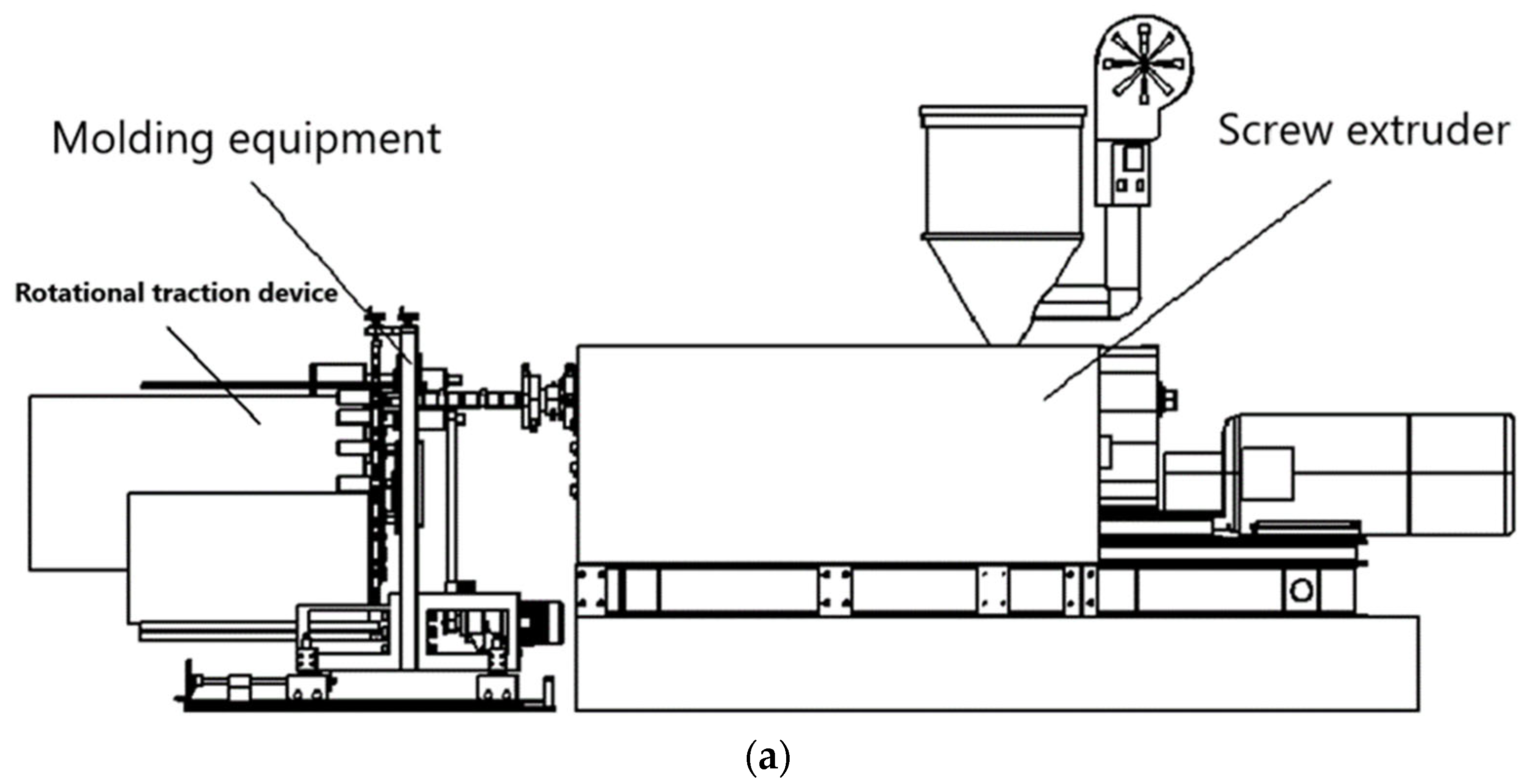
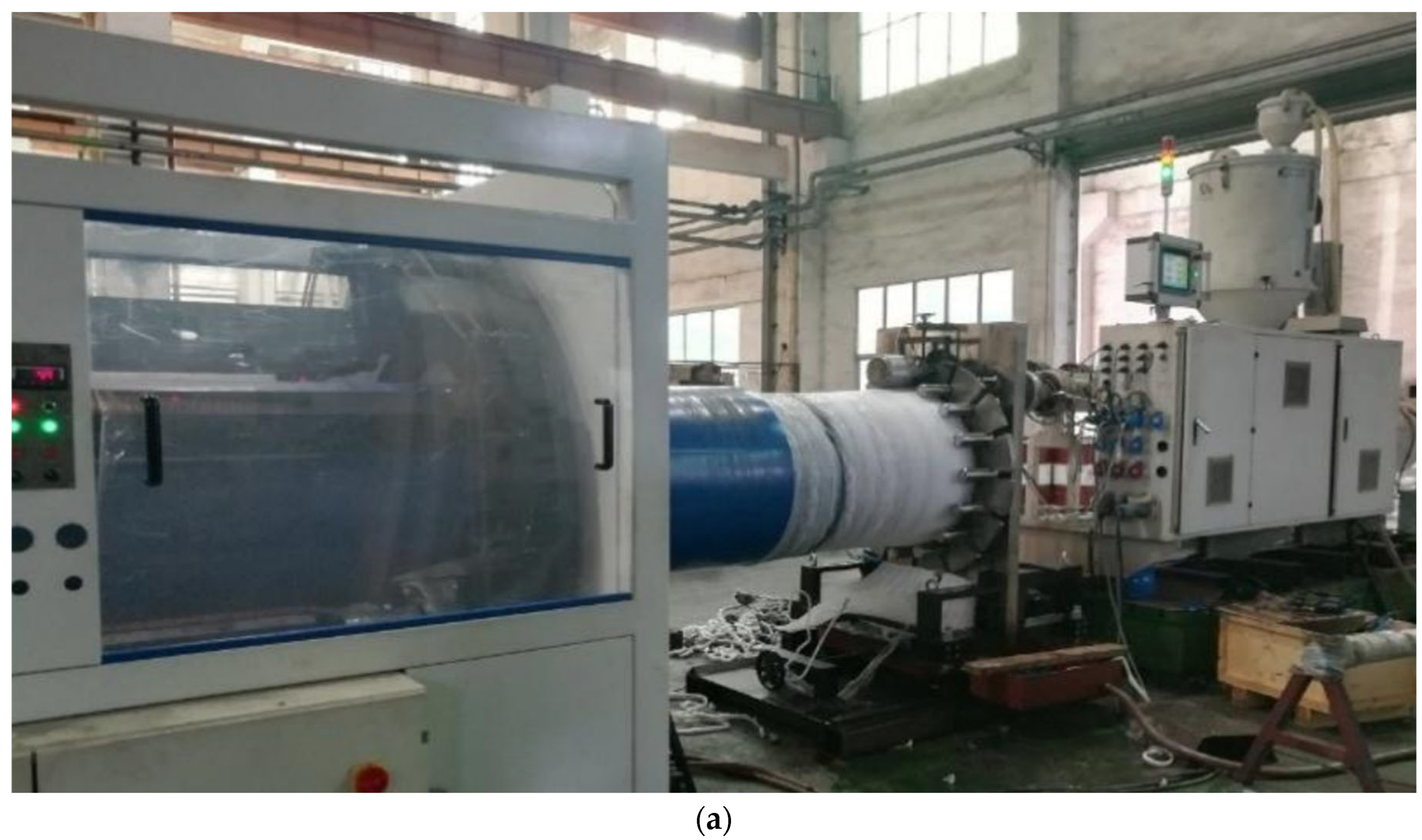
2.2. Manufacturing Method

Polymer melt jetting stacking molding refers to the process in which a molten plastic melt, under a certain temperature and pressure, is injected through a nozzle embedded in the melt [24]. The melt is then spiral-wrapped and accumulated within the space formed by the calendering roll and the backing plate. The local calendering action of the calendering roll ensures that the plastic melt layers are fused together without gaps, ultimately forming continuous, dense, and dimensionally precise pipelines.
The equipment for this molding process consists of a plastic extruder, an embedded feeding nozzle [25], calendering rolls [26], a pipe diameter sizing and adjusting mechanism, a calendering roll drive mechanism, a power device [27], and a framework. By controlling the position of the nozzle, calendering rolls, and the pipe diameter sizing and adjusting mechanism, flexible molding of polymer pipes with multiple diameters can be achieved, as shown in Figure 1.
From Figure 2, The specific workflow is as follows: Firstly, an extruder extrudes molten plastic at a certain temperature with a certain speed and pressure. The molten material flows through a buried nozzle into the space constrained by the rolling mill, guide plate, and pipe blank. The molten material is then rolled and shaped by the rolling mechanism, followed by diameter calibration using the sizing mechanism. Finally, the large-diameter pipe is continuously formed through the rotation of the traction mechanism. The rolling mechanism, diameter calibration mechanism, diameter adjustment mechanism, and rotational traction are all installed on the fixed plate of the frame. The rolling mechanism consists of rolling roller transmission devices. The diameter calibration mechanism consists of inner and outer sizing wheels and restraining springs. The extruder and spray deposition molding device can move relative to each other, enabling adjustment of the nozzle embedding depth.

2.3. Characterization Methods

2.3.1. Tensile Test

Testing Equipment: Desktop Universal Testing Machine, Model 5566, Manufactured by INSTRON Corporation (Canton, High-Tech Corridor 128 in the New England region, MA, USA).
Testing Method [28]: In accordance with the Chinese National Standard [29], a tensile rate of 50 mm/min was used, and the experimental environment was maintained at approximately 23 °C. To ensure accuracy, each experimental group consisted of 5 samples, and the average values were calculated. Following longitudinal elongation or failure of the specimens, parameters including tensile strength and elongation at break were directly obtained through software analysis.
Sampling Method: The sampling process for the pipes requires a minimum of 15 h after production before samples can be taken. The selected pipe is divided into five equal segments along its circumference. From each undamaged segment, several qualified rectangular specimens are cut along both the circumferential and axial directions. These samples have dimensions of 150 mm in length, 10 mm in width, and a thickness of 4 mm.

2.3.2. Impact Test

Testing Instrument: The pendulum impact testing machine used is the POE2000 model, manufactured by INSTRON Company, USA.
Testing Method: The testing procedure follows the guidelines outlined in Chinese National Standard [30]. Specimens are prepared with a prescribed notch at the center. The pendulum impact test is performed on the middle section of the specimen, resulting in a fracture at the notch under the applied impact force. The energy required for fracture is recorded by the instrument. Dividing this energy by the cross-sectional area at the fracture point yields the impact strength. The experiments are conducted at room temperature.
Sampling Method [31]: The samples were obtained from the axial (perpendicular to the helical line) and circumferential (along the helical line) directions on the outer surface of the pipe, 15 h after its formation. Rectangular specimens measuring 80 mm in length, 12 mm in width, and 4 mm in thickness were cut, with a 2 mm deep notch in the width direction. The sampling procedure for the impact specimens is identical to that for the tensile specimens, except for the dimensions of the specimens.

2.3.3. SEM

The macroscopic properties and microstructural variations of the buried jet pile-formed pipeline are influenced by different process parameters. The macroscopic properties can be evaluated through mechanical performance tests, whereas the microstructural changes, such as molecular chain orientation within the pipeline, require analysis using a scanning electron microscope (SEM).
Testing Instrument: A scanning electron microscope, QUANTA FEG250 model, manufactured by FEI Company in the United States.
Testing Method: The formed pipeline is left undisturbed for a minimum of 24 h before samples are extracted from both the circumferential and axial directions for impact testing. The cross-sections of the impact specimens are coated with a thin layer of gold, allowing for observation and imaging of the structure at various magnifications using SEM [32].

3. Result and Discussion

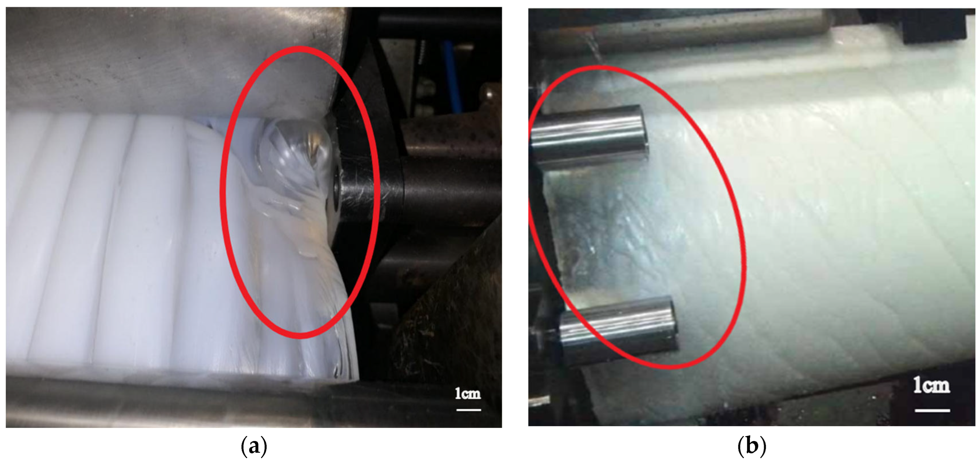
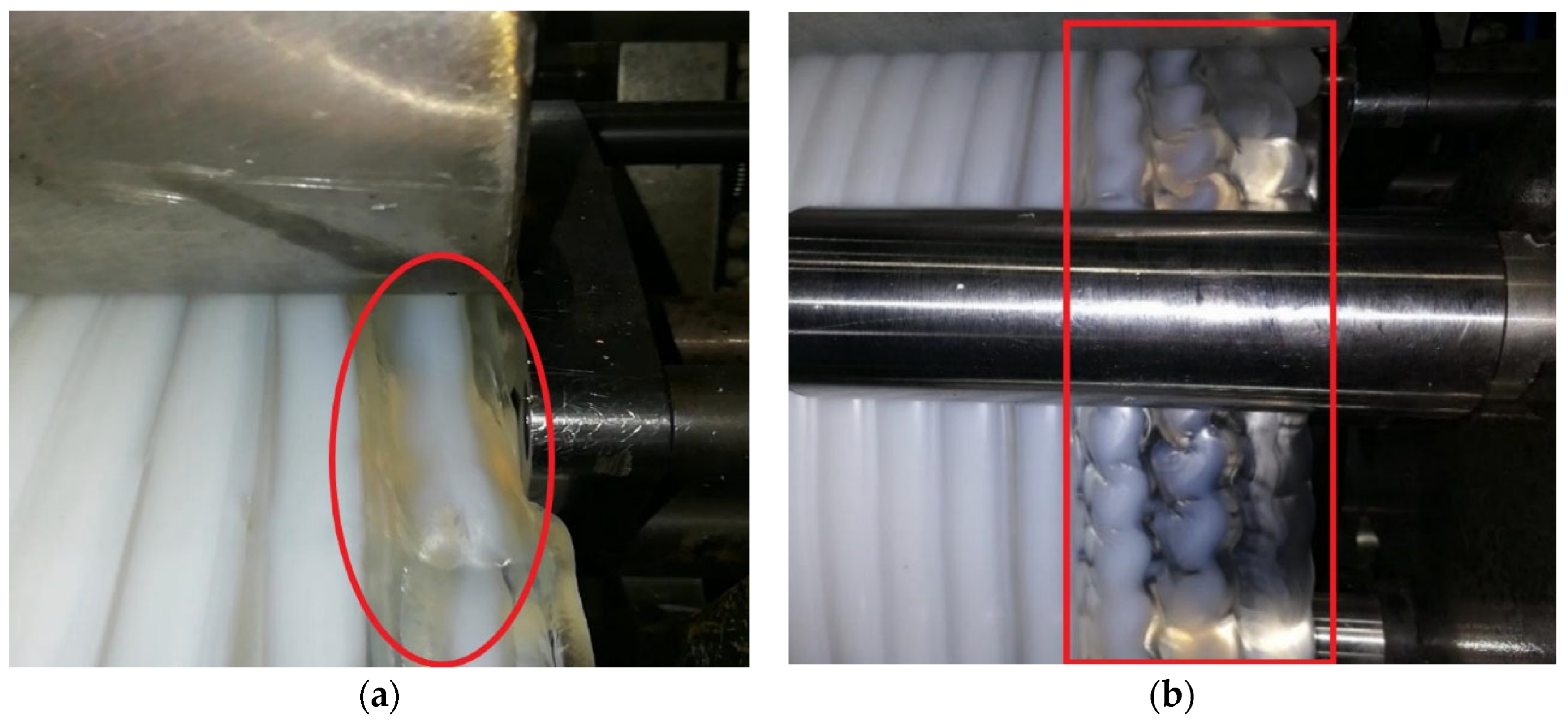
3.1. Influence of Parameters Process on Samples

From Figure 3a shows that the excessively high extrusion rate leads to pipe wrinkling and melt blockage. when the nozzle is embedded in the previous layer of the pipe blank, increasing the nozzle pressure results in higher jet velocity. This leads to a larger reactive force on the calendering roller from the molten material, indicating a greater calendering effect on the molten material. Therefore, under a constant tractive velocity, increasing the extruder speed enables rapid filling of the constrained space by the molten material, reducing heat loss and enhancing the jetting effect with the previous layer of the pipe blank. Consequently, it facilitates fusion between layers of the pipe blank. However, excessive rotational speed should be avoided as it can cause wrinkling or even clogging on the pipe surface due to excessive molten material within the constrained space. Hence, it can be inferred that proper adjustment of the molten material extrusion velocity can improve its impact on the structural performance of the pipe.
In the polymer melt jetting stacking forming process, the temperature of the nozzle’s melt determines its smooth operation. If the temperature is too low, it will cause excessive disturbance when the nozzle is embedded in the previous layer of the pipe blank, resulting in surface quality defects of the formed pipe. On the other hand, if the temperature is too high, a significant amount of cooling medium is required for cooling. During the forming process, the melt just ejected from the nozzle is in a viscous-flow state, while the previous layer of the pipe blank, after rotating for one revolution, is in a near-molten state due to cooling. This allows the nozzle to be embedded in the previous layer of the pipe blank and use its own heat to jet and stack the melt, forming the pipe. The pipe blank in the near-molten state, after being calendered and sized by the calendering roller and sizing roller, needs to be rapidly cooled and solidified. If the cooling is not timely, the partially cooled and solidified pipe blank may detach from the calendering roller and sizing roller, leading to uneven shrinkage and affecting the surface quality, as shown in Figure 3b.
When the extrusion rate is constant, reducing the tractive velocity not only increases the depth of nozzle embedding in the previous layer of the pipe blank but also results in denser stacking between layers, to some extent reducing the helix pitch. However, if the tractive velocity is too slow, it can lead to wrinkling or even material blockage, as shown in Figure 4a. This is because the nozzle is excessively embedded, severely damaging the surface structure of the previous layer of the pipe blank, and the constrained space becomes smaller, causing material accumulation. Increasing the tractive velocity, on the other hand, reduces the depth of nozzle embedding in the previous layer of the pipe blank and results in looser stacking between layers, as shown in Figure 4b. This to some extent increases the helix pitch. However, if the tractive velocity is too high, it not only reduces the wall thickness of the formed pipe but also causes uneven flow.
When the rolling speed is less than 3.5 rpm, it not only weakens the circumferential shearing force exerted on the pipe during the forming process but also affects the timely fusion of the newly extruded melt with the previous layer of the pipe blank, potentially causing surface slant and defects, as shown in Figure 5a. On the other hand, When the rolling speed approaches 5.5 rpm, it increases the circumferential shearing force on the pipe and enhances the circumferential orientation. This allows for rapid fusion between the newly extruded melt and the previous layer of the pipe blank, reducing heat loss during the fusion between layers. However, when the rolling speed exceeds 6 rpm, it increases the load and energy consumption during the rotation of the rolling roller, and may even lead to relative sliding between the rolling roller and the pipe blank, resulting in uneven surface and wrinkling of the pipeline, as shown in Figure 5b. Therefore, it is not advisable to simply increase the rolling speed to enhance the circumferential strength of the pipe by increasing the circumferential shearing force it experiences.

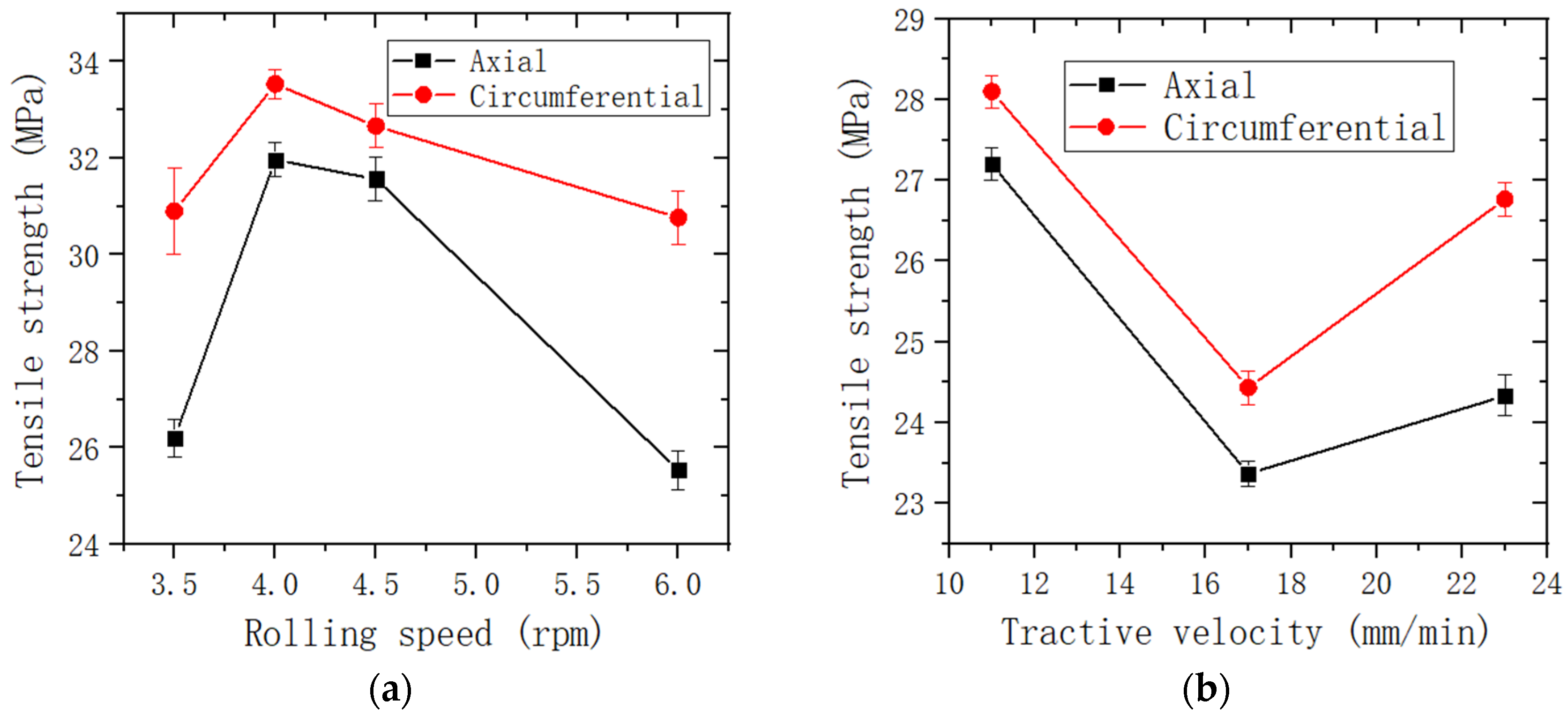
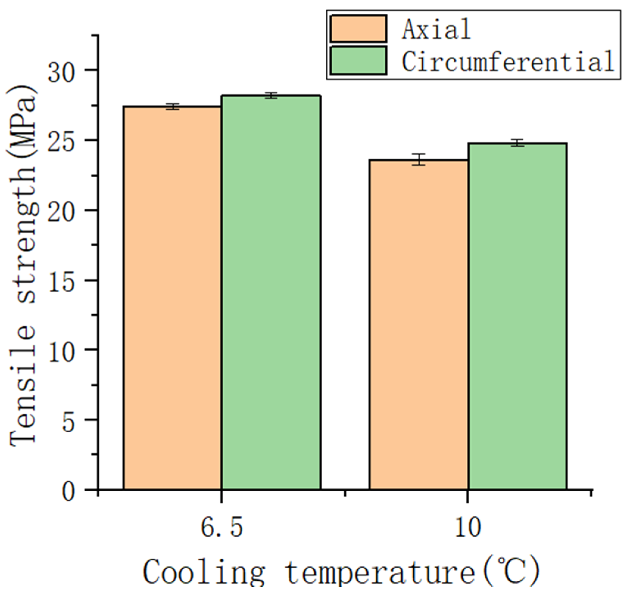
3.2. Tensile Properties

Increasing the rolling speed can increase the shear stress exerted on the melt, and the increased axial velocity of the melt in the pipe is beneficial for the fusion between layers, which will inevitably affect the mechanical properties of the product. As observed in Figure 6a, with the increase in rolling speed, the tensile strength of the pipe initially increases and then decreases, indicating that the rolling speed has a certain influence on the tensile strength of the pipe, with a relatively high tensile strength at 4.0 rpm. At the same rolling frequency, the circumferential tensile strength of the pipe is higher than the axial tensile strength, indicating that this forming process can improve the circumferential tensile performance of the pipe, which is beneficial for achieving self-reinforcement of the pipe and improving its utility.
From Figure 6b, with the increase in tractive velocity, the tensile strength of the pipe first decreases and then increases, showing an overall decreasing trend. However, the effect of tractive velocity on the tensile strength of the pipe is not significant. Moreover, under the same tractive velocity, the circumferential tensile strength of the pipe is slightly higher than the axial tensile strength, but the difference between the two is not significant. This indicates that the circumferential and axial tensile properties of pipe are relatively uniform and can improve the utility of the pipe material.
The experimental parameters were set as the lower cooling temperatures of 6.5 °C and 10 °C to investigate the influence of different cooling temperatures on the tensile performance of the pipes. From Figure 7, with the increase in cooling and shaping temperature, the tensile strength of the pipe tends to decrease. This is mainly because the cooling and shaping temperature affects the crystallinity and aggregation structure of HDPE. Furthermore, under the same cooling and shaping temperature, the circumferential tensile strength of the pipe is higher than the axial tensile strength, with a negligible difference. This indicates that the circumferential and axial tensile properties of the pipe are uniform, which is conducive to improving the utility of the pipe material.

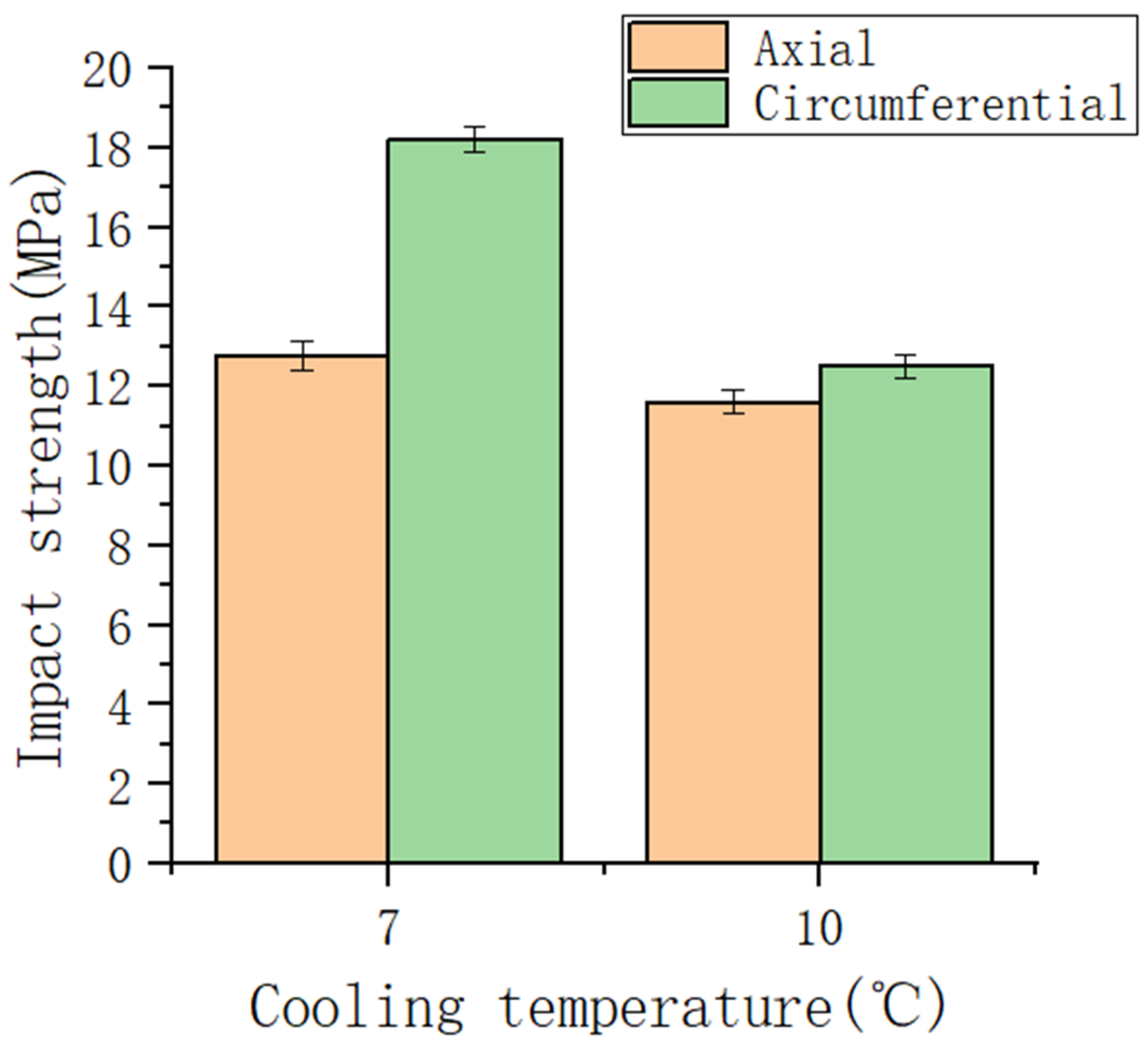
3.3. Impact Strength
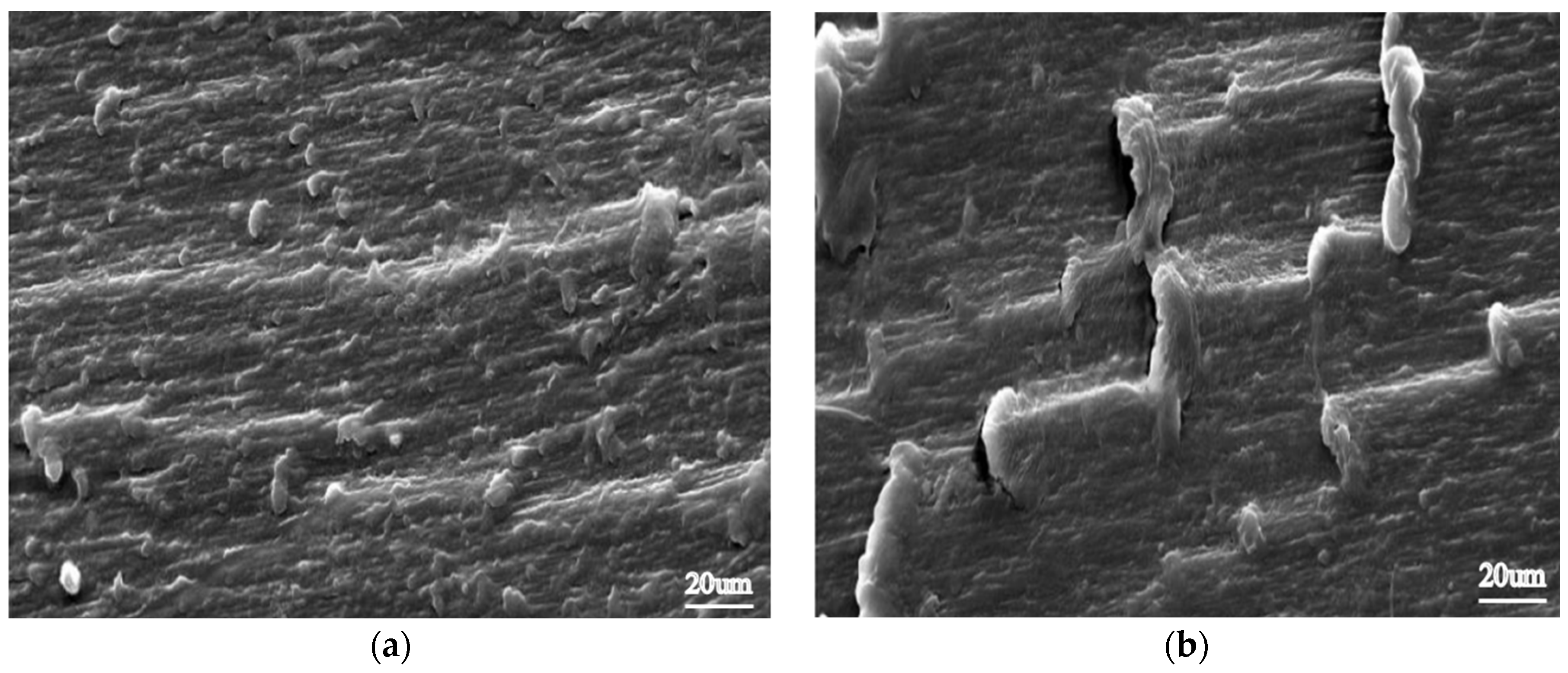
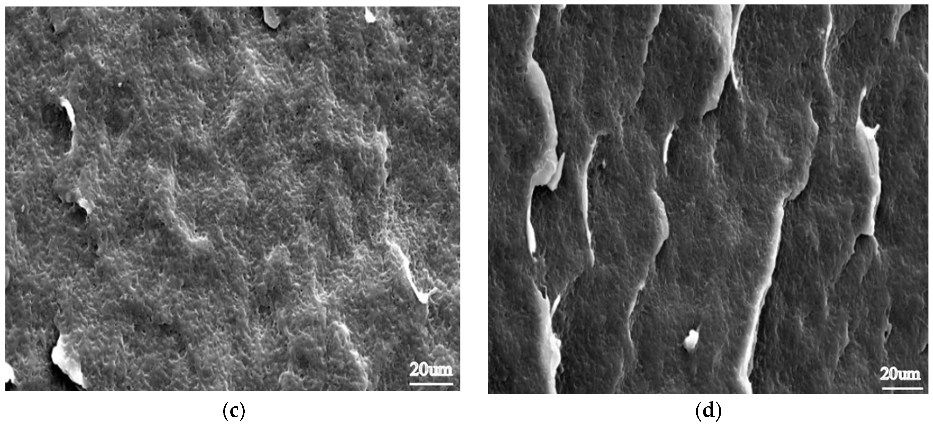
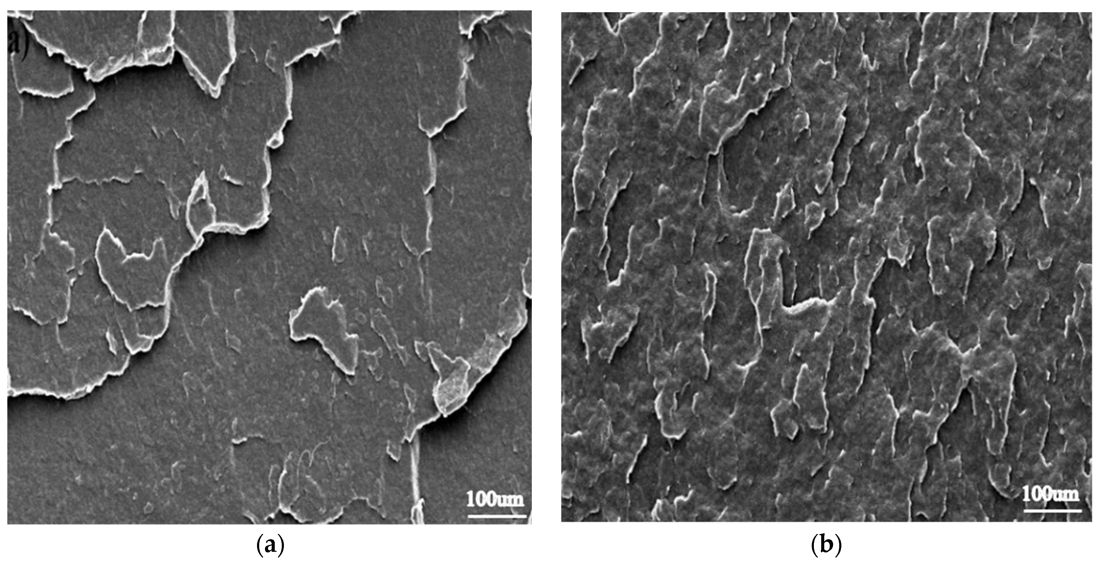
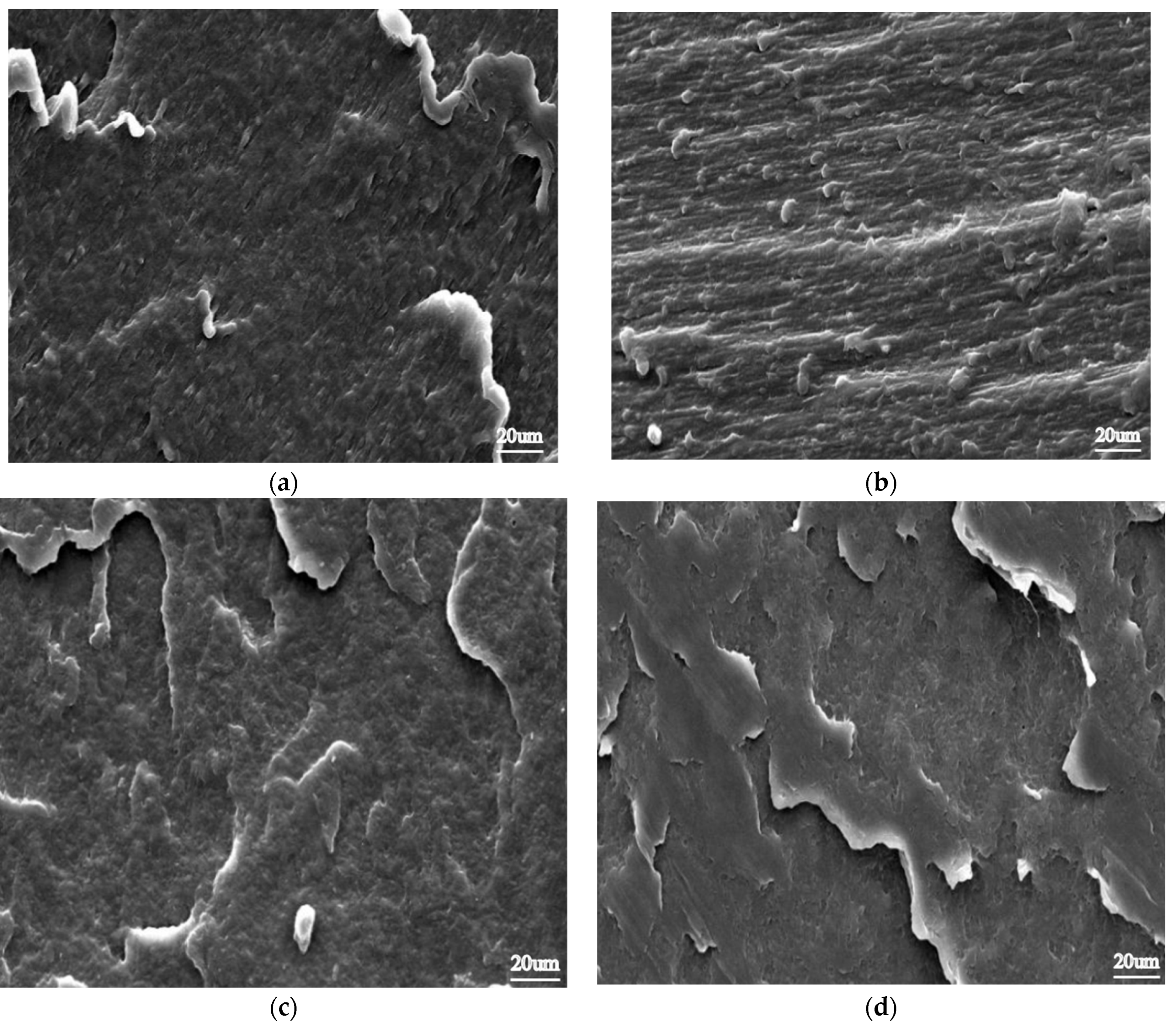
From Figure 8a, with the increase in rolling speed, the impact strength of the pipe increases. Moreover, under the same rolling speed, the circumferential impact strength of the pipe is higher than the axial impact strength. This indicates that the rolling speed has a significant influence on the impact strength of the pipe under the action of rolling. From the perspective of improving the impact performance of the pipe, the impact strength of the pipe material can be enhanced by increasing the rolling speed.
From Figure 8b, with the increase in tractive velocity, the impact strength of the pipe initially decreases and then increases, showing an overall decreasing trend. Furthermore, under the same tractive velocity, the circumferential impact strength of the pipe is higher than the axial impact strength, with a significant difference. This indicates that the circumferential impact strength of the pipe can be greatly improved, which is beneficial for enhancing the utility of the pipe material, especially its circumferential impact resistance. This is particularly important for large-diameter pipelines, especially buried pipelines.
The melting behavior of pipes varies under different cooling temperatures, inevitably affecting their mechanical performance. With the experimental parameters of lower cooling temperatures, specifically 7 °C and 10 °C, an investigation was conducted to explore the impact of different cooling temperatures on the performance of the pipes. From Figure 9, the influence of different cooling and shaping temperatures on the circumferential and axial impact strength of the pipe shows that as the cooling and shaping temperature increases, the overall impact strength of the pipe slightly decreases. This is because the higher cooling temperature helps the molecular chains to fully stretch, improving the crystallinity inside the pipe. However, the increase in crystallinity tends to decrease the impact strength, which is consistent with the analysis of tensile strength results. Additionally, when analyzing under the same cooling and shaping temperature, it can be seen that the circumferential impact strength of the pipe is higher than the axial impact strength. This indicates that the pipe exhibits excellent circumferential impact resistance.

3.4. Microstructure

By comparing Figure 10a,c with Figure 10b,d, there are significant differences in the circumferential and axial structures of the formed pipe under the same cooling and shaping temperature. The images in Figure 10a,b exhibit clear orientation, indicating that the pipe has a higher degree of circumferential orientation than axial orientation. This is consistent with the comparison results of the circumferential and axial tensile strengths of the formed pipe under the same cooling and shaping temperature. The orientation in Figure 10a is more pronounced than in Figure 10b, while Figure 10d appears denser than Figure 10c. This is because the higher cooling and shaping temperature allows for a more thorough crystallization of the pipe and produces a stronger, tighter bond between layers through spray deposition. It can be concluded that by setting the cooling temperature, the melt temperature and temperature distribution can be controlled to affect the internal crystalline structure of the pipe, thereby influencing its mechanical properties.
From Figure 11, the internal structure of the formed pipe varies with different tractive velocities. Specifically, at low tractive velocities (10 mm/min), the internal structure, especially the axial structure, is more compact, while at high tractive velocities (22 mm/min), the axial structure appears more porous. This is because, under constant other process parameters, a lower tractive velocity allows the nozzle to penetrate deeper into the previous layer of the pipe blank, facilitating spray deposition and better fusion between layers. On the other hand, excessive tractive velocity can result in shallow or no penetration of the nozzle into the previous layer of the pipe blank, which hinders the spray deposition between layers and leads to less effective fusion.
By comparing Figure 12a,b with Figure 12c,d, it is evident that as the rolling speed increases, the circumferential orientation of the pipe section is enhanced while the axial section becomes denser. Furthermore, by comparing Figure 12a,c with Figure 12b,d, significant differences in the circumferential and axial sections of the pipe are observed under the same rolling speed. The circumferential section exhibits clear orientation, whereas no apparent orientation is observed in the axial section. This is because the pipe has a higher degree of circumferential orientation than axial orientation. Moreover, with the increased rolling speed, the circumferential section experiences greater shear forces, resulting in a more pronounced orientation. This promotes faster spray deposition of the freshly ejected molten plastic onto the previous layer of the pipe blank, reducing heat loss and ensuring a stronger and denser fusion between layers.

4. Conclusions

A polymer melt jetting stacking device can achieve the formation of PE pipes with a diameter of 780 mm and a wall thickness of 20 mm. Under the conditions of a rolling speed ranging from 3.0 to 6.0 rpm, a tractive velocity ranging from 10 to 24 mm/min, and a cooling temperature ranging from 6.5 to 11 °C, mechanical performance tests have shown that the tensile strength initially increased with an increase in the rolling speed, followed by a subsequent decrease, albeit with marginal differences. The overall trend in tensile strength with an increase in the tractive velocity was a gradual decrease, despite an initial decline and subsequent rise. Additionally, the tensile strength exhibited a decreasing trend with an increase in the forming temperature. In terms of impact strength, there was an increasing trend observed with an increase in the rolling speed. The tractive velocity initially showed a decrease, followed by an increase, but displayed an overall decreasing trend. Moreover, the impact strength demonstrated a decreasing trend with an increase in the forming temperature. The circumferential mechanical properties exhibited superiority over the axial mechanical properties.
The influence of forming process conditions on the microstructure of pipe products was investigated through SEM testing. The results showed that the microstructure morphology became more orderly and denser with the increase in rolling speed, while it was less affected by tractive velocity and forming temperature. This consistency with the variation of mechanical properties of pipe products during the spray deposition process suggests that the microstructure is closely related to the process parameters. Additionally, the circumferential orientation of the pipes was found to be higher than the axial orientation.
The polymer melt jetting stacking process is influenced by various process parameters, and the adjustment of these parameters has a significant impact on the microstructure and performance of the pipes. Important process parameters such as melt extrusion speed, rolling speed, and cooling temperature directly affect the quality of pipe formation. By improving the precision of control over these process parameters, the quality of pipe formation can be enhanced.
Polymer melt jetting stacking does not require molds, but it imposes strict requirements on temperature and speed control. This necessitates the use of auxiliary equipment such as forming devices and rotating traction machines to achieve precise control. The optimization of auxiliary equipment design is one of the directions for the development of this molding technology. Additionally, since the essence of this molding method is spiral stacking, where the melt undergoes a spiral motion during the forming process, the resulting pipe is a spiral pipe. Therefore, improving the quality of the inner wall of the pipe is also an area for improvement in this technology.

Author Contributions

The presented work was under supervision by Y.Z. and S.W.; Y Z. and S.W.: conceptualization, software, and writing—original draft; S.W.: validation, writing—review and editing; Y.Z. and W.Z.: investigation and editing; W.Z.: Validation. All authors have read and agreed to the published version of the manuscript.

Funding

1. 2022 Guangdong Provincial Undergraduate Teaching Quality and Teaching Reform Engineering Project (Yuejiaogao Han (2023) No. 4): Excellent Intelligent Manufacturing Special Talent Training Program Project; 2. National Natural Science Foundation of China: 52075541.

Institutional Review Board Statement

Not applicable.

Informed Consent Statement

Not applicable.

Data Availability Statement

This study did not report any data.

Acknowledgments

The authors acknowledge the editors and reviewers for their constructive comments and all the support with this work.

Conflicts of Interest

The authors declare no conflict of interest.

References

  1. Walsh, T. The plastic piping industry in North America. In Applied Plastics Engineering Handbook; William Andrew Publishing: Norwich, NY, USA, 2011; pp. 585–602. [Google Scholar] [CrossRef]
  2. Jiang, L.; Zhang, S.; Wang, Y.; Feng, Y.; Lin, Y.; Liu, H.; Zhang, F.; Shao, H. Research on bending forming method of large diameter-thickness ratio thin-walled tubes for aerospace. Int. J. Adv. Manuf. Technol. 2019, 102, 3037–3049. [Google Scholar] [CrossRef]
  3. Clutton, E.Q.; Williams, J.G. On the measurement of residual stress in plastic pipes. Polym. Eng. Sci. 1995, 35, 1381–1386. [Google Scholar] [CrossRef]
  4. Wang, Y.Q.; Bu, C.; Hou, X.; Du, J. Automatic winding forming technology for manufacturing Glass Fiber Reinforced Plastic pipes. In Proceedings of the 2021 4th World Conference on Mechanical Engineering and Intelligent Manufacturing (WCMEIM), Shanghai, China, 12–14 November 2021; IEEE: Piscataway, NJ, USA, 2021; pp. 665–668. [Google Scholar]
  5. Prinsloo, K.; Webb, M.; Wrigglesworth, M. Advancement of condition assessment technicques for large diameter pipelines. Civ. Eng. Mag. S. Afr. Inst. Civ. Eng. 2001, 19, 20–25. [Google Scholar]
  6. Chokshi, R.; Zia, H. Hot-melt extrusion technique: A review. Iran. J. Pharm. Res. 2004, 3, 3–16. [Google Scholar]
  7. Šoštarić, D.; Samardžić, I.; Pintarić, A. Quality monitoring at fusion welding of polyethylene high-density pipes. Metalurgija 2012, 51, 505–508. [Google Scholar]
  8. Saengow, C.; Giacomin, A.J.; Kolitawong, C. Knuckle formation from melt elasticity in plastic pipe extrusion. J. Non-Newton. Fluid Mech. 2017, 242, 11–22. [Google Scholar] [CrossRef]
  9. Zhang, J.; Li, T.; Chu, L.; Bi, D.S. The Die Design of Large Diameter Tee Multi-Pass Extrusion Process. Adv. Mater. Res. 2011, 194, 2199–2203. [Google Scholar] [CrossRef]
  10. Chen, M.; Weng, Y.; Semple, K.; Zhang, S.; Jiang, X.; Ma, J.; Fei, B.; Dai, C. Sustainability and innovation of bamboo winding composite pipe products. Renew. Sustain. Energy Rev. 2021, 144, 110976. [Google Scholar] [CrossRef]
  11. Xu, J.; Yang, H.; Liu, M.; Tian, J.; Liu, B. Research on winding trajectory planning for elbow pipe based on industrial robot. Int. J. Adv. Manuf. Technol. 2017, 93, 537–545. [Google Scholar] [CrossRef]
  12. Chang, C.; Han, Z.; Li, X.; Sun, S.; Qin, J.; Fu, H. A non-geodesic trajectory design method and its post-processing for robotic filament winding of composite tee pipes. Materials 2021, 14, 847. [Google Scholar] [CrossRef]
  13. Zou, W.; Chen, R.; Zhang, G.; Zhang, H.; Qu, J. Mechanical, thermal and rheological properties and morphology of poly (lactic acid)/poly (propylene carbonate) blends prepared by vane extruder. Polym. Adv. Technol. 2016, 27, 1430–1437. [Google Scholar] [CrossRef]
  14. Howell, G.M.; Gates, J.G.; Gates, J.C.C. Laminated Plastic Pipe. U.S. Patent 2888954, 2 June 1959. [Google Scholar]
  15. Levingston, J.C.; Beasley, J.K. Pipe Extrusion Process. U.S. Patent 6488802B1, 3 December 2002. [Google Scholar]
  16. Hegler, W. Method of Producing Plastic Tubing Having a Corrugated Outer Wall. U.S. Patent 3538209A, 3 November 1970. [Google Scholar]
  17. Wickramasinghe, S.; Do, T.; Tran, P. FDM-based 3D printing of polymer and associated composite: A review on mechanical properties, defects and treatments. Polymers 2020, 12, 1529. [Google Scholar] [CrossRef]
  18. Hong, S.; Lee, S.; Kim, N. A parametric study on forming length in roll forming. J. Mater. Process. Technol. 2001, 113, 774–778. [Google Scholar] [CrossRef]
  19. Cooreman, S.; Van Hoecke, D.; Liebeherr, M.; Thibaux, P.; Yamaguti Enderlin, M. Experimental and numerical study on the evolution of mechanical properties during spiral pipe forming. In Proceedings of the International Pipeline Conference, Calgary, AB, Canada, 26–30 September 2016; American Society of Mechanical Engineers: New York, NY, USA, 2016. [Google Scholar]
  20. Sohn, S.S.; Han, S.Y.; Bae, J.H.; Kim, H.S.; Lee, S. Effects of microstructure and pipe forming strain on yield strength before and after spiral pipe forming of API X70 and X80 linepipe steel sheets. Mater. Sci. Eng. A 2013, 573, 18–26. [Google Scholar] [CrossRef]
  21. Bui, Q.V.; Ponthot, J.P. Numerical simulation of cold roll-forming processes. J. Mater. Process. Technol. 2008, 202, 275–282. [Google Scholar] [CrossRef]
  22. Yun, X.B.; Wei, Y.O.U.; Ying, Z.H.A.O.; Bing, L.I.; Fan, Z.X. Continuous extrusion and rolling forming velocity of copper strip. Trans. Nonferrous Met. Soc. China 2013, 23, 1108–1113. [Google Scholar] [CrossRef]
  23. Hsuan, Y.G.; McGrath, T.J. HDPE Pipe: Recommended Material Specifications and Design Requirements; Transportation Research Board: Washington, DC, USA, 1999. [Google Scholar]
  24. Raju, G.; Sharma, M.L.; Meena, M.L. Recent methods for optimization of plastic extrusion process: A literature review. Int. J. Adv. Mech. Eng. 2014, 4, 583–588. [Google Scholar]
  25. Zaman, P.B.; Dhar, N.R. Design and evaluation of an embedded double jet nozzle for MQL delivery intending machinability improvement in turning operation. J. Manuf. Process. 2019, 44, 179–196. [Google Scholar] [CrossRef]
  26. Jani, R.; Patel, D. Hot melt extrusion: An industrially feasible approach for casting orodispersible film. Asian J. Pharm. Sci. 2015, 10, 292–305. [Google Scholar] [CrossRef] [Green Version]
  27. Adolph, K.E.; Franchak, J.M. The development of motor behavior. Wiley Interdiscip. Rev. Cogn. Sci. 2017, 8, e1430. [Google Scholar] [CrossRef] [Green Version]
  28. Dexter, A.R.; Watts, C.W. Tensile strength and friability. Soil Environ. Anal. Phys. Methods 2000, 2, 405–433. [Google Scholar]
  29. GB/T 19472.2-2004; Polyethylene Structure-Wall Piping System for Underground Usage Part 2: Polyethylene Spirally Enwound Structure-Wall Pipes. Industrial Standards Committee: Beijing, China, 2004.
  30. GB/T1843-2008; Plastics—Determination of Izod Impact Strength. Industrial Standards Committee: Beijing, China, 2008.
  31. Liu, F.; Feng, W.; Xiong, Z.; Li, L.; Yang, Y.; Lin, H.; Shen, Y. Impact performance of new prestressed high-performance concrete pipe piles manufactured with an environmentally friendly technique. J. Clean. Prod. 2019, 231, 683–697. [Google Scholar] [CrossRef]
  32. Wang, H.; Yu, Y.; Yu, J.; Duan, J.; Zhang, Y.; Li, Z.; Wang, C. Effect of 3D random pitting defects on the collapse pressure of pipe—Part I: Experiment. Thin-Walled Struct. 2018, 129, 512–526. [Google Scholar] [CrossRef]
Figure 1. The device of polymer melt jetting stacking molding: (a) the whole device; (b) the molding device.
Processes 11 02384 g001aProcesses 11 02384 g001b
Figure 2. The manufacturing process of polymer melt jetting stacking molding: (a) experimental pipe formation; (b) backside of the forming machine; (c) calendering rolls for pipe rolling.
Processes 11 02384 g002aProcesses 11 02384 g002b
Figure 3. (a) Influence of extruder speed on the sample; (b) influence of temperature on the sample.
Processes 11 02384 g003
Figure 4. Influence of tractive velocity on the sample; (a) influence of excessive speed on the sample; (b) influence of insufficient speed on the sample.
Processes 11 02384 g004
Figure 5. Influence of rolling speed: (a) influence of a rolling speed less than 3.5 rpm on the sample; (b) influence of a rolling speed exceeding 6 rpm on the sample.
Processes 11 02384 g005
Figure 6. (a) The relationship between rolling speed and tensile strength; (b) the relationship between tractive velocity and tensile strength.
Processes 11 02384 g006
Figure 7. The relationship between cooling temperature and tensile strength.
Processes 11 02384 g007
Figure 8. (a) the relationship between rolling speed and impact strength; (b) the relationship between tractive velocity and impact strength.
Processes 11 02384 g008
Figure 9. The relationship between the cooling temperature and impact strength.
Processes 11 02384 g009
Figure 10. (a) Microstructural characteristics in the circumferential orientation at room temperature; (b) microstructural characteristics in the circumferential orientation at 6 °C; (c) microstructural characteristics in the axial direction at room temperature; (d) microstructural characteristics in the axial direction at 6 °C.
Processes 11 02384 g010aProcesses 11 02384 g010b
Figure 11. Microstructural characteristics in the axial direction at different tractive velocities: (a) 12 mm/min; (b) 17 mm/min.
Processes 11 02384 g011
Figure 12. (a) Microstructural characteristics in the circumferential orientation at 2.5 rpm; (b) microstructural characteristics in the circumferential orientation at 8.5 rpm; (c) microstructural characteristics in the axial direction at 2.5 rpm; (d) microstructural characteristics in the axial direction at 8.5 rpm.
Processes 11 02384 g012
Table 1. The characteristics of conventional techniques for large-diameter pipes.
Mechanical PropertiesAxialCircumferential
Tensile strength24.04 MPa27.84 MPa
Impact strength8.40 kJ/m28.97 kJ/m2
Table 2. Physical properties of HDPE.
Physical ParametersValues
Density (ρ) g/cm30.956
Melt flow rate (MFR) g/10 min0.04
Non-Newtonian index (n)0.54
Infinite shear viscosity (η∞) pa s0
Zero shear viscosity (η0) pa s2100
Relaxation time (λ) s0.07
Thermal conductivity (k) W/(m k)0.461
Specific heat capacity (Cp) J/(kg k)2203
Disclaimer/Publisher’s Note: The statements, opinions and data contained in all publications are solely those of the individual author(s) and contributor(s) and not of MDPI and/or the editor(s). MDPI and/or the editor(s) disclaim responsibility for any injury to people or property resulting from any ideas, methods, instructions or products referred to in the content.

