Article

Enhanced Oil Recovery and CO2 Storage Performance in Continental Shale Oil Reservoirs Using CO2 Pre-Injection Fracturing

1
School of Economics and Management, China University of Geosciences, Beijing 100083, China
2
Key Laboratory of Carrying Capacity Assessments for Resources and Environment, Ministry of Natural Resources of the People’s Republic of China, Beijing 100083, China
3
The College of Economics and Management, Beijing University of Chemical Technology, Beijing 100029, China
4
PetroChina Research Institute of Petroleum Exploration & Development, Beijing 100083, China
*
Authors to whom correspondence should be addressed.
Processes 2023, 11(8), 2387; https://doi.org/10.3390/pr11082387
Submission received: 1 July 2023 / Revised: 27 July 2023 / Accepted: 3 August 2023 / Published: 8 August 2023

Abstract

:
CO2 pre-injection fracturing is a promising technique for the recovery of continental shale oil. It has multiple advantages, such as oil recovery enhancement, CO2 geological storage and water consumption reduction. Compared with conventional CO2 huff and puff and flooding, CO2 pre-injection features higher injection rates and pressures, leading to EOR and improved CO2 storage performance. Combining physical experiments and numerical simulation, this research systematically investigated the EOR and storage performance of CO2 pre-injection in continental shale reservoirs. The results showed that CO2 pre-injection greatly improved the oil recovery; after seven cycles of soaking, the average oil recovery factor was 39.27%, representing a relative increase of 31.6% compared with that of the conventional CO2 huff and puff. With the increasing pressure, the CO2 solubility grew in both the oil and water, and so did the CO2 adsorption in shale. Numerical simulation indicated that the average CO2 storage ratio of the production stage was 76.46%, which validated the effectiveness of CO2 pre-injection in terms of CO2 geological storage.

1. Introduction

The Intergovernmental Panel on Climate Change (IPCC) of the United Nations reports that limiting global warming to 2 °C requires the global artificial carbon dioxide (CO2) emissions to be reduced by a quarter compared with those in 2010 before 2030 at the latest and achieve net zero CO2 emissions by 2075; for a more rigorous goal of 1.5 °C, net zero CO2 emissions need to be achieved globally by 2050 [1]. Besides promoting applications of techniques of energy-saving, carbon emission reduction and renewable energy, CO2 capture, utilization and storage (CCUS) is also one of the effective approaches to deliver net zero CO2 emissions [2,3,4]. In the context of China’s clearly stated goals of carbon peak and neutrality, CCUS becomes increasingly important for China.
Geological sites applicable to CO2 storage include saline aquifers, unrecoverable coal seams, and oil and gas reservoirs [5,6,7,8,9]. CO2-EOR projects performed in oil and gas reservoirs deliver both the social benefits of carbon reduction and economic benefits to stimulated hydrocarbon production. Moreover, such projects are highly feasible due to the available existing well sites and equipment, and thus, become preferred choices for the geological storage of CO2 [10,11,12,13,14]. By far, the CO2-EOR in conventional oil and gas reservoirs has reached the stage of industrial demonstration, where demonstration projects with a capacity of up to 100,000 tons have been successively accomplished in the Daqing, Jilin and Shengli oilfields. CO2 features unique physical and chemical properties. Under the formation temperature and pressure, it is typically supercritical, with an extremely strong diffusion capacity to enter micro-nano pores of rocks and harvest crude oil beyond the reach of conventional EOR methods. Furthermore, supercritical CO2 can extract light components of crude oil and improve oil mobility [15,16,17]. As CO2 and crude oil mix, plenty of CO2 dissolves into oil, which considerably reduces the oil viscosity and enhances oil recovery via various mechanisms, such as the resultant crude oil volume expansion and miscibility between oil and CO2. Besides the above-stated, CO2 is clean and environment-friendly. It has great application potential in the exploration and development of unconventional hydrocarbon resources [18,19,20,21,22].
CO2 huff and puff demands a miscible state between CO2 and formation crude oil to maximize the recovery factor [23,24,25,26]. However, the shale oil plays of China are mainly continental [27,28,29], the miscibility pressure of crude oil is high and miscible flooding cannot be delivered; in some shale oil reservoirs, the minimum miscibility pressure (MMP) is even higher than the formation pressure. Even in shale oil reservoirs with the MMP lower than the bottomhole pressure, CO2 flooding is still faced with the challenge that miscibility can only be delivered in the near-wellbore zone and the consequently restrained EOR performance due to the limits of the reservoir’s physical properties, crude oil properties, equipment capacity and technical schemes [30,31]. Given the aforementioned, the EOR technique based on CO2 pre-injection was proposed to take full advantage of CO2 in EOR. Specifically, CO2 is injected into the reservoir at high injection pressures and high pump rates during fracturing to keep the formation pressure above the miscibility pressure over a rather long period, expand the swept zone of CO2 and ultimately enhance the recovery factor of shale oil.
Extensive studies have been carried out to investigate the mechanisms and sequestration effects of CO2-EOR with low injection pressures and rates. However, the EOR and sequestration mechanisms of CO2 pre-injection during fracturing are less researched [32,33,34]. Therefore, this research systematically investigated the interaction mechanisms between CO2 and crude oil in the case of high-pressure fracturing of continental shale oil reservoirs via laboratory experiments. It shall be noted that the experiments stated below were all performed at high pressure. Furthermore, the storage performance of CO2 pre-injection at the field scale was analyzed via numerical simulation. The findings of this research validate the effectiveness of EOR and sequestration of CO2 pre-injection during fracturing in continental shale oil reservoirs and provide theoretical support for applications of this technique in shale oil recovery.

2. Experimental Section

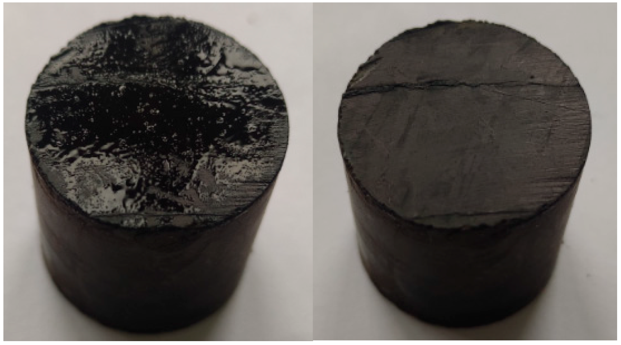
2.1. Sample Preparation

The shale samples used in this research were collected from the Qingshankou Formation in the Songliao Basin, China. The Qingshankou Formation is predominated by mudstone-shale, with localized occurrence of interbeds of sandstone, limestone and limy mudstone. Mudstone-shale is mainly composed of quartz, clay minerals, feldspar and carbonate minerals, and clay minerals account for about 30–60%. The content of brittle minerals is relatively high, and micropores and microfractures are well developed. This area is one of China’s major plays of continental shale and possesses geological resources of shale oil of about 54.6 × 10⁸ t, which shows extremely high potential for exploration and development [35,36].
The depth of the Qingshankou Formation shale reservoir is about 1800–2400 m. The first section of the Qingshankou Formation is the current focus of shale oil recovery and has a formation temperature of 90 °C–110 °C. The experimental temperature was set to 90 °C for all experiments of this research as per the comprehensive consideration of the formation conditions and experimental apparatus capacity. The formation water salinity was determined via tests of produced water (Table 1).
The drill cores were made into cylinders with the dimensions of 5 cm × Φ2.5 cm via a wire-cutting process. Then, the cylindrical specimens with intact appearance and no notable cracking were selected and polished using abrasive paper to ensure smooth end and side surfaces. The polished cylinders were then put through an oil removal process, which was performed with caution to avoid damage to the core specimens. The prepared core specimens are presented in Figure 1.

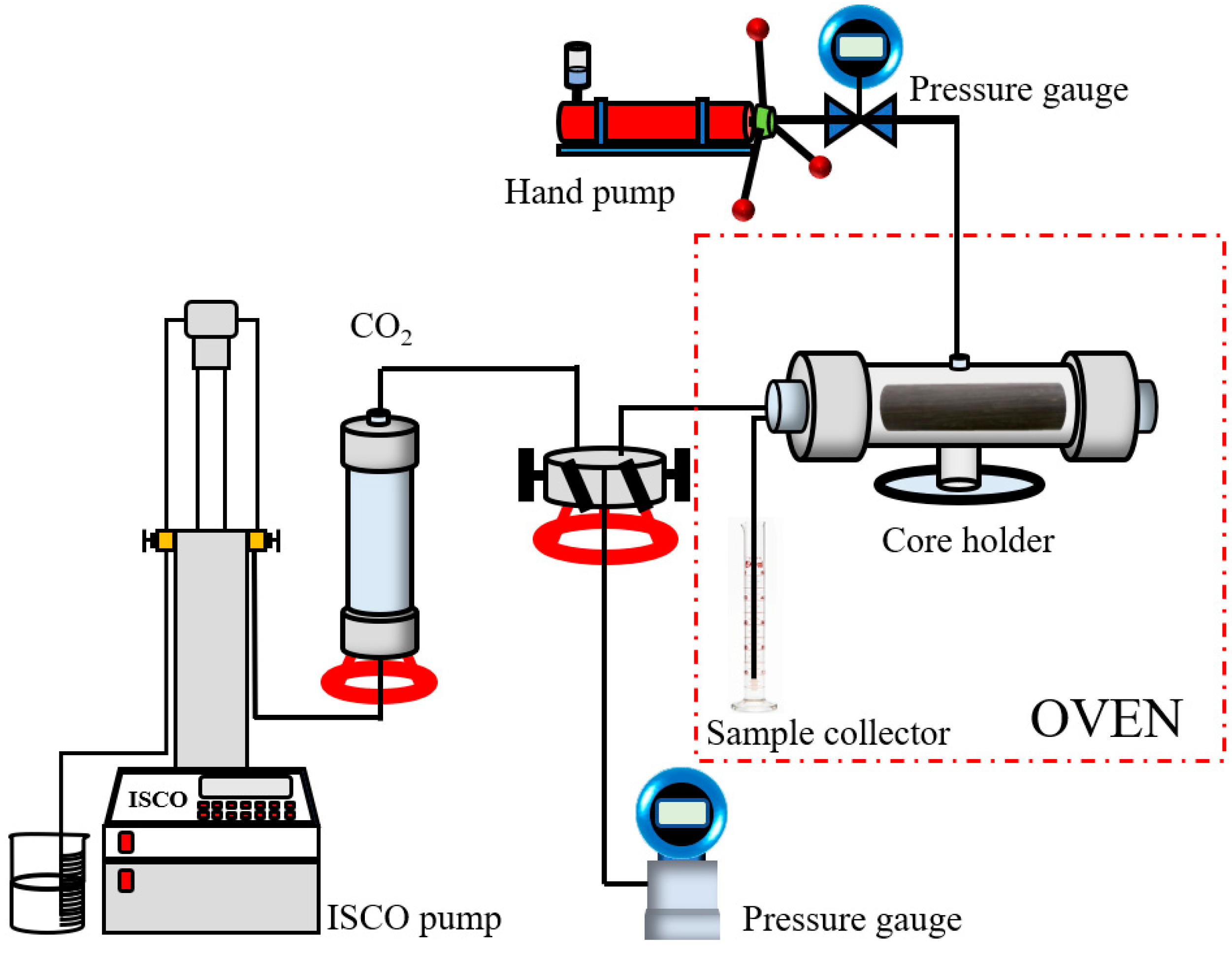
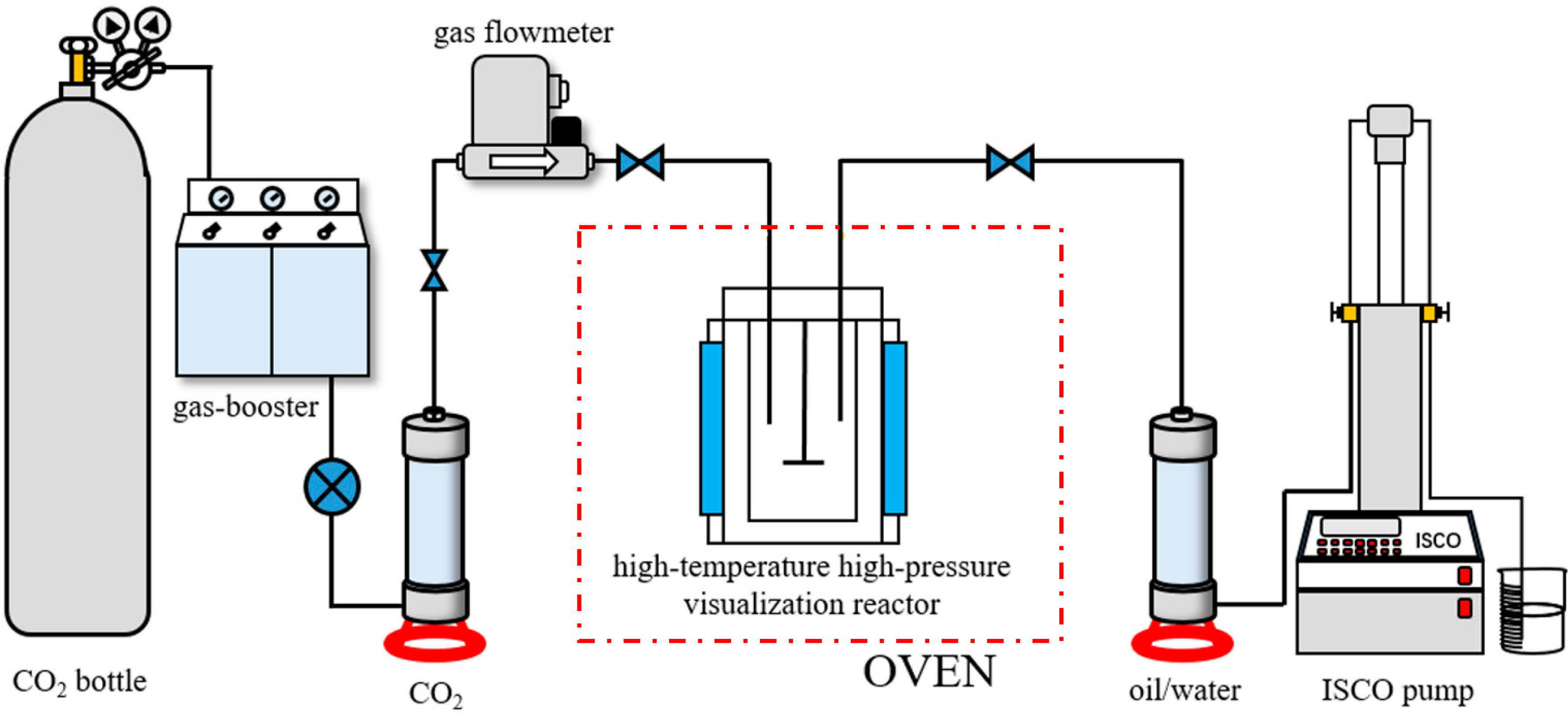
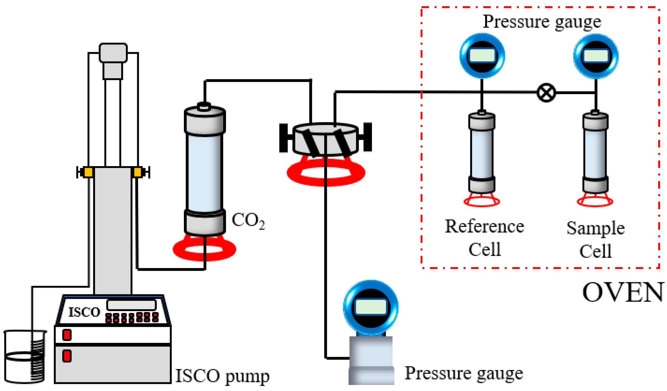
2.2. Experimental Apparatus and Methods

Analysis of porosity and permeability: The porosity and permeability of shale were measured using a high-precision high-pressure porosimeter–permeameter. This apparatus can apply a confining pressure of 0–3000 psi and measure the porosity and permeability within the ranges of 0.1–40.0% and 0.001–10,000 mD, respectively. In this experiment, the specimens were first dried for 24 h and placed in the core holder for the measurement of porosity and permeability at the confining pressure of 3000 psi. The initial porosity and permeability of tested specimens are shown in Table 2.
CO2 huff and puff experiment and CO2 pre-injection experiment: First, the specimens were dried in the oven for 24 h and then placed in an intermediate container for crude oil saturation at a given pressure and temperature, during which the saturated oil volume was recorded. The specimen was then placed in the core holder, and CO2 was continuously injected at a rate of 0.1 mL/min until the pressure reached a pre-specified value, during which the confining pressure was set at the tracking mode and kept at 2 MPa higher than the injection pressure. For conventional CO2 huff and puff, the target injection pressure was set as 20 MPa, and for CO2 pre-injection, 30 MPa. Subsequently, the inlet valve was closed for CO2 soaking for 24 h. Once the soaking was completed, the inlet valve was opened for production, and the oil production was recorded. The experimental apparatus is shown in Figure 2.
Microscopic morphology analysis of shale after CO2 treatment: The Apreo high-performance field-emission scanning electron microscope (FE-SEM), manufactured by Thermo Scientific, was used to capture the microscale morphology variation of the shale surface after CO2 treatment. This FE-SEM is equipped with an energy-dispersive spectroscopy (EDS) system and can deliver resolutions to 1 nm at an accelerating voltage of 1 kV. In this experiment, each sample with a flat and clean surface was prepared via wire-cutting, mechanical polishing and argon ion polishing. The prepared sample was then treated with CO2 and observed in the FE-SEM under the conditions of an accelerating voltage of 10 kV and beam current of 1.6 nA to characterize the microscale pore structure variation of the shale surface attributed to CO2.
Analysis of CO2 solubility: A high-temperature high-pressure visualization reactor for PVT analysis was used to measure the CO2 solubility via the PVT method. First, a given amount of gas was injected into the visualization reactor, and the equilibrium temperature and pressure (T1 and P1) of gas inside the reactor were recorded after the readings of temperature and pressure became stable. Then, a fixed volume of liquid was injected into the visualization reactor via the intermediate container. The temperature and pressure (T2 and P2) inside the reactor were recorded after the re-balancing between gas and liquid in the reactor. Finally, the solubility of the injected gas in the injected liquid was calculated using the equation of state for gas. The experimental apparatus is shown in Figure 3.
CO2 adsorption in shale: First, each shale sample was ground into micron-scale powder. The sample powder was then placed in the sample cell, where it was vacuumed for 24 h at a given temperature. Subsequently, the reference cell was pressurized to the specified pressure using CO2 and sealed, after which CO2 was injected into the sample cell. The pressure readings of both the reference and sample cells were recorded continuously until they reached equilibrium. The adsorbed CO2 in the shale was estimated according to the equilibrium pressure. The experimental apparatus is shown in Figure 4.

3. Results

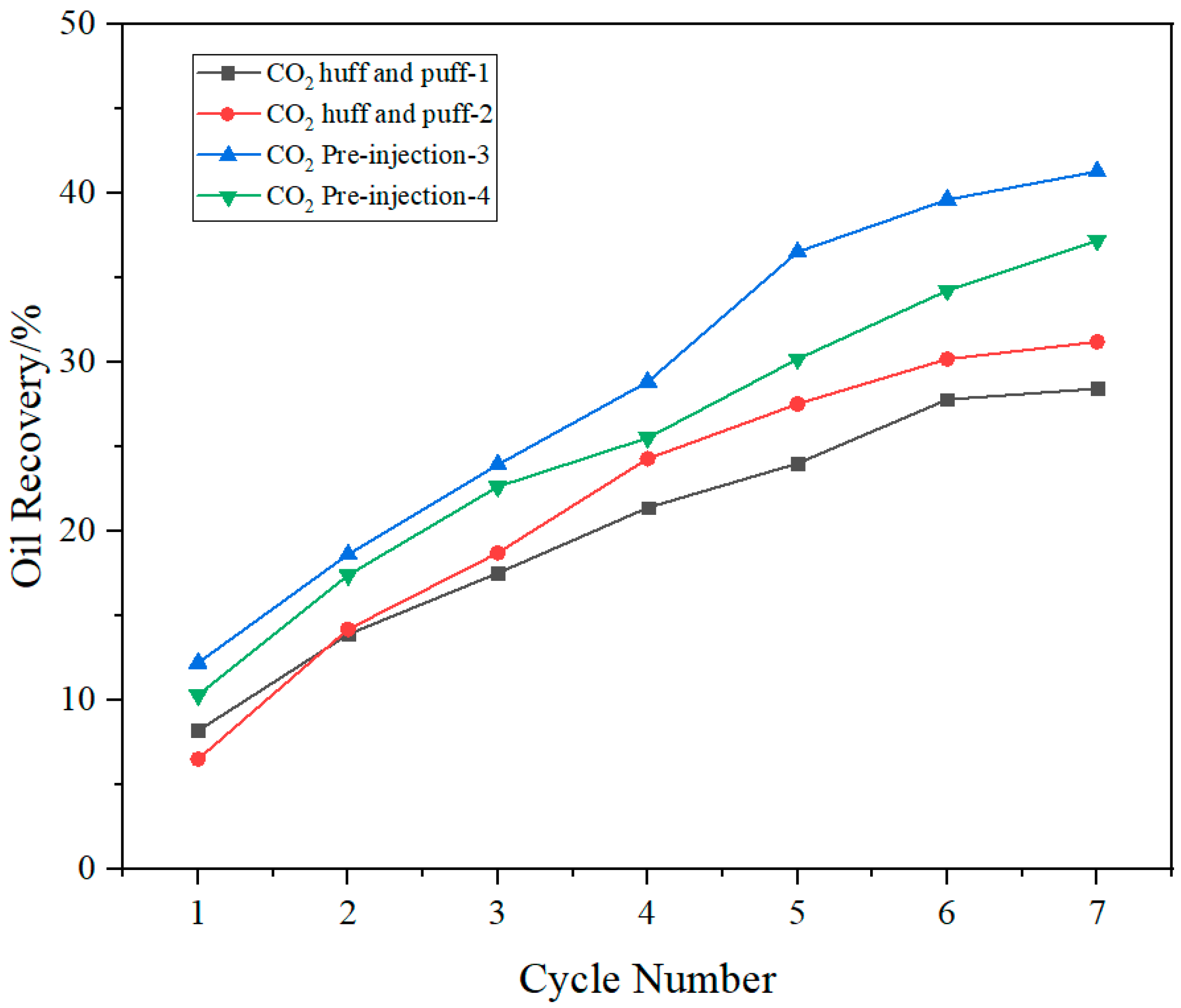
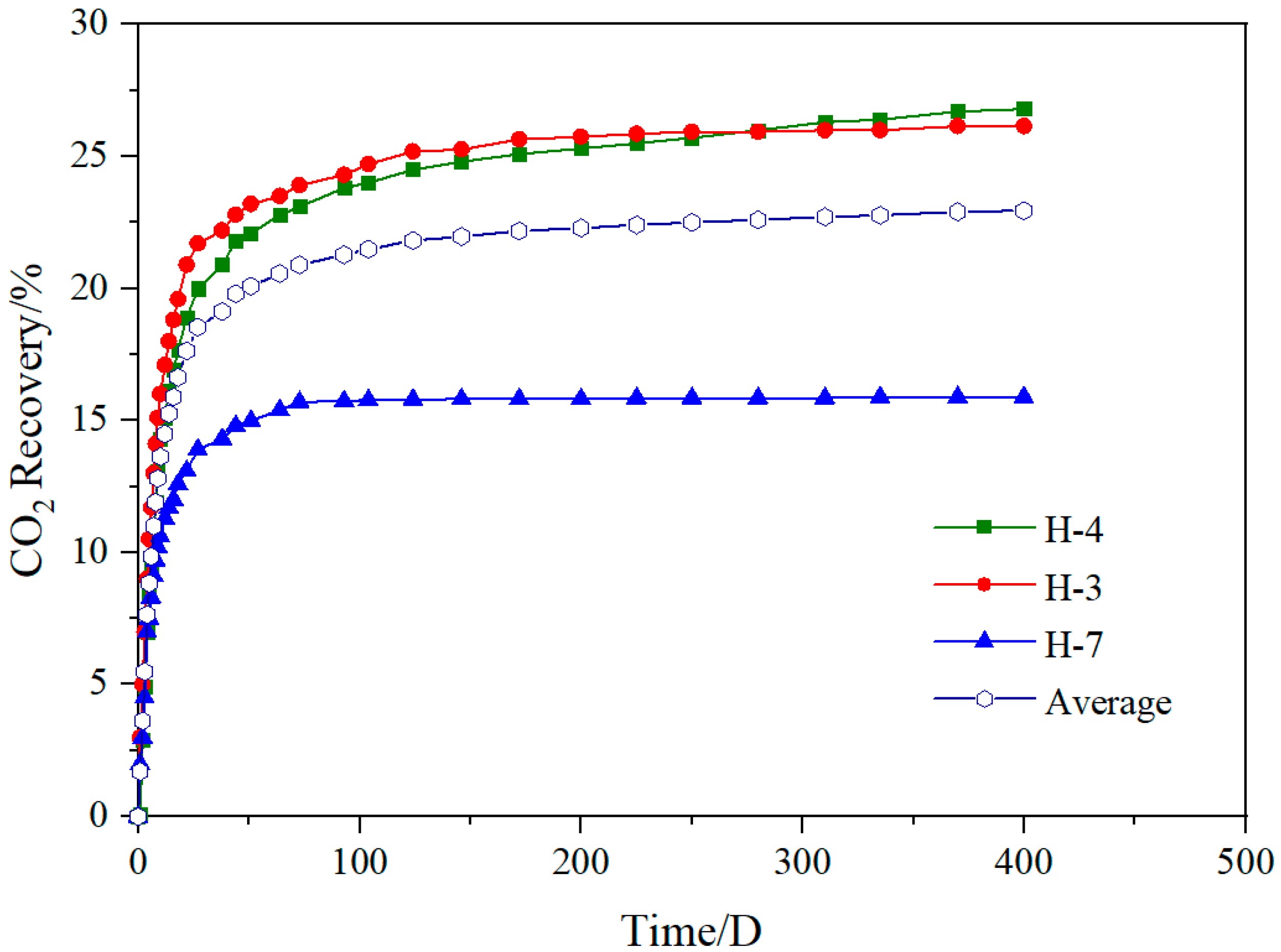
3.1. EOR Performance Analysis of CO2 Pre-Injection

The EOR performances of conventional huff and puff and pre-injection of CO2 were compared via laboratory experiments. The four groups of experiments were all carried out at 90 °C. The soaking pressure for conventional CO2 huff and puff was 20 MPa, while that for CO2 pre-injection was 30 MPa. The oil recovery for seven injection cycles is shown in Figure 5.
Clearly, CO2 pre-injection resulted in considerable growth in oil recovery. This was because the formation pressure after high-pressure, high-rate injection of CO2 during fracturing was much higher than that after conventional CO2 huff and puff. During injection with high pressures and high pump rates, CO2 had stronger diffusion and could enter the smaller nanoscale reservoir space to extract oil and improve the oil recovery.
In addition, previous research states that the MMP between the Qingshankou Formation crude oil and CO2 is about 27.45 MPa [31]. Hence, the miscibility of CO2 with the formation of crude oil cannot be achieved during the soaking phase of conventional CO2 huff and puff. In contrast, it can be achieved during CO2 pre-injection to enhance crude oil mobility and recovery. Also, the increased pressure leads to more EOR-effective injection–production cycles. Compared with conventional CO2 huff and puff that presents a notably reduced increment of oil recovery after six cycles, the CO2 pre-injection managed to deliver considerable growth in oil recovery even after seven cycles.
After mechanical and argon ion polishing, the shale sample surface was seen to have a flat tight matrix with only some small primary pores (1–5 μm in diameter). The pore structure of the shale surface was greatly modified by the CO2, as shown in Figure 6. The primary pores of shale were considerably expanded via dissolution, with pore diameters growing from 1–5 μm to 5–25 μm. Meanwhile, large-area dissolution occurred in zones enriched with minerals that react with CO2, such as albite, potassium feldspar and calcite, which left large dissolution pores in the shale surface. The possible reactions between CO2 and shale that occurred on the shale surface are shown in Equations (1)–(5). These incremental dissolution pores improved the fluid flow capacity of the shale and provided new channels for oil migration. For CO2 pre-injection, the higher injection pressure and rate effectively expanded the swept volume of CO2. This meant a larger stimulated volume with enhanced pore structures and, consequently, higher oil recovery.
2NaAlSi3O8 + 2CO2 + 3H2O = 2Na+ + 2HCO3 + 4SiO2 + Al2Si2O5(OH)4
2KAlSi3O8 + 2H+ + 9H2O = 2K+ + 4H4SiO4 + Al2Si2O5(OH)4
CaCO3 + H+ = Ca2+ + HCO3
CaMg(CO3)2 + 2H+ = Ca2+ + Mg2+ + 2HCO3
[Fe/Mg]5Al2Si3O10(OH)8 + 5CaCO3 + 5CO2 = 5Ca[Fe/Mg](CO3)2 + Al2Si2O5(OH)4 + SiO2 + 2H2O
The photos of shale core specimens before and after CO2 pre-injection are shown in Figure 7. Multiple highly developed horizontal fractures occurred in the shale specimen, which were all gradually generated with the increasing injection cycles; the fractures became exceedingly notable after four injection-production cycles. Such induced fractures expanded the contact area between the CO2 and shale, which effectively enlarged the affected zone of CO2 and enhanced the oil recovery.
The performed physical simulation experiment using shale cores demonstrated the advantages of CO2 pre-injection for EOR. In the case of the conventional CO2 huff and puff, the average oil recovery was 29.84% after seven cycles, while that of CO2 pre-injection reached 39.27%, which was a relative growth of 31.6%. At higher pressure, CO2 was able to penetrate deeper into the cores, create induced fractures to expand its contact with the shale and deliver miscible mixing with oil to improve the oil mobility, all of which jointly enhanced the oil recovery.

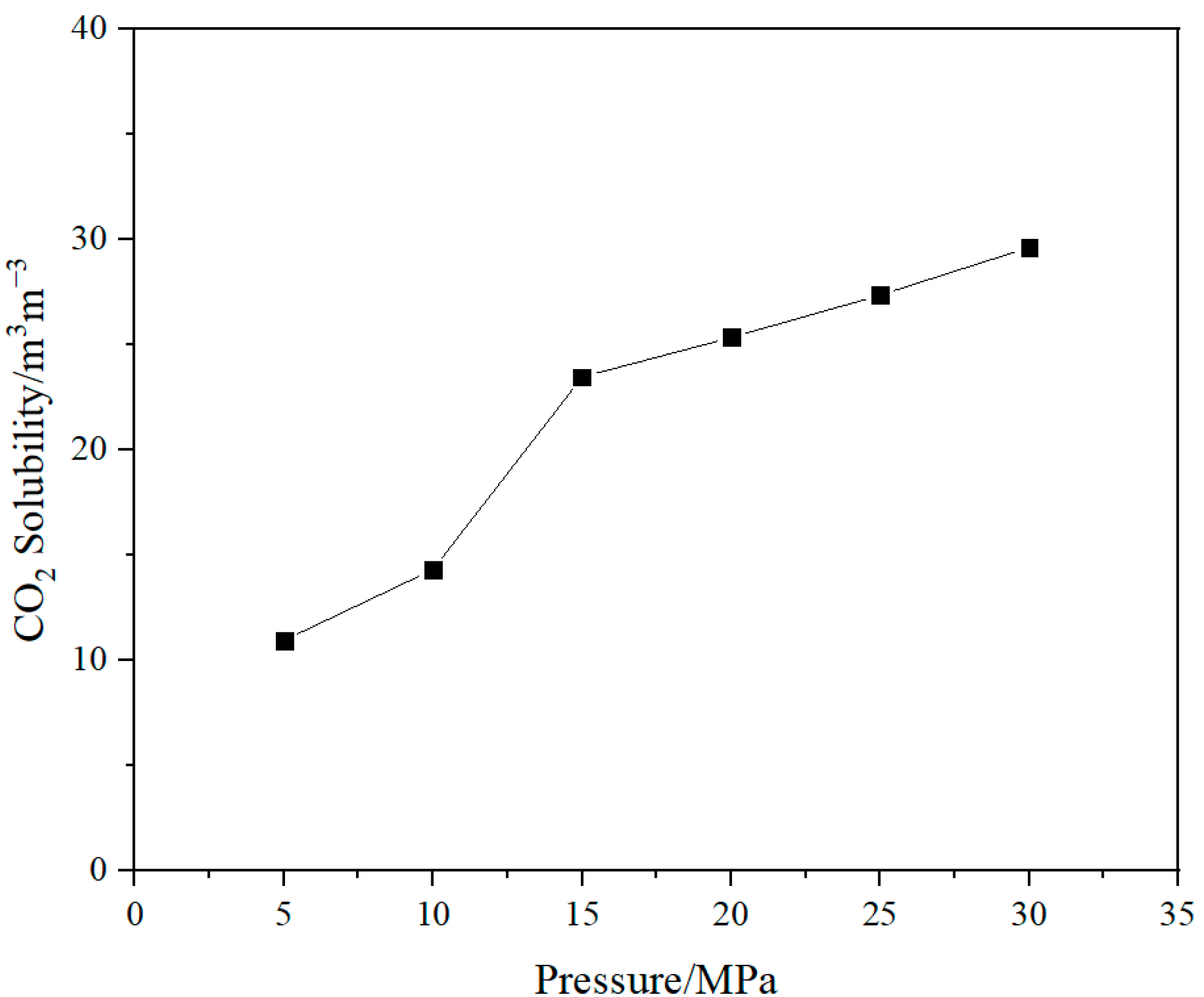
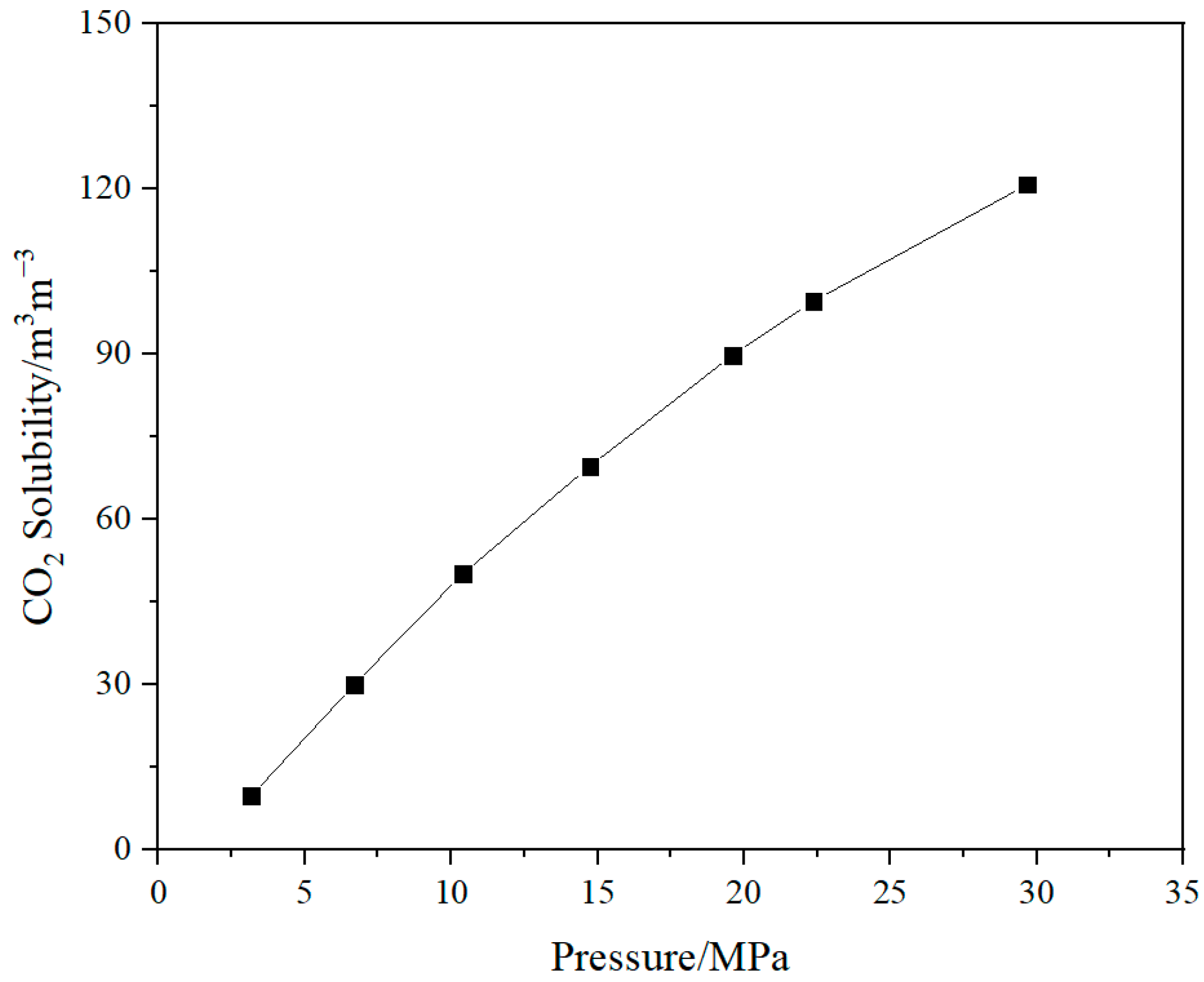
3.2. Analysis of CO2 Solubility in Formation Fluids of Shale Oil Reservoirs during Pre-Injection

The CO2 solubility in the formation fluids was experimentally measured at 90 °C with different pressures to characterize the effects of pressure on CO2 solubility in the formation water. The phase equilibrium data in the PVT reactor were recorded and used to calculate CO2 solubility, as shown in Figure 8. Clearly, at the formation temperature, the CO2 solubility in the formation water grew with the increasing pressure, though this growth slowed down gradually. The solubility at the formation temperature presented greater variations in cases of lower pressure, and an inflection point occurs around 15 MPa, which represented the start of the slowing down of the solubility growth.
Also, the variation in CO2 solubility with formation water salinity was analyzed at the formation temperature and pressure (Figure 9). At a given temperature and pressure, the CO2 solubility declined with the increasing water salinity. This is explained below: CO2 generally exists in solvation shells of water, and ions alter the CO2 solubility by changing the properties of water (the solvent), such as the hydrogen bond and translation and rotation activities. For instance, chloride ions considerably slow down water molecules and strengthen hydrogen bonds, which endows NaCl with the salting-out effect and leads to the degradation of CO2 solubility.
The effects of pressure on CO2 solubility in crude oil were investigated. The corresponding experiments were performed at 90 °C and different pressure, during which the phase equilibrium data of the PVT reactor were recorded to compute the CO2 solubility (Figure 10). At the formation temperature, the solution gas–oil ratio of CO2 in oil increased with the increasing pressure, while the growth amplitudes gradually reduced. This was because the pressurization reduced the oil volume and increases the oil density, and the narrower gaps between oil molecules were unfavorable for the CO2 solution.
To sum up, with the increasing formation pressure, CO2 solubility grew in the formation fluids. The CO2 solubility in crude oil is about 90 m3/m3 in the case of conventional CO2 huff and puff (20 MPa). Due to the tightness of shale reservoirs, the oil recovery factor is typically below 10%, which means a tremendous volume of CO2 can be stored in such reservoirs by dissolving it into formation fluids. As stated above, the injection pressure and rate of CO2 pre-injection were far higher than those of conventional CO2 huff and puff. Moreover, more extensive and more effective contact between CO2 and formation fluids was expected at the higher injection pressure (30 MPa and above). These jointly increased the dissolved CO2, and thus, improved the storage performance of CO2.

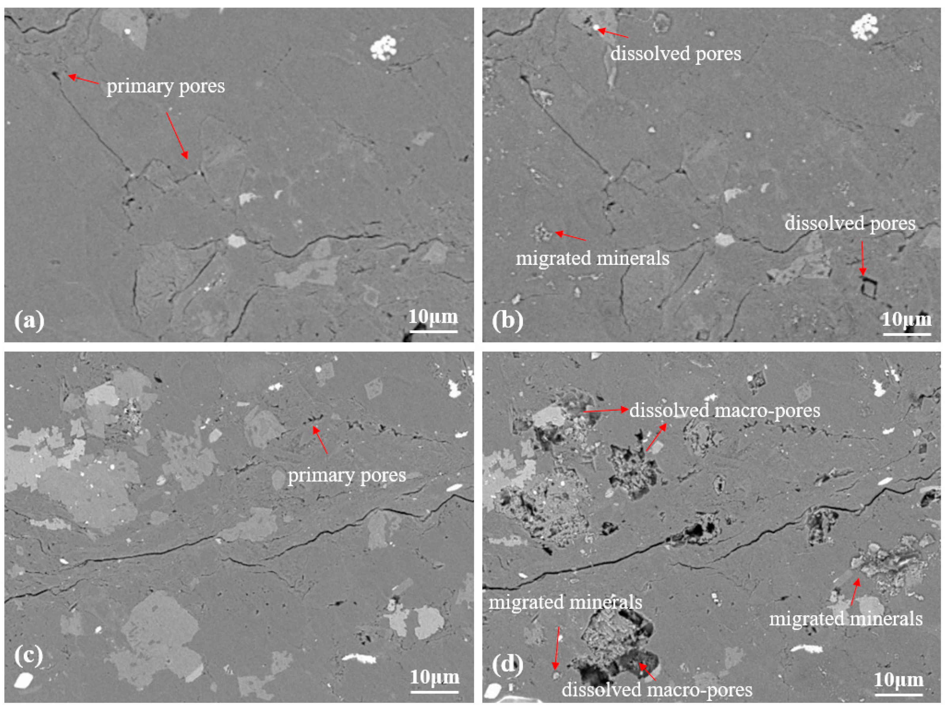
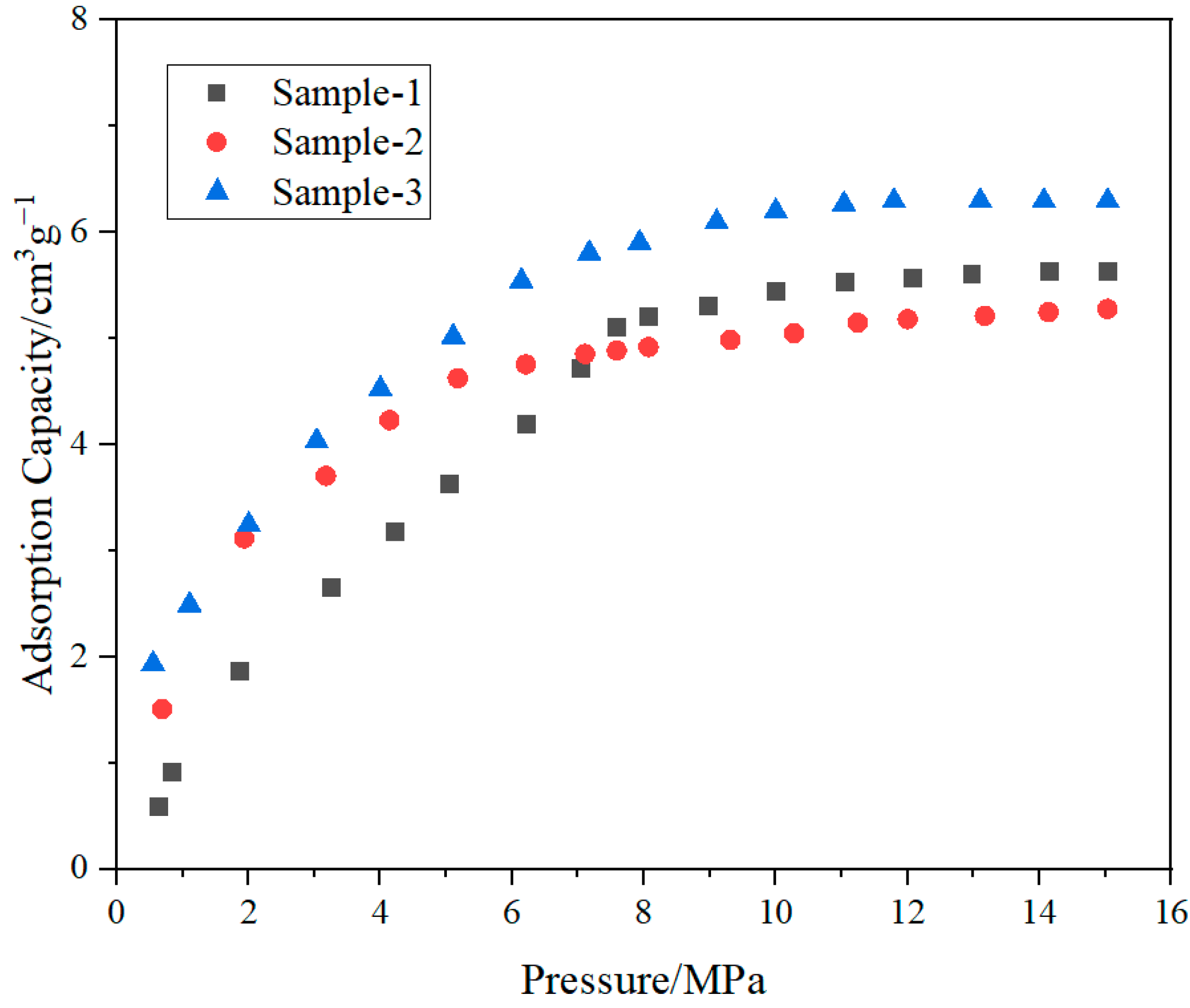
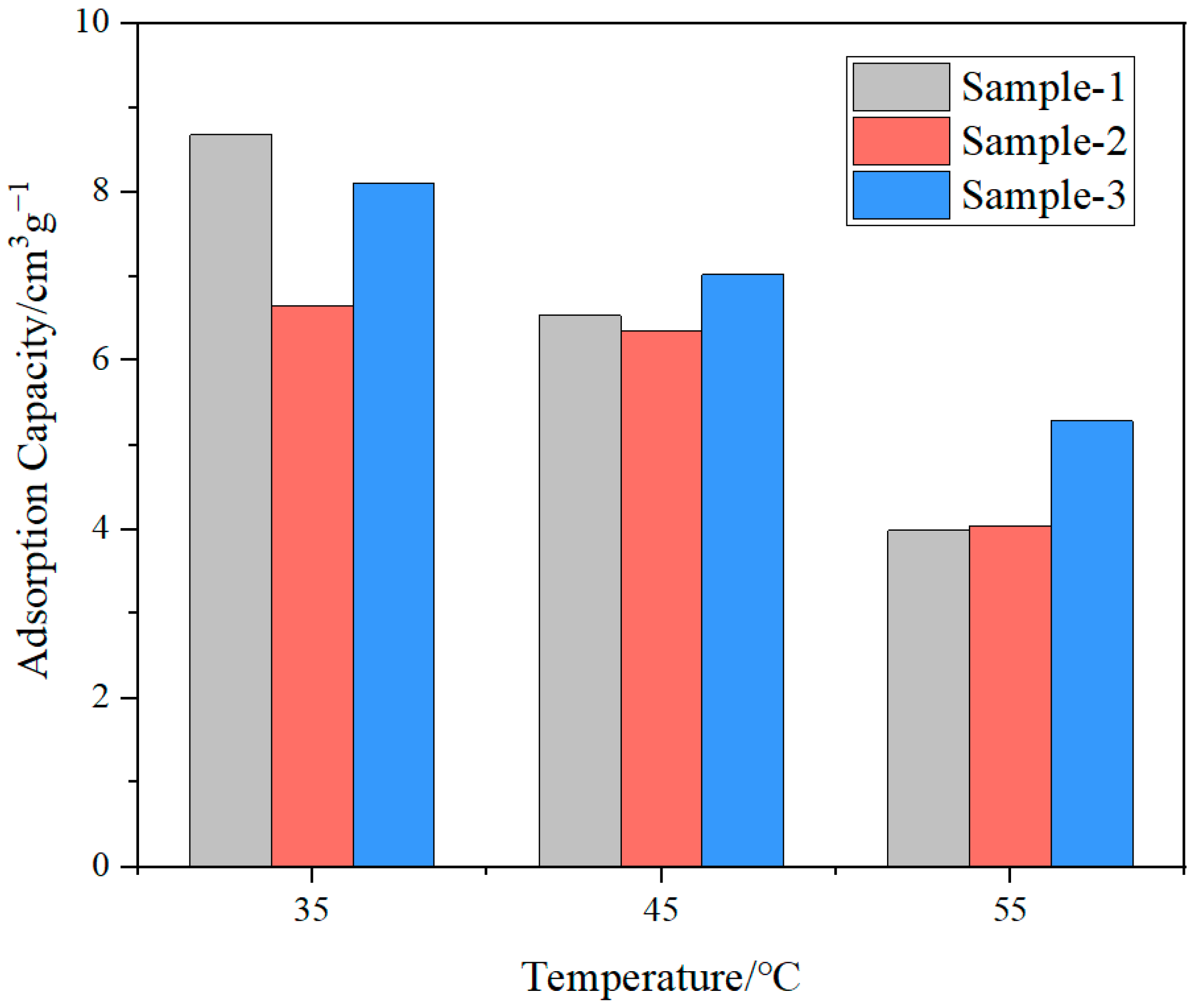
3.3. Analysis of CO2 Adsorption in Shale Oil Reservoirs during Pre-Injection

The adsorption isotherms of CO2 in shale at different pressures were analyzed to characterize the effects of pressure on the adsorbed CO2 volume in shale (Figure 11). With the growing formation pressure, more CO2 molecules were adsorbed onto the shale surface. It should be noted the adsorption growth was much faster at medium–low pressure, while the adsorbed volume gradually became stable at a higher pressure and presented no notable further growth. For CO2 pre-injection during fracturing, CO2 was injected at high pressure and high pump rates, after which the formation pressure was considerably higher than the resultant formation pressure of conventional CO2 huff and puff. It was this higher formation pressure that led to the growth in CO2 adsorbed onto the shale surface and improved the CO2 geological storage performance.
In the case of CO2 pre-injection, the formation temperature was considerably reduced, as a massive volume of liquid CO2 was injected into formations at high pressures and pump rates during fracturing. This phenomenon cannot be overemphasized, as previous research demonstrated that temperature has great effects on the physical gas adsorption capacity of shale. In other words, the adsorbed quantity of gas changes with temperature. Given this, the CO2 adsorption isotherms in shale at different temperatures were measured to characterize the effects of temperature on CO2 adsorption (Figure 12). The adsorbed CO2 reduced with elevated temperature. Higher pressure led to easier desorption and harder adsorption of gas in shale. Accordingly, the CO2 adsorption in shale could be effectively enhanced by the sufficient cooling of formations due to CO2 pre-injection, which further improved the CO2 storage performance.

3.4. Numerical Simulation of CO2 Storage by Pre-Injection

To further validate the CO2 storage performance of CO2 pre-injection in shale oil reservoirs, the numerical simulation was performed for the Qingshankou Formation shale oil reservoir in the Songliao Basin. Specifically, block-wide geological modeling was done for the H block, in which fractures were simulated via localized mesh refinement—the properties of the near-wellbore refined meshes, such as permeability and flow conductivity, were modified to resemble fractures. The constant half-length of the main fracture was 175 m, and that of the branch fracture was 25 m. The spacing of the branch fracture was 10 m, and the main fracture permeability was set to 100 mD, as per the convergence performance of computation. Such mesh refinement was performed for three treatment wells, namely, H-4, H-3 and H-7. The presented simulation covered an area of 4.45 km2 and involved 46,852 meshes. All oil producers and water injectors within the study area were incorporated, and the oil producers were operated at a constant bottomhole pressure.
The simulated variations of CO2 recovery percentage with time of the three wells are shown in Figure 13. The ultimate CO2 storage ratios of wells H-4, H-3 and H-7 were 83.87%, 71.57% and 73.77%, respectively, with an average of 76.46%, which represents excellent storage performance. In addition, the produced CO2 could be collected at the wellhead and re-injected during the next treatments after a simple separation.
It was demonstrated that CO2 pre-injection featured higher injection pressure and pump rates, which enhanced the reservoir rock penetration and pore diffusion of CO2. Under such circumstances, the swept zone of CO2 was greatly expanded, and CO2 could enter micro-nano pores beyond the reach of conventional CO2 huff and puff. After soaking, such CO2 was trapped in the pores and formation fluids of shale reservoirs due to the interfacial tension, dissolution and adsorption, which produced effective CO2 geological storage.

4. Discussion

Unconventional oil and gas reservoirs, unlike conventional ones, sequestrate CO2 mainly via four mechanisms: the storage of free CO2 in microfractures and micro-nano pores of rocks, the CO2 adsorption onto surfaces of minerals and organic matter, the CO2 solution in formation fluids and the CO2 mineralization precipitation. The contributions of these four mechanisms to CO2 storage change considerably, as CO2 constantly migrates in shale (via flow and diffusion) and repeatedly contacts the shale surface, and so does the main occurrence of CO2 in shale.
In CO2 pre-injection, the complex fracture network, which is derived from fracturing, provides more microfractures and macropores for CO2 accommodation and increases the stored free-state CO2. Meanwhile, the high injection pressure pushes CO2 toward the unstimulated shale matrix far from the well, which increases the contributions of the adsorption and solution storage mechanisms. In the subsequent soaking and production, CO2 interacts with the shale matrix and formation fluids, during which it dissolves into formation fluids and adsorbs onto the surfaces of the shale matrix and organic matter. On the one hand, owing to the extremely low recovery factor of shale oil (in most cases, 4–8%), plenty of crude oil remains in shale reservoirs, even in the late stage of development. On the other hand, a good deal of CO2 can be adsorbed onto the surfaces of the shale matrix and organic matter due to the extremely intensive adsorption between CO2 and these materials. Therefore, CO2 pre-injection fracturing can greatly enhance shale oil recovery and, in the meantime, achieve effective geological storage of CO2.
The field pilot program showed after fracturing with CO2 pre-injection, the oil well cumulatively produced oil over 1000 days, with a cumulative oil production of about 11,000 tons and the CO2 storage ratio of this stage surpassing 80%. However, CO2 pre-injection is associated with a series of challenges, such as the crude oil emulsion, pipeline corrosion and the collection of produced CO2. Furthermore, the injection of a large amount of CO2 depends on a mature CO2 pipeline network. All of these may cause extra costs of operation and maintenance [37,38]. Despite these issues needing to be solved, CO2 pre-injection is an effective reservoir stimulation method for the high-efficiency green development of shale oil.

5. Conclusions

This research involved a systematic experimental investigation of the EOR and CO2 geological storage of high-pressure CO2 injection in shale oil reservoirs. Moreover, numerical simulation was carried out to comprehensively analyze the advantages of CO2 pre-injection concerning CO2 storage in shale oil reservoirs. The following conclusions were drawn:
(1)
After seven cycles of conventional CO2 huff and puff, the average oil recovery was 29.84%, while that of CO2 pre-injection was 39.27%, showing a relative growth of 31.6%. At higher injection pressures and pump rates, CO2 could diffuse deeper into the cores, create induced fractures to expand its contact area with the shale and mix with crude oil at the miscible state, all of which jointly led to considerable enhancement of shale oil recovery.
(2)
With increasing pressure, the CO2 solubility grew considerably in both oil and water and so did the quantity of the CO2 molecules adsorbed onto the shale. With the high injection pressure and rate of CO2 pre-injection, more extensive and more effective contact between the CO2 and formation fluids was expected, and this improved the CO2 storage performance.
(3)
Numerical simulation validated the effectiveness of CO2 pre-injection, regarding CO2 geological storage. The simulation results showed that CO2 could flow further into the reservoirs (leading to a larger swept zone) and enter micro-nano pores that were beyond the reach of the conventional CO2 huff and puff. Excellent storage performance was seen in the production stage, as the average storage ratio of CO2 reached 76.46%. CO2 pre-injection has tremendous potential for the geological storage of CO2.

Author Contributions

Conceptualization, Y.L. and J.T.; methodology, J.T.; investigation, A.Z. and C.Z.; writing—original draft preparation, A.Z.; writing—review and editing, A.Z. and Y.L.; visualization, C.Z.; supervision, Y.L. and J.T.; project administration, Y.L.; funding acquisition, Y.L. All authors have read and agreed to the published version of the manuscript.

Funding

This research was funded by the National Key Research and Development Program of China (2022YFC2105401) and China Mining Press Global Risk Survey Market Data Integration (HT202306L0118).

Data Availability Statement

The data presented in this study are available on request from the corresponding author.

Conflicts of Interest

The authors declare no conflict of interest.

References

  1. Masson-Delmotte, A.; Zhai, P.; Pörtner, H.; Roberts, D.; Skea, J.; Shukla, P.; Pirani, A.; Moufouma-Okia, W.; Péan, C.; Pidcock, R.; et al. (Eds.) Global Warming of 1.5 °C; IPCC (Intergovernmental Panel on Climate Change): Geneva, Switzerland, 2018. [Google Scholar]
  2. Li, L.; Zhao, N.; Wei, W.; Sun, Y. A review of research progress on CO2 capture, storage, and utilization in Chinese Academy of Sciences. Fuel 2013, 108, 112–130. [Google Scholar] [CrossRef]
  3. Mccloskey, S.; Anderson, P.; Mirzaei, M. Reservoir characterization and comparison of seismicity-monitoring methods at West Seminole for CO2 utilization and storage. AAPG Bull. 2022, 106, 1899–1920. [Google Scholar] [CrossRef]
  4. Hou, L.; Yu, Z.; Luo, X.; Wu, S. Self-sealing of caprocks during CO2 geological sequestration. Energy 2022, 252, 124064. [Google Scholar] [CrossRef]
  5. Raza, A.; Rezaee, R.; Gholami, R.; Bing, C.; Nagarajan, R.; Hamid, M. A screening criterion for selection of suitable CO2 storage sites. J. Nat. Gas Sci. Eng. 2016, 28, 317–327. [Google Scholar] [CrossRef] [Green Version]
  6. Zhang, L.; Ezekiel, J.; Li, D.; Pei, J.; Ren, S. Potential assessment of CO2 injection for heat mining and geological storage in geothermal reservoirs of China. Appl. Energy 2014, 122, 237–246. [Google Scholar] [CrossRef]
  7. Rathnaweera, T.; Ranjith, P.; Perera, M. Experimental investigation of geochemical and mineralogical effects of CO2 sequestration on flow characteristics of reservoir rock in deep saline aquifers. Sci. Rep. 2016, 6, 19362. [Google Scholar] [CrossRef] [PubMed] [Green Version]
  8. Hosseininoosheri, P.; Hosseini, S.; Nuñez-López, V.; Lake, L. Impact of field development strategies on CO2 trapping mechanisms in a CO2-EOR field: A case study in the permian basin (SACROC unit). Int. J. Greenh. Gas Control 2018, 72, 92–104. [Google Scholar] [CrossRef] [Green Version]
  9. Isah, A.; Arif, M.; Hassan, A.; Iglauer, S. A systematic review of Anhydrite-Bearing Reservoirs: EOR Perspective, CO2-Geo-storage and future research. Fuel 2022, 320, 123942. [Google Scholar] [CrossRef]
  10. Zhou, X.; Li, X.; Shen, D.; Shi, L.; Zhang, Z.; Sun, X.; Liang, Q. CO2 huff-n-puff process to enhance heavy oil recovery and CO2 storage: An integration study. Energy 2022, 239, 122003. [Google Scholar] [CrossRef]
  11. Song, Z.; Song, Y.; Li, Y.; Bai, B.; Hou, J. A critical review of CO2 enhanced oil recovery in tight oil reservoirs of North America and China. Fuel 2020, 276, 118006. [Google Scholar] [CrossRef]
  12. Eide, Ø.; Fernø, M.; Alcorn, Z.; Graue, A. Visualization of carbon dioxide enhanced oil recovery by diffusion in fractured chalk. SPE J. 2016, 21, 112–120. [Google Scholar] [CrossRef]
  13. Middleton, R.; Viswanathan, H.; Currier, R.; Rajan, G. CO2 as a fracturing fluid: Potential for commercial-scale shale gas production and CO2 sequestration. Energy Procedia 2014, 63, 7780–7784. [Google Scholar] [CrossRef]
  14. Alam, M.; Hjuler, M.; Christensen, H.; Fabricius, I. Petrophysical and rock-mechanics effects of CO2 injection for enhanced oil recovery: Experimental study on chalk from South Arne Field, North Sea. J. Pet. Sci. Eng. 2014, 122, 468–487. [Google Scholar] [CrossRef]
  15. Iddphonce, R.; Wang, J.; Zhao, L. Review of CO2 injection techniques for enhanced shale gas recovery: Prospect and challenges. J. Nat. Gas Sci. Eng. 2020, 77, 103240. [Google Scholar] [CrossRef]
  16. Bikkina, P.; Wan, J.; Kim, Y.; Kneafsey, T.; Tokunaga, T. Influence of wettability and permeability heterogeneity on miscible CO2 flooding efficiency. Fuel 2016, 166, 219–226. [Google Scholar] [CrossRef] [Green Version]
  17. Fakher, S.; Imqam, A. Application of carbon dioxide injection in shale oil reservoirs for increasing oil recovery and carbon dioxide storage. Fuel 2020, 265, 116944. [Google Scholar] [CrossRef]
  18. Shi, J.; Shen, G.; Zhao, H.; Sun, N.; Song, X.; Guo, Y.; Wei, W.; Sun, Y. Porosity at the interface of organic matter and mineral components contribute significantly to gas adsorption on shales. J. CO2 Util. 2018, 28, 73–82. [Google Scholar] [CrossRef]
  19. Rani, S.; Padmanabhan, E.; Prusty, B. Review of gas adsorption in shales for enhanced methane recovery and CO2 storage. J. Pet. Sci. Eng. 2019, 175, 634–643. [Google Scholar] [CrossRef]
  20. Myshakin, E.; Singh, H.; Sanguinito, S.; Bromhal, G.; Goodman, A. Numerical estimations of storage efficiency for the prospective CO2 storage resource of shales. Int. J. Greenh. Gas Control 2018, 76, 24–31. [Google Scholar] [CrossRef]
  21. Jia, B.; Tsau, J.; Barati, R. A review of the current progress of CO2 injection EOR and carbon storage in shale oil reservoirs. Fuel 2019, 236, 404–427. [Google Scholar] [CrossRef]
  22. Azenkeng, A.; Mibeck, B.; Kurz, B.; Gorecki, C.; Myshakin, E.; Goodman, A.; Azzolina, N.; Eylands, K.; Butler, S.; Sanguinito, S. An image-based equation for estimating the prospective CO2 storage resource of organic-rich shale formations. Int. J. Greenh. Gas Control 2020, 98, 103038. [Google Scholar] [CrossRef]
  23. Pankaj, P.; Mukisa, H.; Solovyeva, I.; Xue, H. Boosting oil recovery in naturally fractured shale using CO2 huff-n-puff. In Proceedings of the SPE Argentina Exploration and Production of Unconventional Resources Symposium, Neuquen, Argentina, 14–16 August 2018. [Google Scholar]
  24. Wei, B.; Zhang, X.; Liu, J.; Xu, X.; Pu, W.; Bai, M. Adsorptive behaviors of supercritical CO2 in tight porous media and triggered chemical reactions with rock minerals during CO2-EOR and-sequestration. Chem. Eng. J. 2020, 381, 122577. [Google Scholar] [CrossRef]
  25. Chen, C.; Gu, M. Investigation of cyclic CO2 huff-and-puff recovery in shale oil reservoirs using reservoir simulation and sensitivity analysis. Fuel 2017, 188, 102–111. [Google Scholar] [CrossRef]
  26. Li, Z.; Gu, Y. Soaking effect on miscible CO2 flooding in a tight sandstone formation. Fuel 2014, 134, 659–668. [Google Scholar] [CrossRef]
  27. Zhao, W.; Hu, S.; Hou, L.; Yang, T.; Li, X.; Guo, B.; Yang, Z. Types and resource potential of continental shale oil in China and its boundary with tight oil. Petrol. Explor. Dev. 2020, 47, 1–11. [Google Scholar] [CrossRef]
  28. Zou, C.; Yang, Z.; Cui, J.; Zhu, R.; Hou, L.; Tao, S.; Yuan, X.; Wu, S.; Lin, S.; Wang, L.; et al. Formation mechanism, geological characteristics and development strategy of nonmarine shale oil in China. Petrol. Explor. Dev. 2013, 40, 14–26. [Google Scholar] [CrossRef]
  29. Yang, Z.; Zou, C. “Exploring petroleum inside source kitchen”: Connotation and prospects of source rock oil and gas. Petrol. Explor. Dev. 2019, 46, 173–184. [Google Scholar] [CrossRef]
  30. Hu, Y.; Hao, M.; Chen, G.; Sun, R.; Li, S. Technologies and practice of CO2 flooding and sequestration in China. Petrol. Explor. Dev. 2019, 46, 716–727. [Google Scholar] [CrossRef]
  31. Tao, J.; Meng, S.; Jin, X.; Xu, J.; Yang, Q.; Wang, X.; Liu, H.; Peng, B. Stimulation and sequestration mechanism of CO2 waterless fracturing for continental tight oil reservoirs. ACS Omega 2021, 6, 20758–20767. [Google Scholar] [CrossRef]
  32. Seo, Y.; Kim, D.; Koh, D.; Lee, J.; Lee, H. Soaking process for the enhanced methane recovery of gas hydrates via CO2/N2 gas injection. Energy Fuels 2015, 29, 8143–8150. [Google Scholar] [CrossRef]
  33. Lu, J.; Nicot, J.; Mickler, P.; Ribeiro, L.; Darvari, R. Alteration of bakken reservoir rock during CO2-based fracturing-an autoclave reaction experiment. J. Unconv. Oil Gas Resour. 2016, 14, 72–85. [Google Scholar] [CrossRef]
  34. Liu, F.; Lu, P.; Griffith, C.; Hedges, S.; Soong, Y.; Hellevang, H.; Zhu, C. CO2-brine-caprock interaction: Reactivity experiments on eau claire shale and a review of relevant literature. Int. J. Greenh. Gas Control 2012, 7, 153–167. [Google Scholar] [CrossRef] [Green Version]
  35. Li, G.; Zhu, R. Progress, challenges and key issues in the unconventional oil and gas development of CNPC. China Petrol. Explor. 2020, 25, 1–13. [Google Scholar]
  36. Liu, B.; Shi, J.; Fu, X.; Lyu, Y.; Sun, X.; Gong, L.; Bai, Y. Petrological characteristics and shale oil enrichment of lacustrine fine-grained sedimentary system: A case study of organic-rich shale in first member of Cretaceous Qingshankou Formation in Gulong Sag, Songliao Basin, NE China. Petrol. Explor. Dev. 2018, 45, 828–837. [Google Scholar] [CrossRef]
  37. Marinina, O.; Nechitailo, A.; Stroykov, G.; Tsvetkova, A.; Reshneva, E.; Turovskaya, L. Technical and economic assessment of energy efficiency of electrification of hydrocarbon production facilities in underdeveloped areas. Sustainability 2023, 15, 9614. [Google Scholar] [CrossRef]
  38. Fetisov, V.; Ilyushin, Y.; Vasiliev, G.; Leonovich, I.; Müller, J.; Riazi, M.; Mohammadi, A. Development of the automated temperature control system of the main gas pipeline. Sci. Rep. 2023, 13, 3092. [Google Scholar] [CrossRef]
Figure 1. Photo of the shale core specimens.
Processes 11 02387 g001
Figure 2. Schematic diagram of the EOR physical model simulation apparatus.
Processes 11 02387 g002
Figure 3. Schematic diagram of the high-temperature, high-pressure visualization reactor for PVT analysis.
Processes 11 02387 g003
Figure 4. Schematic diagram of CO2 adsorption experiment.
Processes 11 02387 g004
Figure 5. EOR performance comparison during laboratory experiments.
Processes 11 02387 g005
Figure 6. SEM analysis of shale samples: (a,c) before CO2 treatment and (b,d) after CO2 treatment.
Processes 11 02387 g006
Figure 7. Photos of a shale core before and after CO2 pre-injection.
Processes 11 02387 g007
Figure 8. CO2 solubility in formation water vs. formation pressure.
Processes 11 02387 g008
Figure 9. CO2 solubility in formation water vs. salinity.
Processes 11 02387 g009
Figure 10. CO2 solubility in crude oil vs. formation pressure.
Processes 11 02387 g010
Figure 11. CO2 adsorption in shale vs. formation pressure.
Processes 11 02387 g011
Figure 12. CO2 adsorption in shale vs. formation temperature.
Processes 11 02387 g012
Figure 13. Recovery percentage of CO2 vs. time.
Processes 11 02387 g013
Table 1. Ionic analysis of produced water.
IonsNa+ and K+Ca2+Mg2+ClSO42−HCO3
Concentration (mg/L)232039514503073420
Table 2. Physical properties of shale specimens.
Specimen No.Diameter (cm)Length (cm)Porosity (%)Permeability (mD)
1—Huff and puff2.515.015.490.0314
2—Huff and puff2.515.005.170.0224
3—Pre-injection2.505.015.810.0392
4—Pre-injection2.515.024.960.0271
Disclaimer/Publisher’s Note: The statements, opinions and data contained in all publications are solely those of the individual author(s) and contributor(s) and not of MDPI and/or the editor(s). MDPI and/or the editor(s) disclaim responsibility for any injury to people or property resulting from any ideas, methods, instructions or products referred to in the content.

