Review

Nanofluids as a Waste Heat Recovery Medium: A Critical Review and Guidelines for Future Research and Use

IN+ Center for Innovation, Technology and Policy Research, Instituto Superior Técnico, Universidade de Lisboa, Avenida Rovisco Pais, 1049-001 Lisboa, Portugal
*
Author to whom correspondence should be addressed.
Processes 2023, 11(8), 2443; https://doi.org/10.3390/pr11082443
Submission received: 14 July 2023 / Revised: 8 August 2023 / Accepted: 11 August 2023 / Published: 14 August 2023

Abstract

:
The thermal energy storage and conversion process possesses high energy losses in the form of waste heat. The losses associated with energy conversion achieve almost 90% of the worldwide energy supply, and approximately half of these losses are waste heat. Hence, waste heat recovery approaches intend to recuperate that large amount of wasted heat from chimneys, vehicles, and solar energy systems, among others. The novel class of thermal fluids designated by nanofluids has a high potential to be employed in waste heat recovery. It has already been demonstrated that nanofluids enhance energy recovery efficiency by more than 20%. Also, the use of nanofluids can improve the energy capacity of steelworks systems by around three times. In general, nanofluids can improve efficiency and reduce exergy destruction and carbon emissions in devices like heat exchangers. The current work summarizes the application of nanofluids in waste heat recovery and discusses the involved feasibility factors. Also, the critical survey of more than one hundred scientific papers enabled the overview of the environmental aspects of the nanofluid’s waste heat recovery. Finally, it discusses the main limitations and prospects of the use of nanofluids in waste heat recovery processes.

1. Introduction

This overview attempts to estimate whether nanofluids are suitable for several existing routes for waste heat recovery. Along with the main benefits and drawbacks of the use of nanofluids in this technological area, this work aims to furnish an extensive examination of the preparation and thermophysical properties of nanofluids, including thermal conductivity, specific heat, density, and rheology, among others. The main influencing factors of these properties are also discussed. It also briefly describes the main worldwide sources of waste heat and their representativeness among global waste energy amounts. Nonetheless, the main scope of the review is to evaluate the feasibility of the application of nanofluids and phase-change materials in the various waste heat recovery approaches using equipment like heat exchangers and heat pipes in different technological fields such as HVAC systems, fuel cells, cement industry, and heat engines, among others. There will be addressed diverse research topics on the use of nanofluids in waste heat recovery, like heat transfer enhancement, heat recovery capability, equipment compactness, cost-effectiveness, pressure drop, and environmental concerns, among others. Moreover, it has been demonstrated that around 72% (2016) of worldwide energy consumption is released into the environment as waste heat in the forms of exhaust and effluent losses, like the amount of thermal energy discharged to a refrigerant and other types of losses. Nearly 52% (2016) of energy losses are exhaust and effluent losses that can be recovered, whereas the balance is not practical to retrieve. Also, energy efficiency has been attracting the interest of the research community to explore efficient methodologies to decrease energy demands. Moreover, in recent years, global warming and harsh environmental impacts from fossil fuels led to the implementation of reducing greenhouse gases policies, including the already achieved European Union 20-20-20 goals in 2020 and, especially, the European Union Fit to 55 package, which is a set of proposals to revise and update the European Union legislation to reduce the net greenhouse gas emission by at least 55% by the year 2030. One of the main mechanisms of the mentioned package is the Carbon Border Adjustment Mechanism (CBAM) which deals with imports of products in carbon-intensive industries. The objective of this mechanism is to prevent, along with full compliance with the international trade rules, that the greenhouse gas emissions reduction in the European Union are offset by increasing emissions outside its borders by the relocation of the production to countries where the climate change counter policies are less ambitious than those of the European Union or increased imports of carbon-intensive products. One of the most prominent energy efficiency fields is waste heat recovery because of its cost-effectiveness and strong, helpful features. Waste heat recovery has been deployed to enhance energy efficiency, particularly with fossil fuel systems involved in the aluminum industry [1], ceramic industry [2], and desalination [3], among others. Also, waste heat recovery enables the reduction of fuel demands and inherent environmental impacts such as greenhouse gas and CO2 emissions [4]. The fundamental waste heat recovery routes are the heat-to-heat, heat-to-work, and heat-to-power ones [5]. The heat-to-heat waste heat recovery is a facile and straightforward way of using heat exchangers with considerable recovery efficiency. Nonetheless, its applicability is not the better one since the energy is recovered in the form of heat [6]. The heat-to-work approach deals mainly with mechanical energy and mimics the thermodynamic cycles or heat engines derived from the Carnot cycle like the Rankine cycle [7] and Kalina cycle. Finally, in the heat-to-power mode, the heat is recovered and converted to electrical energy [8]. Such an approach can be carried out by the combined heat and power generation through the connection of commonly used heat engines to an electric generator [9]. Furthermore, another way to follow the heat-to-power route is by thermoelectric generators using thermoelectric material [10] and thermal electrochemical cycles [11]. Nonetheless, it is noteworthy that as the amount of converted energy increases, from the heat-to-heat heat-to-work to heat-to-power, the energy recovery efficiency diminishes, which is caused by the energy losses in every conversion phase [12]. Additionally, heat-to-power waste heat recovery entails low energy conversion efficiency, significative investment cost, and certain backdraws incoming from the use of thermoelectric materials. In this scenario, improved heat transfer fluids like nanofluids have been expanding their scope of application. For instance, apart from waste heat recovery, nanofluids and nanomaterials can also be applied in waste heat recovery conversion, as demonstrated in the experimental works of researchers Mai et al. [13], Straub et al. [14], and Pandya et al. [15]. Nanofluids possess enriched thermophysical properties, given that the incorporation of nanostructures to a base fluid usually enhances the thermal conductivity and specific heat of the resulting thermal fluids, leading to improved heat transfer parameters like the Heat Transfer Coefficient (HTC) [16]. The broad exploration of nanofluids leads to an enhanced energy conversion efficiency and, consequently, diminishes energy consumption for thermal management purposes. Additionally, a very wide range of nanoparticles, including gold, silver, and copper, metallic oxides like magnesium oxide, silica, and alumina, carbon nanotubes, graphene, and graphene oxide has been used in nanofluids for waste heat recovery approaches and processes [17]. Remarkably, the utilization of nanofluids has been extensively increasing in the last few years. Because of their improved features, nanofluids can be applied in a wide range of heat transfer-enhancing processes. Research work on the matter, heat transfer enhancement underlying mechanisms, and different uses of nanofluids are still in their initial phase of knowledge. Being aware of such evidence, this overview intends to address the fundamental advances in waste heat recovery by nanofluids. Consequently, the current work discusses the main preparation methods of nanofluids and their application in the different waste heat recovery routes. It also assesses the fundamental expressions and models to determine the thermophysical properties of nanofluids. This review also addresses the techno-economic feasibility of nanofluids in waste heat recovery processes and associated environmental aspects. The latter is of great importance as the production of the nanoparticles and their addition to the base fluids entails potential environmental toxicity. Moreover, the limitations and further recommended studies are also listed, together with the fundamental conclusions on the subject. Figure 1 summarizes the main waste heat recovery approaches using nanofluids.

2. Waste Heat Sources

Heat is one of the common types of energy used in definitive form in heating and cooling applications or under intermediate form derived from the traditional power generation from fuels. The primary source of heat is the combustion of fuels, which release vast quantities of energy [18]. As an example, the average heat content of natural gas is approximately 8.6 MJ/m3 at normal temperature and pressure [19]. A significant part of industrial applications uses the heat contained in vapor, acting as a heat transfer medium, having high, medium, and low pressure grades of vapor [20]. Nonetheless, the main problem with heat is that it requires a temperature gradient to be transferred from the higher-temperature stream to the lower-temperature stream, leaving waste heat that cannot be further transferred from the heat source to the heat dissipator [21]. The energy losses in different processes are a thermodynamic fact that is rather difficult to avert, given that no thermal process can attain a complete energy efficiency of 100%, and most of the energy losses are released under the form of heat. According to the work of Forman et al. [22], the global waste heat comes from exhausts/effluents (52%), energy services (28%), and other losses (20%). By sectors, and according to the same study, waste heat is mainly produced by the electricity sector (61%), transportation (18%), industrial (9%), residential (7%), and commercial (6%). A work elaborated by authors Vance et al. [23] has shown that in the US industry, around 113.6 TWh of waste heat comes from chimneys, furnaces, steel electric arc furnaces, and the glass industry. Moreover, researchers Cheng et al. [24] showed that high-temperature solid granular material in, for instance, the cement, coke, and steel industries were associated with approximately 160, 700, and 1400 TWh of waste heat in India, the United States, and China, respectively. A significant part of waste heat amount can be linked to energy losses, which account for 45% of conventional power plants, 40% of pumps and fans, and up to 80% of compressors [25]. This clearly shows that waste heat sources are widely spread across different processes to the level that it is hard to find a particular industry without waste heat. The feasibility of waste heat recovery depends mainly on the quality and quantity of waste heat and the state (gas, liquid, or solid) of the waste heat stream [25]. Figure 2 summarizes the fundamental waste heat recovery applications with nanofluids.

3. Nanofluids

3.1. Preparation Methods

Nanofluids can be produced by dispersing nanoparticles in base fluids. A uniform dispersion that mitigates the clustering and sedimentation of the included nanoparticles is paramount. In this direction, these are usually added to nanofluid surfactants to improve their stability over time. Apart from this, the modification of the surface of the dispersed nanoparticles and application of strong force on their clusters can enhance the stability over time of nanofluids. The one-step and two-step methods are the main preparation methodologies to synthesize nanofluids.

3.1.1. One-Step Method

This method averts some stages of the manufacturing and handling of the incorporated nanoparticles, such as drying and dispersion of the nanoparticles and their storage and transportation. For example, the physical vapor deposition technique can produce relatively stable nanofluids in which the evaporation and condensation of the nanoparticles occur in the base fluid. The most advantageous feature of the one-step methodology is the relatively reduced agglomeration and sedimentation of the nanoparticles. The main limitations are the fact that this method is expensive and originates residual reactants left in the final nanofluids.

3.1.2. Two-Step Method

The two-step is the most cost-effective and scalable of nanofluid preparation methods. In this methodology, the nanoparticles are first manufactured through different techniques and, after that, are dispersed into the base fluids. The fundamental associated limitation of this method is the possibility of the aggregation of the included nanoparticles, which can be diminished by the addition of surfactants. A significant part of the research community adopts this method to synthesize nanofluids.

3.2. Thermophysical Properties

3.2.1. Thermal Conductivity

Maxwell [26] proposed a thermal conductivity model for solid–liquid mixtures applicable for spherical-sized nanoparticles and for moderate and low concentrations of nanoparticles expressed by Equation (1):
k n f k b f = k p + 2 k b f + 2 ϕ k p k b f k p + 2 k b f ϕ ( k p k b f )
where Knf is the thermal conductivity of nanofluids, Kp is the thermal conductivity of the nanoparticles, Kbf is the thermal conductivity of the base fluid, and Φ is the volumetric concentration of the nanoparticles. Then, Hamilton–Crosser [27] introduced a model that includes the shape factor, which is a generalization of the Maxwell model and can be expressed by Equation (2):
k n f k b f = k p + n 1 k b f n 1 ϕ k b f k p k p + n 1 k b f + ϕ ( k b f k p )
where n = 3/ψ, n is the empirical shape factor, and ψ the dimensionless sphericity factor, with ψ equal to one for spherical nanoparticles. Furthermore, researchers Pak and Cho [28] proposed Equation (3) for an alumina aqueous nanofluid derived from the classical model:
k n f k b f = 1 + 7.47 ϕ
Accounting to the Brownian motion, researchers Xuan et al. [29] proposed Equation (4):
k n f k b f = k p + 2 k b f 2 k b f k p ϕ k p + 2 k b f + k b f k p ϕ k b f + ρ p ϕ C p n p 2 k b f K B T 3 π r c μ b f
where ρp is the density of the nanoparticles, Cpnp is the specific heat capacity of the nanoparticles, KB is the Boltzmann constant, T is the temperature, rc is the radius of the clusters, and µbf is the dynamic viscosity of the base fluid. The Brownian diffusion is given by K B T 6 π r c μ . The radius of the clusters of the nanoparticles rc can be experimentally determined by Particle Size Distribution (PSD) analysis using, for instance, a laser beam particle size analyzer. The radius of the clusters of the nanoparticles can be plotted as a function of the elapsed time from the sonication process. Finally, researchers Yang et al. [30] introduced a model that included the Brownian convection, and it was developed from the kinetic theory of nanoparticles and can be expressed by Equation (5):
k n f k b f = k p + 2 k b f + 2 k p k b f ϕ k p + 2 k b f 2 k p k b f ϕ k b f + 157.5 ϕ C n f u p 2 τ
where Cnf is the heat capacity of the nanofluid per unit volume, up is the Brownian velocity of the nanoparticles, and τ is the relaxation time.

3.2.2. Specific Heat

The specific heat capacity of a substance is the amount of added/released heat enough to alter the temperature of the substance by one degree. Considering the mixture law, the specific heat of nanofluids is given as a function of the volumetric concentration of the nanoparticles by Equation (6):
C p n f = C p n p ϕ + ( 1 ϕ ) C p b f
where Cpnp is the specific heat of the solid nanoparticles and Cpbf is the specific heat of the base fluid. Moreover, researchers Xuan and Roetzel [31] proposed Equation (7) for the specific heat of nanofluids:
C p n f = ϕ ρ n p · C p n p + ( 1 ϕ ) ρ b f · C p b f ρ n f
where ρnp is the density of the solid nanoparticles, ρbf is the density of the base fluid, and ρnf is the density of the nanofluid, which is given by ρ n f = ρ n p ϕ + ( 1 ϕ ) ρ b f . Authors Zhou et al. [32] demonstrated that Equation (6) provides accurate results only at low concentrations of nanoparticles. For this reason, Equation (7) is widely used for the specific heat of nanofluids at a broad range of concentrations of nanoparticles.

3.2.3. Dynamic Viscosity

In the case where two adjacent fluid layers move relatively to each other, the resistance of the fluid to flow can be determined by viscosity, that is, the ratio of the shear stress to the shear strain rate. Einstein [33] proposed a model for estimating the dynamic viscosity of nanofluids that can be expressed by Equation (8):
μ n f μ b f = 1 + 2.5 ϕ
where µnf is the dynamic viscosity of the nanofluid, and µbf is the dynamic viscosity of the base fluid. Nonetheless, this model was not as accurate as that for volumetric concentrations of the nanoparticles lower than 0.02 vol. Furthermore, Brinkman [34] proposed Equation (9) for the dynamic viscosity of nanofluids at volumetric concentrations of the nanoparticles up to 4% vol.
μ n f μ b f = 1 ( 1 ϕ ) 2.5
Additionally, researchers Abu-Nada [35] and Namburu et al. [36] evaluated the heat transfer enhancement of alumina dispersed in water and alumina dispersed in a mixture of water and ethylene glycol nanofluids and proposed a temperature-dependent model given by Equations (10) and (11) for the dynamic viscosity of nanofluids:
μ n f = 0.155 19.582 T + 0.794 ϕ + 2094.47 T 2 0.192 ϕ 2 8.11 ϕ T 27,463.863 T 3 + 0.127 ϕ 3 + 1.6044 ϕ 2 T + 2.1754 ϕ T 2
l o g μ n f = A e B T
where A = 0.29956 ϕ 3 + 6.7388 ϕ 2 55.44 ϕ 236.11 and B = 6.4745 ϕ 3 + 140.03 ϕ 2 1478.5 ϕ + 20,341 10 6 .
Equation (10) can be used at temperature values between − 35 °C and 50 °C and particle volumetric concentrations of the nanoparticles between 1% vol. and 10% vol. Additionally, researchers Nguyen et al. [37] introduced a model as a function of the temperature and expressed by Equation (12):
μ n f μ b f = 2.1275 0.0215 T + 0.00027 T 2
Finally, authors Wang et al. [38] proposed a model that depends on the concentration of the nanoparticles and can be expressed by Equation (13):
μ n f μ b f = 1 + 7.3 ϕ + 123 ϕ 2  
Additionally, authors Naddaf and Heris [39] investigated the dynamic viscosity of a diesel oil-based nanofluid at temperature values between 5 °C and 100 °C. Authors found that the dynamic viscosity of nanofluids decreased with increasing temperature.

3.2.4. Density

Considering the mixture law, the density of nanofluids is given by Equation (14):
ρ n f = ρ n p ϕ + ( 1 ϕ ) ρ b f

3.3. Thermal Conductivity Influencing Factors

The thermal conductivity of nanofluids is influenced by many factors, such as the nature of the base fluid, the type, size, and shape of the added nanoparticles, and operating temperature, among others. The next sub-sections briefly discuss some of the most commonly reported trends between the thermal conductivity of nanofluids and their main impacting factors.

3.3.1. Base Fluid

The thermal conductivity of nanofluids is closely linked to the thermal conductivity of the base fluid. There is a linear relationship between the two thermal conductivities: the nanofluid exhibits higher thermal conductivity in cases where the base fluid has high thermal conductivity.

3.3.2. Type of Nanoparticles

The type or nature of the incorporated nanoparticles in the base fluids significantly impacts the thermal conductivity of the final nanofluid. The addition of high thermally conductive nanoparticles is usually the common choice since they impart a higher thermal conductivity to the nanofluid. The most stable are the metal oxides due to their chemical and thermal stability and the metallic nanoparticles. Nonetheless, the latter are not as cost-effective as others happen to be.

3.3.3. Concentration of the Nanoparticles

The thermal conductivity of nanofluids normally increases with increasing nanoparticle concentration. Most of the existing effective thermal conductivity models include the concentration of the nanoparticles, and a linear and non-linear correlation between the thermal conductivity and concentration of the nanoparticles was experimentally found by the research community. Researchers Barbés et al. [40] examined copper oxide aqueous nanofluids and reported a linear relationship. Moreover, authors Xie et al. [41] found a nonlinear relationship between thermal conductivity and the fraction of nanoparticles for carbon nanotubes dispersed in glycol nanofluids.

3.3.4. Size of the Nanoparticles

The thermophysical properties of nanofluids, like, for instance, thermal conductivity, are influenced by the size of the incorporated nanoparticles. The thermal conductivity of nanofluids, in most of the published cases, increases with the decreasing size of nanoparticles. If the nanoparticles are small, the Brownian motion becomes dominant, and the randomly wised motion of the nanoparticles in the base fluid increases, and consequently, the thermal conductivity of the nanofluid also increases. Also, the surface-to-volume ratio increases with the decreasing size of the nanoparticles.

3.3.5. Shape of the Nanoparticles

The shape of the added nanoparticles also impacts the thermal conductivity of nanofluids, as demonstrated by Hamilton-Crosser [27]. The influence of the shape of the added nanoparticles was studied by researchers Timofeeva et al. [42]. Authors used alumina nanoparticles dispersed in a mixture of water and ethylene glycol and confirmed that the cylindrical nanoparticles exhibited the highest thermal conductivity. Additionally, it was already found that the brick-shaped nanoparticles had higher thermal conductivity than the nanoplatelets and blade-shaped nanoparticles [43].

3.3.6. Operating Temperature

The thermal conductivity of nanofluids can be directly related to the operating temperature. In this sense, several researchers have found an ameliorated thermal conductivity of nanofluids with increasing working temperature. The thermal conductivity increases with increasing temperature since the Brownian motion of the nanoparticles becomes stronger. Researchers Duangthongsuk and Wongwises [44] investigated a titanium oxide aqueous nanofluid at a temperature range between 15 °C and 30 °C and found that the thermal conductivity increased with augmenting working temperature from 15 °C to 30 °C.

3.3.7. Addition of Surfactants

The surfactants are usually added to nanofluids to improve their stability over time by diminishing the agglomeration of the nanoparticles. Nonetheless, the surfactant may decrease the thermal conductivity of the nanofluid in the stabilization process. Authors Khairul et al. [45] evaluated copper oxide aqueous nanofluids with the addition of the surfactant SDBS and found that the thermal conductivity deteriorated upon the addition of the surfactant. The thermal conductivity decreased with increasing concentration of the surfactant. Hence, the addition of surfactants should be explored carefully at an optimum concentration.

3.4. Nusselt Number

The heat transfer characteristics of a nanofluid are influenced by many factors, including the thermophysical characteristics of the nanoparticles and base fluid, the size and concentration of the nanoparticles, and surfactants, among others. Therefore, the functional form of nanofluids Nusselt can be expressed as follows:
Nu = f (Re, Pr, Knp, Kbf, ϕ, size of the particle, shape of the particle, flow pattern)
where Re is the Reynolds number expressed by u m D ν n f where um is the mean flow velocity of the nanofluid, D is the inner diameter of the tube, and νnf is the kinematic viscosity of the nanofluid. Pr is the Prandtl number given by ν n f α n f , where αnf is the thermal diffusivity of the nanofluid given by k n f ρ n f C p n f , where ρnf is the density of the nanofluid, and Cpnf is the specific heat capacity of the nanofluid.
Moreover, researchers Heris et al. [46] numerically studied an alumina aqueous nanofluid in a triangular-shaped duct and reported that the Nusselt number increased with decreasing nanoparticle size and increasing nanoparticle concentration. Additionally, authors Pak and Cho [28] proposed Equation (15) for alumina and titanium oxide aqueous nanofluids flowing under a turbulent regime:
Nu = 0.021Re0.8Pr0.5, 6.5 ≤ Pr ≤ 12.3 and 104 ≤ Re ≤ 105
Also, authors Xuan and Li [47] examined a copper oxide/water nanofluid in turbulent flow and proposed Equation (16) for the Nusselt number determination:
Nu = 0.0059(1 + 7.6286Φ0.6886Pe0.001)Re0.9238Pr0.4
where Pe is the Peclet number given by u m d n p α n f , where dnp is the average diameter of the nanoparticles.
Authors Maiga et al. [48] proposed Equation (17) for the Nusselt number of an alumina aqueous nanofluid:
Nu = 0.085Re0.71Pr0.35, 6.6 ≤ Pr ≤ 13.9 and 104 ≤ Re ≤ 5 × 10⁵

3.5. Rheological Behavior

The rheological behavior of a fluid can be interpreted by the relationship between the shear stress and the shear rate. The shear stress can be defined as the tangential force per unit area, and the shear rate can be defined as the alteration of the shear strain per unit time. The viscosity of a fluid can be defined as the ratio between the shear stress and shear rate, and it is a measure of the resistance given by the adjacent layers to one another during the fluid flow. The fluid behavior can be categorized as Newtonian and non-Newtonian. The non-Newtonian can be divided in pseudoplastic, Bingham, Bingham plastic, and dilatant. In the cases where a fluid exhibits Newtonian behavior, its viscosity remains constant, whereas its shear stress exhibits a linear relation with the shear rate. In the case where a fluid shows non-Newtonian behavior, the viscosity varies with the shear rate, and the relationship between the shear stress and shear rate exhibits Bingham behavior. Moreover, the rheological behavior of nanofluids directly impacts their pressure drop and brings some useful insights about nanoparticle structuring, which can be very useful in estimating the thermal conductivity of nanofluids. The rheological behavior can be determined with the aid of rheometers. The titanium oxide-water nanofluids usually show shear thinning behavior, and the titanium oxide-ethylene glycol nanofluids present Newtonian behavior even for high shear rates. Additionally, the multi-walled carbon nanotubes (MWCNTs) exhibit both Newtonian and non-Newtonian behaviors, depending on the type of base fluid in which they are dispersed. Also, a shear thinning behavior was reported by MWCNTs dispersed in water, resin, and oil. Nanofluids containing MWCNTs in silicone oil and glycerol have Newtonian behavior for all concentrations and operating temperatures. It should be noted that the MWCNTs nanofluids with high volume fractions exhibit non-Newtonian behavior, whereas they show Newtonian behavior when they possess lower concentrations. The MWCNTs nanofluids usually exhibit shear thinning behavior for low shear rates and sometimes show Newtonian behavior at high shear rates. The silica nanofluids exhibit Newtonian behavior regardless of the base fluid. A large part of the alumina aqueous nanofluids exhibit non-Newtonian behavior, with the exceptions of the alumina-ethylene glycol and alumina polyethylene glycol, which behave as Newtonian fluids. The aqueous nanofluids with micro-sized alumina particles exhibit a shear-thinning behavior. Also, the alumina nanofluids show a transition from shear thinning behavior to shear thickening as the shear rate exceeds a certain critical level, which increases with increasing concentration of nanoparticles. The copper oxide nanofluids exhibit almost a Newtonian behavior, but with the addition of xanthan gum, they show a shear-thinning behavior. In sum, it can be concluded that a significant part of nanofluids with low concentrations of nanoparticles behave as Newtonian fluids, and nanofluids with high concentrations exhibit non-Newtonian behavior. Nanofluids present Newtonian behavior at low shear rates and non-Newtonian behavior at high shear rates. Also, the spherical nanoparticles are more prone to present Newtonian behavior, whereas the tetragonal and tubular ones usually show non-Newtonian behavior. Nanofluids having base fluids with high viscosity, like, for instance, ethylene glycol, are more likely to exhibit Newtonian behavior than those having base fluids with low viscosity, like water. The addition of surfactants increases the viscosity of nanofluids and may alter their flow pattern to dilatants.

4. Heat-to-Heat Waste Heat Recovery with Nanofluids

The diverse approaches using nanofluids to recover thermal energy from different waste heat sources will be presented. Hence, there will be described the main heat-to-heat, heat-to-work, and heat-to-power waste heat recovery routes where the usage of nanofluids takes an active role. Figure 3 summarizes nanofluids characteristics that are very suitable for waste heat recovery processes.

4.1. Waste Heat Recovery Using Heat Exchangers

There are several types of heat exchangers, the most common being the double pipe, shell and tube, helical or coiled, and plate heat exchangers, having diverse configurations for heat transfer performance and efficiency enhancements [49]. The effectiveness of the heat exchangers depends fundamentally on the temperature values and thermophysical features of the hot and cold streams, together with the constitutive material and channel configuration of the heat exchangers [50]. The improved heat transfer across the heat exchange surface in a heat exchanger from waste heat stream to the nanofluid, and within the nanofluid, shows a more dispersed heat transfer across the nanofluid due to the suspended nanoparticles resulting in an overall plasmonic effect. The heat transfer beams showed a primary heat transfer across the surface from the waste heat stream to the nanofluid. Additionally, due to the presence of the nanoparticles, secondary heat transfer beams within the nanofluid itself are generated, hence improving the heat transfer efficiency beyond that of conventional fluids. Researchers Pordanjani et al. [51] reviewed the energy savings inherent to the use of nanofluids in heat exchangers and confirmed substantial energy savings derived from nanofluids, particularly in the laminar regime flow region, and from the use of hybrid nanofluids as compared to their conventional counterparts. The investigation team also emphasized that further studies are still required to address the underlying mechanisms of the agglomeration and sedimentation of the nanoparticles and corrosion within heat exchangers and to optimize the morphology and concentration of the nanoparticles. Also, authors Zamzamian et al. [52] investigated the influence of the temperature and concentration of nanofluids on the convective HTC using alumina/ethylene glycol and copper oxide-ethylene glycol in double-pipe and plate heat exchangers under turbulent flow. The results showed an increase of up to 50% in the HTC, with better results for the copper oxide nanofluids comparatively to the alumina ones and for the plate heat exchanger in comparison to the double-pipe heat exchangers. Moreover, researchers Attalla and Maghrabie [53] studied the heat transfer and fluid flow of alumina aqueous nanofluid flowing in a plate heat exchanger, showing an increase in the HTC and Nusselt number with increasing volumetric concentration of the alumina nanofluid and surface roughness by up to 14% in the heat transfer efficiency, and up to 30% in the Nusselt number. Furthermore, researchers reported a friction factor increase of around 53% at 1.2% vol. compared to up to 67% at 2.6% vol. at different roughness values, demonstrating that the surface roughness was the main influencing parameter of the friction factor over the concentration. Also, authors Leong et al. [54] used a shell and tube heat exchanger for waste heat recovery in biomass heating plants from flue gas through copper–ethylene glycol and copper-water nanofluids. It was found that at 1% wt. the copper–ethylene glycol nanofluid resulted in a nearly 8% enhancement in the heat transfer rate due to an increase of around 17% and 9.5% in the convective and overall HTCs, respectively. Oppositely, only a 4.5% heat transfer increase was confirmed for the copper aqueous nanofluid, together with 11% less coolant pumping energy for the copper–ethylene nanofluid. Similarly, authors Kong et al. [55] examined waste heat recovery from combustion stack gas employing helical coiled heat exchangers and a graphene-aqueous nanofluid. It was verified that there was an up to 25% enhancement in the HTC for a graphene concentration of 0.05% wt. in reference to that attained with water due to the 13.4% increase in thermal conductivity. Authors Ebrahimi et al. [56] performed work on the application of nanofluids as heat transfer fluids in waste heat recovery processes of a steel-making complex. The authors used a plate heat exchanger to recover the heat from the hot process water. At first, researchers conducted a theoretical study to address the thermal performance of aqueous nanofluids of alumina, silica, zinc oxide, and copper oxide. It was confirmed that the alumina nanofluid was the one that performed better and increased the effectiveness of the heat exchanger by up to 4%. After that, the research team conducted experimental work to confirm the theoretical results and found that the effectiveness of the system was indeed improved, but to a somewhat lesser extent than the one estimated by the prior modeling. Finally, researchers made an economic analysis with the net present value method and concluded that the proposed system was economical in terms of global market prices.

4.2. Waste Heat Recovery Using Heat Pipes

The heat pipes are composed of an evaporator, condenser, and adiabatic sections. The evaporator is located at one end of the heat pipe, where the heat is absorbed, and the working fluid is vaporized. The condenser is located at the other end, where the vapor is condensed, and the heat is released. The adiabatic section is located between the evaporator and condenser, where the two phases flow in opposite directions trough the core and wick sections [57]. The heat pipe contains the fluid and vapor phase, where the saturated fluid turns into vapor, and then it is transferred to the condenser section, where it goes back to liquid form. The fluid that has been condensed is converted to vapor again through the wick section using capillary wicking. The different types of heat pipes include the tubular heat pipe, thermosyphon heat pipe, pulsating heat pipe, rotating heat pipe, heat pipe heat exchanger, loop heat pipe, and gravity heat pipe. Diverse types of heat pipes have already been studied for waste heat recovery purposes. For example, the heat pipe heat exchangers were evaluated for waste heat recovery in surgery rooms in hospitals [58] and air conditioning equipment and systems [59], and the two-phases closed thermosyphons were investigated for waste heat recovery in bakeries [60], in buses to recover the heat from the exhaust gas of the engine [61], and in naturally ventilated buildings [62] leading to an improved cooling ability and energy savings [63]. The fundamental characteristics of a heat pipe that determine its suitability for waste heat recovery processes include the ability to provide an enhanced heat transfer through reduced cross-sections without an external power supply at a broad range of operating temperatures. Nanofluids promote the reduction of the heat pipe temperature gradient and decrease the dimensions of the heat pipe as compared to a heat pipe with a traditional thermal fluid flowing under the same conditions. Additionally, nanofluids improve the boiling heat transfer performance and thermal conductivity in the heat pipes. Nanofluids utilized in waste heat recovery via heat pipes are fundamentally single-particle nanofluids, magnetic nanofluids, and hybrid nanofluids.

4.2.1. Pulsating Heat Pipes

There are three types of forces acting on the nanoparticles dispersed in a nanofluid: gravitational, electrical repulsion, and attraction forces. The electrical repulsion force (zeta potential charge) makes the nanofluid stable, whereas the other forces induce instability to the nanofluid because of the formation of larger clusters, resulting in the nanoparticles’ deposition. The application of a magnetic field could aid the stabilization of the nanoparticles with magnetic properties since it can enhance the heat transfer performance and reduce the need for the ultrasonication preparation phase and surfactant incorporation. Furthermore, researchers Goshayeshi et al. [64] evaluated the impact of incorporating 10 nm to 30 nm iron oxide nanoparticles into kerosene in a pulsating heat pipe with and without the application of a magnetic field. The incorporation of iron oxide nanoparticles ameliorated the thermal efficiency of the heat pipe, particularly with the application of the magnetic field. A magnetic aqueous nanofluid having iron oxide nanoparticles was examined flowing in a five-turn glass pulsating heat pipe with and without the application of an external magnetic field [65]. A hybrid alumina-copper oxide nanofluid at 0.1% vol. at various ratios and flowing in a heat pipe was studied [66]. The 1:3 ratio indicated the lowest thermal resistance having a reduction of nearly 44% compared to that obtained with the water itself caused by the wettability and surface roughness enhancements. The hybrid nanofluid of 0.1% wt. silica-copper oxide and 0.1% wt. alumina-copper oxide in water was analyzed flowing in a 4-turn pulsating heat pipe, showing a thermal resistance reduction of 57% and 34% for silica-copper oxide and alumina-copper oxide nanofluids, respectively, with respect to water [67]. Although the thermal conductivity of the alumina-copper oxide nanofluid was higher than that of the silica-copper oxide nanofluid, the thermal resistance was found to be lower using the silica-copper oxide nanofluid that was attributed by authors to the greater dynamic viscosity of the alumina-copper oxide nanofluid, which hindered the fluid transportation through the heat pipe.

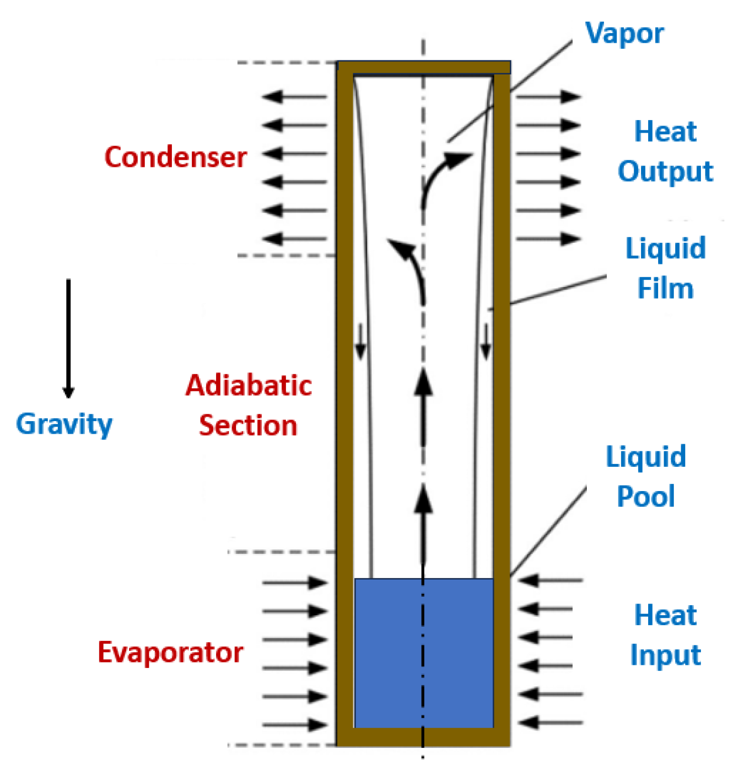
4.2.2. Gravity Heat Pipes

The gravity heat pipes normally exhibit superior thermal performance due to the cyclic phase transformation of the operating fluid. As an important thermal management device for waste heat recovery, the heat transfer capability of the gravity heat pipes improves, the performance and efficiency of waste heat recovery improve, and more wasted heat can be stored more rapidly. In this direction, researchers Qian et al. [68] explored nano-diamond, which has the highest thermal conductivity dispersed in water, to improve the thermal performance of a gravity heat pipe. Additionally, the influences of filling ratio, mass fraction, and heat flux on thermal performance require further studies. Researchers reported that the heat flux had the most significant impact on the thermal performance, followed by the filling ratio and mass fraction. The thermal performance was the best when the optimal parameters of a filling ratio of 20% and a mass fraction of 1% wt. were chosen at a heat flux of 20 × 104 W/m2. The diamond nanofluid heat transfer behavior is studied by observing the flow patterns. The orthogonal experiment and range analysis investigate the influence of the filling ratio, concentration of the diamond nanoparticles, and heat flux on heat transfer capability. The research team also confirmed that the heat transfer capability decreased with increasing filling ratio due to the poor generation of bubbles and vapor flow rate. It will be difficult for the gravity heat pipe with flowing diamond nanofluids at high filling ratios to produce slug flow, and the heat transport capability will decrease. At concentrations of 0.5% wt. and 1% wt., the flow pattern of the nanofluid was dominated by slug flow. At 2% wt., the flow changed to bubble flow. The heat transfer capacity increased with increasing concentration of diamond nanoparticles from 0.5% wt. to 1% wt., then decreased when the concentration reached 2% wt. It was found that the addition of nanoparticles can facilitate the nucleation in the base fluid and enhance the energy transfer inside the diamond nanofluids, which is caused by the leading effect of the nano-diamond heat transfer enhancement effect. The enhanced heat transfer effect of nanoparticles increased with their concentration. When reaching 2% wt., the diamond nanoparticles inhibited the heat transfer in the diamond nanofluid due to the excessively high fluid viscosity, while the equivalent HTC showed a positive relationship with the heat flux and a negative relationship with the filling ratio. When the heat flux increased from 2 × 10⁴ W/m2 to 20 × 104 W/m2, the equivalent HTC rapidly increases from 758 W/(m2 °C) to 2982 W/(m2 °C). And when the filling ratio increased from 20% to 80%, the equivalent HTC dropped by 14–16%. The thermal performance of the gravity heat pipe was enhanced with concentrations of nanoparticles lower than 1% wt. The thermal performance of the gravity heat pipe deteriorated when the mass fraction of the diamond nanofluid increased up to 2% wt. When the filling ratio was 20%, the gravity heat pipe filled with a 1% wt. diamond nanofluid had the best heat transfer capability under 20 × 104 W/m2 heat flux. The equivalent heat transfer coefficient was 3485 W/(m2 °C). Figure 4 illustrates the fundamental sections and principles of a gravity heat exchanger.

4.2.3. Heat Pipes Heat Exchangers

The heat pipe heat exchangers seem like ordinary finned coils, but each successive tube is independent and not connected to the other tubes. Each tube possesses an internal capillary wick material and is evacuated, filled with a compatible fluid according to the range of operating temperatures, and sealed. With the tubes installed horizontally, one half of the heat exchanger will act as an evaporator, and the other half will play the role of a condenser. The high-temperature air stream passes through the evaporator half of the unit, and the low-temperature air stream passes through the condenser half. The high-temperature air stream passes over one half of all the tubes. Since the working fluid is heated and vaporized in the evaporator half, the vapor pressure difference directs the vapor to the condenser end section of the heat tube. In the condenser section, the fluid releases the latent energy of vaporization as it condenses, thus heating the low-temperature air stream. The fluid will return to the evaporator end through the internal wick. Authors Chaudhari et al. [69] studied zinc oxide aqueous nanofluids flowing in a heat pipe heat exchanger and tested them to recapture the heat in low-temperature applications. The thermal performance of the system was inferred at different heat inputs and mass flow rates. The heat input values varied from 25 W to 1500 W, whereas the flow rate Q of air was increased from nearly 0.05 m3/s to 0.24 m3/s. Peak effectiveness of nearly 0.3 was found for a heat input of 1500 W and a flow rate Q of 0.047 m3/s. The authors reported that the HTC increased with increasing source temperature. The performance improvement was caused by better thermal conductivity due to the incorporation of the nanoparticles. It was also verified that the heat pipe heat exchanger with zinc oxide-water nanofluids performed better than the heat pipes charged with conventional thermal fluids. Moreover, recovering the heat from the waste air in residential and commercial buildings it not an easy task to accomplish due to the involved low-temperature range. In this sense, authors Shinde et al. [70] developed a heat pipe heat exchanger for waste air heat recovery processes to provide energy transfer during the simultaneous flow of cold supply and warm drain air. The thermal management equipment was wickless and specially built for waste heat recovery purposes. There were employed boron nitride aqueous nanofluids as thermal fluids. The heat input from the boiler was varied on operating the boiler under different pressures, and the hot and cold air stream flow rate varied from around 0.05 m3/s to 0.26 m3/s. Researchers concluded that the thermal performance of the heat pipe heat exchanger working with the boron nitride aqueous nanofluid increased with increasing temperature. Peak effectiveness of 0.4 was observed for the proposed heat pipe heat exchanger. Also, the results provided by the heat pipe heat exchanger with the boron nitride aqueous nanofluid were superior to those furnished by a heat pipe charged with conventional fluid.

4.3. Pool Boiling Waste Heat Recovery

Heat extraction from wastewater or incinerators is an important and challenging task in the industry’s thermal management systems. Heat recovery boilers are often used in the industry for heat recovery, and their thermal performance is mainly dependent on the Critical Heat Flux (CHF) of the working fluid. Researchers are using nanofluids as a better alternative to conventional base fluids. Also, the pool boiling process is of relevance for the energy sustainability of the wastewater heat recovery and incinerator heat recovery processes. In this sense, authors Thakur et al. [71] explored multi-walled carbon nanotubes and aqueous nanofluids for nucleate pool boiling experiments. It was observed that by using a 0.005 vol% of multi-walled carbon nanotubes dispersed in water, the CHF was enhanced to nearly 2.1 W/m2. Such CHF enhancement was around 62% superior to the CHF required for the water. In addition, at the same concentration of carbon nanotubes, the HTC increased by 30%. Researchers concluded that the enhancement in the CHF was caused by the improved surface wettability of the heat transfer surface by the nanofluid. Accordingly, the deposition of the carbon nanotubes on the surface of the heat transfer surface provoked the CHF enhancement.

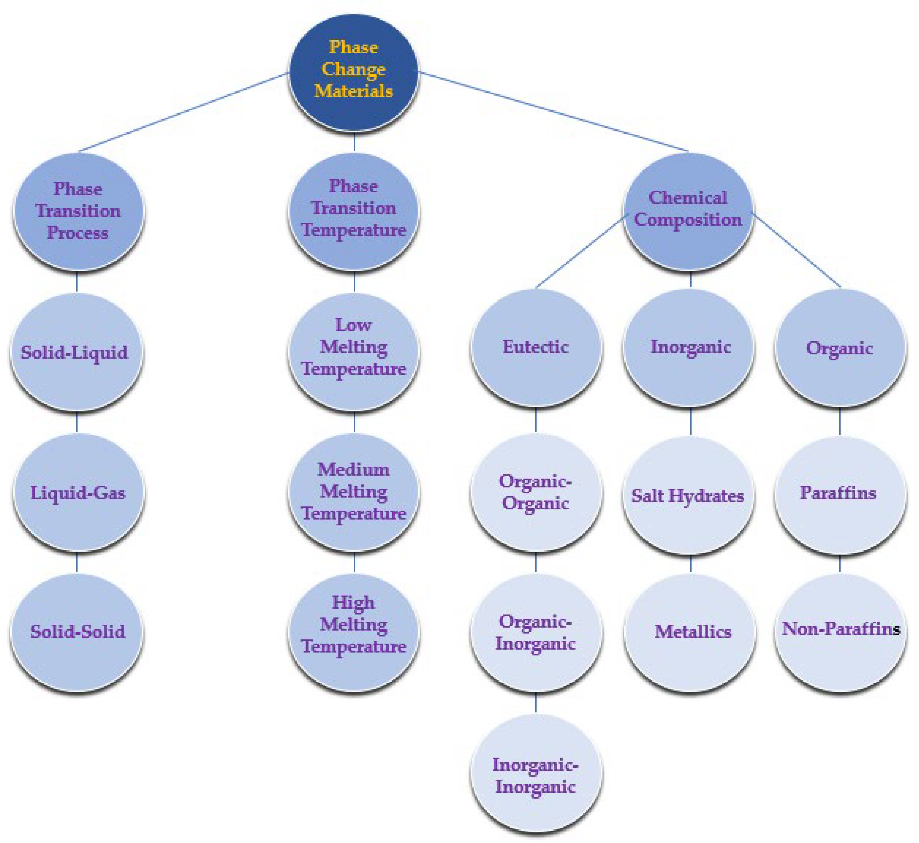
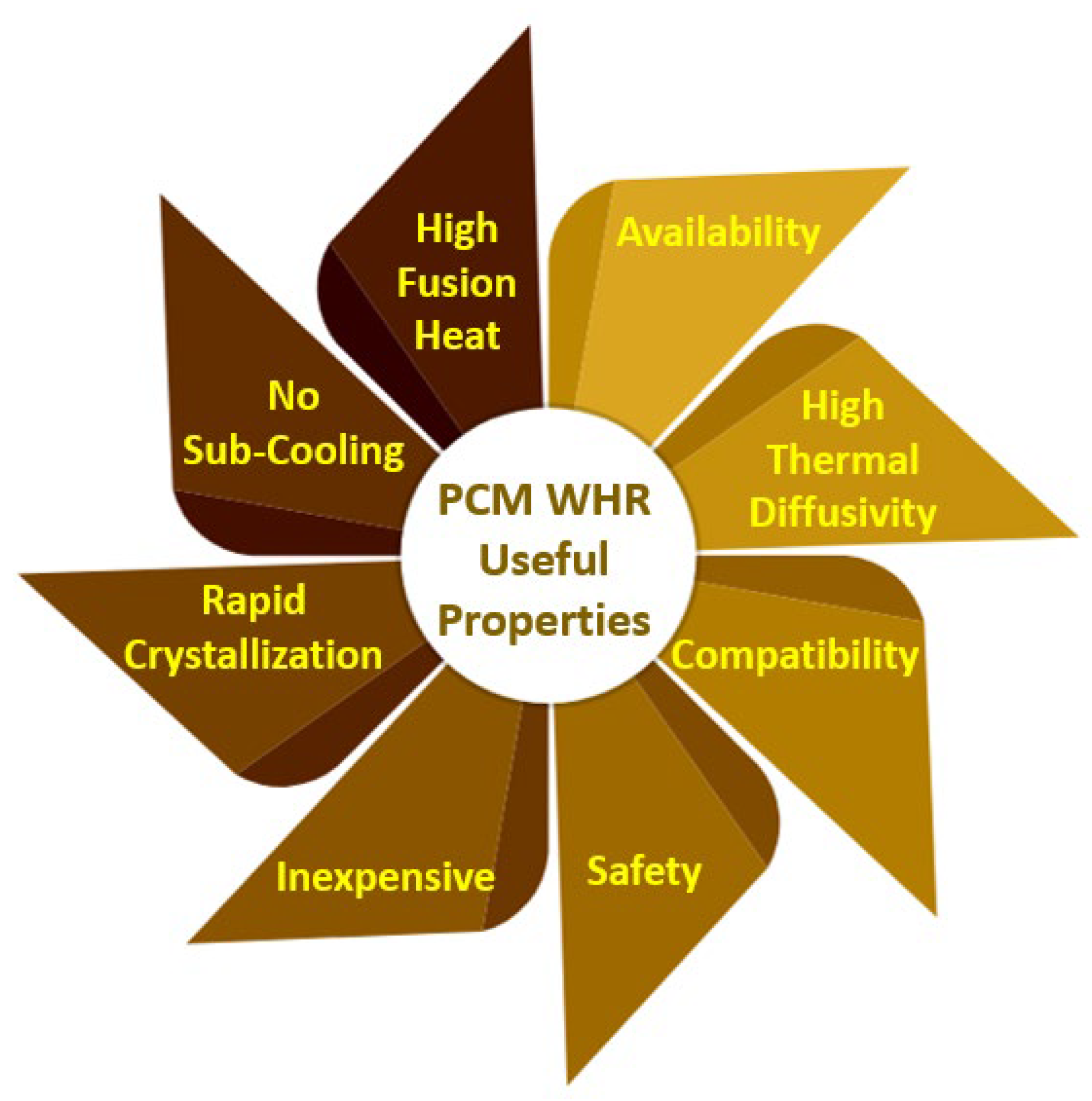
4.4. Waste Heat Recovery Using Phase-Change Materials

The phase-change materials absorb and release energy in the form of latent heat, which is normally dominant when compared to the sensible heat, and low-temperature gradients are the driving force for heat transfer improvement [72]. The phase-change materials can be categorized according to the kind of latent heat being transported into liquid–gas, solid–solid, solid–liquid, and solid–gas. The solid–gas and liquid–gas have higher latent heat and, consequently, heat capacity [73]. Nonetheless, the fundamental concern linked with these two types of phase-change materials is the increased gas volume that evolved during the phase transition, making them unsuitable for large-scale ends. Apart from this, the solid–solid phase change material has a higher phase transition temperature but lower latent heat in comparison with the solid–liquid phase change material that presents a wide phase transition temperature range. The phase-change materials can be divided according to the type of the constitutive material into organic, inorganic, and eutectic mixtures of organic–organic, inorganic–inorganic, and organic–inorganic phase-change materials. The phase-change materials, in general, and the solid–liquid, in specific, are widely utilized in energy storage purposes and have been successfully applied for waste heat recovery [74]. The paraffinic and non-paraffinic organic phase-change materials exhibit the benefits of having self-nucleation capacity, congruent melting, and low corrosivity. The inorganic phase-change materials possess enhanced heat storage capacity or latent heat and thermal conductivity, and of being inexpensive and non-flammable. The inorganic phase-change materials integrate the metals, salt, salt hydrates, and salt mixtures. Figure 5 summarizes the different types of phase-change materials.
The phase-change materials can be in bulk or encapsulated form. In the bulk form, the heat transfer behavior is influenced by the morphology of the container [75]. The phase change material encapsulation is explored to enhance the heat transfer area, decreasing the corrosivity degree of some phase-change materials by avoiding direct contact, controlling the volume alteration during the phase transition, and reducing the backdraws from subcooling [76]. The encapsulation can be done in the form of a core-shell or shape-stabilized configuration in which the phase change material is kept inside a porous material with a capillary effect. One of the fundamental problems associated with phase-change materials is their low temperature and poor thermal conductivity, which needs prolonged periods and greater surface area. As an example, the paraffin-based phase-change materials, which are one of the most used phase-change materials, have excellent availability, cost-effectiveness, superior thermal and chemical stabilities, and suitable melting points between 18 °C and 30 °C and are adequate to be used in a broad range of applications, have only a poor thermal conductivity of 0.2 W/m K [77]. Also, the thermal conductivity of the phase-change materials can be increased by adding high thermally conductive nanoparticles and by the microencapsulation technique [78]. The resulting materials are commonly known as nano-enhanced phase-change materials. There are three types of nanomaterials inorganic nanoparticles, such as metals, metal oxides, and metal nitrides; organic nanoparticles, such as single and multi-walled carbon nanotubes, carbon nanofibers, and graphite, and hybrids, which are a combination of organic, inorganic or both. The organic-based nanoparticles are usually used to decrease the subcooling degree, while inorganic nanoparticles improve thermal conductivity [79]. The use of phase-change materials in waste heat recovery in the cement industry is described in the corresponding dedicated sub-section of the review. Figure 6 summarizes the properties of the phase-change materials with the most interest in waste heat recovery approaches.

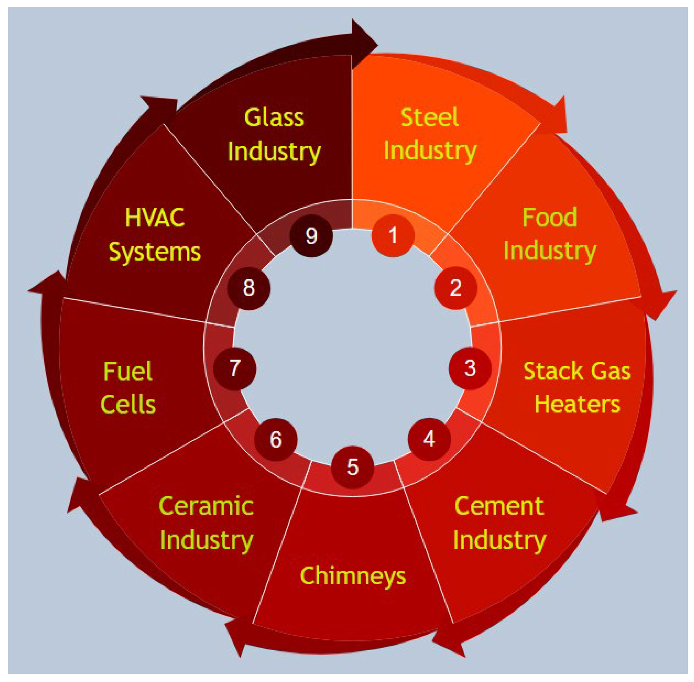
4.5. Main Areas of Actuation of the Heat-to-Heat Waste Heat Recovery

4.5.1. HVAC Systems

Heating, ventilation, and air-conditioning, commonly designated by HVAC systems, usually account for up to 60% of the energy demand in residential buildings. Hence, many heat recovery methods are increasingly adopted to decrease the heating and cooling demands of the HVAC systems through pre-heating or pre-cooling. In energy recovery ventilation, the technological solutions for waste energy recovering are studied. The exploration of air-to-air energy recovery devices and systems in HVAC systems continues to increase. The more demanding outdoor air requirements needed to accomplish the ASHRAE standards regarding the building ventilation for the indoor air acceptable quality entailed appreciably the cooling and heating charges. The augmentation of the outdoor air loads will increase the operating and equipment costs. Such facts had a great interest in energy recovery systems and their economic implications. The new and retrofit energy recovery methodologies can be divided into process-to-process, process-to-comfort, and comfort-to-comfort approaches. In the process-to-process route, the sensible heat is taken from the exhaust stream, and it is transported to the supply one. In a significant part of the process-to-comfort approaches, the recovery of energy involves the capture and transfer of sensible heat only. Waste heat is transferred to makeup or outdoor air streams. This is effective during winter months, but it requires modulation during spring and autumn to prevent overheating of the residential buildings. Usually, no energy recovery is made during summer. Comfort-to-comfort applications differ from other categories in that both sensible and latent heat are often transferred. The heat recovery equipment transports sensible heat from the air stream with a higher temperature to the air stream with a lower temperature and transports the moisture from the air stream with the higher humidity ratio to the air stream with the lower humidity ratio. The devices and systems for energy recovery ventilation have attracted special interest from researchers as the rotating wheels transport moisture and heat. One wide utilization of the two-phase closed thermosyphons is to make them act as gas–gas heat exchangers for heat recovery processes in the HVAC technology. In this sense, researchers Firouzfar et al. [80] experimentally studied a two-phase closed thermosyphon using a silver–methanol nanofluid in an air conditioning system. Researchers reported that the two-closed thermosyphon heat exchanger could save up to 31.5% energy for cooling and up to 100% by reheating the supply air. A two-phase closed thermosyphon using the R407C cooler for cogeneration of residential buildings was evaluated by authors Byrne et al. [81]. The obtained results showed that the thermal performance increased by almost 17% in comparison with that achieved with a standard reversible heat pump. Moreover, authors Jouhara and Merchant [82] examined a nine-finned two-phase closed thermosyphon heat exchanger and predicted its effectiveness. The authors observed that the heat exchanger could provide improved performance in the vertical direction at varying heat inputs from 750 W to 1500 W. The performance of an air-to-air two-phase closed thermosyphon heat exchanger was numerically and experimentally evaluated by researchers Danielewicz et al. [83]. It obtained consistency between the theoretical predictions and experimental results. The heat recovery rate and effectiveness increased with the increasing ratio of the condenser inlet mass flow rate to the evaporator inlet mass flow rate. Moreover, authors Meena et al. [84] experimentally studied a two-phase closed thermosyphon heat exchanger using copper-distilled water nanofluids with a filling ratio of 50% at temperature values between 60 °C and 80 °C. The research team verified that the maximum efficiency occurred at 80 °C, and the thermal effectiveness performance increased compared to that achieved with distilled water only. In air conditioning facilities with high outside air requirements, such as clean room air conditioning systems, considerable energy savings are possible through heat recovery processes using heat pipe heat exchangers. Furthermore, researchers Zhang and Zhang [85] inferred the applicability and energy-saving potential of a dedicated ventilation system combined with a heat pipe heat exchanger to diminish energy consumption under distinct laboratory conditions. The energy savings and efficiency of the heat pipe were determined under diverse outdoor conditions. The numeric simulation and experimental results demonstrated that the energy savings and efficiency of the heat pipe exhibited similar evolutions at different outdoor temperatures and relative humidity values. It was reported that the heat pipe could save up to 60% of energy during the operating air-conditioning period. The total energy consumption of the system decreased from 1.8% to 2.8%. Thus, the results revealed that the developed set-up was very suitable for the thermal management of residential buildings to obtain high energy savings in subtropical climates in which the air-conditioning needs vary a lot. In work conducted by Ahmadzadehtalatapeh [86], it was inferred that the impact of a heat recovery heat pipe heat exchanger on the efficiency of an existing HVAC system of an operating theater. The existing HVAC system, designated by Case 1, was reconfigured by the addition of heat pipe heat exchangers as Case 2 and Case 3, and an adequate configuration in terms of energy saving and air quality was proposed. The TRNSYS simulation software was employed, assuming an operation of 8760 h per year. In view of the obtained results, the authors concluded that the application of heat pipe heat exchangers Case 3 could reduce the energy need of the system, and it was suggested by the authors to be integrated into the HVAC system. Also, it was already demonstrated that the heat pipe heat exchangers integrated systems improved the supply duct and room air quality. In the operating theaters, the exhaust air is always separated from the fresh outdoor air. Hence, the energy recovery potential is quite high. Additionally, the de-humidification capability of the cooling coils can be improved by the pre-cooling effect of the energy recovery equipment. In addition, providing clean indoor air for the operating theaters is of great importance to the designers of the systems. The ASHRAE (American Society of Heating, Refrigerating, and Air-Conditioning Engineers) standard proposes a temperature between 20 °C and 24 °C and from 30% to 60% of relative humidity for the operating theaters. Additionally, the ASHRAE proposes relative humidity values lower than 70% for low-velocity ducts and indoor spaces to avoid fungal creation and growth. Consequently, keeping the supply air relative humidity value lower than 70% is highly recommended. One adequate mode for decreasing the energy consumption of the HVAC systems is to employ heat pipe heat exchangers. Moreover, authors Noie-Baghban and Majideian [58] developed a heat pipe heat exchanger to recover the heat in hospitals and laboratories in which the air should be changed up to 40 times per hour. The characteristic design and heat transfer limitations of single heat pipes for different types of wick and different working fluids have been studied initially by computer simulation. The production of heat pipes that incorporate the washing, insertion of the wick, vacuum production, flowing of the working fluid, and final installation have also been performed. After obtaining the appropriate heat flux, the air-to-air heat pipe heat exchanger was conceived, fabricated, and tested at low-temperature values with methanol as an operating fluid. The obtained results for the absorbed heat by the evaporator section were consistent with the heat transfer rate attained with the numeric simulation. Two streams of inlet fresh air and return air were connected to the heat pipe heat exchanger to evaluate the thermal behavior and efficiency of the heat recovery system. There were adopted the ratios of mass flow rate between the inlet and return air of 1, 1.5, and 2.3 to validate the heat transfer process and temperature alteration of the inlet fresh air. The inlet fresh air temperature from 32 °C to 40 °C was controlled, whist the inlet return air temperature was maintained unchanged at approximately 26 °C. The obtained results demonstrated that the temperature modifications of the fresh and return air increased with increasing inlet temperature of fresh air. The effectiveness and heat transfer for the evaporator and condenser sections were increased to approximately 48% when the inlet fresh air temperature was increased to 40 °C. The impact of the mass flow rate ratio on the efficiency was beneficial for the evaporator section side and detrimental for the condenser section side. The enthalpy ratio between the heat recovery and conventional air mixing was increased to nearly 85% with the increasing temperature of the inlet fresh air.

4.5.2. Cement Industry Waste Heat Recovery

Cement production is one of the most intensive, energy-consuming, and largest carbon-emitting industrial sectors due to the very high-temperature values required to obtain the cement clinker. The cost of energy consumption in the cement industry signifies 20% to 40% of the total production cost. According to the International Energy Agency, energy consumption can still be as high as approximately 0.5 GJ/ton of cement (Canada, 2018). Waste heat sources from the cement plants comprise the exhaust gases from the pre-heater and the ejection of hot air from the cooler of the clinker. In terms of cogeneration power, these waste heat sources, which have various temperature levels, can be employed independently or in combination. The rotary kilns are worldwide explored by various industries to manufacture a wide range of products such as lime, cement, magnesia, alumina, vermiculite, and iron ore pellets. There are many published studies on waste heat recovery processes in the cement sector that incorporate waste heat recovery from flue gases and rotary kiln surfaces. Whereas the former has attracted much interest from the industry, and waste heat recovery plants for flue gases are installed in cement plants, the latter is still not followed because of some practical concerns regarding the kiln operation. The cement plant kiln releases an appreciable heat quantity to the surroundings through its surface. Therefore, the heat can be extracted by developing and implementing a suitable waste heat recovery system over the kiln shell. A model of a rotary kiln explored for the calcination process of dolomite in magnesium manufacturing having a heat exchanger was proposed by authors Karamarkovic et al. [87]. The kiln employed radiant and convective heat loss from the kiln shell surface and avoided excessive heating, did not need air tightness, and was implementable over rotary kilns having a similar distribution of temperature at the surface. The heat losses that occur from the surface of the rotary kilns during the calcination are the main waste heat source in the cement industry. To recuperate this heat, it was used a multi-shell heat exchanger, which formed an annular duct over the zone with a high temperature of the kiln furnace. The phase change material paraffin wax with a melting point of 68 °C was filled between the gap of the two concentric annular steel shells that are thermally insulated from the outside. For comparison analysis, a mild steel heat exchanger model that extracts waste heat from the kiln was studied with and without the tertiary shell containing the phase change material. Also, the outer surface of the heat exchanger was insulated by glass wool, and to facilitate the passage of air between the shells for heat transfer, a variable-speed centrifugal fan was installed. The experimental results showed that the waste heat recovery rate was increased from 3% to 8%, depending on the air-flow rate, using the phase change material. Nonetheless, the model used various thermal, geometrical, and air-flow conditions for the fabrication of cement. It employed the paraffin wax 6499 phase change material in the experimental model, and a comparison was made, and it was concluded that the phase-change materials enhance waste heat recovery. Phase-change materials are often used for thermal energy storage employing the latent heat of a phase change material for storing heat with large energy densities in combination with very small temperature variations and to stabilize the temperature [88]. As in this model, the surface of the kiln releases enough energy through convection and radiation. The phase change material absorbs the heat and releases it when the operating fluid comes in contact with it. The stored energy during a latent storage process can be determined by Q = mL, where m is the mass and L is the latent heat of the phase change material [89]. It was used paraffin wax, which is an organic phase change material in the model, based on the consideration that suitable phase-change materials should possess adequate thermophysical, kinetic, and chemical properties [88]. Paraffin is suitable as heat fusion storage material due to its large temperature range availability. Considering the economic factors involved in these systems, the technical grade paraffins are used as phase-change materials in latent heat storage systems. The main paraffin benefits were its reliability, safety, cost-effectiveness, non-corrosive nature, and chemical stability and inertness at temperature values lower than 500 °C. The paraffin also exhibits melting small volume alterations and possesses low vapor pressure under melt form. Also, it should be stated that a system employing paraffin normally shows an extended freeze–melt cycle [90]. The inclusion of paraffin in the model derived its effectiveness from its superior thermal cycling stability, enabling a very high number of phase changes without changing its characteristics. After choosing the phase change material to be used, the question arises now how the phase change material can be integrated into the system. There are different modes to integrate phase-change materials in heat exchanging systems. Encapsulation, as discussed by authors Sharma et al. [88], is one of the effective modes for exploring phase-change materials. The encapsulation process can be categorized into micro- and macro-encapsulation. The micro-encapsulation involves the introduction of micro-particles to enhance the heat storage capability of the phase-change materials. The authors used the macro-encapsulation technique that involves containment of the phase change material in some cylinder or shaped body to prevent the surrounding environmental contamination. The phase change material was placed between the second and the tertiary shell, and some measures were undertaken to avoid the leakage of the phase change material. The model is considered a heat exchanger, consisting of two concentric annular thermally insulated shells surrounding the rotary kiln and carrying the paraffin wax phase change material. Also, the model determined the convective and radiant heat losses to calculate the heat loss of the bare kiln. It also evaluated the amount of recoverable waste heat from the surface of the kiln shell at a fixed mass-flow rate of the operating fluid and the thermal conductivity. The authors discussed the design, production, and validation of a prototype rotary kiln, together with a heat exchanger. The set-up contained thermally insulated suction pipes connected to the outermost shell, and their other ends were connected to the input of a centrifugal fan to attain diverse flow rates. To further enhance the efficiency of the waste heat recovery system, glass wool was included as an insulating material for the secondary shell, given that it possesses lower thermal conductivity in comparison to mineral wool resulting in enhanced overall efficiency of the system. The prototype was designed to allow the changing of the parameters to infer the thermal performance of diverse possible configurations of the heat exchanger, enabling the comparison between the results with and without using the phase change material. The obtained results showed enhancements between 3% and 8% in heat extraction using phase-change materials. The work combined the usage of waste heat recovery systems and phase-change materials and can be taken as a very suitable option for exploring phase-change materials for industrial purposes in waste heat recovery. Thermodynamic analysis and cogeneration for a cement plant were proposed by researchers Khurana et al. [91] and Madlool et al. [92], who highlighted the capability to recuperate heat losses by convection and radiation in a grate cooler through innovative methods that incorporate waste heat loads to heat the operating fluids of a cogeneration cycle. Moreover, researchers Madlool and Hadi [93] aimed to demonstrate waste heat recovery relevance in the clinker cooling system of the cement industry. Also, unlike the conventional waste heat recovery process, the pipe was inserted within the grate cooler to absorb a heat loss fraction. Base fluids like water, ethylene glycol, and engine oil are conventional heat transfer fluids often used for various purposes within the cement industry. It is easy to recognize the notorious heat transfer enhancement that comes from suspended solid nanoparticles in base fluids. Keeping this in mind, the authors dispersed copper nanoparticles in different base fluids to use the resulting nanofluids in the recovery cycle. Researchers conclude that lower specific heat is directed to higher heat transfer capabilities within the possible base fluids. Also, researchers confirmed that the copper nanoparticles dispersed in engine oil showed the best energy-saving, emission-reducing, and cost-saving behavior. Oppositely, the copper nanoparticles dispersed in water were the option with the lowest savings of energy and overall cost and toxic emission reduction. Figure 7 presents a schematic representation of a waste heat recovery process in a cement production plant.

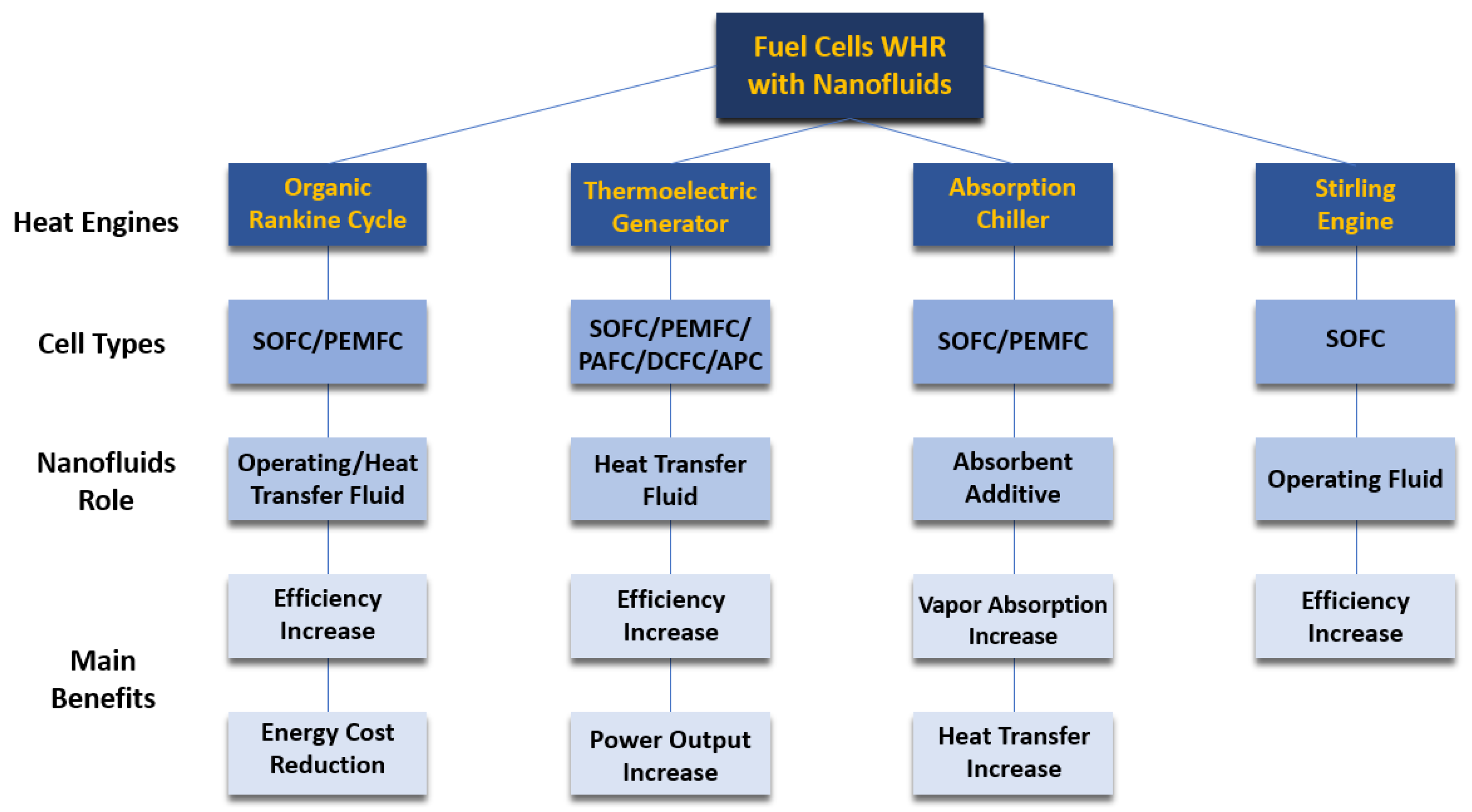
4.5.3. Fuel Cells Waste Heat Recovery

One of the most promising nanofluid uses in the fuel cells technological area is the waste heat recovery approach. The current overview sub-section is dedicated to the use of nanofluids in the different waste heat recovery techniques adequate for fuel cell devices, including Stirling engines, absorption chillers, organic Rankine cycles, and thermoelectric generators. One of the most common ways to recuperate waste heat in fuel cell devices is to drive absorption chillers in the fuel cell for combined cooling power systems producing, at the same time, power, and cooling. This waste heat recovery route was suggested for solid oxide fuel cells [94] and proton-exchange membrane fuel cells [95]. The absorption chillers have received increased research interest since these types of chillers are activated by heat instead of electricity and consequently are considered an environmentally benevolent technological solution and a very suitable alternative to the conventional vapor compression chillers [96]. The ammonia–water and lithium bromide–water are the most common operating mixtures used as absorbent-refrigerant pairs in the absorption chillers. Nanofluids having improved heat transfer and mass transport characteristics can be employed as absorbent material in the absorption chillers to enhance the absorption rate of the refrigerant vapor [96]. Moreover, researchers Zhang et al. [97] experimentally examined the mass transfer performance of lithium bromide–water nanofluids having diverse nanoparticles of alumina, copper, and carbon nanotubes. It was found that the absorption rate of water vapor was closely related to the concentration and size of the nanoparticles. The authors found that the copper nanoparticles portrayed the greatest improvement effect on the absorption process. Furthermore, authors Pourfayaz et al. [98] investigated the performance of a hybrid proton-exchange membrane fuel cell-absorption refrigeration system using aluminum, silver, and alumina aqueous nanofluids as absorbents for increasing the coefficient of performance of the refrigeration system. Authors reported that the silver aqueous nanofluids augmented the overall efficiency of the system by 81%. Beigzadeh et al. [99] analyzed the performance of a solid oxide fuel cell single-effect absorption chiller hybrid system employing nanofluids as heat transfer fluids flowing between the evaporator section of the chiller and the radiator providing the cooling demand for a residential building. The proposed solid oxide fuel cell-absorption chiller hybrid system used the exhaust gases from the solid oxide fuel cell in a heat recovery steam generator to produce the needed steam for the generator of the cooling cycle. The utilized nanofluids were silver, copper, copper oxide, alumina, single-walled carbon nanotubes, and MWCNTs. It was found that the MWCNTs nanofluid was the most effective, augmenting the coefficient of performance and overall thermal efficiency of the system by nearly 32% and 9.7%, respectively. Thermoelectricity generators are another energy conversion technological solution proposed for waste heat recovery in fuel cells converting waste heat into electricity [100]. TEG-based waste heat recovery system has received increased attention for different types of fuel cells, including solid oxide fuel cells [94], proton-exchange membrane fuel cells [95], direct carbon fuel cells [101], and alkaline fuel cells [102]. Despite the many advantages of thermoelectric generators as reliable energy conversion equipment, their poor energy conversion efficiency and the need for a constant heat source are the fundamental limitations that hinder their large-scale use [103]. Also, improving the heat transport at the cold side of the TEG by employing nanofluids can considerably enhance the restricted efficiency of the device and enhance its power output. Moreover, authors Selimefendigil et al. [104] evaluated the performance of a thermoelectric generator using diverse nanofluids, including aqueous carbon nanotubes and silver–magnesium oxide hybrid nanofluids flowing in a channel where the thermoelectric generator module was mounted. The obtained results showed that the power output of the thermoelectric generator increased when nanofluids were employed in the system. Also, the highest output power was achieved with the silver–magnesium oxide hybrid nanofluid. Furthermore, researchers Xing et al. [105] proposed the use of graphene nanoplatelets dispersed in water nanofluid, which enhanced the output power and the conversion efficiency of the thermoelectric generator by approximately 26.4% and 14.7%, respectively. Also, researchers Li et al. [106] evaluated the performance of the thermoelectric generator system employing a 5% vol. graphene-aqueous nanofluid. The authors confirmed increases in the power output, voltage, and conversion efficiency of 21.6%, 11.3%, and 3.5%, respectively. Additionally, authors Li et al. [107] compared the output performance of a thermoelectric generator waste heat recovery process using copper nanoparticles dispersed in ethylene glycol nanofluids and an ethylene glycol-water mixture. It was found that the copper–ethylene glycol nanofluids provided an increase of 14% in the output power in reference to that attained with the ethylene glycol-water mixture. In addition to the power enhancement, the copper–ethylene glycol nanofluid decreased the optimal total area of the thermoelectric generator module, providing a substantial benefit for waste heat recovery systems with space limitations. In essence, nanofluids possessed the ability to ameliorate the performance of the distinct waste heat recovery technologies used in fuel cell generation systems. Figure 8 summarizes the main routes of the fuel cells’ waste heat recovery with the aid of nanofluids.

4.5.4. Chimneys Waste Heat Recovery

The very large worldwide number of chimneys used in several industries, restaurants, and homes, among many others, strongly contribute to global warming and climate change because of their release of large amounts of waste heat. Attempting to reduce such negative effects, authors Eldesoukey et al. [108] analyzed the thermal performance of a thermoelectric generator cooled by a micro-channeled heat spreader using nanofluids for waste heat recovery from a vertical chimney. Researchers employed three-dimensional mathematical models for the thermoelectric generator, microchannels, nanofluids, and heat spreader, which were solved by the Ansys Fluent™ 2021 R1 software. The effects of Joule, Seebeck, and Thomson were considered in the thermoelectric generator model. The obtained results showed that the thermoelectric power increased with increasing heat spreader and microchannel sizes: a 4-fold increase in the microchannels and heat spreader sizes increased the thermoelectric generator output power by 10%. Under these conditions, it achieved a maximum cooling efficiency of nearly 89% and the net output power peak. Also, the micro-channeled heat spreader increased the system net power by around 125% in reference to the normal channel and reduced the needed cooling fluid flow rate. Furthermore, the use of alumina and copper aqueous nanofluids increased the thermoelectric generator output power to a maximum of 4% and 14%, respectively. Nonetheless, the use of nanofluids raised the pumping power demand of the system. Finally, the authors stated that the utilization of nanofluids increased the net output power at low Reynolds numbers and decreased the net output power at higher Reynolds numbers.

4.5.5. Stack Gas Heater Waste Heat Recovery

The impact of using alumina aqueous nanofluids on the thermal performance of an annular enclosure was investigated by authors Dalvand et al. [109], which can be used for waste heat recovery from a stack of a gas heater. In the first heating steps, the temperature of the inner cylindrical increases, whereas the liquid bulk is approximately at the preceding uniform temperature. Consequently, the wall heat flux was considerably increased at the beginning. After that, it was verified that the wall heat flux deteriorated because of the enhancing Rayleigh number Ra and the correspondent creation of flows in the annulus, which led to a temperature increase in the liquid. The use of nanofluids possesses the benefit of enhancing the main key influencing factors, such as the Nusselt number. Nanofluids with increased concentrations of nanoparticles require less time to react to any alterations in the thermal environment. A greater HTC and improved uniformity of the temperature values in the enclosure were attained by choosing larger nanoparticle concentration nanofluids. The experimental results indicated that the HTC and Nusselt number of nanofluids were comparatively enhanced with time, given that the hotter base fluid results in higher thermal conductivity. In view of the results, the research team concluded that in the initial heating phases, there were observed higher temperature increases in the liquid. The water itself and nanofluids exhibited asymptotic evolutions, achieving nanofluids at a higher temperature because of the increased thermal conductivity due to the Brownian motion of the nanoparticles. At low Rayleigh numbers, conduction is the only heat transfer mechanism of fluid flow. As the Rayleigh number increased, it is established a laminar flow regime at the boundary layer, which is restricted by the boundary layers close to the cylinders. The resulting flow enables the liquid to ascend along the hot wall and descend along the cold wall. The temperature uniformity will be obtained if the volumetric concentration of the nanoparticles enlarges to some extent. The more concentrated nanofluids having higher concentration required a shorter period to reach a specific temperature. Hence, the more concentrated nanofluid, the shorter the response time to any alterations in the thermal environment. Also, any augmentation of the time constant will make the fluid respond more slowly to alterations in the thermal environment. Such effects happened whether the ratio between the liquid and gas heat capacities was large or the gas mass flow rate was low. The temperature difference between the outer and inner surfaces of the enclosure increases with increasing concentration of nanoparticles. When the experiments were initiated, the HTC in the enclosure seemed to be high, but it swiftly decreased at a specific time. After that time, it exhibited a fluctuating rising tendency caused by the sequential changes in the thermal conductivity and temperature gradient between the surface and the bulk liquid. The HTC of the liquid became relatively higher in the second half of the time interval because of the increased temperature of the base fluid and, hence, higher increased thermal conductivity. The inner wall peak heat flux was accomplished by the more concentrated nanofluids. During the experiment, the temperature of the inner surface increased by the flue gas, whilst occurred a delay in the bulk liquid temperature increase. As a result, the temperature gradient of the wall and, hence, the heat flux were considerably increased for a certain period. After this period, a wall heat flux degradation was ascertained as the temperature gradient between the wall and liquid bulk was decreased because of the circulating flows and natural convection within the enclosure. Meanwhile, since the nanofluid with higher concentration induced a higher wall heat flux, it was comparatively capable of absorbing more energy under the form of heat. The Nusselt number quickly decreased at first and then showed a fluctuating evolution. Nonetheless, a peak was reached at a specific time, which depended on the concentration of nanoparticles. The temperature ratio diminished over time because of the decreasing ability of the fluids to enhance their thermal energy. Finally, at 0.1% vol. nanofluids, the bulk liquid temperature, HTC, Nusselt number, and heat flux were increased by nearly 3.4%, 20.1%, 7.2%, and 22%, respectively.

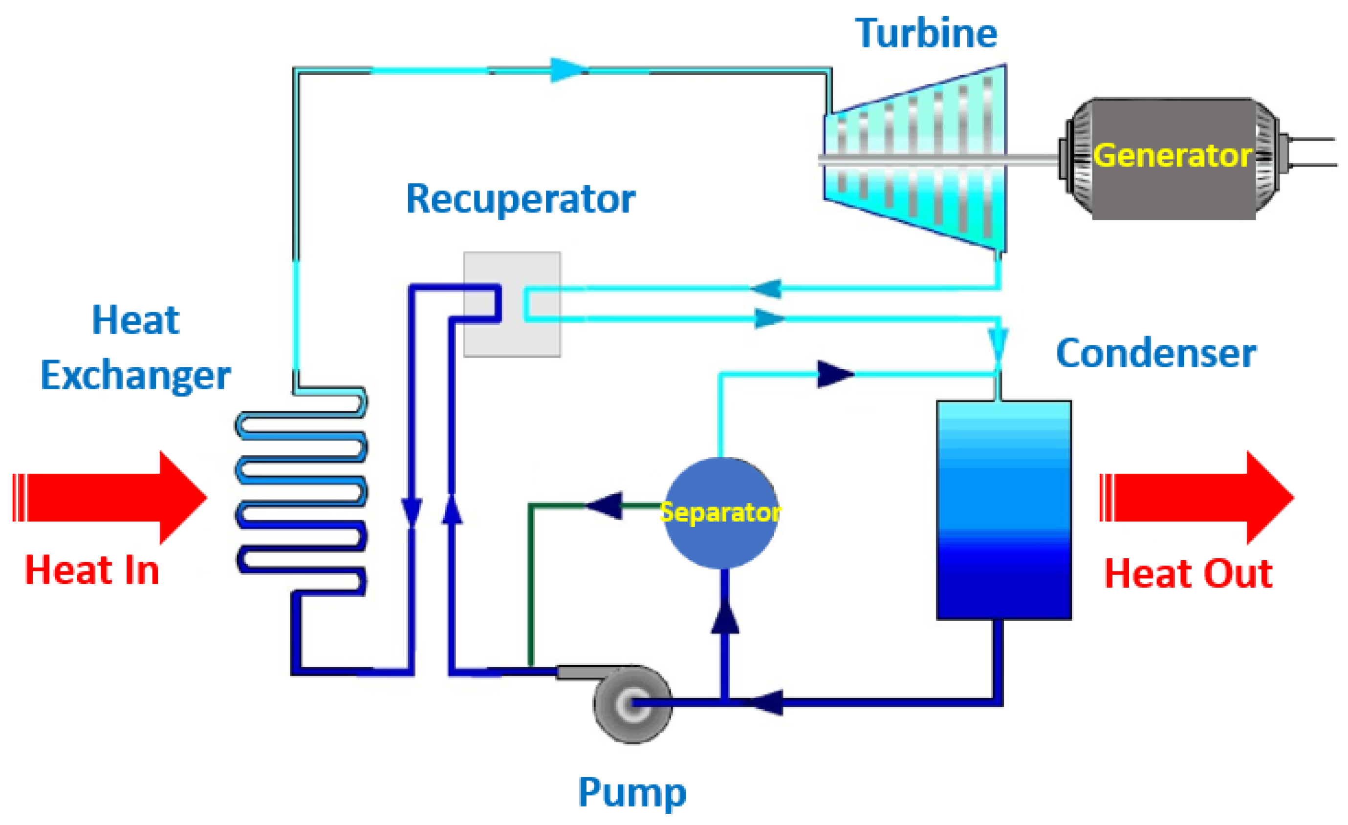
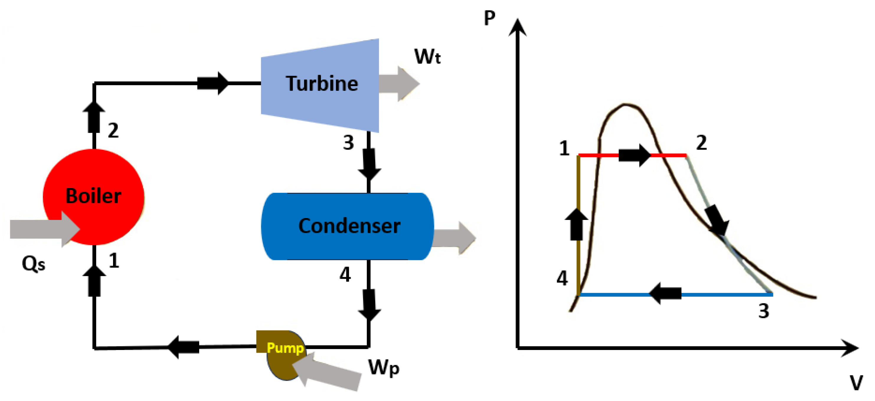
5. Heat-to-Work Waste Heat Recovery with Nanofluids

The heat-to-work waste heat recovery approach can be carried out using diverse heat engines or thermodynamic cycles like the steam and organic Rankine cycle (ORC), Kalina cycle, Stirling engine, and Brayton cycle [110]. The organic Rankine cycle is the most employed for waste heat recovery for work and power, considering the broad range of fluids to be utilized and adequacy for low-grade waste heat [111]. Nonetheless, working fluids to be used in the heat engines should exhibit some special characteristics due to the cyclic character of the phase transition. Also, the thermal fluids operating in the Rankine cycle can be vapor steam, organic compounds, or mixtures of organic compounds, whereas, for instance, the Kalyna cycle normally uses an ammonia-water mixture [112]. Moreover, the application of nanofluids in heat engines is limited and has only been initiated very recently. Nanofluids have been applied as heat transfer fluids in the evaporator and condenser sections to enhance waste heat transport to the operating fluid in essentially the ORC [113]. One initial example is the work developed by Saadatfar et al. [114], in which it was proposed the use of nanofluids in the ORC for decreasing the dimensions of the heat exchanger, evaporator, and condenser of the solar organic Rankine cycle integrated power, heating, and cooling tri-generation. Researchers added silver nanoparticles to the pentane base fluid, increasing the thermal conductivity of 0.136 W·m·−1K−1 of the pentane to nearly 16 W·m·−1K−1 at 0.5% wt. of silver nanoparticles. Also, the obtained results revealed that the use of the nanofluid augmented the overall efficiency by 14%, which was superior to the one of a conventional ORC of 11%. Also, the inclusion of the nanofluid reduced by 30% the exergy destruction, enhanced by 12% the exergy efficiency and reduced by 14% the CO2 emissions. Additionally, a numerical simulation was conducted by researchers Mondejar et al. [115] to evaluate nanofluids as operating fluids in the ORC. Authors elected the nanofluid stability, nanoparticle accumulation and migration to the gas phase, and expander performance as the main concerns of the process. The employed Monte Carlo method showed that the inclusion of a 1% vol. nanofluid resulted in a around 4% decrease in the heat exchanger area. The use of the nanofluid also led to around an 18% rise in the pressure drop, which did not affect the pump power consumption too much. Furthermore, researchers Cavazzini et al. [116] incorporated metal–organic heat carrier nanoparticles in the base fluid R245fa commonly used in the organic Rankine cycle. This type of nanoparticle can extract extra heat because of the endothermic enthalpy of desorption that can conduct a much-increased heat transfer rate. The use of the nanofluid resulted in a considerable decrease of the heat exchanger area per unit power production from the organic Rankine cycle to 7.9–13.8 m2/k·W in comparison to 7.8–15.9 m2/k·W using the pure R245fa base fluid at temperature value between 100 °C to 150 °C. Nanofluids flowing in the heat exchanger in the organic Rankine cycle have been reported to enhance thermal performance and power output. The utilization of graphene and carbon nanotubes aqueous nanofluids as engine coolant enhanced waste heat recovery, having a net power output of nearly 3.8 in two different organic Rankine cycle configurations [117]. The use of silica, alumina, copper oxide, and iron oxide aqueous nanofluids for cooling photovoltaic panels to drive the organic Rankine cycle revealed a 17% enhancement in the efficiency of the system with copper oxide aqueous nanofluids [118]. Also, multi-walled carbon nanotubes dispersed in oil have been used for solar energy storage from solar concentrators attaining a total system efficiency of 21.4% in reference to that of 18.9% attained with the oil base fluid alone [119]. Moreover, researchers Merhpooya et al. [120] evaluated the enhancement in the heat recovery enhancement in combined heat power and solar-driven organic Rankine cycle configurations using nanofluids in a shell and tube heat exchanger. The first step of the work was to simulate the combined heat and power system and the organic Rankine cycle using Aspen HYSIS™ software (https://www.aspentech.com/). Also, aqueous nanofluids of alumina, titanium oxide, copper, and silver were considered at volumetric concentrations of the nanoparticles varying between 0.5% vol. and 4% vol. In view of the obtained results, the authors noted that by adding the nanoparticles to the base fluid, the thermal conductivity, viscosity, HTC, and density increased, and the specific heat decreased. Decreasing the heat capacity of the nanofluid and increasing the viscosity of the nanofluid are deterrents. On the other hand, increasing the thermal conductivity is a positive factor. Hence, the combined result of these factors implies the surface heat transfer area reduction at a certain volume fraction. Because of the large value of Reynolds number and turbulence inside the pipes, the HTC inside the piping is high, and the fluid inside the shell is the controller. Therefore, the increase in the concentration of the nanoparticles induced a rapid increase in the HTC and a decrease in the surface area. The reduction of the specific heat led to the reduction of the average temperature gradient. This factor caused the decrease in the surface area of the employed heat exchanger at a certain concentration of nanoparticles. Moreover, the silver nanoparticles, because of the intrinsic elevated thermal conductivity, had the highest impact on the reduction of surface area and overall cost. Nonetheless, reducing the heat exchanger area will diminish the costs associated with the initial investment, and increasing the pressure drop also increases the annual operating costs, and consequently, the addition of nanoparticles was optimized at a certain point. Considering the organic Rankine cycle unit, authors found that using 1% vol. of silver, copper, alumina, and titanium oxide nanoparticles dispersed in water, the overall cost was reduced by 3.1%, 1.9%, 1.2%, and 0.9%, respectively. Additionally, in the combined heat power system employing 2% vol. of silver, copper, alumina, and titanium oxide aqueous nanofluids, the overall cost decreased by 4.4%, 3%, 1%, and 0.5%, respectively. The main conclusion which authors arrived at was that the use of nanofluids in thermodynamic cycles could appreciably decrease the overall investment cost of heat exchangers and the whole process. Additionally, researchers Prajapati and Patel [121] analyzed and optimized the performance of an organic Rankine cycle-waste heat recovery system using copper oxide aqueous nanofluids in the evaporator and condenser to transfer the heat from the heat source to the operating fluid of the organic Rankine cycle. The authors conclude that the addition of copper oxide nanoparticles to the system enhanced its thermodynamic performance with a thermal efficiency of around 19% and reduced the levelized energy cost by nearly 3.5% in comparison with the conventional organic Rankine cycle. Additionally, authors Prajapati and Patel [17] performed a comparative analysis of the organic Rankine cycle employing copper oxide and alumina aqueous nanofluids in the heat exchanger. The authors noted that the organic Rankine cycle with copper oxide nanofluids demonstrated a better economic performance than that demonstrated by the alumina nanofluids. Furthermore, the author Sami [118] studied the thermal performance of a hybrid system composed of photovoltaic/thermal, organic Rankine cycle, and cooling coil using silica, alumina, copper oxide, and iron oxide nanofluids in a waste heat boiler of the organic Rankine cycle. Among the different heat transfer fluids, the copper oxide nanofluids provided the highest efficiency and greater cooling effect, increasing the efficiency of the hybrid system by around 17%. Figure 9 schematically represents the Kalina cycle, and Figure 10 illustrates the Rankine cycle.

6. Heat-to-Power Waste Heat Recovery with Nanofluids

One adequate mode to convert thermal energy into electricity is to employ thermoelectric generators by the thermoelectric module. The fundamental improving feature of thermal energy storage comes from the heat transfer improvement provided by nanofluids. In the following sub-sections, there are briefly described some illustrative cases concerning the use of nanofluids in thermoelectric generators in heat-to-power waste heat recovery.

6.1. Solar Thermal Energy Waste Heat Recovery

Several studies have been dedicated to recovering heat energy efficiently by using nanofluids and thermoelectric modules. These studies showed that the hot side of the thermoelectric generators was attached to the backside of the photovoltaic panels to absorb the dissipated heat and convert it to electricity. Also, the cold side was cooled by nanofluids and phase-change materials. A first example is the experimental work carried out by authors Soltani et al. [122] in which it was evaluated a system having waste heat recovery from photovoltaic cells using the thermoelectric module and iron oxide or silica aqueous nanofluids. These nanofluids were flowing in the cold side of the thermoelectric module made of bismuth telluride, which can bear the working temperature. Also, the backside of the photovoltaic cells is connected to the hot side of the thermoelectric module. The obtained experimental results confirmed that the silica nanofluid cooling was better than the one provided by the iron oxide nanofluid, given that the former enhanced the power output by nearly 54% as compared with the 52% enhancement obtained when using the iron oxide nanofluid. Moreover, researchers Rajaee et al. [123] studied the combined usage of a cobalt oxide aqueous nanofluid and a nano-enhanced phase change material composed of paraffin and alumina nanoparticles on the performance of a hybrid photovoltaic/thermoelectric generator system. Researchers concluded that operating with the cobalt oxide aqueous nanofluid increased the electrical power generation by nearly 11% in reference to that attained with water. The system, with the introduction of the phase change material, further augmented the electrical efficiency by 4.5%. The authors also emphasized the need for large-scale photovoltaic module experiments to better evaluate the feasibility of the developed cooling system. Moreover, there were performed numerical analysis on waste heat recovery in solar thermal energy systems. Some examples of such analysis were the ones carried out by authors Sami and Marin [124]. The authors investigated the influence of the concentration of nanoparticles dispersed in nanofluids on waste heat recovery efficiency from a photovoltaic cell coupled with a thermoelectric generator working with silica, alumina, copper oxide, and iron oxide nanofluids. The adopted model considered nanofluids as homogeneous, isotropic, incompressible, and Newtonian, having stable inlet temperature and velocity. Researchers arrived at the conclusion that a greater concentration of nanoparticles enhanced the heat released by the photovoltaic cell and, consequently, enhanced power generation by the thermoelectric generator. The obtained results were consistent with the ones found in previous works on photovoltaic/thermoelectric generators in thermoelectric generator-rated systems. Another numeric simulation on the subject was done by researchers Ramamurthi and Nadar [125], who evaluated the thermal performance of a thermoelectric generator-rated system of a parabolic trough collector employing nanofluids and a thermoelectric generator. The authors noted that the energy absorption enhancement was increased by 50% in the case where the nanofluid was used. Additionally, authors Li et al. [106] studied the use of a graphene-aqueous nanofluid on the cold side of a thermoelectric generator in a channeled heat exchanger. The hot plate temperature value was adjusted to mimic the industrial waste heat. The authors reported that the increase of the conversion efficiency, voltage, and output power was nearly 3.5%, 11%, and 22%, respectively. Moreover, considering a waste heat recovery application, researchers Xing et al. [105] conducted numerical work to evaluate the thermal performance of a thermoelectric generator employing graphene-aqueous nanofluids as heat transfer fluids. The authors adopted three-dimensional and steady-state numerical models. The obtained results indicated that nanofluids at 0.1% wt. of graphene increased the power output and conversion efficiency by approximately 26% and 15%, respectively. Moreover, authors Mohammadnia et al. [126] elaborated on an experimental waste heat recovery application using a thermoelectric generator to store extra thermal energy and control the temperature outside the dish cavity of a sterling engine. Such a procedure enabled an enhanced solar concentration and prevented the overheating of the cavity in the middle of the day. At 8:00 AM, the solar irradiation power to the concentrator was around 62 kW. Nearly 4 kW were available by the sterling engine, and an additional 0.8 kW was attained utilizing the thermoelectric generator modules. Researchers found that the thermoelectric generator increased the thermal performance of the system by between 20% and 30% at the beginning and end of the days, respectively. Also, the authors stated that the hybrid dish-sterling-thermoelectric generator system produced approximately 1.3% more electrical energy than the common dish-sterling engine. Nanofluids have been used for waste heat recovery in the heat-to-power route only to increase the heat transfer capability of the primary waste heat source and as refrigerants for the cold and hot sides of thermoelectric generators. In the thermoelectric generators, the weight and investment cost of these waste heat recovery systems should be decreased before use. Another issue is the thermal resistance between the hot reservoir and the thermoelectric generator’s hot side. Additionally, there is the thermal resistance between the thermoelectric generator’s cold side and the heat exchanger that will diminish the efficiency of the system. Such effects can be mitigated by reducing the number of the thermoelectric legs of the thermoelectric generator, utilizing high thermally conductive interface materials such as graphene and carbon nanotubes, and increasing the contact area. Further research work is needed to improve the efficiency of the thermoelectric generators. Accordingly, novel materials and production methodologies of thermoelectric generators, such as flexible thermoelectric generators, are most welcome. The depletion of the existing fossil fuels, in conjunction with the inherent harsh environmental impacts, is the main limitation for the generalized use of these energy resources that must be handled in a careful mode. The decrease in energy demands as the obvious action for maintaining the natural resources sustainability and protecting the environment must be above all considered. Such a way can be paved by implementing high-energy efficiency processes, which should aim to maximize the recovery of the lost energy. Figure 11 schematically illustrates a thermoelectric generator.

6.2. Automotive Waste Heat Recovery

Approximately 70% of the chemical energy in gasoline is lost in the form of heat in the engine of vehicles during the combustion process. Hence, it is reasonable to think that waste heat recovery in the automotive technological area should be a key concern. In this direction, authors Smith and Thornton [127] elaborated a feasibility study for waste heat recovery in vehicles by a thermoelectric generator. Authors reported that waste heat recovery efficiency in vehicles can be between 2% and 3%. Nonetheless, with innovative thermoelectric generators, the same efficiency would get up to 10% to 15%. The research team evaluated a mid-sized automobile, a mid-sized sports vehicle, a Class 8 truck, and a Class 4 truck. It was found that the trucks produced larger amounts of waste heat, so the trucks are the most suitable for the use of a thermoelectric generator to recover these amounts of energy. Moreover, authors Li et al. [107] carried out experimental work and numeric simulation for a vehicle waste heat recovery system with a thermoelectric generator cooled through the flowing of a nanofluid composed of copper nanoparticles dispersed in a water and ethylene glycol mixture. The fundamental output performance influencing factors were studied, including the concentration of nanoparticles, exhaust gas inlet temperature, and the thermoelectric generator’s total area. Authors reported that the used nanofluid could decrease the average temperature of the cold side of the thermoelectric generator and augment the temperature gradient between its hot and cold sides. The nanofluid increased the power output by nearly 13% and the efficiency of the thermoelectric generator by around 14%. Additionally, researchers Karana and Sahoo [128] elaborated a theoretical analysis of the automotive waste heat recovery enhancement using a thermoelectric generator cooled by magnesium oxide and zinc oxide nanofluids. The investigation team reported that the 1% vol. magnesium oxide nanofluid at an exhaust gas inlet temperature of 500 K could increase the conversion efficiency and power output by 10.9% and 11.4%, respectively. Concerning now the zinc oxide nanofluid, the power output might enhance by around 10% in reference to the power output attained with the water/ethylene glycol mixture itself. Considering the same power output, the overall heat transfer area might be diminished by 33% with the magnesium oxide nanofluids, leading to an appreciable cost reduction of the waste heat recovery system. Furthermore, the same authors [129] elaborated a similar study, but this time using silica and zinc oxide nanofluids for cooling the thermoelectric generator. Authors revealed that employing silica nanofluids at an exhaust inlet temperature of 500 K enhanced the power output and conversion efficiency by 11.8 and 11.4%, respectively, with respect to those obtained with the water/ethylene glycol mixture alone. Similarly, researchers Hilmin et al. [130] performed experimental and theoretical work on automotive waste heat recovery employing titanium oxide aqueous nanofluid for cooling a thermoelectric generator. The experimental work was carried out utilizing a car engine running from 600 rpm to 1500 rpm. The peak current, temperature gradient, and thermoelectric generator power were, among others, the parameters which were studied in terms of the cooling ability of the nanofluid. Researchers confirmed that the use of the nanofluid increased the maximum current appreciably to up to nearly 14.4 mA, and the generated power was enhanced to around 28 mW, which was 4% greater than the power generated with only water. Also, the research team found that the temperature difference between the hot and cold sides of the used thermoelectric generator was augmented by nearly 30%. Furthermore, researchers Karana et al. [128] elaborated a theoretical analysis for the performance comparison of automotive waste heat recovery systems with ethylene glycol and water mixture base fluid, zinc oxide, and magnesium oxide nanofluids as coolants for a thermoelectric generator system. The research team found that the highest enhancement of the output power, conversion efficiency, and voltage of the thermoelectric generator system was attained using magnesium oxide, which was followed by the zinc oxide nanofluid and finally by the ethylene glycol and water mixture. The power output and the conversion efficiency at 1% vol. of magnesium oxide nanofluid at an inlet exhaust temperature of 500 K were enhanced by nearly 11.4% and 10.9%, respectively, compared to those obtained with the ethylene glycol and water mixture base fluid. The power output of the thermoelectric generator system increased with increasing concentration of nanoparticles. Also, the authors stated that there was an ideal total area of thermoelectric generators for these to provide the maximum output power of the system. In this sense, it was found that the magnesium oxide nanofluid could reduce the total area of the thermoelectric generators by up to 33% as compared to the total area achieved with the ethylene glycol water mixture. Such a result would bring substantial benefits for the arrangement of thermoelectric generators and reduce the investment cost of the thermoelectric generator system.

7. Recommendations for Future Research Works

  • The weight and overall cost of the thermoelectric generators should be further diminished. Another challenge related to these waste heat recovery devices is the thermal resistance between the hot reservoir and the hot side of the thermoelectric generators. Additionally, the thermal resistance between their cold sides and the heat exchanger will reduce the efficiency. Such effects can be mitigated by reducing the number of thermoelectric legs, employing high thermally conductive interface materials such as graphene and carbon nanotubes, or by alternatively augmenting the contact area;
  • The innovative material and construction methods of the thermoelectric generators, including, for instance, the flexible thermoelectric generator approach, should be further studied and implemented;
  • Further studies are required to obtain guidelines and alternative improvements to overcome the main limitations of the use of thermoelectric generators using nanofluids, namely, the high investment cost and poor energy conversion efficiency;
  • It should be seriously considered the global energy recovery in techno-economic feasible degrees. Considering this, waste heat grade and potential waste heat recovery routes using nanofluids should be in-depth technically and economically assessed to be urgently implemented;
  • There is a pressing demand to further analyze the friction factors and pressure drops associated with the utilization of nanofluids in waste heat recovery approaches since these factors will determine the required pumping power demand;
  • It is suggested to perform further studies on the clustering and sedimentation effects of the nanoparticles included in nanofluids applied in waste heat recovery. The accumulation effect of the suspended nanoparticles is more evident in the circuit stagnation sections in which the fluid velocity is very low. This will deteriorate the heat transfer performance of the system in extended periods of utilization;
  • We welcome studies that elaborate on the evaluation of the corrosive character of some of the added nanoparticles in the nanofluid operating in waste heat recovery processes. The nanoparticles collide with the circuit surfaces and may induce the corrosion of the equipment. This problem should be mitigated in a dual mode, which implies the search for less corrosion-sensitive constitutive materials of the channels and equipment where nanofluids flow and profound studies on the potentially corrosive nature of the included nanoparticles;
  • Waste heat recovery processes with nanofluids, rather than only the heat-to-heat applications, should be further expanded and evaluated. Namely, the ones concerning waste heat recovery involve the use of heat exchangers or heat pipes in which nanofluids act effectively, but they are not employed in further processing;
  • The theoretical and simulation work on the waste’s significant recovery with nanofluids and the associated experimental validation should be further developed;
  • Despite the large number of published techno-economic analyses for nanofluids and waste heat recovery separately, there are only a few studies presenting such assessments for the application of nanofluids in the waste heat recovery technological area. The qualitative evaluation of the technical and economic viability and the environmentally benevolent features inherent to the use of nanofluids in waste heat recovery are well-known by the scientific community. Nonetheless, further quantitative studies are needed instead of qualitative evaluations. Such a route should be accompanied by in-depth studies of waste heat recovery devices and equipment, together with the design and implementation of the process and stream from which the heat will be recovered;
  • More detailed research works are needed to comprehensively evaluate the environmental impacts of the use of nanofluids in waste heat recovery areas comprehensively. Through the life cycle assessment tool, there should be revealed the impacts inherent to the addition of nanoparticles derived from their mining, extraction, purification, and synthesis. All these operations require a considerable amount of energy and fossil fuel global depletion that should be strongly diminished. Also, the disposal of nanofluids after use involves additional toxicity impacting the surrounding ecosystems mainly because of the presence of nanoparticles, which in some cases may hold, for instance, heavy metals;
  • There should be further addressed the applicability and advantageous features of using heat pipe heat exchangers operating with nanofluids for dedicated ventilation and air-conditioning systems. This route will increase the coefficient of performance of the systems and prevent the extra energy demand required for the re-heating and de-humidification processes;
  • It is highly recommended to elaborate further studies on the use of heat pipes working with nanofluids for recovering the sensible heat in systems where the inlet air and return air should always be separated, including surgery rooms and laboratory facilities in which the air must be changed up to 40 times per hour.

8. Conclusions

  • There are currently three different approaches in the waste heat recovery area, namely the heat-to-heat, heat-to-work, and heat-to-power. The heat-to-heat is a straightforward and effective methodology using heat exchangers, heat pipes, thermosyphons, waste heat boilers, and phase-change materials. Nonetheless, the recovered energy is still in the form of heat, which can be considered an efficiency-limited form of energy since it is constrained by the temperature difference;
  • The heat-to-power is a waste heat recovery approach that has great potential since it converts heat into electricity, having broad applicability. It can be performed indirectly by extending the heat-to-work through the connection to an electrical generator. Alternatively, it can also be done via thermoelectric generators. Waste heat recovery through thermoelectric generators could be a rated part for several applications because of its installation easiness and facile operation. The utilization of nanofluids could make the thermoelectric generators yield higher power output;
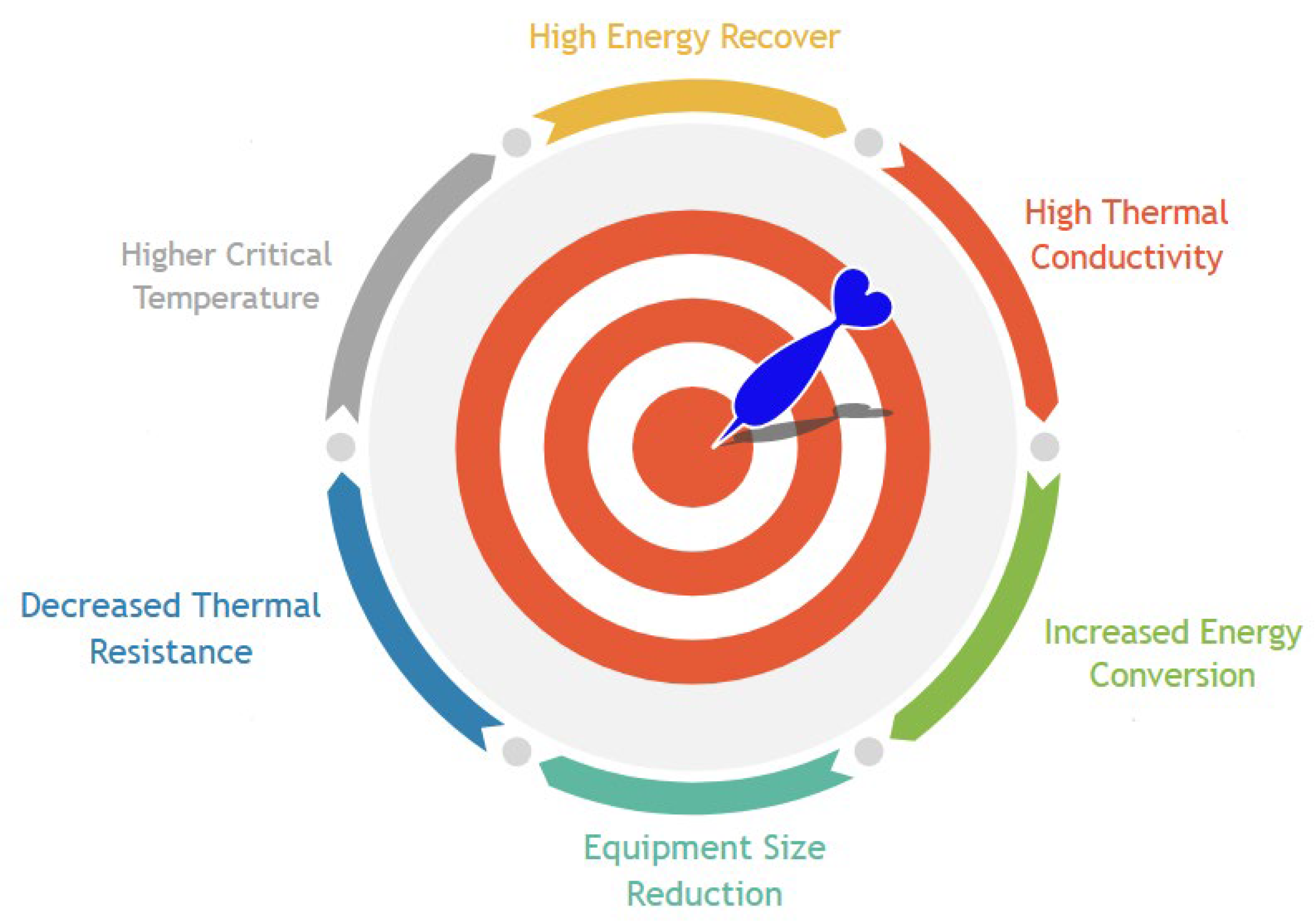
  • Nanofluids have been demonstrated to be an enhanced technological solution for waste heat recovery processes. Their superior thermophysical properties induced by the incorporation of nanoparticles into base fluids, together with the enhanced thermal conductivity and reduced thermal resistance, have been demonstrated to ameliorate the heat transfer performance and recovery rate;
  • Nanofluids used in the heat-to-work waste heat recovery approaches are still limited and fundamentally utilized indirectly to increase heat transport from the primary waste heat source, like in the organic Rankine cycle. The direct utilization of nanofluids as operating fluids in the organic Rankine cycle has been investigated theoretically by numeric simulations with no experimental validation;
  • Nanofluids have been applied so far for waste heat recovery in heat-to-power approaches only to increase the heat transport capability of the primary waste heat source and as refrigerants for the thermoelectric generators’ cold and hot sides;
  • Most studies concerning waste heat recovery in the cement industry have only been conducted on waste gases from the pre-heater and cooler of the clinker. It requires to be further examined intensively to decrease the losses derived from the radiation and convection effects in the cooler. Such losses should be recuperated to improve the efficiency of the clinker cooler.

Author Contributions

Conceptualization, J.P.; methodology, J.P. and A.M. (Ana Moita); software, A.M. (Ana Moita); validation, A.M. (Ana Moita) and A.M. (António Moreira); formal analysis, A.M. (Ana Moita); investigation, J.P.; resources, A.M. (António Moreira); data curation, J.P.; writing—original draft preparation, J.P.; writing—review and editing, J.P.; supervision, A.M. (Ana Moita) and A.M. (António Moreira); project administration, A.M. (António Moreira); funding acquisition, A.M. (António Moreira). All authors have read and agreed to the published version of the manuscript.

Funding

Authors are grateful to the Fundação para a Ciência e a Tecnologia (FCT), Avenida D. Carlos I, 126, 1249-074 Lisboa, Portugal, for partially financing the Project “Estratégias interfaciais de arrefecimento para tecnologias de conversão com elevadas potências de dissipação”, Ref. PTDC/EMETED/7801/2020, António Luís Nobre Moreira, Associação do Instituto Superior Técnico para a Investigação e o Desenvolvimento (IST-ID). The author José Pereira also acknowledges FCT for his PhD Fellowship Ref. 2021.05830.BD.

Institutional Review Board Statement

Not applicable.

Informed Consent Statement

Not applicable.

Data Availability Statement

Data sharing is not applicable.

Conflicts of Interest

Authors declare no conflict of interest.

Nomenclature

Nomenclature:
cpbfSpecific Heat of the Base Fluid [J/kg·K]
cpnfSpecific Heat of the Nanofluid [J/kg·K]
cpnpSpecific Heat of the Nanoparticles [J/kg·K]
cnfSpecific Heat Capacity of the Nanofluid per Unit Volume [J/m3·K]
DInner Diameter of the Tube [m]
dnpAverage Diameter of the Nanoparticles [m]
hHeat Transfer Coefficient [W/m2·K]
KeffEffective Thermal Conductivity [W/m·K]
kbfThermal Conductivity of the Base Fluid [W/m·K]
knfThermal Conductivity of the Nanofluid [W/m·K]
knpThermal Conductivity of the Nanoparticles [W/m·K]
KBBoltzmann’s constant [J/K]
NuNusselt Number
nEmpirical Shape Factor
PePeclet Number
PrPrandtl Number
QVolumetric Flow Rate [m3/s]
rCRadius of the Clusters [m]
RaRayleigh Number
ReReynolds number
tTime [s]
TTemperature [°C] or [K]
umAverage Flow Velocity of the Nanofluid [m/s]
upBrownian Velocity of the Nanoparticles [m/s]
Greek Symbols:
αnfThermal Diffusivity of the Nanofluid [m2/s]
µDynamic Viscosity [Pa·s]
μbfDynamic Viscosity of the Base Fluid [Pa·s]
μnfDynamic Viscosity of the Nanofluid [Pa·s]
νnfKinematic Viscosity of the Nanofluid [m2/s]
ρbfDensity of the Base Fluid [kg/m3]
ρnfDensity of the Nanofluid [kg/m3]
ρnpDensity of the Nanoparticles [kg/m3]
τParticle Relaxation Time [s]
ϕVolumetric Fraction of the Nanoparticles [% vol.]
ψSphericity Factor
ωEmpirical Constant
Abbreviations:
ASHRAEAmerican Society of Heating, Refrigerating, and Air-Conditioning Engineers
CHFCritical Heat Flux
MWCNTMulti-Walled Carbon Nanotubes
HTCHeat Transfer Coefficient
HVACHeating, Ventilation, and Air-Conditioning
FTIRFourier Transform Infrared Spectroscopy
ORCOrganic Rankine Cycle
PSDParticle Size Distribution
SEMScanning Electron Microscopy
TEGThermoelectric Generator
WHRWaste Heat Recovery

References

  1. Brough, D.; Jouhara, H. The aluminium industry: A review on state-of-the-art technologies, environmental impacts and possibilities for waste heat recovery. Int. J. Thermofluids 2020, 1–2, 100007. [Google Scholar] [CrossRef]
  2. Delpech, B.; Milani, M.; Montorsi, L.; Boscardin, D.; Chauhan, A.; Almahmoud, S.; Axcell, B.; Jouhara, H. Energy efficiency enhancement and waste heat recovery in industrial processes by means of the heat pipe technology: Case of the ceramic industry. Energy 2018, 158, 656–665. [Google Scholar] [CrossRef]
  3. Elsaid, J.K.; Sayed, E.T.; Yousef, B.A.; Rabaia, M.K.H.; Abdelkareem, M.A.; Olabi, A. Recent progress on the utilization of waste heat for desalination: A review. Energy Convers. Manag. 2020, 221, 113105. [Google Scholar] [CrossRef]
  4. Liu, Y.; Chen, Y.; Ming, J.; Chen, L.; Shu, C.; Qu, T.; Tan, Q.; Liu, Y.; Asefa, T. Harvesting waste heat energy by promoting H+-ion concentration difference with a fuel cell structure. Nano Energy 2019, 57, 101–107. [Google Scholar] [CrossRef]
  5. Egilegor, B.; Jouhara, H.; Zuazua, J.; Al-Mansour, F.; Plesnik, K.; Montorsi, L.; Manzini, L. ETEKINA: Analysis of the potential for waste heat recovery in three sectors: Aluminium low pressure die casting, steel sector and ceramic tiles manufacturing sector. Int. J. Thermofluids 2020, 1–2, 100002. [Google Scholar] [CrossRef]
  6. Erguvan, M.; MacPhee, D.W. Second law optimization of heat exchangers in waste heat recovery. Int. J. Energy Res. 2019, 43, 5714–5734. [Google Scholar] [CrossRef]
  7. Garcia, S.I.; Garcia, R.F.; Carril, J.C.; Garcia, D.I. A review of thermodynamic cycles used in low temperature recovery systems over the last two years. Renew. Sustain. Energy Rev. 2018, 81, 760–767. [Google Scholar] [CrossRef]
  8. Pan, Q.; Zhao, R.; Jiang, Q.; Gosselin, L. Technological and economic analyses on power generation from the waste heat in a modified aluminum smeltingpot. Int. J. Energy Res. 2020, 44, 1735–1750. [Google Scholar] [CrossRef]
  9. Lee, J.Y.; Lee, J.H.; Kim, T.S. Thermo-economic analysis of using an organic Rankine cycle for heat recovery from both the cell stack and reformer in a PEMFC for power generation. Int. J. Hydrogen Energy 2019, 44, 3876–3890. [Google Scholar] [CrossRef]
  10. Mirhosseini, M.; Rezania, A.; Rosendahl, L. Power optimization and economic evaluation of thermoelectric waste heat recovery system around a rotary cement kiln. J. Clean. Prod. 2019, 232, 1321–1334. [Google Scholar] [CrossRef]
  11. Gao, C.; Lee, S.W.; Yang, Y. Thermally regenerative electrochemical cycle for low-grade heat harvesting. ACS Energy Lett. 2017, 2, 2326–2334. [Google Scholar] [CrossRef]
  12. Zhou, H.; Liu, P. High Seebeck Coefficient Electrochemical Thermocells for Efficient Waste Heat Recovery. CS Appl. Energy Mater. 2018, 1, 1424–1428. [Google Scholar] [CrossRef]
  13. Mai, V.-P.; Haung, W.-H.; Yang, R.-J. Charge Regulation and pH Effects on Thermo-Osmotic Conversion. Nanomaterials 2022, 12, 2774. [Google Scholar] [CrossRef]
  14. Straub, A.P.; Yip, N.Y.; Lin, S.; Lee, J.; Elimelech, M. Harvesting low-grade heat energy using thermo-osmotic vapour transport through nanoporous membranes. Nat. Energy 2016, 1, 16090. [Google Scholar] [CrossRef]
  15. Pandya, S.; Velarde, G.; Zhang, L.; Wilbur, J.D.; Smith, A.; Hanrahan, B.; Dames, C.; Martin, L.W. New approach to waste-heat energy harvesting: Pyroelectric energy conversion. NPG Asia Mater. 2019, 11, 26. [Google Scholar] [CrossRef]
  16. Ali, N.; Teixeira, J.A.; Addali, A. A review on nanofluids: Fabrication, stability, and thermophysical properties. J. Nanomater. 2018, 2018, 6978130. [Google Scholar] [CrossRef] [Green Version]
  17. Prajapati, P.P.; Patel, V.K. Comparative analysis of nanofluid-based Organic Rankine Cycle through thermoeconomic optimization. Heat Transf.—Asian Res. 2019, 48, 3013–3038. [Google Scholar] [CrossRef]
  18. Aljaghtham, M.; Celik, E. Design optimization of oil pan thermoelectric generator to recover waste heat from internal combustion engines. Energy 2020, 200, 117547. [Google Scholar] [CrossRef]
  19. US-EPA. Greenhouse Gas Equivalence Calculator. 2023. Available online: https://www.epa.gov/energy/greenhouse-gas-equivalencies-calculator (accessed on 11 July 2023).
  20. Dal Magro, F.; Savino, S.; Meneghetti, A.; Nardin, G. Coupling waste heat extraction by phase change materials with superheated steam generation in the steel industry. Energy 2017, 137, 1107–1118. [Google Scholar] [CrossRef]
  21. Zaric, M.; Stijepovic, M.Z.; Linke, P.; Stajic-Trosic, J.; Bugarski, B.; Kijevcanin, M. Targeting heat recovery and reuse in industrial zone. Chem. Ind. Chem. Eng. Q. 2017, 23, 73–82. [Google Scholar] [CrossRef] [Green Version]
  22. Forman, C.; Muritala, I.K.; Pardemman, R.; Meyer, B. Estimating the global waste heat potential. Renew. Sustain. Energy Rev. 2016, 57, 1568–1579. [Google Scholar] [CrossRef]
  23. Vance, D.; Nimbalkar, S.; Thekdi, A.; Armstrong, K.; Wenning, T.; Cresko, J.; Jin, M. Estimation of and barriers to waste heat recovery from harsh environments in industrial processes. J. Clean. Prod. 2019, 222, 539–549. [Google Scholar] [CrossRef]
  24. Cheng, Z.; Guo, Z.; Tan, Z.; Yang, J.; Wang, Q. Waste heat recovery from high-temperature solid granular materials: Energy challenges and opportunities. Renew. Sustain. Energy Rev. 2019, 116, 109428. [Google Scholar] [CrossRef]
  25. Lokare, O.R.; Tavakkoli, S.; Rodriguez, G.; Khanna, V.; Vidic, R.D. Integrating membrane distillation with waste heat from natural gas compressor stations for produced water treatment in Pennsylvania. Desalination 2017, 413, 144–153. [Google Scholar] [CrossRef] [Green Version]
  26. Maxwell, J.C. A Treatise on Electricity and Magnetism; Clarendon Press: Clarendon, UK, 1973. [Google Scholar]
  27. Hamilton, R.L.; Crosser, O.K. Thermal conductivity of heterogeneous two-component systems. IEC Fundam 1962, 1, 187–191. [Google Scholar] [CrossRef]
  28. Pak, B.C.; Cho, Y.I. Hydrodynamic and heat transfer study of dispersed fluids with submicron metallic oxide particles. Exp. Heat Transf. Int. J. 1998, 11, 151–170. [Google Scholar] [CrossRef]
  29. Xuan, Y.; Li, Q.; Hu, W. Aggregation structure and thermal conductivity of nanofluids. AIChE J. 2003, 49, 1038–1043. [Google Scholar] [CrossRef]
  30. Yang, B. Thermal conductivity equations based on Brownian motion in suspensions of nanoparticles (nanofluids). J. Heat Transf. 2008, 130, 042408. [Google Scholar] [CrossRef]
  31. Xuan, Y.; Roetzel, W. Conceptions for heat transfer correlation of nanofluids. Int. J. Heat Mass Transf. 2002, 43, 3701–3707. [Google Scholar] [CrossRef]
  32. Zhou, L.P.; Wang, B.X.; Peng, X.F.; Du, X.Z.; Yang, Y.P. On the specific heat capacity of CuO nanofluid. Adv. Mech. Eng. 2010, 2, 172085. [Google Scholar] [CrossRef] [Green Version]
  33. Einstein, A. A new determination of molecular dimensions. Ann. Phys. 1906, 19, 2. [Google Scholar]
  34. Brinkman, H.C. The viscosity of concentrated suspensions and solution. J. Chem. Phys. 1952, 20, 571–581. [Google Scholar] [CrossRef]
  35. Abu-Nada, E. Effects of variable viscosity and thermal conductivity of Al2O3–water nanofluid on heat transfer enhancement in natural convection. Int. J. Heat Fluid Flow 2009, 30, 679–690. [Google Scholar] [CrossRef]
  36. Namburu, P.K.; Das, D.K.; Tanguturi, K.M.; Vajjha, R.S. Numerical study of turbulent flow and heat transfer characteristics of nanofluids considering variable properties. Int. J. Therm. Sci. 2009, 48, 290–302. [Google Scholar] [CrossRef]
  37. Nguyen, C.T.; Desgranges, F.; Roy, G.; Galanis, N.; Maré, T.; Boucher, S.; Mintsa, H.A. Temperature and particle-size dependent viscosity data for water-based nanofluids–hysteresis phenomenon. Int. J. Heat Fluid Flow 2007, 28, 1492–1506. [Google Scholar] [CrossRef]
  38. Wang, X.; Xu, X.; Choi, S.U.S. Thermal conductivity of nanoparticle-fluid mixture. J. Thermophys. Heat Transf. 1999, 13, 474–480. [Google Scholar] [CrossRef]
  39. Naddaf, A.; Heris, S.Z. Density and rheological properties of different nanofluids based on diesel oil at different mass concentrations: An experimental study. J. Therm. Anal. Calorim. 2019, 135, 1229–1242. [Google Scholar] [CrossRef]
  40. Barbés, B.; Páramo, R.; Blanco, E.; Casanova, C. Thermal conductivity and specific heat capacity measurements of CuO nanofluids. J. Therm. Anal. Calorim. 2014, 115, 1883–1891. [Google Scholar] [CrossRef]
  41. Xie, H.; Chen, L. Adjustable thermal conductivity in carbon nanotube nanofluids. Phys. Lett. A 2009, 373, 1861–1864. [Google Scholar] [CrossRef]
  42. Timofeeva, E.V.; Routbort, J.L.; Singh, D. Particle shape effects on thermophysical properties of alumina nanofluids. J. Appl. Phys. 2009, 106, 014304. [Google Scholar] [CrossRef]
  43. Kim, H.J.; Lee, S.H.; Lee, J.H.; Jang, S.P. Effect of particle shape on suspension stability and thermal conductivities of water-based bohemite alumina nanofluids. Energy 2015, 90, 1290–1297. [Google Scholar] [CrossRef]
  44. Duangthongsuk, W.; Wongwises, S. An experimental study on the heat transfer performance and pressure drop of TiO2-water nanofluids flowing under a turbulent flow regime. Int. J. Heat Mass Transf. 2010, 53, 334–344. [Google Scholar] [CrossRef]
  45. Khairul, M.A.; Shah, K.; Doroodchi, E.; Azizian, R.; Moghtaderi, B. Effects of surfactant on stability and thermo-physical properties of metal oxide nanofluids. Int. J. Heat Mass Transf. 2016, 98, 778–787. [Google Scholar] [CrossRef]
  46. Heris, S.Z.; Noie, S.H.; Talaii, E.; Sargolzaei, J. Numerical investigation of Al2O3/water nanofluid laminar convective heat transfer through triangular ducts. Nanoscale Res. Lett. 2011, 6, 179. [Google Scholar] [CrossRef] [PubMed] [Green Version]
  47. Xuan, Y.; Li, Q. Investigation on convective heat transfer and flow features of nanofluids. J. Heat Transf. 2003, 125, 151–155. [Google Scholar] [CrossRef] [Green Version]
  48. Maiga, S.B.; Nguyen, C.T.; Galanis, N.; Roy, G.; Maré, T.; Coqueux, M. Heat transfer enhancement in turbulent tube flow using Al2O3 nanoparticle suspension. Int. J. Numer. Methods Heat Fluid Flow 2006, 16, 275–292. [Google Scholar] [CrossRef]
  49. Hatami, M.; Ganji, D.; Gorji-Bandpy, M. A review of different heat exchangers designs for increasing the diesel exhaust waste heat recovery. Renew. Sustain. Energy Rev. 2014, 37, 168–181. [Google Scholar] [CrossRef]
  50. Fakheri, A. Heat Exchanger Efficiency. J. Heat Transfer. 2007, 129, 1268–1276. [Google Scholar] [CrossRef]
  51. Pordanjani, A.H.; Aghakhani, S.; Afrand, M.; Mahmoudi, B.; Mahian, O.; Wongwises, S. An updated review on application of nanofluids in heat exchangers for saving energy. Energy Convers. Manag. 2019, 198, 111886. [Google Scholar] [CrossRef]
  52. Zamzamian, A.; Oskouie, S.N.; Doosthoseini, A.; Joneidi, A.; Pazouki, M. Experimental investigation of forced convective heat transfer coefficient in nanofluids of Al2O3/EG and CuO/EG in a double pipe and plate heat exchangers under turbulent flow. Exp. Therm. Fluid Sci. 2011, 35, 495–502. [Google Scholar] [CrossRef]
  53. Attalla, M.; Maghrabie, H.M. An experimental study on heat transfer and fluid flow of rough plate heat exchanger using Al2O3/water nanofluid. Exp. Heat Transf. 2020, 33, 261–281. [Google Scholar] [CrossRef]
  54. Leong, K.; Saidur, R.; Mahlia, T.; Yau, Y. Modeling of shell and tube heat recovery exchanger operated with nanofluid based coolants. Int. J. Heat Mass Transf. 2012, 55, 808–816. [Google Scholar] [CrossRef]
  55. Kong, R.; Asanakham, A.; Deethayat, T.; Kiatsiriroat, T. Heat transfer characteristics of deionized water-based graphene nanofluids in helical coiled heat exchanger for waste heat recovery of combustion stack gas. Heat Mass Transf. 2019, 55, 385–396. [Google Scholar] [CrossRef]
  56. Ebrahimi, M.; Akhoundi, M. A feasibility study and economic analysis for application of nanofluids in waste heat recovery. Energy Equip. Syst. 2016, 4, 205–214. [Google Scholar] [CrossRef]
  57. Shafieian, A.; Khiadani, M.; Nosrati, A. A review of latest developments, progress, and applications of heat pipe solar collectors. Renew. Sustain. Energy Rev. 2018, 95, 273–304. [Google Scholar] [CrossRef]
  58. Noie-Baghban, S.H.; Majideian, G. Waste heat recovery using heat pipe heat exchanger (HPHE) for surgery rooms in hospitals. Appl. Therm. Eng. 2000, 20, 1271–1282. [Google Scholar] [CrossRef]
  59. Martınez, F.J.R.; Plasencia, M.A.A.-G.; Gomez, E.V.; Diez, F.V.; Martin, R.H. Design and experimental study of a mixed energy recovery system, heat pipes and indirect evaporative equipment for air conditioning. Energy Build. 2003, 35, 1021–1030. [Google Scholar] [CrossRef]
  60. Lukitobudi, A.; Akbarzadeh, A.; Johnson, P.; Hendy, P. Design, construction and testing of a thermosyphon heat exchanger for medium temperature heat recovery in bakeries. Heat Recovery Syst. CHP 1995, 15, 481–491. [Google Scholar] [CrossRef]
  61. Yang, Y.; Yuan, X.; Lin, G. Waste heat recovery using heat pipe heat exchanger for heating automobile using exhaust gas. Appl. Therm. Eng. 2003, 23, 367–372. [Google Scholar] [CrossRef]
  62. Riffat, S.; Gan, G. Determination of effectiveness of heat-pipe heat recovery for naturally-ventilated buildings. Appl. Therm. Eng. 1998, 18, 121–130. [Google Scholar] [CrossRef]
  63. Wu, X.P.; Johnson, P.; Akbarzadeh, A. Application of heat pipe heat exchangers to humidity control in air-conditioning systems. Appl. Therm. Eng. 1997, 17, 561–568. [Google Scholar] [CrossRef]
  64. Ghosayeshi, H.R.; Safaei, M.R.; Goodarzi, M.; Dahari, M. Particle size and type effects on heat transfer enhancement of Ferro-nanofluids in a pulsating heat pipe. Powder Technol. 2016, 301, 1218–1226. [Google Scholar] [CrossRef]
  65. Kang, S.-W.; Wang, Y.-C.; Liu, Y.-C.; Lo, H.-M. Visualization and thermal resistance measurements for a magnetic nanofluid pulsating heat pipe. Appl. Therm. Eng. 2017, 126, 1044–1150. [Google Scholar] [CrossRef]
  66. Ramachandran, R.; Ganesan, K.; Rajkumar, M.R.; Asirvatham, L.G.; Wongwises, S. Comparative study of the effect of hybrid nanoparticle on the thermal performance of cylindrical screen mesh heat pipe. Int. Commun. Heat Mass Transf. 2016, 76, 294–300. [Google Scholar] [CrossRef]
  67. Zufar, M.; Gunnasegaran, P.; Kumar, H.M.; Ng, K.C. Numerical and experimental investigations of hybrid nanofluids on pulsating heat pipe performance. Int. J. Heat Mass Transf. 2020, 146, 118887. [Google Scholar] [CrossRef]
  68. Qian, N.; Jiang, F.; Chen, J.; Fu, Y.; Zhang, J.; Xu, J. Heat transfer enhancement by diamond nanofluid in gravity heat pipe for waste heat recovery. Funct. Diam. 2022, 2, 236–244. [Google Scholar] [CrossRef]
  69. Chaudhari, V.; Dharmadhikari, M.; Kolhe, V. Performance Evaluation of Heat Pipe Heat Exchanger with Nanofluid: An Experimental Study. Lett. Appl. NanoBioScience 2023, 12, 121. [Google Scholar] [CrossRef]
  70. Shinde, S.M.; Arakerimath, R.R.; Bansod, P.J. Performance Study of Heat Pipe Heat Exchanger Using Nanofluid (BN) Used in Boiler Plant- Experimental Study. Int. J. Innov. Res. Sci. Eng. Technol. 2017, 6, 20941–20949. [Google Scholar] [CrossRef]
  71. Thakur, P.; Kumar, N.; Sonawane, S.S. Enhancement of pool boiling performance using MWCNT based nanofluids: A sustainable method for the wastewater and incinerator heat recovery. Sustain. Energy Technol. Assess. 2021, 45, 101115. [Google Scholar] [CrossRef]
  72. Tao, Y.; He, Y.-L. A review of phase change material and performance enhancement method for latent heat storage system. Renew. Sustain. Energy Rev. 2018, 93, 245–259. [Google Scholar] [CrossRef]
  73. Rathod, M.K.; Banerjee, J. Thermal stability of phase change materials used in latent heat energy storage systems: A review. Renew. Sustain. Energy Rev. 2013, 18, 246–258. [Google Scholar] [CrossRef]
  74. Nomura, T.; Okinaka, N.; Akiyama, T. Waste heat transportation system, using phase change material (PCM) from steelworks to chemical plant. Resour. Conserv. Recycl. 2010, 54, 1000–1006. [Google Scholar] [CrossRef]
  75. Begum, L.; Hasan, M.; Vatistas, G.H. Energy storage in a complex heat storage unit using commercial grade phase change materials: Effect of convective heat transfer boundary conditions. Appl. Therm. Eng. 2018, 131, 621–641. [Google Scholar] [CrossRef]
  76. Milian, Y.E.; Gutierrez, A.; Grageda, M.; Ushak, S. A review on encapsulation techniques for inorganic phase change materials and the influence on their thermophysical properties. Renew. Sustain. Energy Rev. 2017, 73, 983–999. [Google Scholar] [CrossRef]
  77. Qu, Y.; Wang, S.; Zhou, D.; Tian, Y. Experimental study on thermal conductivity of paraffin-based shape-stabilized phase change material with hybrid carbon nano-additives. Renew. Energy 2020, 146, 2637–2645. [Google Scholar] [CrossRef]
  78. Wickramaratne, C.; Dhau, J.S.; Kamal, R.; Myers, P.; Goswami, D.Y.; Stefanakos, E. Macro-encapsulation and characterization of chloride based inorganic Phase change materials for high temperature thermal energy storage systems. Appl. Energy 2018, 221, 587–596. [Google Scholar] [CrossRef]
  79. Jeyaseelan, T.R.; Azhagesan, N.; Pethurajan, V. Thermal characterization of NaNO3/KNO3 with different concentrations of Al2O3 and TiO2 nanoparticles. J. Therm. Anal. Calorim. 2019, 136, 235–242. [Google Scholar] [CrossRef]
  80. Firouzfar, E.; Soltanieh, M.; Noie, S.H.; Saidi, S.H. Energy saving in HVAC systems using nanofluid. Appl. Therm. Eng. 2011, 31, 1543–1545. [Google Scholar] [CrossRef]
  81. Byrne, P.; Miriel, J.; Lénat, Y. Experimental study of an air-source heat pump for simultaneous heating and cooling–part 2: Dynamic behavior and two-phase thermosiphon defrosting technique. Appl. Therm. Eng. 2011, 88, 3072–3078. [Google Scholar] [CrossRef] [Green Version]
  82. Jouhara, H.; Merchant, H. Experimental investigation of a thermosyphon based heat exchanger used in energy efficient air handling units. Energy 2012, 39, 82–89. [Google Scholar] [CrossRef]
  83. Danielewicz, J.; Sayegh, M.A.; Sniechowska, B.; Szulgowska-Zgrzywa, M.; Jouhara, H. Experimental and analytical performance investigation of air to air two phase closed thermosyphon based heat exchangers. Energy 2014, 77, 82–87. [Google Scholar] [CrossRef] [Green Version]
  84. Meena, P.; Tammasaeng, P.; Kanphirom, J.; Ponkho, A.; Setwong, S. Enhancement of the performance heat transfer of a thermosyphon with fin and without fin heat exchangers using Cu-nanofluid as working fluids. J. Eng. Thermophys. 2014, 23, 331–340. [Google Scholar] [CrossRef]
  85. Zhang, L.; Zhang, Y.-F. Research on Energy Saving Potential for Dedicated Ventilation Systems Based on Heat Recovery Technology. Energies 2014, 7, 4261–4280. [Google Scholar] [CrossRef] [Green Version]
  86. Ahmadzadehtalatapeh, M. Improving the Energy Performance of HVAC Systems in Operating Theatres by Using Heat Recovery Devices. Int. J. Renew. Energy Res. 2014, 4, 586–592. [Google Scholar] [CrossRef]
  87. Karamarkovic, V.; Marasevic, M.; Karamarkovic, R.; Karamarkovic, M. Recuperator for waste heat recovery from rotary kilns. Appl. Therm. Eng. 2013, 54, 470–480. [Google Scholar] [CrossRef]
  88. Heinz, A.; Streicher, W. Application of Phase Change Materials and PCM Slurries for Thermal Energy Storage. In Proceedings of the 10th International Conference on Thermal Energy Storage, Pomona, CA, USA, 31 May 2006. [Google Scholar]
  89. Abedin, A.H.; Marc, A.R. A Critical Review of Thermo-Chemical Energy Storage Systems. Open Renew. Energy J. 2011, 4, 42–46. [Google Scholar] [CrossRef] [Green Version]
  90. Sharma, A.; Tyagi, V.V.; Chen, C.R.; Buddhi, D. Review on Thermal Energy Storage with Phase Change Materials and Applications. Renew. Sustain. Energy Rev. 2009, 13, 318–345. [Google Scholar] [CrossRef]
  91. Khurana, S.; Banerjee, R.; Gaitonde, U. Energy balance and cogeneration for cement plants. Appl. Therm. Eng. 2002, 22, 485–494. [Google Scholar] [CrossRef]
  92. Madlool, N.A.; Saidur, R.; Hossain, M.S.; Rahim, N.A. A critical review on energy use and savings in the cement industries. Renew. Sustain. Energy Rev. 2011, 15, 2042–2060. [Google Scholar] [CrossRef]
  93. Madlool, N.A.; Hadi, A.A.A. Enhancement of waste heat recovery by using Cu nanoparticles in cement industries. Int. Sci. J.-J. Environ. Sci. 2015. [Google Scholar]
  94. Sulaiman, M.S.; Mohamed, W.; Singh, B.; Ghazali, M.F. Validation of a waste heat recovery model for a 1kW PEM fuel cell using thermoelectric generator. IOP Conf. Ser. Mater. Sci. Eng. 2017, 226, 012148. [Google Scholar] [CrossRef]
  95. Sehgal, S.; Alvarado, J.L.; Hassan, I.G.; Kadam, S.T. A comprehensive review of recent developments in falling-film, spray, bubble and microchannel absorbers for absorption systems. Renew. Sustain. Energy Rev. 2021, 142, 110807. [Google Scholar] [CrossRef]
  96. Wang, G.; Zhang, Q.; Zeng, M.; Xu, R.; Xie, G.; Chu, W. Investigation on mass transfer characteristics of the falling film absorption of LiBr aqueous solution added with nanoparticles. Int. J. Refrig 2018, 89, 149–158. [Google Scholar] [CrossRef]
  97. Zhang, L.; Fu, Z.; Liu, Y.; Jin, L.; Zhang, Q.; Hu, W. Experimental study on enhancement of falling film absorption process by adding various nanoparticles. Int. Commun. Heat Mass Transf. 2018, 92, 100–106. [Google Scholar] [CrossRef]
  98. Pourfayaz, F.; Imani, M.; Mehrpooya, M.; Shirmohammadi, R. Process development and exergy analysis of a novel hybrid fuel cell-absorption refrigeration system utilizing nanofluid as the absorbent liquid. Int. J. Refrig. 2019, 97, 31–41. [Google Scholar] [CrossRef]
  99. Beigzadeh, M.; Pourfayaz, F.; Ahmadi, M.H. Modeling and improvement of solid oxide fuel cell-single effect absorption chiller hybrid system by using nanofluids as heat transporters. Appl. Therm. Eng. 2020, 166, 114707. [Google Scholar] [CrossRef]
  100. Baroutaji, A.; Arjunan, A.; Ramadan, M.; Robinson, J.; Alaswad, A.; Abdelkareem, M.A.; Olabi, A.-G. Advancements and prospects of thermal management and waste heat recovery of PEMFC. Int. J. Thermofluids 2021, 9, 100064. [Google Scholar] [CrossRef]
  101. Zhao, M.; Zhang, H.; Hu, Z.; Zhang, Z.; Zhang, J. Performance characteristics of a direct carbon fuel cell/thermoelectric generator hybrid system. Energy Convers. Manag. 2015, 89, 683–689. [Google Scholar] [CrossRef]
  102. Yang, P.; Zhu, Y.; Zhang, P.; Zhang, H.; Hu, Z.; Zhang, J. Performance evaluation of an alkaline fuel cell/thermoelectric generator hybrid system. Int. J. Hydrogen Energy 2014, 39, 11756–11762. [Google Scholar] [CrossRef]
  103. Jouhara, H.; Zabnienska-Gora, A.; Khordehgah, N.; Doraghi, Q.; Ahmad, L.; Norman, L.; Axcell, B.; Wrobel, L.; Dai, S. Thermoelectric generator (TEG) technologies and applications. Int. J. Thermofluids 2021, 9, 100063. [Google Scholar] [CrossRef]
  104. Selimefendigil, F.; Okulu, D.; Mamur, H. Numerical analysis for performance enhancement of thermoelectric generator modules by using CNT–water and hybrid Ag/MgO–water nanofluids. J. Therm. Anal. Calorim. 2020, 143, 1611–1621. [Google Scholar] [CrossRef]
  105. Xing, J.-J.; Wu, Z.-H.; Xie, H.-Q.; Wang, Y.-Y.; Li, Y.-H.; Mao, J.-H. Performance of thermoelectric generator with graphene nanofluid cooling. Chin. Phys. B 2017, 26, 104401. [Google Scholar] [CrossRef]
  106. Li, Y.; Wu, Z.; Xie, H.; Xing, J.; Mao, J.; Wang, Y.; Li, Z. Study on the performance of TEG with heat transfer enhancement using graphene-water nanofluid for a TEG cooling system. Sci. China Technol. Sci. 2017, 60, 1168–1174. [Google Scholar] [CrossRef]
  107. Li, Z.; Li, W.; Chen, Z. Performance analysis of thermoelectric based automotive waste heat recovery system with nanofluid coolant. Energies 2017, 10, 1489. [Google Scholar] [CrossRef] [Green Version]
  108. Eldesoukey, A.; Hassan, H. Study of the performance of thermoelectric generator for waste heat recovery from chimney: Impact of nanofluid-microchannel cooling system. Environ. Sci. Pollut. Res. 2022, 29, 74242–74263. [Google Scholar] [CrossRef]
  109. Dalvand, H.M.; Moghadam, A.J. Experimental investigation of a water/nanofluid jacket performance in stack heat recovery. J. Therm. Anal. Calorim. 2019, 135, 657–669. [Google Scholar] [CrossRef]
  110. Jouhara, H.; Khordehgah, N.; Almahmoud, S.; Delpech, B.; Chauhan, A.; Tassou, S.A. Waste heat recovery technologies and applications. Therm. Sci. Eng. Prog. 2018, 6, 268–289. [Google Scholar] [CrossRef]
  111. Júnior, E.P.B.; Arrieta, M.D.P.; Arrieta, F.R.P.; Silva, C.H.F. Assessment of a Kalina cycle for waste heat recovery in the cement industry. Appl. Therm. Eng. 2019, 147, 421–437. [Google Scholar] [CrossRef]
  112. Zhang, Z.; Chen, L.; Yang, B.; Ge, Y.; Sun, F. Thermodynamic analysis and optimization of an air Brayton cycle for recovering waste heat of blast furnace slag. Appl. Therm. Eng. 2015, 90, 742–748. [Google Scholar] [CrossRef]
  113. Bellos, E.; Tzivanidis, C. Parametric analysis and optimization of an Organic Rankine Cycle with nanofluid based solar parabolic trough collectors. Renew. Energy 2017, 114, 1376–1393. [Google Scholar] [CrossRef]
  114. Saadatfar, B.; Fakhrai, R.; Fransson, T. Conceptual modeling of nano fluid ORC for solar thermal polygeneration. Energy Procedia 2014, 57, 2696–2705. [Google Scholar] [CrossRef] [Green Version]
  115. Mondejar, M.E.; Andreasen, J.G.; Regidor, M.; Riva, S.; Kontogeorgis, G.; Persico, G.; Haglind, F. Prospects of the use of nanofluids as working fluids for organic Rankine cycle power systems. Energy Procedia 2017, 129, 160–167. [Google Scholar] [CrossRef] [Green Version]
  116. Cavazzini, G.; Bari, S.; McGrail, P.; Benedetti, V.; Pavesi, G.; Ardizzon, G. Contribution of Metal-Organic-Heat Carrier nanoparticles in a R245fa low-grade heat recovery Organic Rankine Cycle. Energy Convers. Manag. 2019, 199, 111960. [Google Scholar] [CrossRef]
  117. Huang, H.; Zhu, Z.; Yan, B. Comparison of the performance of two different Dual-loop organic Rankine cycles (DORC) with nanofluid for engine waste heat recovery. Energy Convers. Manag. 2016, 126, 99–109. [Google Scholar] [CrossRef]
  118. Sami, S. Analysis of Nanofluids Behavior in a PV-Thermal-Driven Organic Rankine Cycle with Cooling Capability. Appl. Syst. Innov. 2020, 3, 12. [Google Scholar] [CrossRef] [Green Version]
  119. Refiei, A.; Loni, R.; Najafi, G.; Sahin, A.; Bellos, E. Effect of use of MWCNT/oil nanofluid on the performance of solar organic Rankine cycle. Energy Rep. 2020, 6, 782–794. [Google Scholar] [CrossRef]
  120. Mehrpooya, M.; Dehqani, M.; Mousavi, S.A. Heat transfer and economic analysis of using various nanofluids in shell and tube heat exchangers for the cogeneration and solar-driven organic Rankine cycle systems. Int. J. Low-Carbon Technol. 2021, 17, 11–22. [Google Scholar] [CrossRef]
  121. Prajapati, P.P.; Patel, V.K. Thermo-economic optimization of a nanofluid based organic Rankine cycle: A multi-objective study and analysis. Therm. Sci. Eng. Prog. 2020, 17, 100381. [Google Scholar] [CrossRef]
  122. Soltani, S.; Kasaeian, A.; Sarrafha, H.; Wen, D. An experimental investigation of a hybrid photovoltaic/thermoelectric system with nanofluid application. Sol. Energy 2017, 155, 1033–1043. [Google Scholar] [CrossRef]
  123. Rajaee, F.; Rad, M.A.V.; Kasaeian, A.; Mahian, O.; Yan, W.-M. Experimental analysis of a photovoltaic/thermoelectric generator using cobalt oxide nanofluid and phase change material heat sink. Energy Convers. Manag. 2020, 212, 112780. [Google Scholar] [CrossRef]
  124. Sami, S.; Marin, E. Modelling and Simulation of PV Solar-Thermoelectric Generators using Nano fluids. Int. J. Sustain. Energy Environ. Res. 2019, 8, 70–99. [Google Scholar] [CrossRef]
  125. Ramamurthi, P.V.; Nadar, E.R.S. An Integrated SiGe Based Thermoelectric Generator with Parabolic Trough Collector Using Nano HTF for Effective Harvesting of Solar Radiant Energy. J. Electron. Mater. 2019, 48, 7780–7791. [Google Scholar] [CrossRef]
  126. Mohammadnia, A.; Ziapour, B.M.; Sedaghati, F.; Rosendahl, L.; Rezania, A. Utilizing thermoelectric generator as cavity temperature controller for temperature management in dish-Stirling engine. Appl. Therm. Eng. 2020, 165, 114568. [Google Scholar] [CrossRef]
  127. Smith, K.; Thornton, M. Feasibility of Thermoelectrics for Waste Heat Recovery in Conventional Vehicles; National Renewable Energy Lab. (NREL): Golden, CO, USA, 2009. [Google Scholar]
  128. Karana, D.R.; Sahoo, R.R. Effect on TEG performance for waste heat recovery of automobiles using MgO and ZnO nanofluid coolants. Case Stud. Therm. Eng. 2018, 12, 358–364. [Google Scholar] [CrossRef]
  129. Karana, D.R.; Sahoo, R.R. Performance effect on the TEG system for waste heat recovery in automobiles using ZnO and SiO2 nanofluid coolants. Heat Transf.—Asian Res. 2019, 48, 216–232. [Google Scholar] [CrossRef] [Green Version]
  130. Hilmin, M.N.H.M.; Remeli, M.F.; Singh, B.; Affandi, N.D.N. Thermoelectric Power Generations from Vehicle Exhaust Gas with TiO2 Nanofluid Cooling. Therm. Sci. Eng. Prog. 2020, 18, 100558. [Google Scholar] [CrossRef]
Figure 1. Main waste heat recovery approaches using nanofluids.
Processes 11 02443 g001
Figure 2. Fundamental waste heat recovery applications with nanofluids.
Processes 11 02443 g002
Figure 3. Nanofluids target characteristics for waste heat recovery.
Processes 11 02443 g003
Figure 4. Schematic representation of a cross-section of a gravity heat exchanger.
Processes 11 02443 g004
Figure 5. Classification of the phase-change materials.
Processes 11 02443 g005
Figure 6. Phase change material characteristics of interest for waste heat recovery.
Processes 11 02443 g006
Figure 7. Schematic representation of a waste heat recovery process in a cement production plant.
Processes 11 02443 g007
Figure 8. Main routes of the fuel cells waste heat recovery using nanofluids.
Processes 11 02443 g008
Figure 9. Schematic representation of the Kalina cycle.
Processes 11 02443 g009
Figure 10. Schematic representation of the Rankine cycle: 1–2: isobaric expansion; 2–3:isentropic expansion; 3–4: isobaric compression; 4–1: constant volume heating.
Processes 11 02443 g010
Figure 11. Schematic representation of a thermoelectric generator.
Processes 11 02443 g011
Disclaimer/Publisher’s Note: The statements, opinions and data contained in all publications are solely those of the individual author(s) and contributor(s) and not of MDPI and/or the editor(s). MDPI and/or the editor(s) disclaim responsibility for any injury to people or property resulting from any ideas, methods, instructions or products referred to in the content.

