Article

Energy Dissipation of Hydraulic Support Columns under Rockfall Impact Load in Steeply Dipping Coal Seams

1
State Key Laboratory of Green and Low-Carbon Development of Tar-Rich Coal in Western China, Xi’an University of Science and Technology, Xi’an 710054, China
2
College of Safety Science and Engineering, Xi’an University of Science and Technology, Xi’an 710054, China
3
School of Environment and Safety Engineering, Liaoning Petrochemical University, Fushun 113001, China
*
Author to whom correspondence should be addressed.
Processes 2023, 11(8), 2497; https://doi.org/10.3390/pr11082497
Submission received: 1 July 2023 / Revised: 14 August 2023 / Accepted: 16 August 2023 / Published: 19 August 2023

Abstract

:
Rockfall disasters have long restricted the further improvement of the safety level of steeply dipping coal seams (SDCSs). When a rockfall disaster occurs, it causes damage to the hydraulic support and other equipment at the working face. An effective way to carry out protection design is using the law of rockfall migration and energy evolution. Therefore, this study used the polyhedral rockfall migration and its impact process on the hydraulic support equipment of the working face as the research object and analyzed the influence of relevant parameters on the maximum contact deformation, maximum impact force, and energy absorption of the column during the collision and contact between the rockfall and the hydraulic support column. Firstly, with hexahedral rockfall as an example, the migration process of rockfall was simulated using PFC3D software. Secondly, according to the Hertz contact theory, the contact model of the shock process between the rockfall and the hydraulic support column was constructed, and the maximum deformation and maximum impact force of the collision contact between the rockfall and the column were obtained. Finally, the Hamilton principle and the Galerkin discrete method were used to construct the dynamic model of the collision between the rockfall and the column, and the energy evolution law of the shock process between the rockfall and the column was studied. The conclusions of this paper can provide a certain theoretical basis for the prediction of rockfall disasters and the design of rockfall protection devices.

1. Introduction

Rockfalls on the ground are a common disaster phenomenon that could very easily occur in the process of mining, which poses a great threat to human production and life [1,2,3,4]. In addition to rockfalls on the ground, many recent examples have shown that rockfalls can also occur in underground SDCSs. A SDCS refers to a coal seam with a buried dip angle of 35–55°, which is recognized as a difficult coal seam in the mining industry around the world. In recent years, great progress has been made in the theoretical research, technical applications, and equipment development for steeply dipping coal seam mining, and the basic safety problems of steeply dipping coal seam mining have been solved. However, during the mining process of longwall working faces in SDCSs, large gangue and large coal blocks are rolled and injured, and accidents destroying equipment occur frequently, which seriously restricts the safe and efficient production of the mine. Rockfalls have become a unique dynamic disaster and the main hidden danger in the mining of longwall working faces in SDCSs [5,6]. Rockfall hazards in the long walls of SDCSs also have a colloquial name: “flying gangue” hazards [7]. Accurate prediction of the migration process of a rockfall and its collision with equipment is an important basis for the protection against rockfalls in SDCS [8]. The schematic of the trajectory in SDCS is shown in Figure 1 [9].
There is still a lack of in-depth research on rockfall disasters. However, after a long period of exploration, scholars have still achieved certain results. Yongping Wu and Bosheng Hu carried out laboratory simulations based on actual measurements of rockfall disasters in the working face; they selected the impact energy and energy recovery coefficient to characterize the damage, with the help of a high-definition camera and pressure sensors [10]. The evolution characteristics of impact energy under different working conditions were analyzed by statistical principles. The impact energy and energy recovery coefficient were fitted. According to the curve trend, the energy absorption of the equipment was taken as the control object, and the energy absorption steep increase point and the extreme value point were taken as the boundary to establish the risk discrimination model of rockfall damage. According to the model, the grade of rockfall damage can be divided [11,12,13]. Based on the damage degree of a rockfall to people or equipment, Ming Liu selected three dynamic variables of speed, angular velocity, and distance as the basis for judging the threat of the rockfall to people or equipment. A dynamic Bayesian network model was constructed using expert knowledge combined with the measured historical data of rockfalls on the working face, and the dynamic observation node was selected according to the Viterbi algorithm to obtain the dynamic threat level probability of a rockfall along the whole working face [14]. Ming Liu and Yitong Zhou studied the normal impact motion of spherical rockfall in the working face of a SDCS as the research background. Considering the random influence of the impact motion parameters of rockfalls and based on the Hertz classical elastic collision theory, the random factor method was used to establish the normal impact motion model of rockfalls. Using the algebraic synthesis method and the moment method for solving the digital characteristics of random variable functions, the mean and variance expressions of the normal maximum impact force and the normal collision recovery coefficient of rockfall were obtained [15]. Ming Liu and Jie Chen took the migration process of arbitrarily shaped rockfall formed by roof fall in a SDCS working face as the research object, and they provided a random shape rockfall generation method of irregular polyhedrons based on an ellipsoid equation. Based on the geographic information system data, such as the contour line of the working face floor, a three-dimensional grid model of the working face floor was established. Considering the randomness of the collision recovery coefficient and friction coefficient between rockfalls and the working face floor, Monte Carlo random simulation technology combined with the energy tracking method (ETM) was used to simulate the random migration process of rockfalls in three-dimensional mining space. The influence of parameter randomness on rockfall migration velocity, angular velocity, and energy was analyzed [16,17].
From the current published literature, the research on rockfall impact on equipment has only been carried out using laboratory simulations based on actual measurements of rockfall disasters in the working face. However, these simulations lacked theoretical research on the mechanism of rockfall impact on equipment. The field measurement statistics of rockfall disasters show that when rockfalls damage equipment, this phenomenon mostly occurs on the hydraulic support column, as shown in Figure 2 [7,11]. Therefore, this study took the impact process of polyhedron rockfalls on the hydraulic support column in a SDCS as the research object, introduced the Hertz contact theory model, deduced the formula of the maximum deformation and the maximum normal impact force of the column, and used the Hamilton principle and the Galerkin discrete method to construct a collision dynamics model to study the energy evolution law of the support column under rockfall impact load.

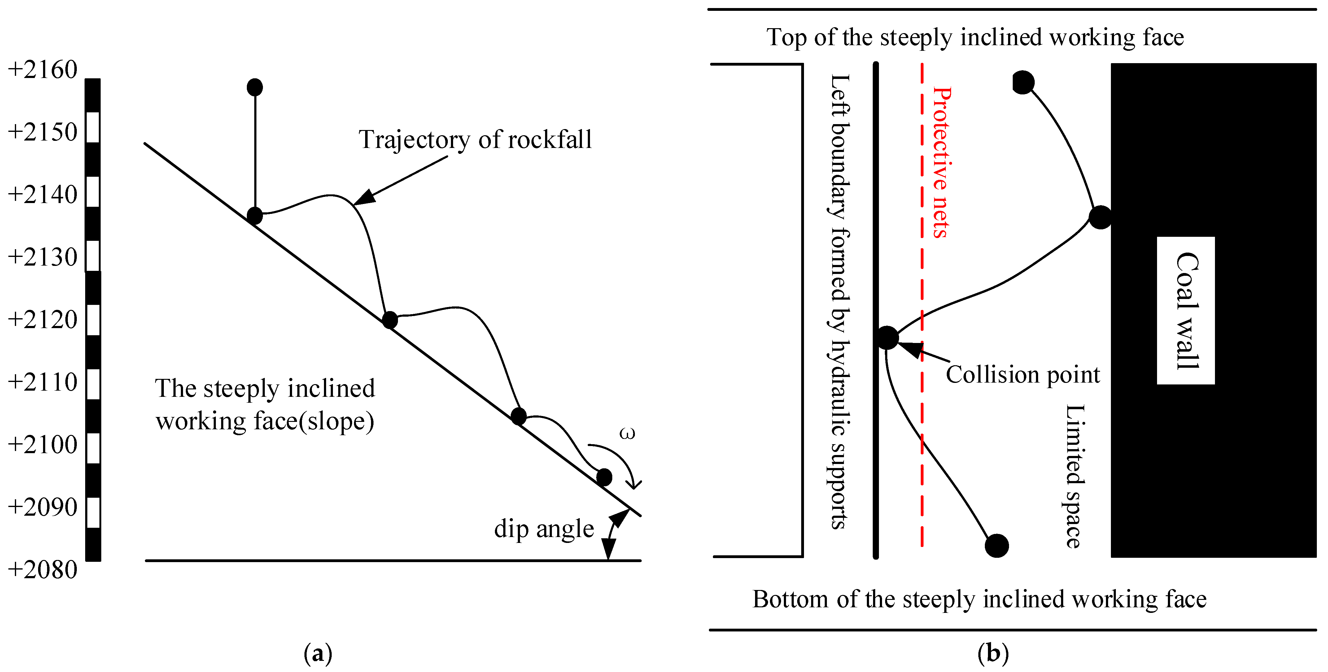
2. Rockfall Separation Mechanism

Coal wall spalling is an important source of random separation blocks, and its counts can reflect the number of random separation blocks [18,19]. In order to study the characteristics of block separation in the initial failure stage of coal wall, a nine-month information collection of coal wall spalling was carried out in a steeply inclined working face from October 2012 to July 2013, the statistical results are shown in Figure 3 and Table 1, the red mark in the diagram indicates that the coal wall spalling occurs at the corresponding numbered support at this time node.
Through the analysis of the working resistance of the support in the lower part (#1~#21), the middle part (#22~#42), and the upper part (#43~#62) of the inclined direction of the working face, it can be seen that the event B mainly occurs in the middle part of the inclined direction of the working face, followed by the upper and lower parts of the inclined direction of the working face. Event C occurs in the lower part of the working face, as well as the intersection area between the middle and the lower part. Through comprehensive analysis of Figure 3 and Table 1, it can be concluded that the coal wall spalling has the following characteristics: First, there are differences in the number of randomly separated blocks in different regions of the steeply dipping coal seam stope. In the inclined direction of the working face, the random separation block in the middle area accounts for 58.3% of the total block, followed by the upper area of the working face (23.3%) and the lower area (18.4%). The distribution characteristics of event B and event A are the same. The frequency of event C in the upper, middle, and lower parts of the working face is 17.0%, 36.2%, and 46.8%, respectively. It can be seen that the closer to the lower part of the inclined direction of the working face, the greater the probability that the support load is less than 1000 kN, and the number of randomly separated blocks is relatively small. Secondly, the stress of the coal wall is closely related to the number of randomly separated blocks. The probability P1 of simultaneous occurrence of event B and event A in the upper, middle, and lower parts of the working face is 64.3%, 49.2%, and 62.5%, respectively. In contrast, the correlation between event C and event A was small, and the probability P2 of simultaneous occurrence in the upper, middle, and lower parts of the working face was 25.0%, 61.8%, and 20.5%, respectively.

3. Particle Flow Method and Hertz Contact Theory

3.1. Particle Flow Code (PFC)

PFC, also known as particle flow theory, is a micro-computer program based on particle flow theory that was proposed by Professor Peter Cundall [20]. It can effectively solve complex micro-structure control problems, and it has good accuracy and stability. Therefore, this study used PFC3D software to simulate the migration process of a rockfall in the SDCS. In the whole analysis process, based on the force–displacement law and Newton’s second law, the contact force of the contacted part is updated through the force–displacement law. Through Newton’s second law, the position of the particles and the wall is updated, and the contact relationship between the particles is readjusted. The two alternates, iterate and traverse the entire particle set at a time step until the equilibrium state is destroyed and the stable state cannot be maintained. The mechanical model is shown in Figure 4, and the calculation process is shown in Figure 5.
In Figure 4, x i [ A ] and x i [ B ] represent the location of the center of the adjacent particles A and B, respectively; d is the distance between particle A and particle B; U n is the overlap between particles; R [ A ] and R [ B ] are the radius of particles A and B, respectively; n i is the unit normal vector of the contact plane between two contacting particles; R [ δ ] is the radius of particle δ ; x i [ c ] is the contact point position.
The two most basic elements in the particle flow model are the particle element and the wall element. The particle element is the element that constitutes the material medium. The wall element is the element used to generate the model boundary. The boundary condition of the force cannot be directly applied to the wall element, and the boundary condition of the displacement and force of the particle set can only be indirectly achieved by applying the velocity.
Using the external particle import generation method and starting from a random point in the particle filling range, the particles are gradually filled around the center. Assuming that a dense disc particle system is constructed in a plane area, it is envisaged to gradually expand and fill the entire area from one point and to refill the model boundary and pores to increase the model density. After building the model, firstly, by introducing geometric figures, the complex entities are constructed by establishing solid grids to construct a surface wall model, and then the complex geometric figures are divided into multiple regions through a continuous numerical model, and then each region is given different attributes to simulate the system response under external forces.

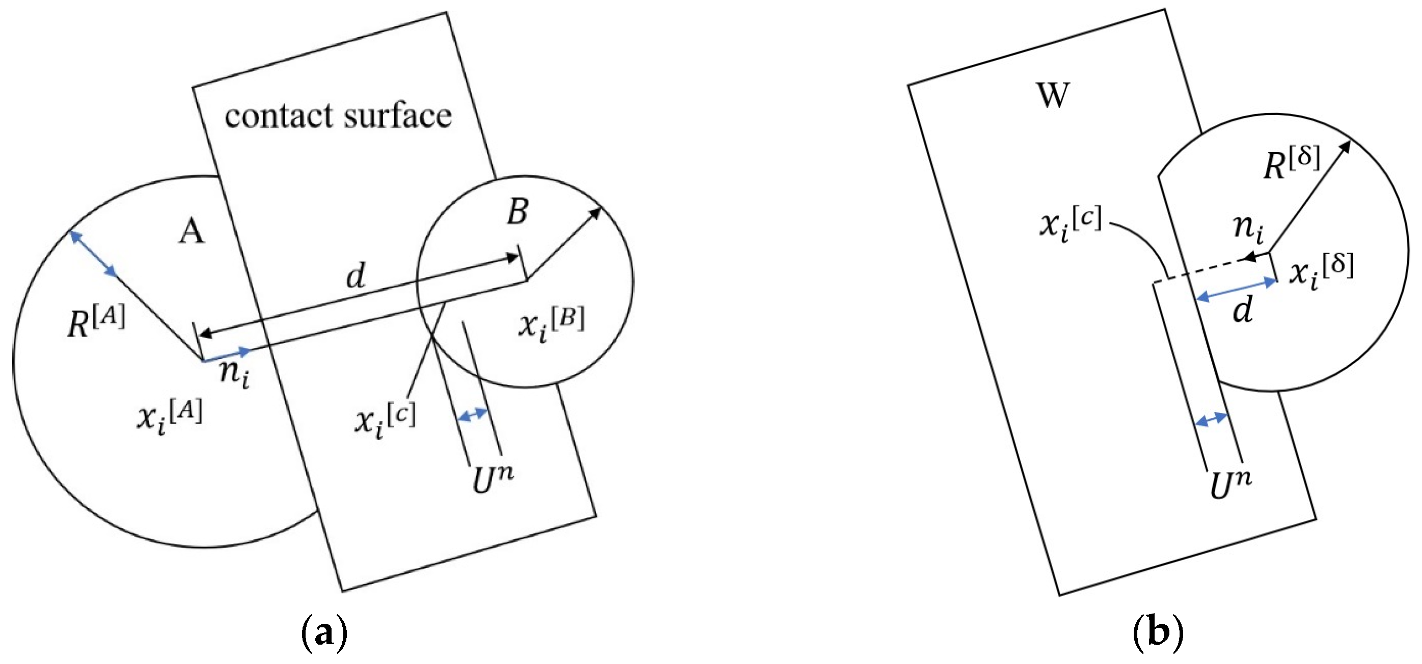
3.2. Hertz Contact Theory

Through simulation using PFC3D software, the rockfall moves to the lower end of the working face and collides with the hydraulic support column. This study modeled the most dangerous situation, that is, the rockfall collides with the midpoint of the column [21].
The process of the collision between the hexahedral rockfall and hydraulic support column is simplified to the Hertz contact model shown in Figure 6. According to the Hertz contact theory, when a cylinder is in elastic contact with a plane, its contact area can be simplified as a rectangle with length L and width 2 a .
The contact stress p is distributed in a semi-elliptical cylinder, and its value is
p ( x ) = 2 F π a 2 L a 2 x 2
where x is the radial distance between the contact point and the contact center and F is the external load. When x = 0 , i.e., the central part of the contact area receives the maximum contact stress, the formula of the maximum contact stress is
P 0 = 2 F π a L = F E * π R L
where E * is the equivalent elastic modulus; E * = E / ( 1 ν 2 ) ; E is the elastic modulus; ν is Poisson’s ratio; and R is the radius of the cylinder.
According to the law of conservation of energy, when the rockfall with a mass m collides with the column at a certain normal velocity v , if the collision system is in a completely elastic state during the whole collision process, the following formula can be obtained [22,23]:
1 2 m v 2 = 0 δ max P ( δ ) d δ
The formula of maximum displacement and maximum impact force of the vertical collision between the hexahedral rockfall and the hydraulic support column is obtained by combining the two formulas:
δ max = e 1 2 ( 1 + p r o d u c t l o g [ e 2 m R 2 v 2 e E * L 5 π ] ) L 2 ( 1 + p r o d u c t l o g [ e 2 m R 2 v 2 e E * L 5 π ] ) 2 R
P max = e 1 + p r o d u c t l o g [ 1 2 e 1 2 ( 1 + p r o d u c t l o g [ e 2 m R 2 v 2 e E * L 5 π ] ) ] ( 1 + p r o d u c t l o g [ e 2 m R 2 v 2 e E * L 5 π ] ) R
where the p r o d u c t l o g function is the inverse function in the interval [−1/e, +∞].

4. Energy Formula

From the boundary conditions of the column, it can be seen that the column is a fixed beam at both ends, the mechanical model of rockfall impact on the midpoint of the hydraulic support column is shown in Figure 7. When rockfall impacts the hydraulic support column, kinetic energy T , potential energy U , and external virtual work W occur on the surface of the column. The final energy calculation formula can be obtained through the Hamiltonian principle and first-order Galerkin discretization.
(1)
Kinetic energy formula
s represents the distance between the root to the reference point before deformation, and the geometric displacement after deformation is described by the orthogonal curve coordinate system ( ξ , η , ζ ) . Before deformation, the displacement r at the reference point P ( s ) is given as follows:
r = s i + ζ ( s ) K
where i and K are unit vectors along the x and z axes, respectively. The amount of deformation Δ is shown below:
Δ = ( u 0 ( s , t ) ζ ( s ) w 0 ( s , t ) s ) i + w 0 ( s , t ) k
where u 0 ( s , t ) and w 0 ( s , t ) are the deformation of the reference point of the neutral axis of the column along the x and z axes, respectively. After deformation, the displacement R at the reference point is given as follows:
R = r + Δ = ( s + u 0 ( s , t ) ζ ( s ) w 0 ( s , t ) s ) i + ( ζ ( s ) + w 0 ( s , t ) ) k
Finally, the kinetic energy formula T is obtained [24], as follows:
T = 0 V 1 2 ρ V ( d R d t ) 2 d V = 1 2 ( 1 4 π D 1 2 1 4 π D 2 2 ) ( 0 l ρ d R d t d R d t d s )
where V , ρ , D 1 , D 2 and l are the volume, density, outer diameter, inner diameter, and length of the column structure, respectively.
(2)
Potential energy calculation
The potential energy U can be given as follows:
U = 0 V Q 11 ( ε 11 ) 2 d V = 1 2 ( 1 4 π D 1 2 ) ( 0 l Q 11 ε 11 ε 11 d s )
where Q 11 is the elastic coefficient along the x axis. ε 11 is the strain of the column along the x axis. In the potential energy expression, the dimensional unit of Q 11 is equivalent to the elastic modulus E , but E is the tensile elastic modulus of the real material, namely the real steel material forming the cylindrical shell; Q 11 is the cylindrical shell according to the outer diameter, but for an equivalent solid cylinder, it becomes the elastic modulus of the solid cylinder. For the convenience of solving the equivalent moment of inertia and the equivalent moment of inertia of the equivalent solid cylinder, the material parameters of the real material of the cylindrical shell are not used in the calculation of potential energy, and Q 11 is also used as the equivalent elastic modulus [25].
(3)
External force virtual work
Based on Hamilton’s principle, kinetic energy, potential energy, and external virtual work are introduced to obtain the following relationship:
t 1 t 2 δ ( T U ) d t + t 1 t 2 δ W d t = 0
The virtual work of the external force by the damping force W can been simplified as
W = t 1 t 2 [ 0 l c d a m p i n g ( d w 0 ( s , t ) d t ) d s ] ( d w 0 ( s , t ) d t ) d t
where the damping coefficient c d a m p i n g is 1.
(4)
Differential equations of motion
The corresponding equations δ u 0 ( s , t ) and δ w 0 ( s , t ) are as follows:
m d 2 u 0 ( s , t ) d t 2 + Q 11 A 2 u 0 ( s , t ) s 2 = 0
m d 2 w 0 ( s , t ) d t 2 + J 0 d 2 d t 2 ( 2 w 0 ( s , t ) s 2 ) Q 11 I 4 w 0 ( s , t ) s 4 c d a m p i n g ( d w 0 ( s , t ) d t ) = 0
where m , A , J 0 and I are the linear density, cross-section area, rotational inertia, and cross-section moment of inertia of the beam, respectively.
(5)
Galerkin discretization
Based on the boundary conditions of fixed beams at both ends, w 0 ( s , t ) can be written as
w 0 ( s , t ) = i = 1 n φ i ( s ) w i ( t )
where φ i ( s ) can be written as
φ i ( s ) = cosh ( λ i s l ) cos ( λ i s l ) [ cosh ( λ i ) cos ( λ i ) sinh ( λ i ) sin ( λ i ) ] ( sinh ( λ i s l ) sin ( λ i s l ) )
where λ i = ( 2 i + 1 ) π / 2 .
When n = 1 , λ 1 4.710 can be obtained; when the first-order Galerkin dispersion is carried out, the governing equation can be obtained as follows:
d 2 w 1 ( t ) d t 2 = 1.000008614 c d a m p i n g d w 1 ( t ) d t l 500.5509646 Q 11 I 1 l 3 1.000008614 m l + 12.30251267 J 0 1 l
The above equation is the energy formula of the collision process between the rockfall and the hydraulic support column.
The midpoint of the column at the initial moment satisfies the following formula:
w 0 ( 0.5 l , 0 ) = δ max = φ 1 ( 0.5 l ) w 1 ( 0 ) = 1.588 | φ 1 ( 0.5 l ) w 1 ( 0 )
The above is the dynamic formula derivation process of the collision process between the rockfall and hydraulic support column.

5. Numerical Simulation

5.1. PFC3D Software to Simulate the Process of Rockfall Migration

The parameters of this study were selected by referring to the geological conditions of the 25,221 working face of the Aiweiergou 2130 coal mine in Urumqi, Xinjiang, China. Figure 8 is the horizontal projection of the contour line of the coal seam floor. From the contour information in Figure 8, it was calculated that the color part is a SDCS. The region was captured to establish a 3D model of the working face floor, as shown in Figure 9.
The property parameters of the regular hexahedral rockfall and the working face are shown in Table 2 and Table 3 [15]. The ETM method is widely used to simulate rockfall migration on the ground slope and rockfall migration in underground SDCSs [16,17,26,27,28,29,30]. Therefore, this study used ETM to verify the accuracy of the simulation results from the PFC3D software. The coal rock in the upper part of the working face was disturbed and coal wall spalling occurred. After separating from the coal wall, the rockfall was formed, and the free fall movement was carried out from the height of 3.27 m. The rockfall collided with the working face floor after free-falling body movement, and the continuous collision movement was carried out along the working face after the collision. The trajectories simulated by the ETM method were compared, as shown in Figure 10. It can be seen that the rockfall migration trajectories obtained by the two methods were basically the same.

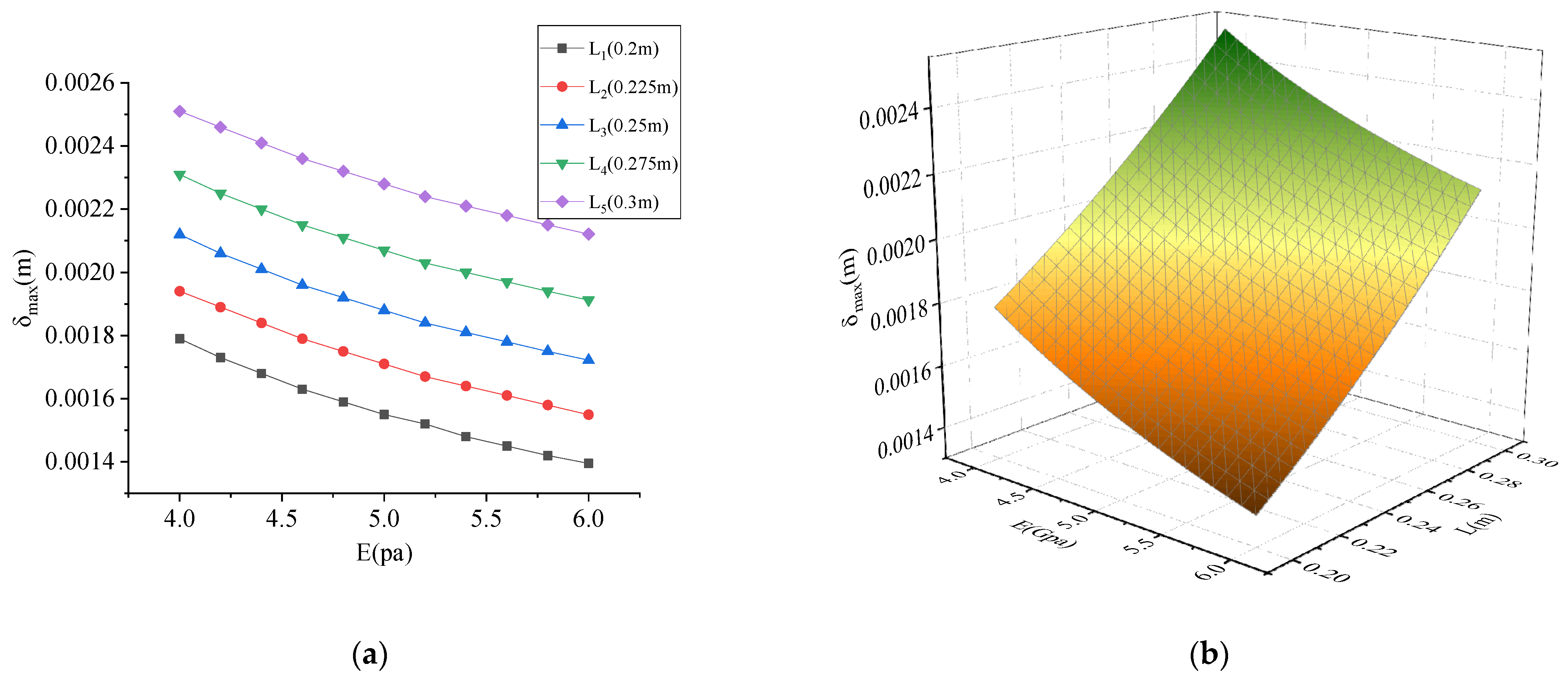
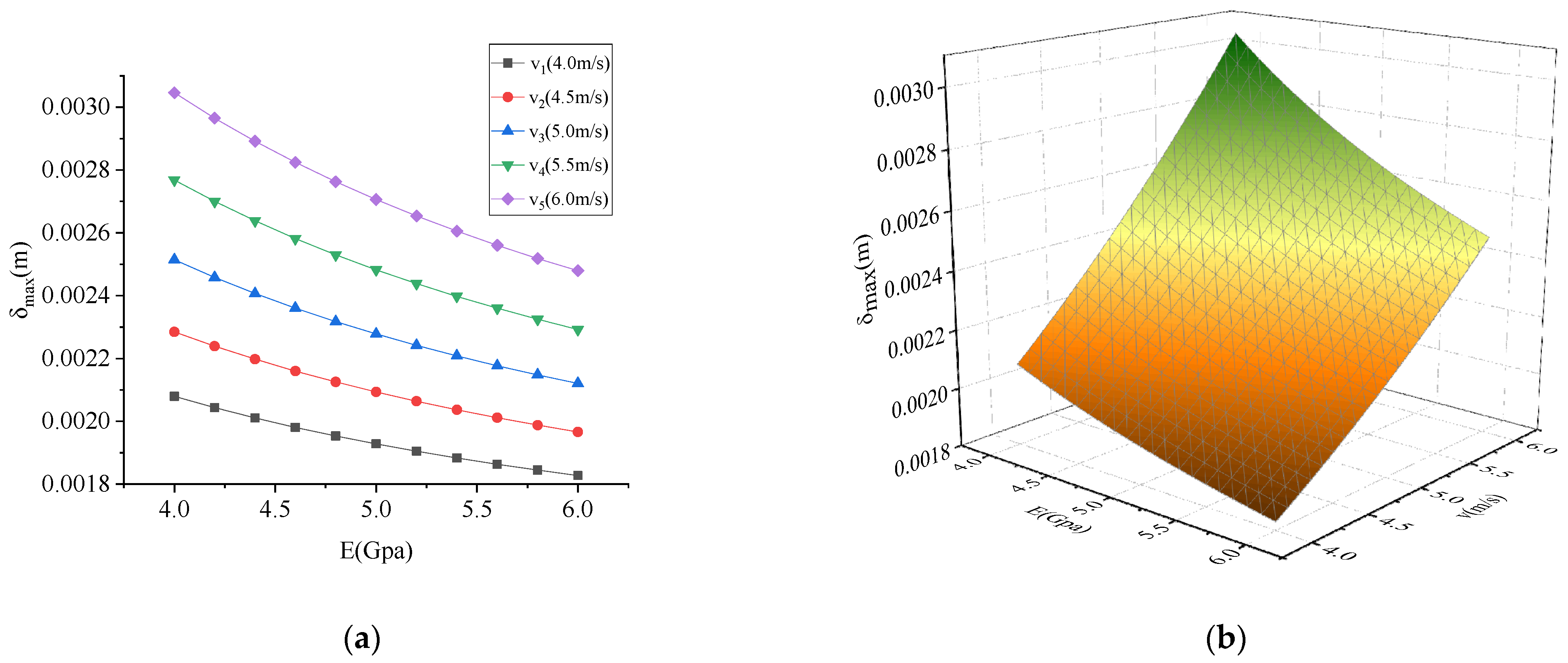
5.2. The Maximum Contact Deformation of the Collision Process between Rockfall and Hydraulic Support Column

In order to meet the anti-eccentric load capacity and structural distortion under a large inclination angle, the ZZ6500/22/48 hydraulic shield support was selected for modeling [31]. The material of the top beam, shield beam, and tail beam of the support was 16 Mn steel. The elastic modulus of the column was 208 GPa, the density was 7850 kg/m3, and the Poisson’s ratio was 0.3. The parameters of the column are shown in Table 4. Taking the migration process of rockfall simulated by the above PFC software as an example, when the rockfall moved to the lower end of the working face and collided with the midpoint of the hydraulic support column, the mechanical model diagram is shown in Figure 7. Using the dynamic equation of this paper, the wave diagram of the midpoint of the column is shown in Figure 11. From Figure 11, it can be seen that the column stops vibrating when it is close to 0.6 s after being impacted by rockfall. In this process, the impact energy of rockfall was partially converted into the potential energy of column deformation, and then the potential energy was partially converted into the kinetic energy of column vibration, and finally, the vibration was stopped under the action of damping [24].
In order to study the influence of rockfall parameters on the impact process, the parameters of rockfall are taken as the following interval values: The relevant parameters of the rockfall are rockfall velocity v (4–6 m/s), rockfall side length L (0.2–0.3 m), rockfall elastic modulus E (4–6 Gpa), rockfall density ρ (2000–3000 kg/m3). The upper and lower ratios of the above parameters are the same, and the upper and lower ratios are 150%. The maximum deformation δ max , maximum impact force P max , column absorption energy W , and energy ratio of the collision process between the hexahedral rockfall and hydraulic support column can be obtained from the numerical simulation [32,33,34,35,36,37].
The maximum deformation of the collision under different parameters is shown in Figure 12, Figure 13 and Figure 14. As shown in Figure 12, Figure 13 and Figure 14, the maximum contact deformation of rockfall was proportional to density ρ , side length L , and velocity v , and inversely proportional to the elastic modulus E . It can be seen from Figure 12 that the influence of elastic modulus E on the maximum contact deformation of rockfall was relatively small compared with the density ρ . Comparing Figure 12 and Figure 13, it can be seen that the influence of side length L on the maximum contact deformation of rockfall was greater than that of density ρ . Comparing Figure 13 and Figure 14, it can be seen that the velocity v has a greater influence on the maximum contact deformation of rockfall than the side length L . Therefore, the order of influence degree was v > L > ρ > E .

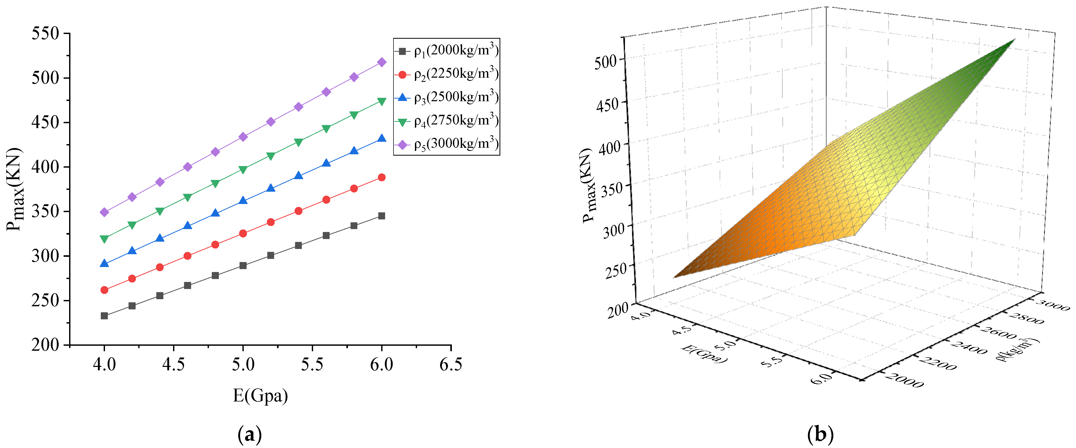
5.3. The Maximum Impact Force of the Collision Process between Rockfall and Hydraulic Support Column

The maximum impact force of the collision under different parameters is shown in Figure 15, Figure 16 and Figure 17. As shown in Figure 15, Figure 16 and Figure 17, the maximum impact force was proportional to density ρ , side length L , velocity v , and elastic modulus E . It can be seen from Figure 15 that the influence of elastic modulus E on the maximum impact force was relatively small compared with the density ρ . Comparing Figure 15 and Figure 17, it can be seen that the influence of velocity v on the maximum impact force was greater than that of density ρ . Comparing Figure 16 and Figure 17, it can be seen that the side length L has a greater influence on the maximum impact force than the velocity v . Therefore, the order of influence degree was L > v > ρ > E .

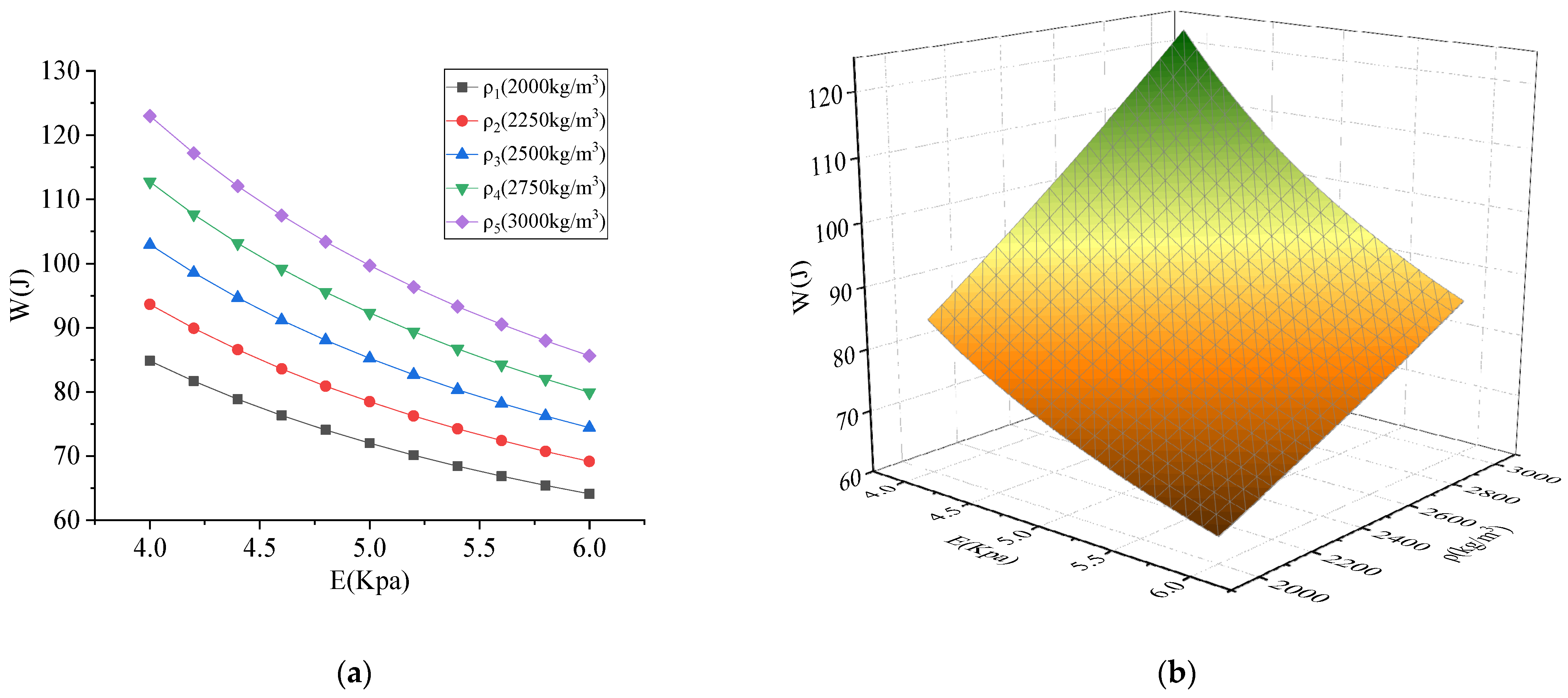
5.4. Absorbed Energy of the Collision Process between Rockfall and Hydraulic Support Column

The absorbed energy is shown in Figure 18, Figure 19 and Figure 20. As shown in Figure 18, Figure 19 and Figure 20, the absorbed energy was proportional to density ρ , side length L , and velocity v , and inversely proportional to the elastic modulus E . It can be seen from Figure 18 that the influence of elastic modulus E on the absorbed energy was relatively small compared with the density ρ . Comparing Figure 18 and Figure 19, it can be seen that the influence of side length L on the absorbed energy was greater than that of density ρ . Comparing Figure 19 and Figure 20, it can be seen that the velocity v has a greater influence on the absorbed energy than the side length L . Therefore, the order of influence degree was v > L > ρ > E .

5.5. Energy Distribution of the Collision Process between Rockfall and Hydraulic Support Column

The proportion of the total energy absorbed by the column from the collision process between the rockfall and hydraulic support column was analyzed. The effect of the parameters on the energy absorption of the column from the hexahedron rockfall was shown in Figure 21.
The four parameters used the ratio of their minimum value to their maximum value as the independent variable. The ratio of the energy absorbed by the column to the total energy was the dependent variable. It can be seen from Figure 21 that when the ratio between the parameter and its maximum value increased, the energy proportion decreased accordingly, and the slope of the curve became gentler and gentler. The energy proportion of the rockfall side length L was higher than that of the other parameters throughout the whole range of values. The curves of density ρ and velocity v were very similar. When the curves reached the endpoint, there was little difference between the values of side length L , density ρ , and velocity v , which were much higher than the value of elastic modulus E . The three curves of elasticity modulus E , velocity v , and density ρ intersected at the same point with coordinates of (0.833, 0.101). When the coordinate interval was (0.667, 0.833), the order of energy proportion was as follows: L > E > v > ρ . When the coordinate interval was (0.833, 1), the energy proportion was roughly sorted as follows: L > ρ > v > E . The energy proportion sorting table is shown in Table 5.

6. Conclusions

(1)
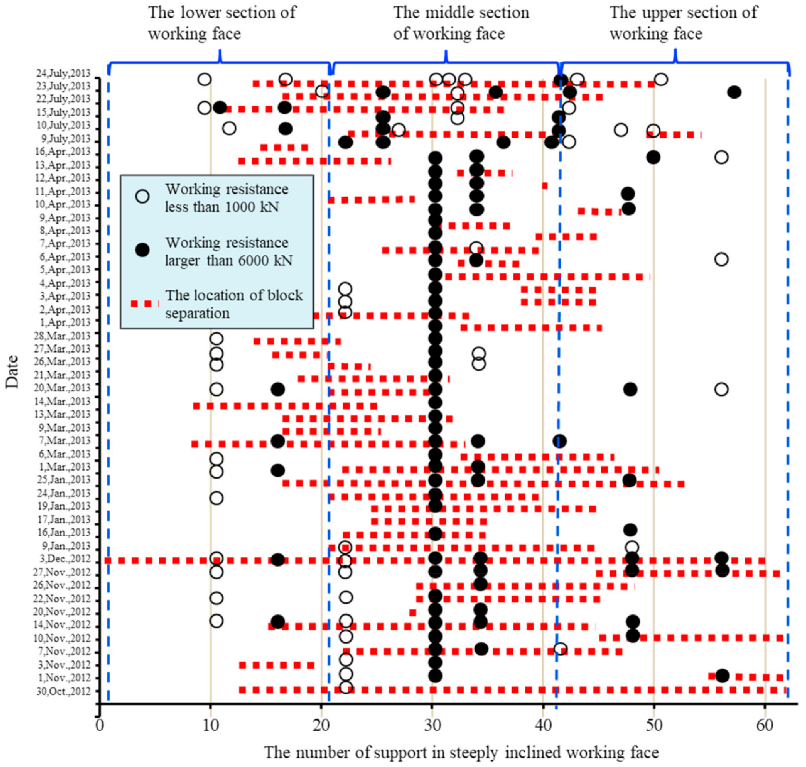
Through the statistical analysis of the measured random separation in the working face, it can be seen that the mechanical state of the coal wall in the upper and lower parts of the inclined direction of the working face has a strong correlation with the number of randomly separated blocks, and the stress state of the coal wall in the middle has a weak correlation with the number of randomly separated blocks. According to the location of rockfall formation and the characteristics of rockfall trajectory, the principle of rockfall control can be determined as follows: the upper rockfall focuses on trajectory blocking, the middle rockfall emphasizes source control, and the lower rockfall prevents secondary disasters. The lower part of the working face is the core area of rockfall prevention and control, and the protection level should be strengthened.
(2)
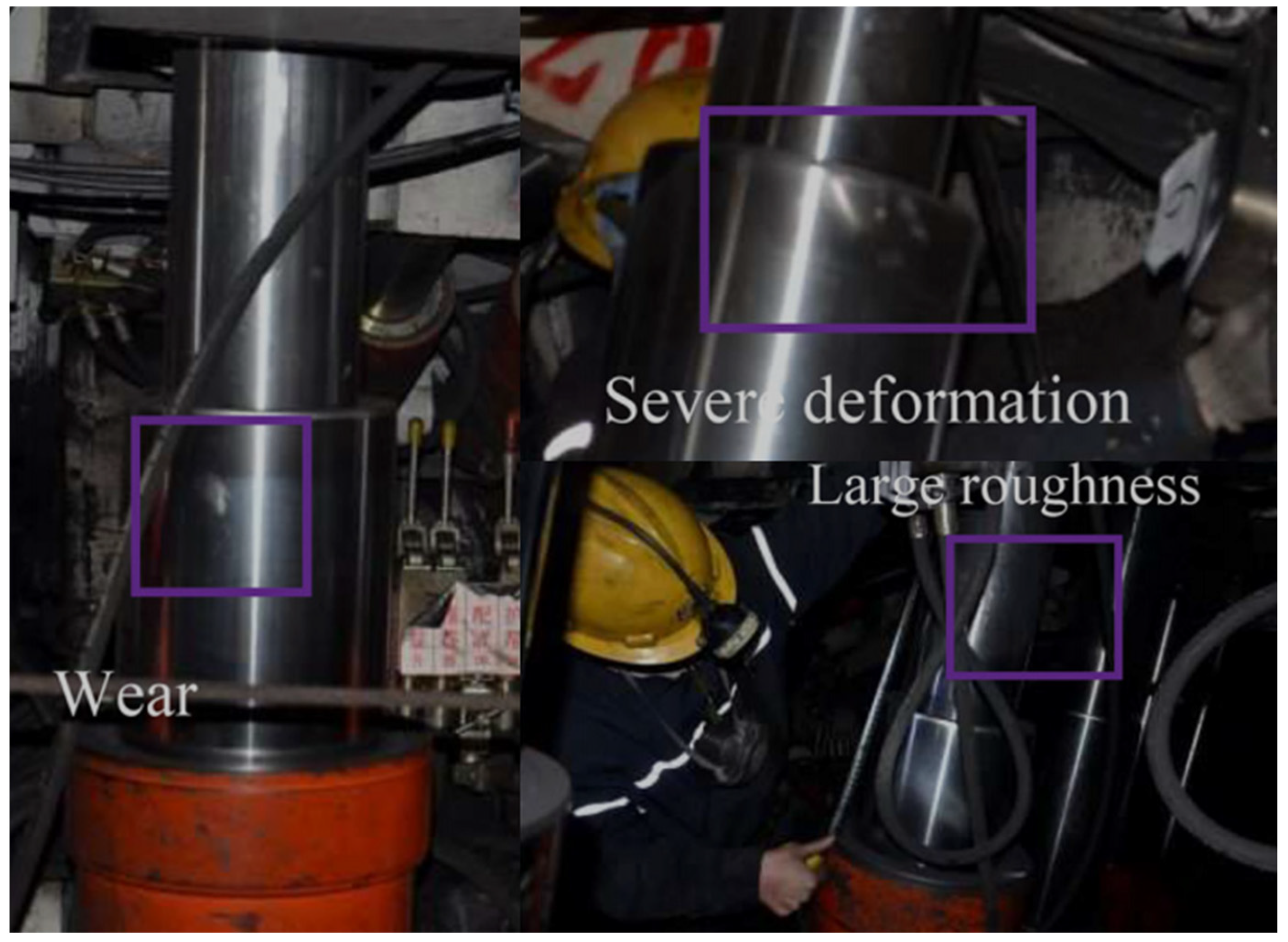
Through the field measurements and statistics of the damage to key equipment in the working face, it was found that the frequency of damage to the hydraulic support column was higher. Therefore, a contact model which can describe the collision process between a polyhedron rockfall and hydraulic support column was constructed in this paper, and the maximum deformation and maximum impact force of the collision can be obtained. The results show that the rockfall velocity and block degree of rockfall have the greatest influence on the maximum deformation and maximum impact force.
(3)
In order to provide safer measures to protect against rockfall disasters, this study modeled the most dangerous situation, i.e., the maximum contact deformation between the rockfall and the column was inflicted on the column. Therefore, this study innovatively assigned the maximum contact deformation between the rockfall and the column to the initial displacement in the dynamic equation of the column, and the evolution law of the energy absorbed by the column was studied when the rockfall impacts the column. The results show that the rockfall velocity and block degree of rockfall have the greatest influence on the energy absorption and maximum impact force of rockfall. Measures should be taken to reduce the impact velocity of rockfall and prevent the occurrence of large-bulk rockfall in SDCSs.
(4)
An accurate description of the rockfall migration characteristics and energy dissipation process in the process of rockfall impact forms the basis for the design of rockfall protection devices. In practice, protection design can be carried out according to the impact position of the rockfall and the energy dissipation characteristics in the process of rockfall impact. The research results of this paper can provide a theoretical basis for the placement of rockfall protection devices and the design of protection device materials.

Author Contributions

Conceptualization, methodology, writing, M.L.; writing—reviewing and editing, resources, B.L.; writing—reviewing and editing and funding acquisition, Y.X. All authors have read and agreed to the published version of the manuscript.

Funding

This work was supported by the Open Fund of the State Key Laboratory of Green and Low-carbon Development of Tar-rich Coal in Western China, Xi’an University of Science and Technology (Grant No. SKLCRKF21-03), Natural Science Basic Research Program of Shaanxi (Program No. 2023-JC-YB-439), FuShun Revitalization Talents Program (Grant No. FSYC202107004), and National Natural Science Foundation of China (Grant Nos. 51974226, 52174127).

Data Availability Statement

The data used to support the findings of this study are available from the corresponding author upon request.

Conflicts of Interest

The authors declare no conflict of interest.

References

  1. Cichowicz, A. Analysis of rockburst and rockfall accidents in relation to class of stope support, regional support, energy of seismic events and mining layout. Atherosclerosis 1994, 143, 99–104. [Google Scholar]
  2. Giacomini, A.; Thoeni, K.; Santise, M.; Diotri, F.; Booth, S.; Fityus, S.; Roncella, R. Temporal-spatial frequency rockfall data from open-pit highwalls using a low-cost monitoring system. Remote Sens. 2020, 12, 2459. [Google Scholar] [CrossRef]
  3. Ferrari, F.; Giacomini, A.; Thoeni, K.; Lambert, C. Qualitative evolving rockfall hazard assessment for highwalls. Int. J. Rock Mech. Min. Sci. 2017, 98, 88–101. [Google Scholar] [CrossRef]
  4. Zheng, D.; Frost, J.D.; Huang, R.D.; Liu, F.Z. Failure process and modes of rockfall induced by underground mining: A case study of Kaiyang Phosphorite Mine rockfalls. Eng. Geol. 2015, 197, 145–157. [Google Scholar] [CrossRef]
  5. Wu, Y.P.; Yun, D.F.; Xie, P.S.; Wang, H.W.; Lang, D. Progress, practice and scientific issues in steeply dipping seams fully-mechanized mining. J. China Coal Soc. 2020, 45, 24–34. [Google Scholar]
  6. Wu, Y.P.; Liu, K.Z.; Yun, D.F.; Xie, P.S.; Wang, H.W. Research progress on the safe and efficient mining technology of steeply dipping seam. J. China Coal Soc. 2014, 39, 1611–1618. [Google Scholar]
  7. Hu, B.S.; Wu, Y.P.; Wang, H.W.; Tang, Y.P.; Wang, C.R. Risk mitigation for rockfall hazards in steeply dipping seam: A case study in Xinjiang, northwestern China. Geomat. Nat. Hazards Risk 2021, 12, 988–1014. [Google Scholar] [CrossRef]
  8. Tu, H.S.; Tu, S.H.; Yuan, Y.; Wang, F.T.; Bai, Q.S. Present situation of fully mechanized mining technology for steeply inclined coal seams in China. Arab. J. Geosci. 2015, 8, 4485–4494. [Google Scholar] [CrossRef]
  9. Wu, Y.P.; Yun, D.F.; Xie, P.S.; Wang, H.W.; Luo, S.H. Theory and Technology of Fully Mechanized Longwall Mining in Steeply Inclined Seam; Science Press: Beijing, China, 2017. [Google Scholar]
  10. Wu, Y.P.; Hu, B.S.; Xie, P.S.; Li, S.H.; Huangfu, J.Y. Impact damage of flying gangue in steeply dipping seams and its control. J. China Coal Soc. 2018, 43, 2694–2702. [Google Scholar]
  11. Wu, Y.P.; Hu, B.S.; Lang, D.; Tang, Y.P. Risk assessment approach for rockfall hazards in steeply dipping coal seams. Int. J. Rock Mech. Min. Sci. 2021, 138, 104626. [Google Scholar] [CrossRef]
  12. Hu, B.S. Damage mechanism and control of flying-gangue hazard in longwall mining of steeply dipping coal seams. Chin. J. Rock Mech. Eng. 2022, 41, 2592. [Google Scholar]
  13. Wu, Y.P.; Wu, Y.P.; Xie, P.S.; Zeng, Y.F. Flying gangue regional control technology in longwall mining face of steeply dipping seam. Coal Sci. Technol. 2017, 45, 1–5. [Google Scholar]
  14. Liu, M.; Wu, Y.P.; Geng, S.; Duo, Y.L.; Lv, W.Y. Threat level assessment of flying gangue in steep seam mining. J. China Coal Soc. 2020, 45, 3688–3695. [Google Scholar]
  15. Liu, M.; Zhou, Y.T.; Lv, W.Y. Normal characteristic quantity theory of flying gangue motion in steeply dipping seam with stochastic parameters. J. China Coal Soc. 2021, 46, 2237–2244. [Google Scholar]
  16. Liu, M.; Chen, J.; Xiao, Y.; Lv, W.Y. Migration law for random parameters rockfall in steeply dipping coal seams. Front. Earth Sci. 2023, 11, 1088188. [Google Scholar] [CrossRef]
  17. Chen, J. Study on the Migration Law of Flying Gangue in Steeply Dipping Coal Seam Based on Energy Tracking Method; Liaoning Petrochemical University: Fushun, China, 2021. [Google Scholar]
  18. Wang, J.A.; Jiao, J.L. Criteria of support stability in mining of steeply inclined thick coal seam. Int. J. Rock Mech. Min. Sci. 2016, 82, 22–35. [Google Scholar] [CrossRef]
  19. Yao, Q.L.; Li, X.H.; Sun, B.Y.; Ju, M.H.; Chen, T.; Zhou, J.; Liang, S.; Qu, Q.D. Numerical investigation of the effects of coal seam dip angle on coal wall stability. Int. J. Rock Mech. Min. Sci. 2017, 100, 298–309. [Google Scholar] [CrossRef]
  20. Sławomir, B.; Stanisław, P. Numerical study of pressure on dams in a backfilled mining shaft based on PFC3D code. Comput. Geotech. 2015, 66, 230–244. [Google Scholar]
  21. Fu, G.H. An Extension of Hertz’s Theory in Contact Mechanics. J. Appl. Mech. 2006, 74, 373–374. [Google Scholar] [CrossRef]
  22. Margarida, M.; Pedro, M.; Paulo, F. Compliant contact force models in multibody dynamics: Evolution of the Hertz contact theory. Mech. Mach. Theory 2012, 53, 99–121. [Google Scholar]
  23. Zhupanska, O.I. Contact problem for elastic spheres: Applicability of the Hertz theory to non-small contact areas. Int. J. Eng. Sci. 2011, 49, 576–588. [Google Scholar] [CrossRef]
  24. Fu, X.L.; Liao, W.H. Nondimensional model and parametric studies of impact piezoelectric energy harvesting with dissipation. J. Sound Vib. 2018, 429, 78–95. [Google Scholar] [CrossRef]
  25. Chen, S.; Yao, Z.J.; Goldsmith, C.L. A new in situ residual stress measurement method for a MEMS thin fixed-fixed beam structure. J. Microelectromech. Syst. 2002, 11, 309–316. [Google Scholar] [CrossRef]
  26. Xu, J.J.; Tang, X.H.; Liu, Q.S.; Feng, Y.F. Investigation on trajectory of rolling rock affected by rock fragmentation based on energy tracking method. Rock Soil Mech. 2019, 40, 541–548. [Google Scholar]
  27. Paluszny, A.; Tang, X.H.; Zimmerman, R.W. Fracture and impulse based finite-discrete element modelling of fragmentation. Comput. Mech. 2013, 52, 1071–1084. [Google Scholar] [CrossRef]
  28. Tang, X.H.; Paluszny, A.; Zimmerman, R.W. Energy conservative property of impulse-based methods for collision resolution. Int. J. Numer. Methods Eng. 2013, 95, 529–540. [Google Scholar] [CrossRef]
  29. Tang, X.H.; Paluszny, A.; Zimmerman, R.W. An impulse-based energy tracking method for collision resolution. Comput. Methods Appl. Mech. Eng. 2014, 278, 160–185. [Google Scholar] [CrossRef]
  30. Paluszny, A.; Tang, X.H.; Nejati, M.; Zimmerman, R.W. A direct fragmentation method with Weibull function distribution of sizes based on finite- and discrete element simulations. Int. J. Solids Struct. 2016, 80, 38–51. [Google Scholar] [CrossRef]
  31. Xie, P.S.; Zhang, Y.Y.; Zhang, Y.L.; Chen, J.J.; Zhang, X.B.; Duan, J.J. Instability law of the coal-rock interbedded roof and its influence on supports in large mining height working face with steeply dipping coal seam. J. China Coal Soc. 2021, 46, 344–356. [Google Scholar]
  32. Yang, Y.; Zeng, Q.L. Influence analysis of the elastic supporting to the dynamic response when the spherical rock elastic impacting the metal plate and to the coal gangue impact differences. IEEE Access 2019, 7, 143347–143366. [Google Scholar] [CrossRef]
  33. Yang, Y.; Zeng, Q.L.; Wan, L. Dynamic response analysis of the vertical elastic impact of the spherical rock on the metal plate. Int. J. Solids Struct. 2019, 158, 287–302. [Google Scholar] [CrossRef]
  34. Yang, Y.; Zhang, Y.; Zeng, Q.L.; Wan, L.R.; Zhang, Q. Simulation research on impact contact behavior between coal gangue particle and the hydraulic support: Contact response differences induced by the difference in impacted location and impact material. Materials 2022, 15, 3890. [Google Scholar] [CrossRef] [PubMed]
  35. Yang, Y.; Zeng, Q.L.; Wan, L.R. Contact response analysis of vertical impact between elastic sphere and elastic half space. Shock. Vib. 2018, 2018, 1802174. [Google Scholar] [CrossRef]
  36. Yang, Y.; Wan, L.R. Study on the vibroimpact response of the particle elastic impact on the metal plate. Shock. Vib. 2019, 2019, 6325472. [Google Scholar] [CrossRef]
  37. Zeng, Q.L.; Yang, Y.; Zhang, X.; Wan, L.R.; Zhou, J.H.; Yin, G.J. Study on metal plate vibration response under coal–gangue impact based on 3D simulation. Arab. J. Sci. Eng. 2019, 44, 7567–7580. [Google Scholar] [CrossRef]
Figure 1. Schematic diagram of trajectory of rockfall. (a) Trajectory of rockfall along the inclination of working face; (b) Boundaries of the rockfall in underground coal mines.
Processes 11 02497 g001
Figure 2. Rockfall impact damage to hydraulic support column.
Processes 11 02497 g002
Figure 3. Relationship between coal wall spalling and the working resistance of hydraulic support.
Processes 11 02497 g003
Figure 4. Contact theoretical model (a) Two particles contact; (b) Particles contact with the wall.
Processes 11 02497 g004
Figure 5. The schematic diagram of PFC iterative process.
Processes 11 02497 g005
Figure 6. Hertz contact between cylinder and plane: (a) simulated diagram; (b) theoretical diagram.
Processes 11 02497 g006
Figure 7. Mechanical model of rockfall impact on the midpoint of a hydraulic support column.
Processes 11 02497 g007
Figure 8. The contour lines of the working face floor.
Processes 11 02497 g008
Figure 9. 3D model of the working face floor.
Processes 11 02497 g009
Figure 10. Rockfall migration trajectory image contrast diagram.
Processes 11 02497 g010
Figure 11. The wave diagram of the midpoint.
Processes 11 02497 g011
Figure 12. Influence of parameters on maximum deformation for elastic modulus vs. density: (a) two-dimensional graph; (b) three-dimensional graph.
Processes 11 02497 g012
Figure 13. Influence of parameters on maximum deformation for elastic modulus vs. side length: (a) two-dimensional graph; (b) three-dimensional graph.
Processes 11 02497 g013
Figure 14. Influence of parameters on maximum deformation for elastic modulus vs. velocity: (a) two-dimensional graph; (b) three-dimensional graph.
Processes 11 02497 g014
Figure 15. Influence of parameters on maximum impact force for elastic modulus vs. density: (a) two-dimensional graph; (b) three-dimensional graph.
Processes 11 02497 g015
Figure 16. Influence of parameters on maximum impact force for elastic modulus vs. side length: (a) two-dimensional graph; (b) three-dimensional graph.
Processes 11 02497 g016
Figure 17. Influence of parameters on maximum impact force for elastic modulus vs. velocity: (a) two-dimensional graph; (b) three-dimensional graph.
Processes 11 02497 g017
Figure 18. Influence of parameters on energy absorbed by column for elastic modulus vs. density: (a) two-dimensional graph; (b) three-dimensional graph.
Processes 11 02497 g018
Figure 19. Influence of parameters on energy absorbed by column for elastic modulus vs. side length: (a) two-dimensional graph; (b) three-dimensional graph.
Processes 11 02497 g019
Figure 20. Influence of parameters on energy absorbed by column for elastic modulus vs. velocity: (a) two-dimensional graph; (b) three-dimensional graph.
Processes 11 02497 g020
Figure 21. Effect of the parameters on the proportion of energy absorbed by the column from the hexahedron rockfall.
Processes 11 02497 g021
Table 1. Statistics of coal wall spalling and working resistance.
ItemsLower SectionMiddle SectionUpper SectionTotal
Counts of coal wall spalling (A)118375150643
Counts of working resistance greater than 6000 kN (B)8651487
Counts of working resistance less than 1000 kN (C)2217847
A∩B532946
A∩C4.510.5217
P1(A∩B)62.549.264.3
P2(A∩C)20.561.825.0
Table 2. Property parameters of rockfall.
Density
(kg/m3)
Elasticity Modulus (Gpa)Tangential Stiffness (N/m)Normal
Stiffness (N/m)
Poisson’s RatioFriction CoefficientSide
Length (m)
25005110.280.20.3
Table 3. Property parameters of the working face.
Density
(kg/m3)
Dip Angle (°)Internal Friction
Angle (°)
Elasticity Modulus (GPa)Critical DampingWorking Face
Length (m)
280045304.380.35120
Table 4. Hydraulic support column parameters.
Type of Hydraulic CylinderCylinder PositionPiston Diameter (m)Diameter of Piston Rod (m)Oil Cavity Length (m)
Column hydraulic cylinderFirst stage0.2500.2351.310
Second stage0.1800.1601.285
Table 5. Energy proportion sorting table.
X Axis Coordinate IntervalEnergy Proportion Sorting
(0.667, 0.833) L  >  E  >  v  >  ρ
(0.833, 1.000000) L  >  ρ  >  v  >  E
Disclaimer/Publisher’s Note: The statements, opinions and data contained in all publications are solely those of the individual author(s) and contributor(s) and not of MDPI and/or the editor(s). MDPI and/or the editor(s) disclaim responsibility for any injury to people or property resulting from any ideas, methods, instructions or products referred to in the content.

