

Optimization of Carbon Sequestration and Carbon Displacement in Fractured Horizontal Wells in Low Permeability Reservoirs

Abstract
1. Introduction
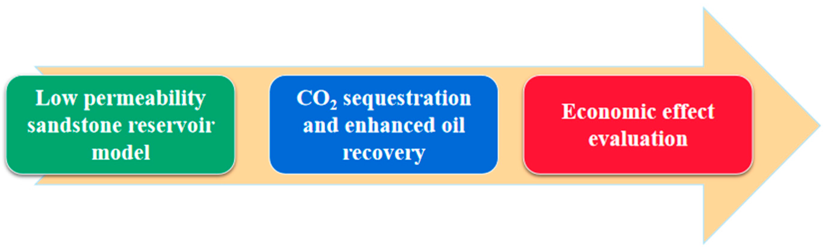
2. Methodology
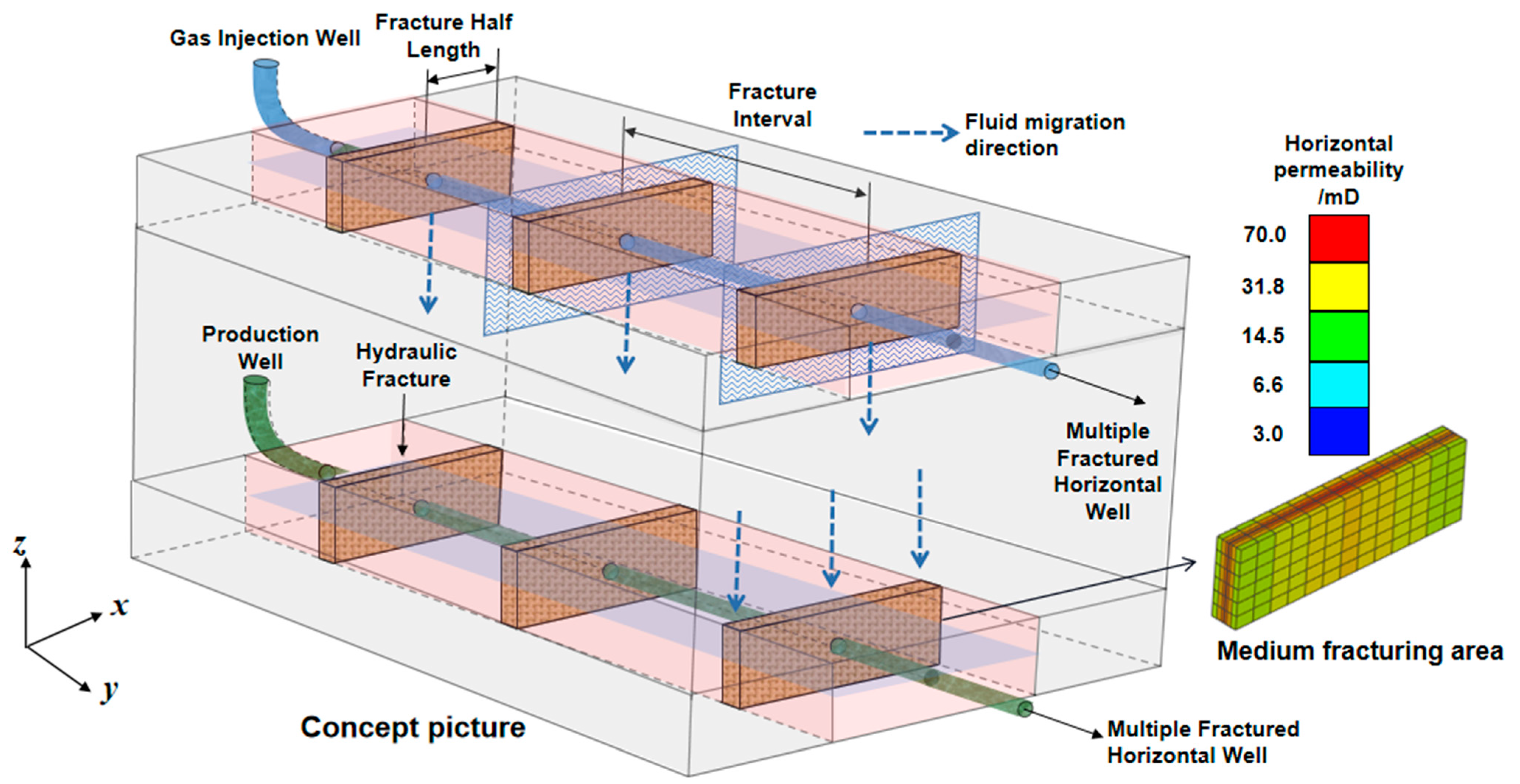
2.1. Establishment of Numerical Simulation Model
2.2. Scheme Design
2.3. Establishment of Objective Function
3. Analysis and Discussion
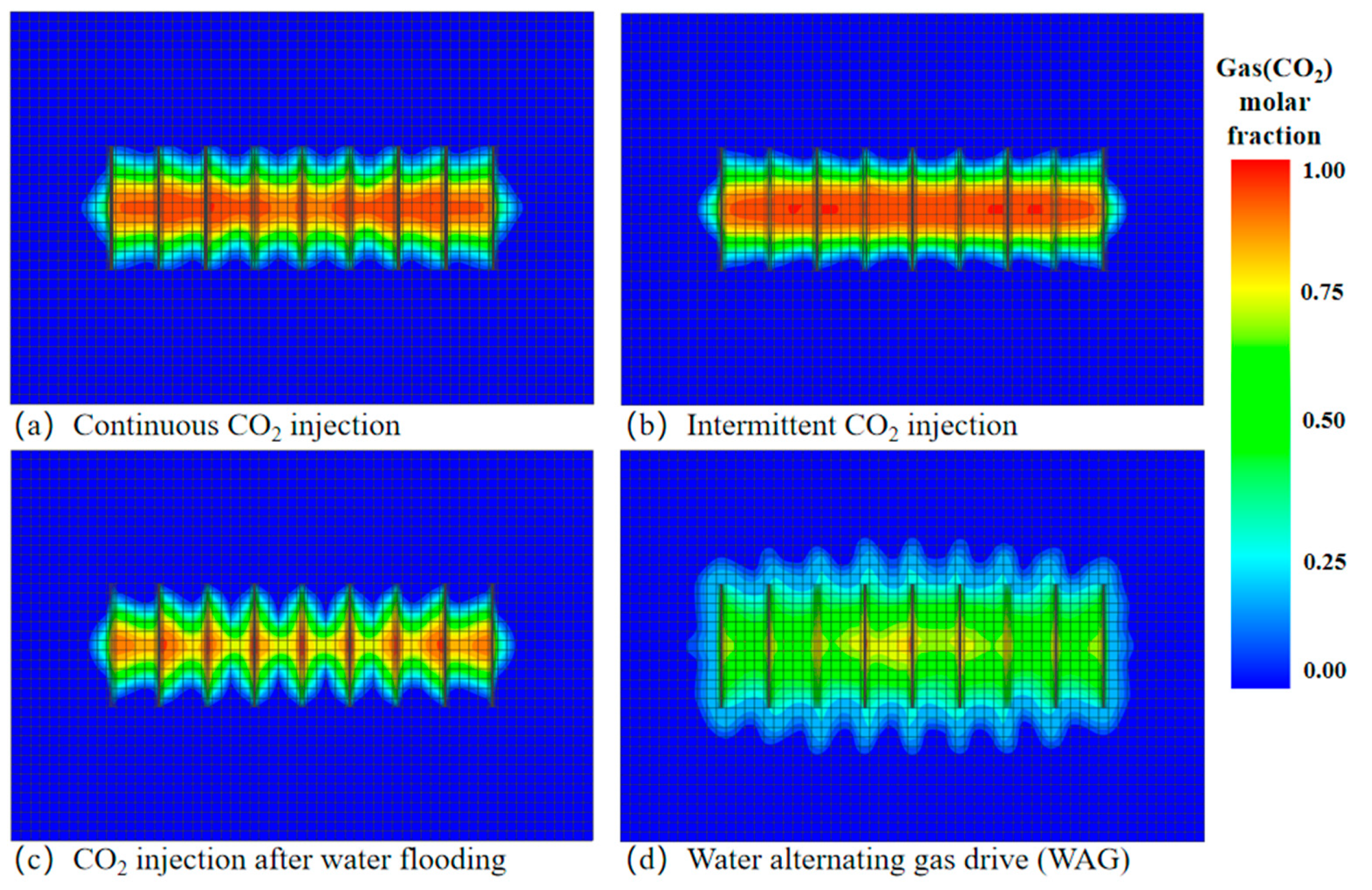
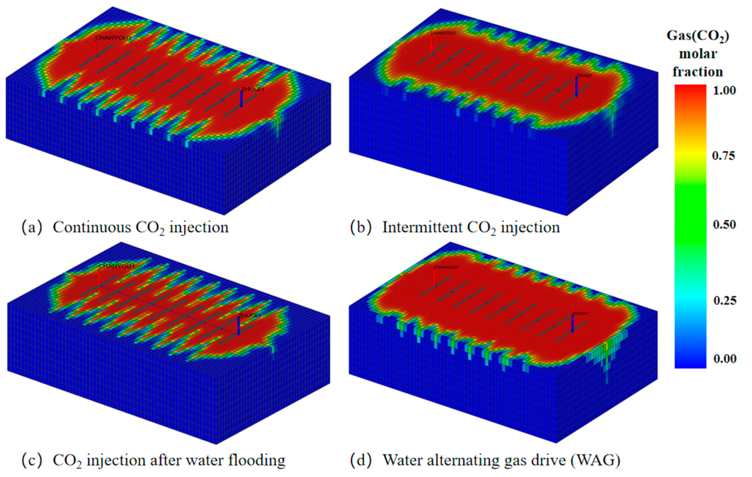
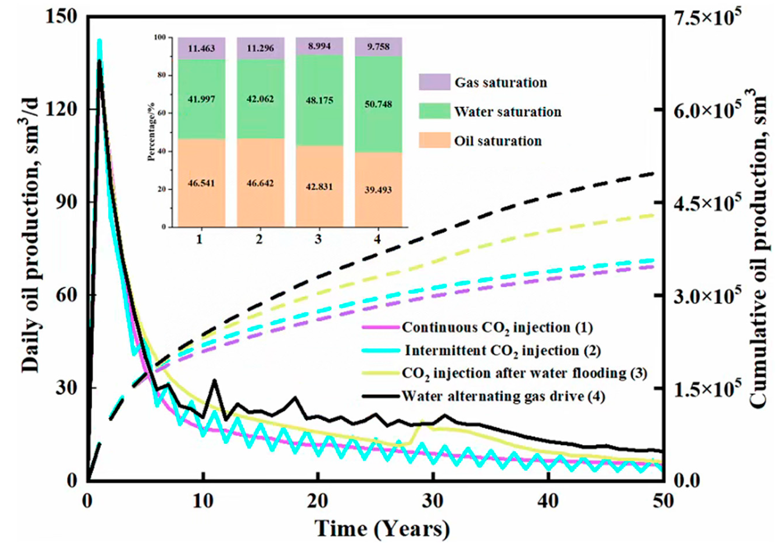
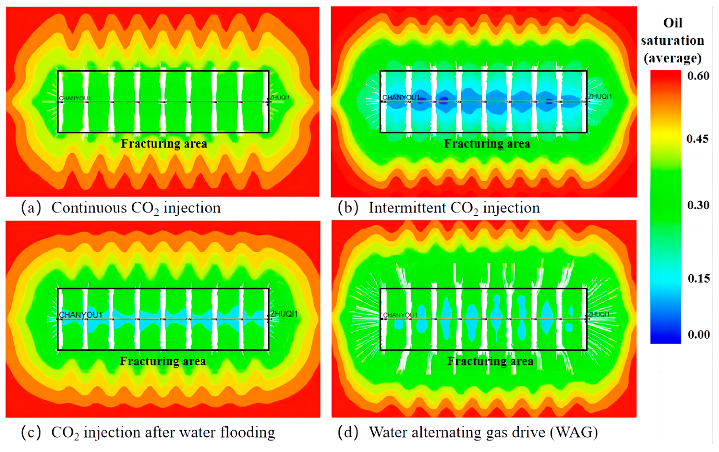
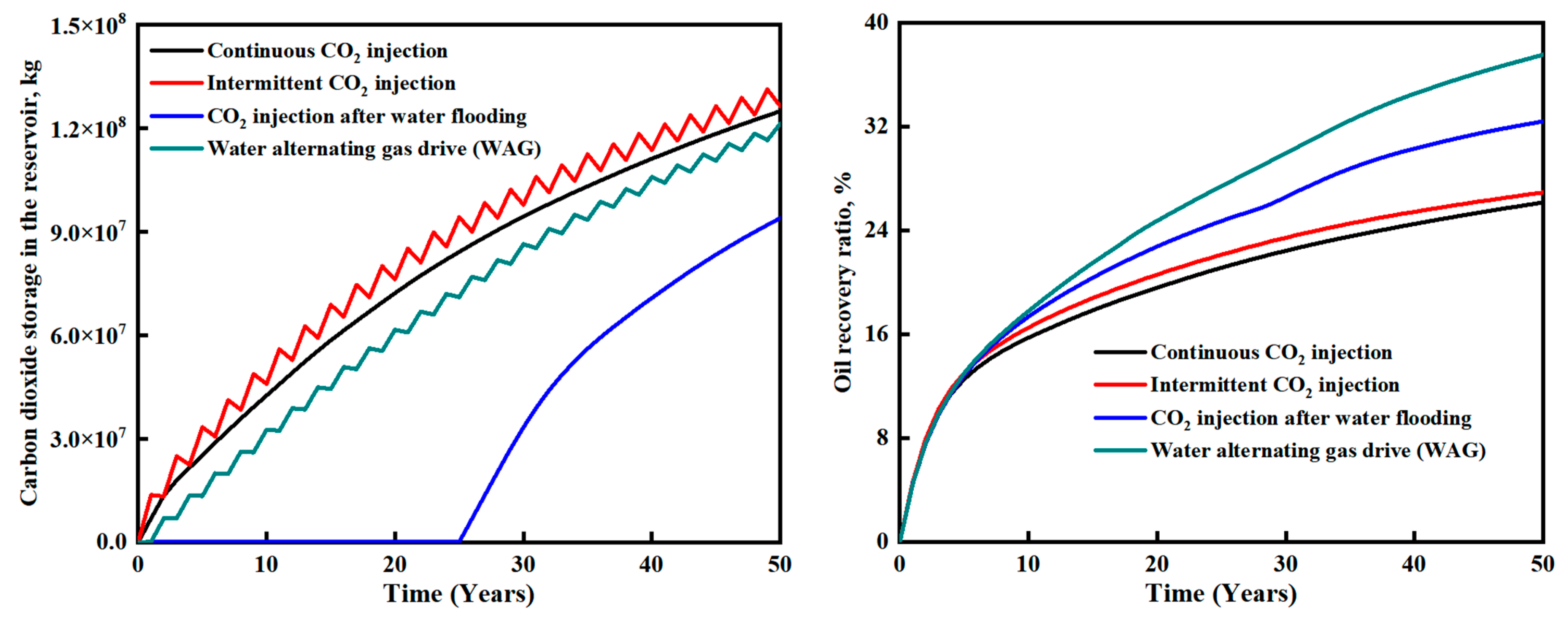
3.1. Effects of Four Cases on CO2 Storage and Oil Displacement
3.2. Economic Analysis
4. Conclusions
Author Contributions
Funding
Data Availability Statement
Conflicts of Interest
References
- Qin, J.; Li, Y.; Wu, D.; Weng, H.; Wang, G. Global progress of CCUS and China’s countermeasures and suggestions. Oil Gas Geol. Recovery 2020, 27, 20–28. [Google Scholar] [CrossRef]
- Nie, H.Y.; Cao, Y.; Liu, D.-Q.; Xi, F.; Wang, D. Challenges and countermeasures to realize the industrial value of CCUS in China. Mod. Chem. Ind. 2023, 43, 11–15. [Google Scholar] [CrossRef]
- Chen, B.; Xiao, H.; Li, J.; Wang, X. Research progress of carbon dioxide capture, utilization and storage. Appl. Chem. Eng. 2018, 47, 589–592. [Google Scholar] [CrossRef]
- Peng, S. Domestic and foreign carbon capture, utilization and storage (CCUS) projects and related policy development. Low Carbon World 2013, 1, 18–21. [Google Scholar]
- Zhong, P.; Peng, S.; Jia, L.; Zhang, J. R&D and demonstration of carbon capture, utilization and storage technology in China. China Popul. Resour. Environ. 2011, 21, 41–45. [Google Scholar]
- Xue-Ting, P.; Hao-Dong, L.; Xian, Z. Interpretation of IPCC AR6 Report: Assessment of Global Carbon Capture, Utilization and Storage (CCUS) Technology Development. Adv. Clim. Chang. Res. 2022, 18, 580. [Google Scholar]
- Li, X. Speeding up the scale development to meet the cost challenge of CCUS. China Petroleum News, 29 March 2022. [Google Scholar] [CrossRef]
- Yuet, C.L. Decoding CCUS-Analysis of the present situation, cost and countermeasures of carbon capture, utilization and storage in China. China Pet. Corp. 2021, 36–37. [Google Scholar]
- Cheng, Q. CCUS of China: Enlarging Scale and Reducing Cost. Sinopec News, 23 August 2021. [Google Scholar] [CrossRef]
- Liu, S.; Chen, S. Policy comparison supporting the development of carbon capture and storage technology (CCUS) and its enlightenment to China. Heilongjiang Financ. 2023, 11, 34–37. [Google Scholar]
- Yang, W. Research on the Cost Analysis of Carbon Capture and Storage (CCUS) Technology Path. Master’s Thesis, Tianjin University of Science and Technology, Tianjin, China, 2020. [Google Scholar] [CrossRef]
- Butl, R.M. A new approach to the modeling of steam assisted gravity drainage. J. Can. Pet. Technol. 1985, 24, 42–51. [Google Scholar] [CrossRef]
- Hagoort, J. Oil recovery by gravity drainage. Soc. Pet. Eng. J. 1980, 20, 139–150. [Google Scholar] [CrossRef]
- Kantzas, A.; Chatzis, I.; Dullien, F.L. Enhanced oil recovery by inert gas injection. In Proceedings of the SPE/DOE 17379, SPE Enhanced Oil Recovery Symposium, Tulsa, OK, USA, 17–20 April 1988. [Google Scholar]
- Norollah, K.; Bashiri, A. Gas-assisted gravity drainage (GAGD) process for improved light oil recovery. In Proceedings of the International Petroleum Technology Conference, Doha, Qatar, 7–9 December 2009. [Google Scholar]
- Naylor, P.; Frørup, M. Gravity-stable nitrogen displacement of oil. In Proceedings of the SPE 19641, SPE Annual Technical Conference and Exhibition, San Antonio, TX, USA, 8–11 October 1989. [Google Scholar]
- Tiwari, S.; Kumar, M.S. Nitrogen injection for simultaneous exploitation of gas cap. In Proceedings of the SPE 68169, SPE Middle East Oil Show, Manama, Bahrain, 17–20 March 2001. [Google Scholar]
- Gao, J.; Yang, S.Y.; Yuan, Y.W. Mechanism and controlling factors of GAGD technology. Geol. Sci. Technol. Inf. 2013, 32, 80–84. [Google Scholar]
- Chen, X.; Li, Y.; Liao, G.; Zhang, C.; Xu, S.; Qi, H.; Tang, X. Gravity stable displacement mechanism of oxygen-reduced air and its relationship with oil recovery. Pet. Explor. Dev. 2020, 47, 780–788. [Google Scholar] [CrossRef]
- Dai, X.; Wang, M.; Wei, C.; Zhang, J.; Wang, X.; Zou, M. Factors affecting shale microscopic pore structure variation during interaction with supercritical CO2. J. CO2 Util. 2019, 38, 194–211. [Google Scholar] [CrossRef]
- Fatah, A.; Mahmud, H.B.; Bennour, Z.; Gholami, R.; Hossain, M. Geochemical modelling of CO2 interactions with shale: Kinetics of mineral dissolution and precipitation on geological time scales. Chem. Geol. 2022, 592, 120742. [Google Scholar] [CrossRef]
- Babanezhad, M.; Taghvaie Nakhjiri, A.; Rezakazemi, M.; Marjani, A.; Shirazian, S. Functional input and membership characteristics in the accuracy of machine learning approach for estimation of multiphase flow. Sci. Rep. 2020, 10, 17793. [Google Scholar] [CrossRef] [PubMed]
- Cardwell, W.T., Jr.; Parsons, R.L. Gravity Drainage Theory. Trans. AIME 1959, 179, 199–215. [Google Scholar] [CrossRef]
- Zhang, L.; Yang, J.; Xiong, Y.; Fu, Q. Optimization evaluation of CO2 storage and oil displacementeffect under different injection and production modes. Nat. Gas Ind. 2008, 102–104+147–148. [Google Scholar]
- Zhang, X. Numerical Simulation Study of CO2 Saline Layer Burying. Master’s Thesis, China University of Petroleum, Beijing, China, 2011. [Google Scholar]
- Rostami, B.; Kharrat, R.; Pooladi-Darvish, M.; Ghotbi, C. Identification of Fluid Dynamics in Forced Gravity Drainage Using Dimensionless Groups. Transp. Porous Media 2010, 83, 725–740. [Google Scholar] [CrossRef]
- Li, B. Study on CO2 Displacement and Burial Effect of Sandstone Reservoir. Master’s Thesis, Yanshan University, Qinhuangdao, China, 2016. [Google Scholar]
- Mi, J.; Ma, X. Analysis of CCUS technology development trend in China. Chin. J. Electr. Eng. 2019, 39, 2537–2544. [Google Scholar] [CrossRef]
- Hu, Y.; Hao, M. Study on the development characteristics and cost limit of CCUS industry. Oil Gas Reserv. Eval. Dev. 2020, 10, 15–22+2. [Google Scholar] [CrossRef]
- Gao, R.; Lu, C.; Lun, Z. Integrated evaluation method of CO2 flooding-storage. Thermalpowergeneration 2021, 50, 115–122. [Google Scholar] [CrossRef]
- Xing, L.; Wu, Z.; Zhang, R. Analysis of the present situation and prospect of CCUS industry development. Int. Pet. Econ. 2021, 29, 99–105. [Google Scholar]
- He, Q.; Reid, T.; Zheng, G. Reservoir Simulation of CO2 Sequestration in Shale Reservoir. In Proceedings of the SPE Eastern Regional Meeting, Farmington, PA, USA, 2–3 November 2021. [Google Scholar] [CrossRef]
- Ran, X.; Zhao, Y.; Liao, X. An Assessment of a CO2 Flood for EOR and Sequestration Benefits inthe Ordos Basin, Northwest China. In Proceedings of the Carbon Management Technology Conference, Orlando, FL, USA, 7–9 February 2012. [Google Scholar]
- Zhang, G. Numerical Simulation of Hydraulic Fracturing in Horizontal Wells. Master’s Thesis, China University of Science and Technology, Langfang, China, 2010. [Google Scholar]
- Qu, H. Productivity Study of Fractured Horizontal Wells. Master’s Thesis, China Petroleum University, Beijing, China, 2009. [Google Scholar]
- Zeng, F.; Guo, J.; Xu, Y.; Zhao, J. Factors affecting productivity of fractured horizontal wells. Pet. Explor. Dev. 2007, 474–477+482. [Google Scholar]
- Xu, Y.; Qi, T.; Yang, F.; Li, H.; Zhou, S. A new model for horizontal well productivity prediction after fracturing. Acta Pet. Sin. 2006, 89–91+96. [Google Scholar]
- Ning, Z.; Han, S.; Cheng, L.; Li, C. Productivity calculation method of fractured horizontal wells in low permeability reservoirs. Acta Pet. Sin. 2002, 23, 68–71+2. [Google Scholar]
- Lang, Z.; Zhang, L.; Cheng, L. Productivity of Fractured Horizontal Wells. J. Pet. Univ. (Nat. Sci. Ed.) 1994, 43–46. [Google Scholar]
- Jahangiri, H.R.; Zhang, D. Optimization of the Net Present Value of Carbon Dioxide Sequestration and Enhanced Oil Recovery. In Proceedings of the Offshore Technology Conference, Houston, TX, USA, 2–5 May 2011. [Google Scholar] [CrossRef]
- Jahangiri, H.R.; Zhang, D. Optimization of Carbon Dioxide Sequestration and Enhanced Oil Recovery in Oil Reservoir. In Proceedings of the SPE Western Regional Meeting, Anaheim, CA, USA, 27–29 May 2010. [Google Scholar] [CrossRef]
- Chen, X. Evaluation of the economic applicability of CCUS under low oil prices. Guangzhou Chem. Ind. 2021, 49, 149–151+243. [Google Scholar]
- Wu, S.; Zhao, D.; Zhaomin, L.; Zhang, J.; Lu, S.; Liu, H.; Li, Q. Economic Modeling and Research of Carbon Dioxide Reservoir Storage Project. Pet. Eng. Constr. 2015, 41, 1–5. [Google Scholar]
- Zhong, X.; Jin, P. Economic evaluation of EOR oil recovery project: CO2 storage in depleted oilfield. Foreign Oilfield Eng. 2009, 25, 1–5. [Google Scholar]
- DaneshFar, J.; Nnamdi, D.; Moghanloo, R.G.; Ochie, K. Economic Evaluation of CO2 Capture, Transportation, and Storage Potentials in Oklahoma. In Proceedings of the SPE Annual Technical Conference and Exhibition, Dubai, United Arab Emirates, 21–23 September 2021. [Google Scholar] [CrossRef]


| Rock Properties | Fluid Properties | ||
|---|---|---|---|
| Property/Parameter | Value | Property/Parameter | Value |
| (Units) | (Units) | ||
| Reservoir dimensions | 61 × 41 × 10 | Water saturation, Sw (%) | 40 |
| Grid size | 10 × 10 × 10 | Initial oil saturation | 60 |
| Average Perm, K (μm2) | 10 | Water density (kg/m3) | 1014 |
| Porosity, (%) | 0.2 | Water viscosity (cp) | 0.3 |
| Perm.V/Perm.H, Kv/Kh | 0.1 | Oil specific gravity (kg/m3) | 756 |
| Reservoir temperature, (°C) | 119 | ||
| Initial reservoir pressure (MPa) | 40 | ||
| Formation depth (m) | 3700 | ||
| Rock compressibility (1/bar) | 0.0003 |
| Component | Molecular Weight | Tc (K) | Mole (%) | Acentric Factor | Pc (bar) | Omega A | Omega B |
|---|---|---|---|---|---|---|---|
| CO2 | 44.01 | 304.70 | 0.07 | 0.2250 | 73.865 | 0.4572 | 0.0777 |
| C1, N2 | 16.18 | 163.10 | 24.89 | 0.0133 | 45.901 | 0.4834 | 0.0558 |
| C2+ | 50.69 | 388.68 | 16.11 | 0.1722 | 43.121 | 0.4217 | 0.0887 |
| C7+ | 142.52 | 702.12 | 26.93 | 0.4041 | 19.106 | 0.4252 | 0.0949 |
| C16+ | 282.48 | 792.32 | 17.59 | 0.6996 | 14.344 | 0.4572 | 0.0673 |
| C27+ | 602.43 | 961.09 | 14.41 | 1.6552 | 6.122 | 0.5062 | 0.0696 |
| Fracture Half Length (m) | 65 |
| Average permeability (mD) | 29.45 |
| Maximum permeability (mD) | 70 |
| Minimum permeability (mD) | 10 |
| Fracture spacing (m) | 40 |
| Case | Scenario | Gas Injection Rate (sm3/d) | Water Injection Rate (sm3/d) | Total Gas Injection Time/Years | Total Water Injection Time/Years | Years of Production |
|---|---|---|---|---|---|---|
| 1 | Continuous CO2 injection | 10,000 | 0 | 50 | 0 | 50 |
| 2 | Intermittent gas injection | 20,000 | 0 | 25 | 0 | 50 |
| 3 | CO2 injection after water flooding | 10,000 | 40 | 25 | 25 | 50 |
| 4 | Water alternating gas drive (WAG) | 10,000 | 40 | 25 | 25 | 50 |
Disclaimer/Publisher’s Note: The statements, opinions and data contained in all publications are solely those of the individual author(s) and contributor(s) and not of MDPI and/or the editor(s). MDPI and/or the editor(s) disclaim responsibility for any injury to people or property resulting from any ideas, methods, instructions or products referred to in the content. |
© 2024 by the authors. Licensee MDPI, Basel, Switzerland. This article is an open access article distributed under the terms and conditions of the Creative Commons Attribution (CC BY) license (https://creativecommons.org/licenses/by/4.0/).
Share and Cite
Wang, X.; Wang, P.; Tang, K.; Dong, P.; Cui, C.; Yang, Z.; Sun, Z. Optimization of Carbon Sequestration and Carbon Displacement in Fractured Horizontal Wells in Low Permeability Reservoirs. Processes 2024, 12, 145. https://doi.org/10.3390/pr12010145
Wang X, Wang P, Tang K, Dong P, Cui C, Yang Z, Sun Z. Optimization of Carbon Sequestration and Carbon Displacement in Fractured Horizontal Wells in Low Permeability Reservoirs. Processes. 2024; 12(1):145. https://doi.org/10.3390/pr12010145
Chicago/Turabian StyleWang, Xiaochen, Peijun Wang, Kang Tang, Peng Dong, Can Cui, Zepeng Yang, and Zhenwei Sun. 2024. "Optimization of Carbon Sequestration and Carbon Displacement in Fractured Horizontal Wells in Low Permeability Reservoirs" Processes 12, no. 1: 145. https://doi.org/10.3390/pr12010145
APA StyleWang, X., Wang, P., Tang, K., Dong, P., Cui, C., Yang, Z., & Sun, Z. (2024). Optimization of Carbon Sequestration and Carbon Displacement in Fractured Horizontal Wells in Low Permeability Reservoirs. Processes, 12(1), 145. https://doi.org/10.3390/pr12010145