Article

One-Dimensional Numerical Simulation on Removal of CO2 Hydrate Blockage around Wellbore by N2 Injection

1
PetroChina Xinjiang Oilfield Company, Karamay 834000, China
2
State Key Laboratory of Heavy Oil Processing, China University of Petroleum-Beijing at Karamay, Karamay 834000, China
*
Authors to whom correspondence should be addressed.
Processes 2024, 12(1), 204; https://doi.org/10.3390/pr12010204
Submission received: 28 November 2023 / Revised: 30 December 2023 / Accepted: 17 January 2024 / Published: 17 January 2024

Abstract

:
CO2 sequestration in sediments as solid hydrate is considered a potential way to capture and store anthropogenic CO2. When CO2 hydrate is formed in front of CO2 migration, the injection channel will be blocked, and the removal of hydrate blockage becomes the first problem that must be faced. This work proposed an N2 injection method to remove CO2 hydrate blockage. Based on numerical simulation, a study was conducted using TOUGH+MIXHYD v.1.0 to confirm the feasibility of N2 injection and compare it to depressurization. The spatial and temporal distribution characteristics of pressure, temperature, hydrate saturation, and gas saturation were investigated. Under the combined effects of temperature, pressure, and gas composition, secondary CO2-N2 hydrate can form far from the injection point, causing an increase in local temperature and hydrate saturation. The rate of CO2 hydrate dissociation using direct depressurization is significantly slower compared to N2 injection methods. As the pressure of N2 injection increases, the rate of CO2 hydrate dissociation notably accelerates, which does not show a significant increase with increasing injection temperature. This work introduced a novel approach to addressing the issue of CO2 hydrate blockage, which holds prominent significance for the advancement of hydrate-based CO2 geological sequestration.

1. Introduction

Hydrates refer to ice-like crystals formed by the guest and water under suitable temperature and pressure conditions. The guest molecules are usually small hydrocarbon gases such as methane and ethane, as well as non-hydrocarbon molecules such as CO2 and H2S [1]. The hydrates formed by natural gas, also known as combustible ice, are widely distributed in the seabed and permafrost regions on land and are considered future alternative energy sources due to their high energy density [2]. The safe and efficient development of natural gas hydrates has always been a hot topic and focus of research in the current field. At present, the main methods for extracting natural gas hydrates include traditional methods such as depressurization, heat injection, and chemical agent injection, which stimulate hydrate decomposition by changing the phase equilibrium conditions of hydrate formation [3,4,5,6]. The CO2 replacement method is considered a promising natural gas hydrate extraction method, which not only achieves natural gas extraction but also seals CO2 in the form of solid hydrates in seafloor sediments and has dual significance in energy and environment [7,8].
At present, there are four types of CO2 injection forms proposed: pure gas CO2, liquid CO2, CO2 emulsion, and CO2 containing mixed gas [9,10,11]. Among them, the displacement efficiency of pure gas and liquid CO2 is relatively low. CO2 emulsion can improve the mobility of CO2 in the formation and the contact area with natural gas hydrate and improve the displacement efficiency. However, when the emulsion is unstable, it can also lead to the direct formation of CO2 hydrate, reducing the effect of hydrate replacement. CO2 mixed gases mainly include (CO2-N2, CO2-air, CO2-H2, etc.), which improve CO2 displacement efficiency by introducing small molecule gases (N2, H2, O2). Park et al. proposed adding N2, a gas that is difficult to form hydrates, to CO2 to attack CH2 in the small pores (512) of hydrates, thereby improving the degree of displacement [12]. Kang et al. conducted a methane release process by injecting a mixture of air and CO2 (20 mol% CO2) [13]. Li et al. compared the methane release performance of fracture-filled hydrates under different conditions when injecting a mixture of high N2 (75 mol% N2) and high CO2 (75 mol% CO2) [14]. The results indicate that under different pressures and hydrate forms, more methane is released by injecting high N2 content mixed gas. Yang et al. and Hassanpoolyouzband et al. compared the gas production and CO2 storage effects of injecting flue gas (85.4 mol% N2 and 14.6 mol% CO2) to extract hydrate reservoirs under different temperature conditions [15,16]. The method of injecting CO2 + N2 mixed gas to extract hydrates has been successfully applied to the northern slope of Alaska, the United States ġ Nik-Sikumi hydrate trial production project [17]. Wang et al. proposed a new hydrate extraction concept based on injecting CO2 + H2 mixture gas [18]. This method combines hydrate extraction with methane steam reforming, and the extracted CO2 is converted into H2 and CO2 through steam reforming. After separation, CO2 and some H2 can be injected back into the sediment to maintain continuous extraction.
In addition to considering improving the efficiency of CO2 replacement, it is also necessary to pay attention to the injectivity of CO2. If the temperature or pressure is not properly controlled during the injection process, it may lead to the formation of solid CO2 hydrates around the wellbore to block the formation pores, resulting in a decrease in information permeability, an increase in injection pressure, difficulty in injecting dioxide, and the injection process may be terminated [19,20]. Once the process of injecting CO2 forms hydrate blockage, how to remove the blockage becomes the first problem that must be faced.
The problem of hydrate blockage removal is commonly encountered in pipeline flow safety assurance, while hydrate blockage removal around the wellbore is currently less involved [21]. Hydrate blockage removal is also a process of induced hydrate dissociation. Similar to mining methods, hydrate blockage removal can be achieved by injecting heat, reducing pressure, or injecting hydrate inhibitors (such as high-concentration alcohols) [22]. The blockage removal process is very complex and risky. Heat injection usually requires heating the formation together, resulting in low thermal efficiency. The chemical injection method requires a high concentration of chemical agents, high cost, and may also cause environmental problems. Reducing pressure is the most traditional and effective method to solve hydrate blockage, and it is also the easiest method to implement in the development of offshore deep-water oil and gas fields. However, during the process of depressurization and unblocking, if the depressurization amplitude is too large, it is easy to form secondary hydrates, leading to more severe hydrate blockage. A single method is difficult to fully meet the needs of solving hydrate blockage, and combined methods are usually used to promote the decomposition of hydrates. The above methods are mainly achieved by directly changing the temperature, pressure, or liquid phase composition of the system.
In addition, the method of changing the gas phase composition to change the stability of the hydrate can also be used to achieve the removal of the hydrate plug. In this regard, the idea of using CO2 mixed gas displacement to extract natural gas hydrates can be referred to, which involves injecting small molecule gases such as N2 into the vicinity of hydrate blockage points to stimulate the decomposition of hydrates [23]. Due to the extremely harsh conditions for N2 gas to form hydrates, it can significantly reduce the partial pressure of CO2 in the gas phase, thereby promoting the decomposition of CO2 hydrates. The CO2 released from the hydrate to the gas phase is carried away by the N2 gas flow, promoting further decomposition of CO2 hydrates. In addition, studies have also shown that small molecule gases such as N2 can enter hydrate cages where gas molecules already exist, making it easier for gases with larger molecular sizes to detach from the cages or diffuse within the hydrate phase [24]. At present, there is relatively little research on using the N2 injection method to solve the problem of hydrate blockage, especially in large-scale and long-term research. Further research is needed into its feasibility and suitable operating methods.
The numerical simulation method is a necessary method for rapid feasibility evaluation and operating conditions. Currently, the development of hydrate simulation software for gas injection development is still in its infancy internationally, mainly including TOUGH+HYDRATE v.1.0, MH21-HYDRES, and STOMP-HYD. TOUGH+HYDRATE [25] is a simulation software for methane hydrate mining developed by the Lawrence Berkeley National Laboratory in the United States and is also the most widely used hydrate mining simulation software internationally [26,27,28]. To simulate the hydrate behaviour of a ternary hydrate, Kan et al. [29] developed a new code from the most widely used hydrate extraction simulator TOUGH+HYDRATE, adding guest components of hydrate including N2, O2, CO2, H2, etc. This code was named TOUGH+MIXHYD which covers existing gas injection hydrate mining methods such as N2/Air injection, CO2 + N2 injection, CO2 + H2 injection, etc. In addition to natural gas hydrate development, it can also be used for research such as CO2 storage and hydrate blockage removal.
This paper proposes a N2 injection method to remove hydrate blockage caused by the injection process of CO2. A numerical simulation study was conducted using TOUGH+MIXHYD to confirm the effectiveness of N2 injection for the removal of CO2 hydrate plug-in sediment. In this work, we investigated the performance of hydrate dissociation at blocked regions under N2 injection pressures and temperatures and compared it with the depressurization methods. Based on the numerical results, appropriate operating conditions were determined.

2. Numerical Code and Simulation Method

2.1. Simulation Code

In this study, the simulation work was carried out by the equilibrium model of the TOUGH + MIXHYD code [29], which can describe the distribution and transfer of heat and up to five components including H2O, inhibitor and three guest gases (currently, CH4, CO2, N2, H2, O2 can be chosen) between four possible phases. Thus, it can simulate the coupling processes of mixed hydrate formation and dissociation, guest molecule displacement, heat and mass transfer in porous media involved in the hydrate unblocking process through gas injection.
This work was carried out with the equilibrium model in this code. For the N2, CO2, and H2O systems, there are four primary variables and corresponding governing equations (3 correspond to each mass component and 1 for heat) for each phase state (13 phase states in total) to calculate the phase distribution and balance of mass and heat. Considering the actual distribution of each component between phases, for gas components N2 and CO2, the governing equations can be described as follows (see Nomenclature),
d d t V β = G , A , H , I ( ϕ S β ρ β ω κ β ) d V = Γ β = G , A ω κ β m β n d Γ + V q κ d V , κ = n , c , w
The governing equation for energy is described as follows,
d d t V ( 1 - ϕ ) ρ R C R T + β = G , A , H , I ϕ S β ρ β U β + Q diss d V = Γ λ R n T d Γ + Γ β = G , A h β m β n d Γ + V s d V
The advective mass flux of mobile phases (gas and liquid) is computed according to Darcy’s law:
m β = k k r β ρ β μ β ( P β ρ β g )
In this code, the spatial discretization is conducted using the integral finite different method and the time discretization is fully implicit. The non-linear problems in the discretized governing equations are solved through Newton-Rapson iteration. The hydrate equilibrium data and the occupancy of gas components in hydrate cages are calculated by the Chen-Guo hydrate model [30]. The density of the mixed hydrates and the hydration number is calculated according to the cage occupancies at specific temperature, pressure, and gas composition.

2.2. Geometry and System Description

To simulate the unblocking process of CO2 hydrate blockage involved in CO2 sequestration by injecting CO2 into formations with appropriate temperature and pressure, a one-dimensional was established for the simulation work, as shown in Figure 1. The simulation model is 50 m long with an inner diameter of 5 cm. The left 1 m length is filled with CO2 hydrates and water (saturation of 0.5 each), and the remaining part is water saturated. The location for gas injection or depressurization is at x = 0 m. The model domain is discretized non-equidistantly into 195 × 1 = 195 grid cells in (x, r) with the minimum interval of 0.005 m. and the size of the grid cells increases with the distance from x = 0 m. An open boundary was set through an inactive grid at x = 50 m, which has constant temperature and pressure. There is no heat or mass transfer in the radial direction.

2.3. Initial Conditions and Simulation Cases

In this study, we focus on the hydrate blockage problems near the wellbore involved in CO2 sequestration through hydrate formation in conditions of permafrost region. The parameters used in this model come both from accessible data in the literature and reasonable predictions. The geologic properties and the initial conditions of the model are listed in Table 1. After a short simulation, the system was initialized to an equilibrium state. Hydrates were evenly distributed between the range of 0–1 m with the saturation of 0.5, and the aqueous saturation was 1.0 (1–50 m). All the conditions remained unchanged before gas injection or depressurization.
As displayed in Table 2, a total of nine simulation cases were conducted, seven of which correspond to hydrate unblocking by N2 injection (Cases A1–A7), and the remaining two for unblocking by depressurization (Cases B1–B2). The gas injection and depressurization periods are all 10 days.

3. Results and Discussions

In this section, Case A4 (N2 injection pressure and temperature are 5 MPa and 25 °C, respectively) is selected as a reference case to analyze and discuss the evolutions of some important characteristics within the formation during CO2 dissociation enhanced with N2 injection. The evolutions of the physical characteristics are represented by a series of spatial distribution diagrams at different injection times or time-dependent diagrams.

3.1. Pressure Change

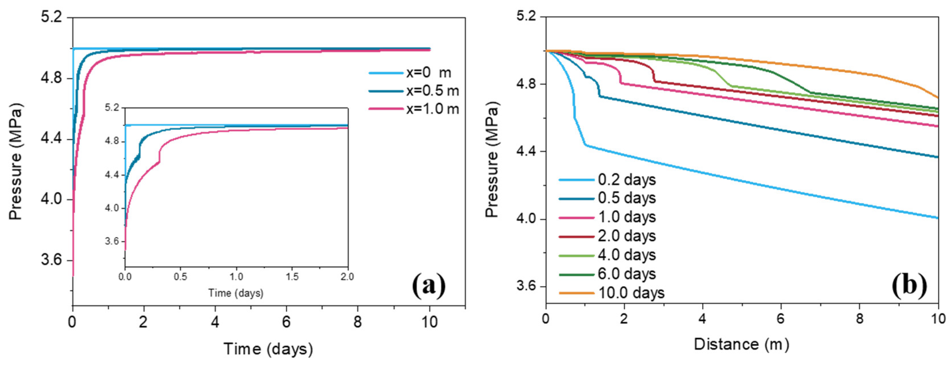
Figure 2 shows the changes of pressure in sediments around the wellbore with time at different locations during N2 injection. As can be seen, since the injection pressure of N2 is 1.5 MPa higher than the original formation pressure, the pore water is displaced after N2 injection and migrates away from the injection point (x = 0 m), so the formation pressure rises. The pressure in the hydrate plugging area rises (0–1 m) to 5 MPa within one day.
Over time, pressure spreads to further distances, and the decomposition of CO2 hydrates leads to an increase in pressure near the injection point (convex curves in Figure 2b). In addition, the rise of pressure may trigger the formation of secondary hydrates in the case of lower temperature and higher CO2 content, which can be demonstrated by changes in temperature, gas saturation composition and hydrate saturation.

3.2. Temperature Change

After N2 injection into the sediments, the variation law of temperature in all locations is the result of the joint action of three aspects: (1) the sensible heat carried by the injected gas increases the formation temperature; (2) the endothermic decomposition of CO2 hydrate decreases the formation temperature; (3) the sediments temperature increases due to the formation of secondary hydrate.
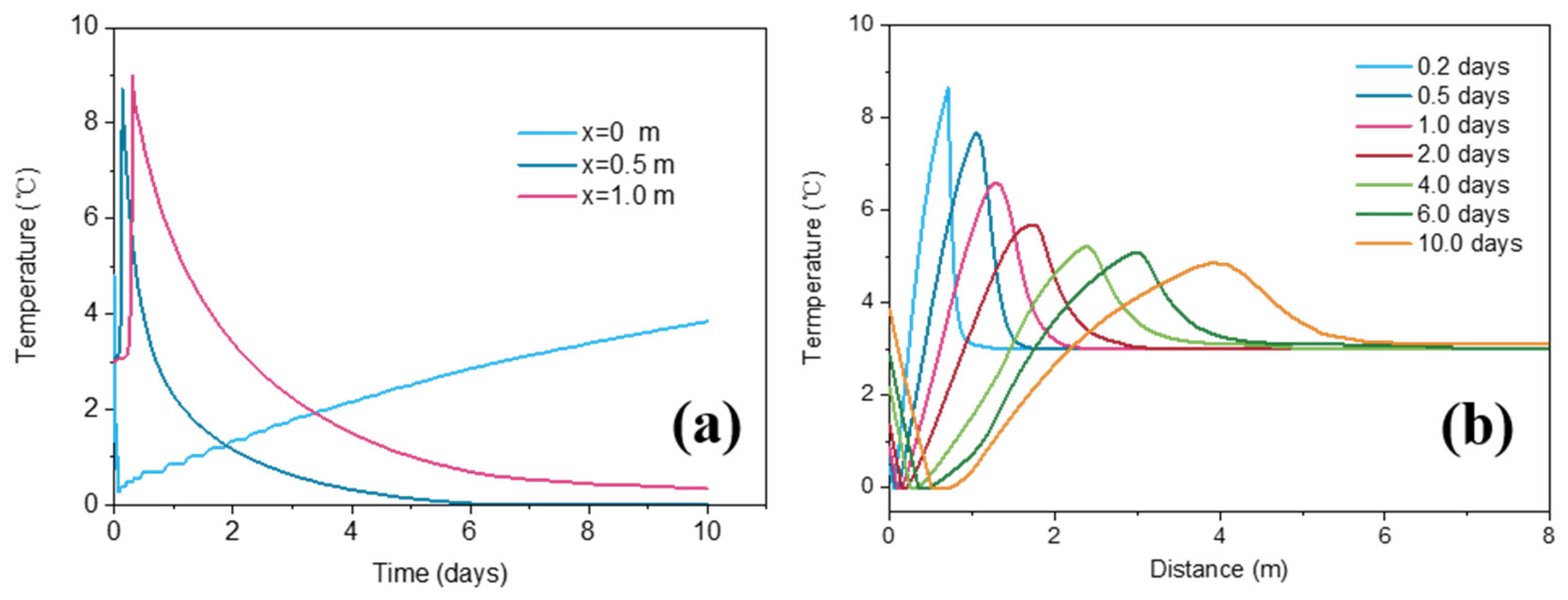
Figure 3a shows the changes in sediment temperature with time at different positions during N2 injection. The initial temperature of the formation and injected gas is 3 °C and 25 °C, respectively. As shown in the figure, after gas injection, the temperature at the injection point (x = 0) drops rapidly and then rises slowly. The temperature at 0.5 m and 1 m away from the injection point showed a rapid rise and then a gradual decline. Figure 3b shows the temperature distribution at different injection times. As can be seen from the figure, as N2 injection begins, the temperature of the CO2 hydrate plugging area (0–1 m) decreases, and the low-temperature area gradually expands and moves away from the injection point with the N2 injection process. In addition, the temperature peak appears on the right side of the low-temperature region and moves away from the injection point with the progress of the gas injection. On the first day of injection, the temperature peak occurred outside the CO2 hydrate plugging zone (x > 1 m).
After N2 injection, the thermodynamic stability of CO2 hydrate is broken, and a large amount of CO2 hydrate at the injection point decomposes and absorbs heat, resulting in lower temperatures at the injection point. With the continuous injection and migration of N2, CO2 hydrate at different points in the sediments continuously decomposes, and the hydrate decomposition area expands, so the temperature of the formation at 0.5 m decreases earlier than that at 1 m. When the hydrate decomposes to a certain extent, a certain amount of sensible heat is brought in with the increase of injected gas, and the formation temperature gradually increases. Thus, the temperature at the injection point and in the hydrate decomposition area first decreases and then gradually increases. It also explains the rightward shift of the low-temperature zone in Figure 3b. When the released CO2 at the injection point reaches x = 0.5 m and x = 1 m, secondary hydrates form under higher pressure (Figure 4a), thus the temperature increases. When the subsequent high concentration of N2 arrives, the hydrate decomposes, resulting in a temperature decrease. The temperature drop at 0.5 m is greater than that at 1 m and is even close to 0 °C on about day 6. This difference may be caused by the difference of CO2 and N2 contents in the gas phase, that is, N2 concentration at 0.5 m is higher than that at 1 m which offers a stronger driving force for CO2 hydrate decomposition.
The appearance of the temperature peak (x < 1 m) in Figure 3b is also the result of secondary hydrate formation at the gas front. Due to the large amount of decomposition of CO2 hydrate at the N2 gas front, the released CO2 may again form hydrates with N2 during migration under a pressure higher than that of the original formation. In the process of migration, CO2 gradually accumulates in the hydrate phase, leading to increases in temperature and N2 content in the gas phase, so the rate and amount of secondary hydrate formation will decrease, and the temperature rise caused by secondary hydrate formation will also be weak. As shown in Figure 4b, the peak temperature outside the hydrate plugging zone gradually decreases with the increase in distance. This can be further demonstrated by the analysis of hydrate saturation evolution.

3.3. Hydrate Saturation Change

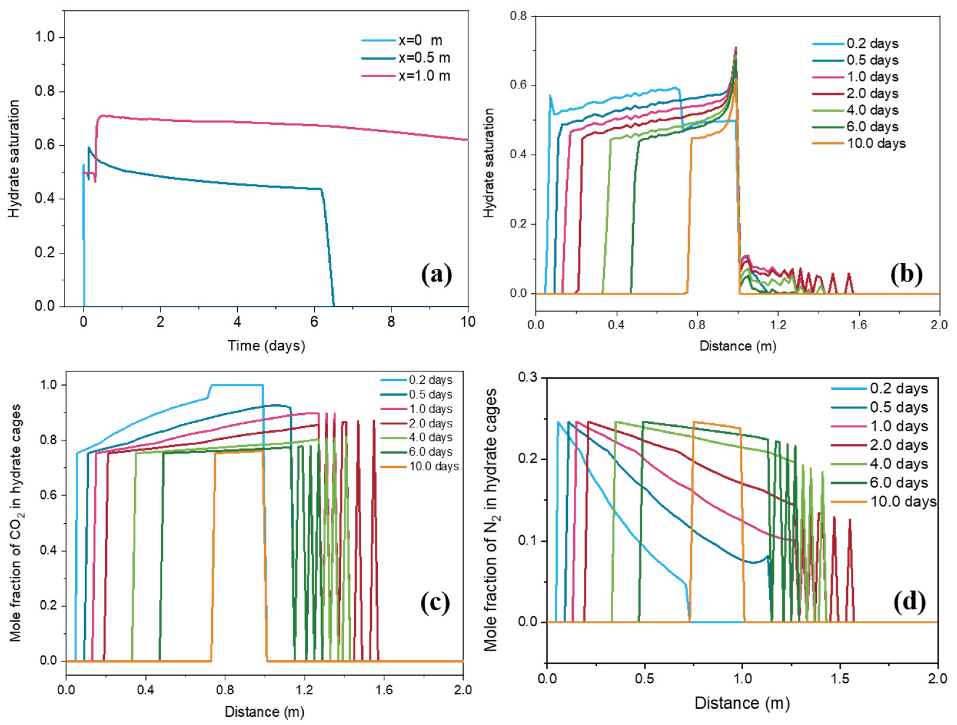
Figure 4 shows the changes in hydrate saturation at different locations with time during N2 injection. As can be seen from Figure 4a, after N2 injection, the hydrate saturation at the injection point quickly reduces to 0 (hydrate completely decomposed), while the locations of 0.5 m and 1 m undergo a process of hydrate saturation decreasing and rising successively. As discussed in Figure 3a, the CO2 hydrate rapidly decomposes after contact with the N2 front, resulting in a decrease in saturation. However, due to the rise of formation pressure and the accumulation of CO2 concentration at the front, secondary hydrates are formed. As can be seen from Figure 4a, the hydrate saturation at 0.5 m increased by about 10% at 0.13 days, and at 0.1 m at 0.4 days increased by about 20%, reaching a maximum of 71%. The formation of secondary hydrates reduces the permeability of the reservoir, slowing down the injection rate of N2 and the migration rate in the reservoir, and leading to a decrease in the removal efficiency of CO2 hydrate in the blocked area.
As can be seen from Figure 4a, after the formation of secondary hydrate, CO2 hydrate at 0.5 m and 1 m begins to decompose under the action of N2, and its hydrate saturation begins to decline, but the rate of hydrate dissociation is different. The hydrate saturation at 0.5 m slowly decreases but drops sharply to 0 around day 6 when the high concentrations of N2 arrive, while the hydrate saturation at 1 m is always at a high level during this period (Figure 4b). As mentioned above, this difference is due to lower formation temperatures and higher CO2 concentration in the gas phase at x = 1 m (Figure 3). It is worth noting that hydrates with low saturation also appears outside the hydrate blockage zone, and the farther away from the blockage zone, the lower the hydrate saturation. This indicates that the gas composition of the gas coming from x = 1 m can still form hydrates under the temperature and pressure conditions in this region. The hydrate-free region (x > 1.6 m) can be explained by the following two points: (1) During the formation of secondary hydrates (0–1 m, especially at x = 1 m), a large amount of CO2 was captured and fixed in hydrate cages, leading to higher N2 content in the gas phase (2) The exothermic effect accompanying the formation of hydrates causes an increase in temperature. Therefore, gas in this region with high N2 content and temperature can no longer form hydrates.
Figure 4c,d shows the changes in CO2 and N2 content in the hydrate phase during N2 injection. As can be seen from the figure, with the presence of N2, the content of CO2 in the hydrate phase decreases, while the content of N2 increases to a maximum value of 25% (The maximum N2 molar fraction when hydrate can exist stably under formation temperature and pressure conditions). This also shows that the secondary hydrate forms a mixed hydrate of CO2 and N2.

3.4. Gas Saturation Change

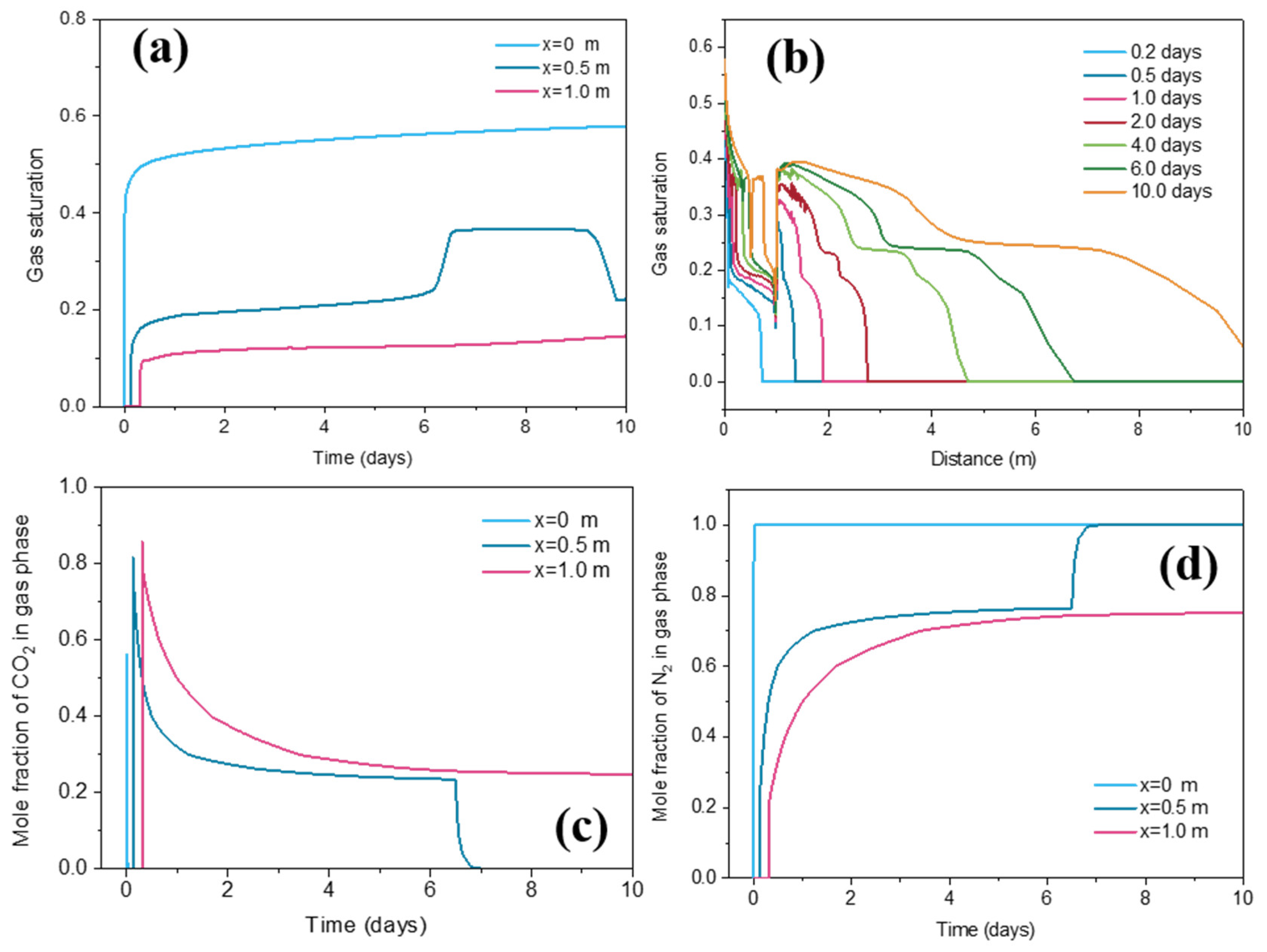
Figure 5 shows the evolutions of gas saturation and gas composition at different positions with time during N2 injection. As can be seen from the figure, as N2 is injected, the gas saturation at different locations shows a sudden increase trend and then slows down, and the gas saturation at the locations of 0.5 m and 1 m is significantly lower than the injection point. This is because the injected gas continuously displaces the pore water away from the injection point. Within the first 6 days, the mole fraction of N2 in the gas phase at 0.5 m and 1 m increases rapidly, but the molar fraction of CO2 at 1 m is higher than the value at 0.5 m. This is because the released CO2 from the CO2 hydrate migrates away from the injection point under the driving force of gas injection.
Moreover, due to the pressure gradient decreases (caused by hydrate dissociation near the injection point, as can be seen in Figure 2b) and the decreased permeability of the reservoir (caused by secondary hydrate formation), the gas migration in the reservoir slows down, which easily leads to the accumulation of CO2 generated by decomposition at the front. Therefore, in the process of N2 injection, the CO2 content in the front is high, and the N2 content in the region after N2 displacement is high. As discussed above (Figure 4a), due to the difference in gas composition, the hydrate behaviour at different points is different. The gas saturation at 0.5 m suddenly increases on about day 6, then continues to stabilize for 3 days, and begins to decline around day 9. This sudden increase in gas composition is caused by the arrival of the gas with high N2. It can be seen from Figure 5c,d that the concentration of N2 in the gas phase at 0.5 m on day 6 is close to 100%, while the concentration of CO2 decreases sharply. Accordingly, as shown in Figure 4a, CO2 hydrate decomposes rapidly on the sixth day, and the saturation drops to 0 very quickly. These also confirm the analysis above in Figure 3 and Figure 4.

3.5. Comparison of N2 Injection and Depressurization

Figure 6 shows the influence of injection pressure and temperature on the changes in residual saturation of CO2 hydrate under different conditions of depressurization and N2 injection. It can be seen from the figure that with the increase of N2 injection pressure, the dissociation rate of CO2 hydrate significantly accelerates. Under the same temperature (25 °C) and N2 injection pressure of 4.5 MPa and 5 MPa, the residual saturation of hydrate after 10 days is 52% and 23%, respectively. When the injection pressure is increased to 5.5 MPa and 6.5 MPa, the residual hydrate saturation drops to 0 at 9.6 and 5.8 days, respectively. Thus, the higher the N2 injection pressure, the more beneficial it is to eliminate the hydrate blockage. It can also be seen that under the same injection pressure, the rate of hydrate dissociation is not improved significantly when the injection temperature increases, especially when the injection pressure is at 5 MPa (compared to 4.5 MPa). On the one hand, because the heat-carrying capacity of the gas is poor, the heat loss is fast after injection into the sediments. On the other hand, when the injection pressure is higher (5 MPa), the gas flow rate is faster, and reducing the methane partial pressure is the main factor for hydrate decomposition. When the gas injection pressure is relatively low (4.5 MPa), the heat transfer through conduction plays a certain role in the decomposition of CO2 hydrates. Overall, reducing methane partial pressure is the controlling factor for hydrate decomposition when using N2 injection to remove hydrate blockages, rather than an increase in reservoir temperature caused by the sensible heat carried by the injected gas.
Figure 6 also compares the effects of N2 injection and depressurization on the residual saturation of hydrate. As can be seen from the figure, when the local formation is depressurized to 2.5 MPa, the hydrate saturation in the sediments remains at 70% for 10 days. Even if the pressure drops to 1.5 MPa, the remaining hydrate saturation reaches 30% after 10 days. This shows that compared with the N2 injection method, the direct depressurization method makes it difficult to quickly remove the blocked CO2 hydrate. Because the temperature and pressure conditions of CO2 formation are relatively mild, the reservoir pressure needs to be greatly reduced to stimulate its decomposition. The decrease of reservoir temperature in the process of decomposition will reduce the driving force of hydrate decomposition and slow down the hydrate decomposition. Unlike pressure reduction, continuous nitrogen injection can displace CO2 released from CO2 hydrate decomposition and always maintain a high N2 concentration in the CO2 hydrate decomposition area, so CO2 hydrate decomposition can always maintain a high driving force, which is also the main advantage of nitrogen injection plugging removal method.

4. Conclusions

CO2 sequestration as solid hydrate is a potential way to capture and store the anthropogenic CO2. The removal of CO2 hydrate blockage may be a challenge involved in hydrate-based CO2 sequestration. In this work, an N2 injection method was proposed to remove hydrate blockage. A numerical study on the effectiveness of N2 injection on the removal of CO2 hydrate blockage was conducted using TOUGH+MIXHYD. Several major conclusions can be drawn:
(1)
Compared with the direct depressurization method, N2 injection can quickly remove the blocked CO2 hydrate. The CO2 hydrate dissociation rate can be improved by increasing the N2 injection pressure. N2 injection temperature has a relatively weak effect on the removal of CO2 hydrate blockage;
(2)
The injection of N2 can lead to the rise of sediment pressure. With the influence of injected N2, rapid CO2 hydrate dissociation can decrease the temperature of sediments. However, with the combined effect of temperature, pressure, and gas composition, secondary CO2-N2 hydrate can be formed far away from the injection point and lead to the rise of local temperature and hydrate saturation. The continuous injection of N2 can eliminate the secondary hydrate formation;
(3)
Our work provides a new method for eliminating the problem of hydrate blockage, which has prominent significance for the development of hydrate-based CO2 geological storage technology.

Author Contributions

Conceptualization, N.L. and J.K.; methodology, T.L., L.Y. and W.L. (Wei Li); validation, L.Y., W.L. (Wei Li) and W.L. (Wei Luo); formal analysis, J.K. and X.X.; investigation, T.L.; resources, T.L. and L.Y.; data curation, N.L.; writing—original draft preparation, N.L. and J.K.; writing—review and editing, J.K.; visualization, X.X.; supervision, N.L.; project administration, N.L. and J.K. All authors have read and agreed to the published version of the manuscript.

Funding

This work was financially supported by the Research Foundation of China University of Petroleum-Beijing at Karamay (XQZX20230019), National Natural Science Foundation of China (Nos. 22008258, 52204061), Natural Science Foundation of Xinjiang Uygur Autonomous Region (2022D01B143) and “Tianchi Talent” Recruitment Program.

Data Availability Statement

The data that support the findings of this paper are available upon request.

Conflicts of Interest

Authors Tao Liao, Liang Yuan, Wei Li and Wei Luo were employed by the company PetroChina Xinjiang Oilfield Company. The remaining authors declare that the research was conducted in the absence of any commercial or financial relationships that could be construed as a potential conflict of interest.

Nomenclature

CRheat capacity of the dry rock (J/kg/K)
ggravitational acceleration (m/s2)
henthalpy of phase β or component κ in phase β (J/kg)
kintrinsic permeability (m2)
krrelative permeability of phase β
madvective mass flux vector of phase β (kg/m2/s)
nthe inward unit normal vector
Ppressure (Pa)
P1entry capillary pressure (Pa)
qsource/sink term of mass component κ (kg/m3/s)
Qdisshydrate dissociation heat (J/m3)
ssource/sink term of heat (J/m3/s)
Sphase saturation
Ttemperature (°C)
Uthe internal energy of phase β (J/kg)
Vvolume (m3)
ϕporosity
λRcomposite thermal conductivity (W/m/K)
λRDdry thermal conductivity (W/m/K)
λRWwet thermal conductivity (W/m/K)
λIthermal conductivity of ice (W/m/K)
μviscosity of phase β (Pa s)
ρdensity of phase β (kg/m3)
ρRrock density (kg/m3)
Subscripts and superscripts
bvan Genuchten exponent
capcapillary
irAirreducible aqueous phase
irGirreducible gas phase
nApermeability reduction exponent for the aqueous phase
nGpermeability reduction exponent for gas phase
βphase (G = gas, A = aqueous, H = hydrate, I = ice)
κmass component (n = nitrogen, c = carbon dioxide, w = water)

References

  1. Sloan, E.D.; Koh, C.A. Clathrate Hydrate of Natural Gases, 3rd ed.; CRC Press: Boca Raton, FL, USA, 2008. [Google Scholar]
  2. Boswell, R.; Collett, T.S. Current perspectives on gas hydrate resources. Energy Environ. Sci. 2011, 4, 1206–1215. [Google Scholar] [CrossRef]
  3. Zhao, J.; Zhu, Z.; Song, Y.; Liu, W.; Zhang, Y.; Wang, D. Analyzing the process of gas production for natural gas hydrate using depressurization. Appl. Energy 2015, 142, 125–134. [Google Scholar] [CrossRef]
  4. Wang, Y.; Li, X.S.; Li, G.; Zhang, Y.; Li, B.; Feng, J. A three-dimensional study on methane hydrate decomposition with different methods using five-spot well. Appl. Energy 2013, 112, 83–92. [Google Scholar] [CrossRef]
  5. Zhao, J.; Zheng, J.; Li, F.; Yang, M. Gas permeability characteristics of marine sediments with and without methane hydrates in a core holder. J. Nat. Gas. Sci. Eng. 2020, 76, 103215. [Google Scholar] [CrossRef]
  6. Okwananke, A.; Hassanpouryouzband, A.; Farahani, M.V.; Yang, J.; Tohidi, B.; Chuvilin, E.; Istomin, V.; Bukhanov, B. Methane recovery from gas hydrate-bearing sediments: An experimental study on the gas permeation characteristics under varying pressure. J. Petrol. Sci. Eng. 2019, 180, 435–444. [Google Scholar] [CrossRef]
  7. Le, Q.D.; Rodriguez, C.T.; Legoix, L.N.; Pirim, C.; Chazallon, B. Influence of the initial CH4-hydrate system properties on CO2 capture kinetics. Appl. Energy 2020, 280, 115843. [Google Scholar] [CrossRef]
  8. Ohgaki, K.; Takano, K.; Sangawa, H.; Matsubara, T.; Nakano, S. Methane exploitation by CO2 from gas hydrates—Phase equilibria for CO2-CH4 mixed hydrate system. J. Chem. Eng. JPN 1996, 29, 478–483. [Google Scholar] [CrossRef]
  9. Yuan, Q.; Sun, C.Y.; Liu, B.; Yang, X.; Ma, P.C.; Ma, Z.W.; Ma, Q.L.; Yang, L.Y.; Chen, G.J. Recovery of methane from hydrate reservoir with gaseous CO2 using a three-dimensional middle-size reactor. Energy 2012, 40, 47–58. [Google Scholar] [CrossRef]
  10. Yuan, Q.; Sun, C.Y.; Yang, X.; Wang, X.H.; Ma, Z.W.; Ma, Q.L.; Yang, L.Y.; Chen, G.J.; Li, Q.P.; Li, S. Methane recovery from natural gas hydrate in porous sediment using pressurized liquid CO2. Energ. Convers. Manag. 2013, 67, 257–264. [Google Scholar] [CrossRef]
  11. Yuan, Q.; Wang, X.H.; Dandekar, A.; Sun, C.Y.; Li, Q.P.; Ma, Z.W.; Liu, B.; Chen, G.J. Replacement of methane from hydrates in porous sediments with CO2-in-water emulsions. Ind. Eng. Chem. Res. 2014, 53, 12476–12484. [Google Scholar] [CrossRef]
  12. Park, Y.; Kim, D.Y.; Lee, J.W.; Huh, D.G.; Park, K.P.; Lee, J.; Lee, H. Sequestering CO2 into complex structures of naturally occurring gas hydrates. Proc. Natl. Acad. Sci. USA 2006, 103, 12690–12694. [Google Scholar] [CrossRef]
  13. Kang, H.; Koh, D.Y.; Lee, H. Nondestructive natural gas hydrate recovery driven by air and CO2. Sci. Rep. 2014, 4, 6616. [Google Scholar] [CrossRef]
  14. Li, B.; Xu, T.; Zhang, G.; Guo, W.; Liu, H.; Wang, Q.; Qu, L.; Sun, Y. An experimental study on gas production from fracture-filled hydrate by CO2 and CO2/N2 replacement. Energ. Convers. Manag. 2018, 165, 738–747. [Google Scholar] [CrossRef]
  15. Yang, J.; Okwananke, A.; Tohidi, B.; Chuvilin, E.; Maerle, K.; Istomin, V.; Bukhanov, B.; Cheremisin, A. Flue gas injection into gas hydrate reservoirs for methane recovery and CO2 sequestration. Energ. Convers. Manag. 2017, 136, 431–438. [Google Scholar] [CrossRef]
  16. Hassanpouryouzband, A.; Yang, J.; Okwananke, A.; Burgass, R.; Thohidi, B.; Chuvilin, E.; Istomin, V.; Bukhanov, B. An experimental investigation on the kinetics of integrated methane recovery and CO2 sequestration by injection of flue gas into permafrost methane hydrate reservoirs. Sci. Rep. 2019, 9, 16206. [Google Scholar] [CrossRef] [PubMed]
  17. Schoderbek, D.; Martin, K.L.; Howard, J.; Silpngarmlert, S.; Hester, K. North slope hydrate fieldtrial: CO2/CH4 exchange. In Proceedings of the Arctic Technology Conference, Houston, TX, USA, 3–5 December 2012. [Google Scholar]
  18. Wang, X.H.; Sun, Y.F.; Wang, Y.F.; Li, N.; Sun, C.Y. Gas production from hydrates by CH4-CO2/H2 replacement. Appl. Energy 2017, 188, 305–314. [Google Scholar] [CrossRef]
  19. Cao, L.Y.; Qian, W.M.; Gong, P.; Guan, S.; Duan, Y.; He, Y. Application Practices and Evaluation of Gas Injection Technology for CO2 Flooding in Subei Oilfield. Xinjiang Oil Gas 2022, 18, 46–50. [Google Scholar]
  20. Xiong, X.Q.; Liao, T.; Xing, X.K.; Zhang, Z.; Dong, Z.; Bi, Y. Study Progress on Characteristics and Separation of Produced Fluid of CO2 Flooding. Xinjiang Oil Gas 2022, 18, 33–39. [Google Scholar]
  21. Zhao, Z.G.; Zhao, B.; Yang, H.J.; He, C.Z. Methods to prevent blockage of natural gas hydrates. Xinjiang Oil Gas 2009, 5, 81–83. [Google Scholar]
  22. Liang, S.; Gao, F.X.; Yue, G.; Liu, Z.Q.; Sun, Q.; Wang, Y.W.; Liu, A.X.; Guo, X.Q. Research on the Preparation of Civil Natural Gas from Oil Shale Retorting Gas by the Hydration Process. Xinjiang Oil Gas 2021, 17, 56–61. [Google Scholar]
  23. Wang, X.H.; Sun, C.Y.; Chen, G.J.; He, Y.N.; Sun, Y.F.; Wang, Y.F.; Li, N.; Zhang, X.X.; Liu, B.; Yang, L.Y. Influence of gas sweep on methane recovery from hydrate-bearing sediments. Chem. Eng. Sci. 2015, 134, 727–736. [Google Scholar] [CrossRef]
  24. Hassanpouryouzband, A.; Joonaki, E.; Vasheghani Farahani, M.; Takeya, S.; Ruppel, C.; Yang, J.; English, N.J.; Schicks, J.M.; Edlmann, K.; Mehrabian, H.; et al. Gas hydrates in sustainable chemistry. Chem. Soc. Rev. 2020, 49, 5225–5309. [Google Scholar] [CrossRef] [PubMed]
  25. Moridis, G.; Kowalsky, M.; Pruess, K. TOUGH+ HYDRATE v1. 0 User’s Manual: A Code for the Simulation of System Behaviour in Hydrate-Bearing Porous Media; Lawrence Berkeley National Laboratory Report LBNL-149E; Lawrence Berkeley National Laboratory: Berkeley, CA, USA, 2008. [Google Scholar]
  26. Konno, Y.; Masuda, Y.; Hariguchi, Y.; Masuda, Y.; Hariguch, Y.; Kurihara, M.; Ouchi, H. Key factors for depressurization-induced gas production from oceanic methane hydrates. Energy Fuels 2010, 24, 1736–1744. [Google Scholar] [CrossRef]
  27. Anderson, B.J.; Kurihara, M.; White, M.D.; Moridis, G.J.; Wilson, S.J.; Darvish, M.P.; Gaddipati, M.; Masuda, Y.; Collett, T.; Hunter, R.B.; et al. Regional long-term production modeling from a single well test, Mount Elbert Gas Hydrate Stratigraphic Test Well, Alaska North Slope. Mar. Petrol. Geol. 2011, 28, 493–501. [Google Scholar] [CrossRef]
  28. Yonkofski, C.M.; Horner, J.A.; White, M.D. Experimental and numerical investigation of hydrate-guest molecule exchange kinetics. J. Nat. Gas. Sci. Eng. 2016, 35, 1480–1489. [Google Scholar] [CrossRef]
  29. Kan, J.Y.; Sun, Y.; Dong, B.C.; Yuan, Q.; Liu, B.; Sun, C.Y.; Chen, G.J. Numerical simulation of gas production from permafrost hydrate deposits enhanced with CO2/N2 injection. Energy 2021, 221, 119919. [Google Scholar] [CrossRef]
  30. Chen, G.J.; Guo, T.M. A new approach to gas hydrate modelling. Chem. Eng. J. 1998, 71, 145–151. [Google Scholar] [CrossRef]
  31. van Genuchten, M.T. A closed-form equation for predicting the hydraulic conductivity of unsaturated soils. Soil. Sci. Soc. Am. J. 1980, 44, 892–898. [Google Scholar] [CrossRef]
Figure 1. The schematic depiction of the geological setting.
Processes 12 00204 g001
Figure 2. Pressure evolution in sediment during N2 injection: (a) Pressure variation with time, (b) Spatial distribution of pressure.
Processes 12 00204 g002
Figure 3. Temperature evolution in sediment during N2 injection: (a) Temperature variation with time, (b) Spatial distribution of temperature.
Processes 12 00204 g003
Figure 4. Hydrate saturation evolution in sediment during N2 injection: (a) Hydrate saturation variation with time, (b) spatial distribution of hydrate saturation, (c) mole fraction of CO2 in hydrate phase, (d) mole fraction of N2 in hydrate phase.
Processes 12 00204 g004
Figure 5. Gas saturation evolution in sediment during N2 injection: (a) Gas saturation variation with time, (b) spatial distribution of gas saturation, (c) mole fraction of CO2 in the gas phase, (d) mole fraction of N2 in the gas phase.
Processes 12 00204 g005
Figure 6. Temporal variation of residual saturation of hydrate under different conditions of depressurization and N2 injection.
Processes 12 00204 g006
Table 1. Model parameters and geological properties.
ParameterValue & Unit
Temperature3 °C
Pressure3.5 MPa
Hydrate saturation0.50
Intrinsic permeability5.0 × 10−14 m2
Porosity0.30
Composite thermal conductivity model [25] λ R = λ RD + ( S A 1 / 2 + S H 1 / 2 ) ( λ RW λ RD ) + ϕ S I λ I
λRD = 1.0 W/m/K
λRW = 3.1 W/m/K
Relative permeability model [31] S A * = S A S irA / 1 S irA
S G * = S G S irG / 1 S irG
k rA = S A * n A ; k rG = S G * n G
nA = 3.5, nG = 3.5, SirA = 0.3, SirG = 0.05
Capillary pressure model [25] P cap = P 1 [ S A * ] 1 / b 1 1 b
S A * = S A S irA / 1 S irA
b = 0.45, P1 = 105 Pa
Table 2. Simulation scenarios *.
Simulation IDPinj (MPa)Tinj (°C)
A14.525
A24.550
A3510
A4525
A5550
A65.525
A75.550
B11.5(Pdep)
B22.5(Pdep)
* Pinj: pressure of N2 injection; Tinj: temperature of N2 injection; Pdep: pressure of well bore during depressurization.
Disclaimer/Publisher’s Note: The statements, opinions and data contained in all publications are solely those of the individual author(s) and contributor(s) and not of MDPI and/or the editor(s). MDPI and/or the editor(s) disclaim responsibility for any injury to people or property resulting from any ideas, methods, instructions or products referred to in the content.