
Research Status and Development Trend of Cylindrical Gas Film Seals for Aeroengines

Abstract
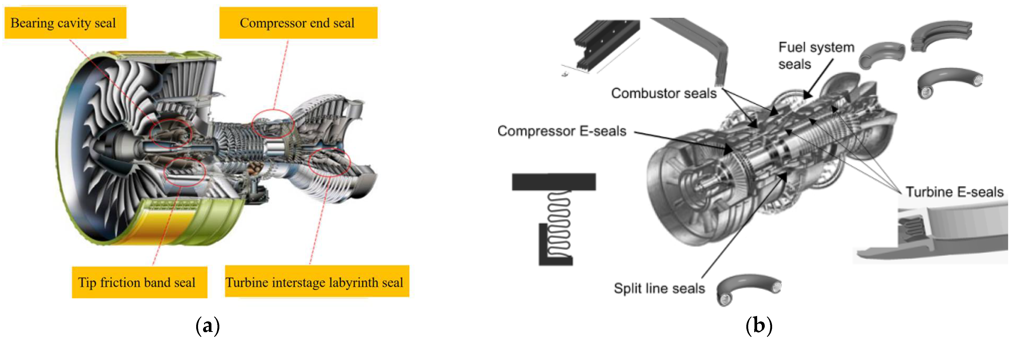
:1. Introduction
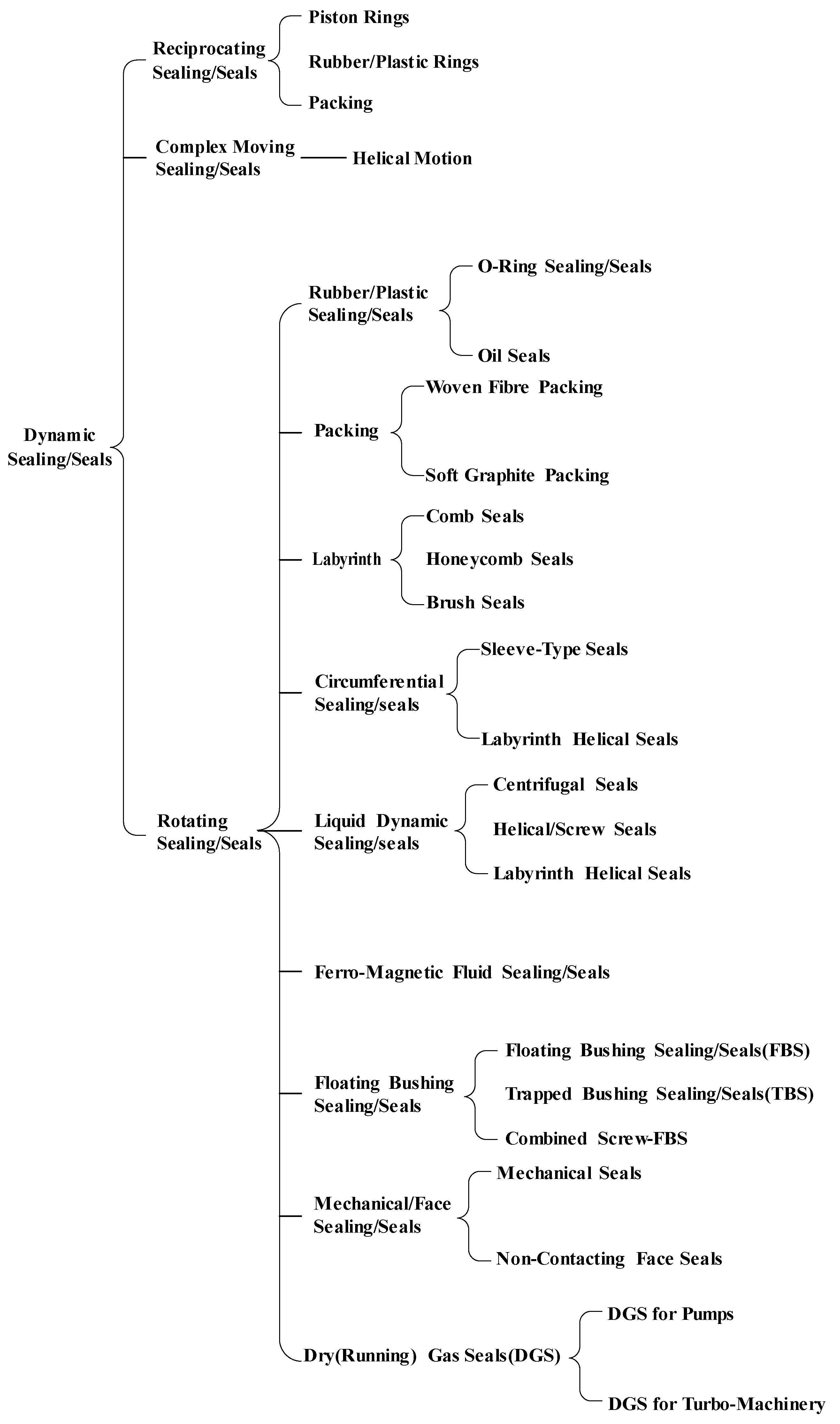
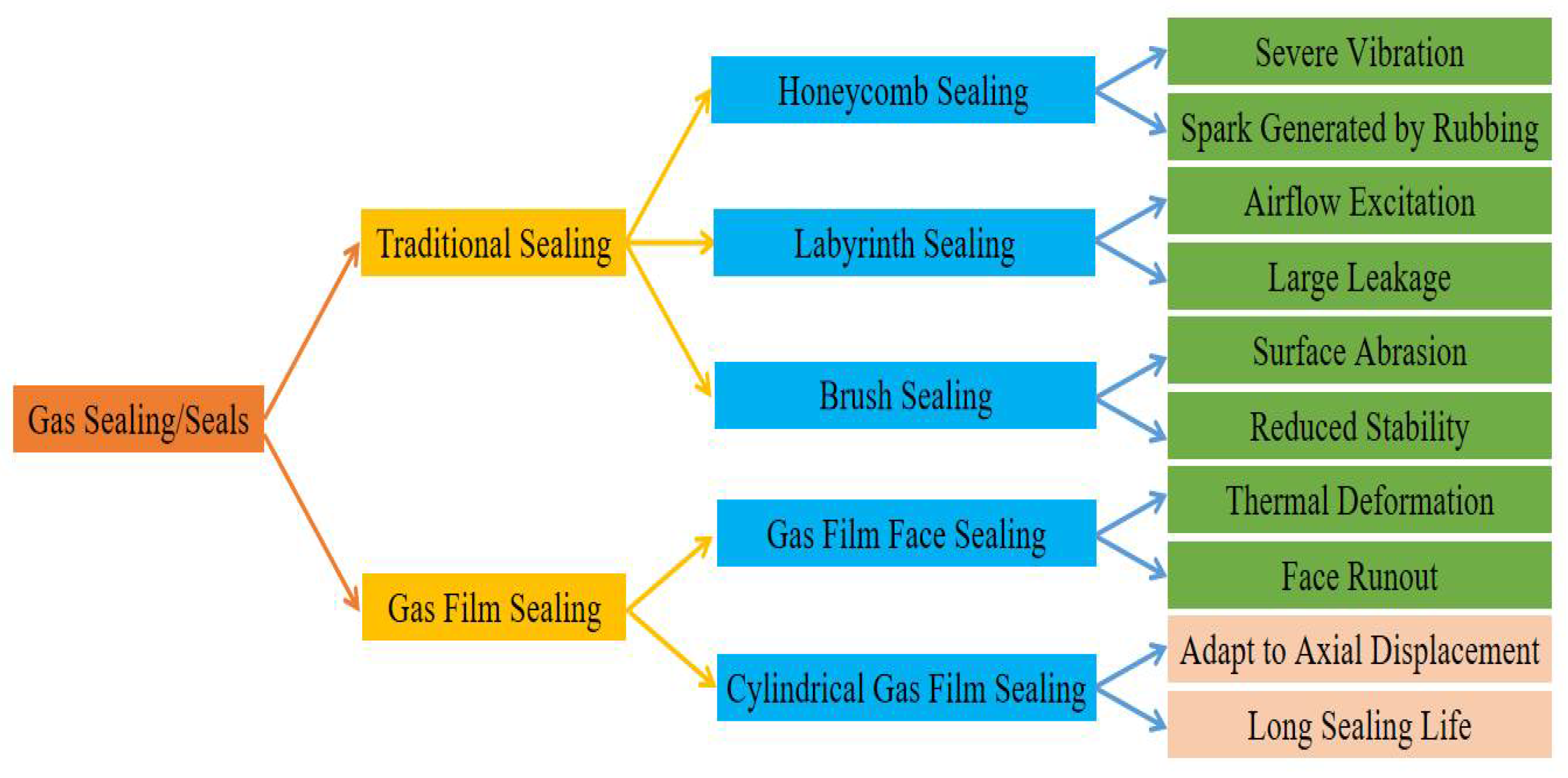
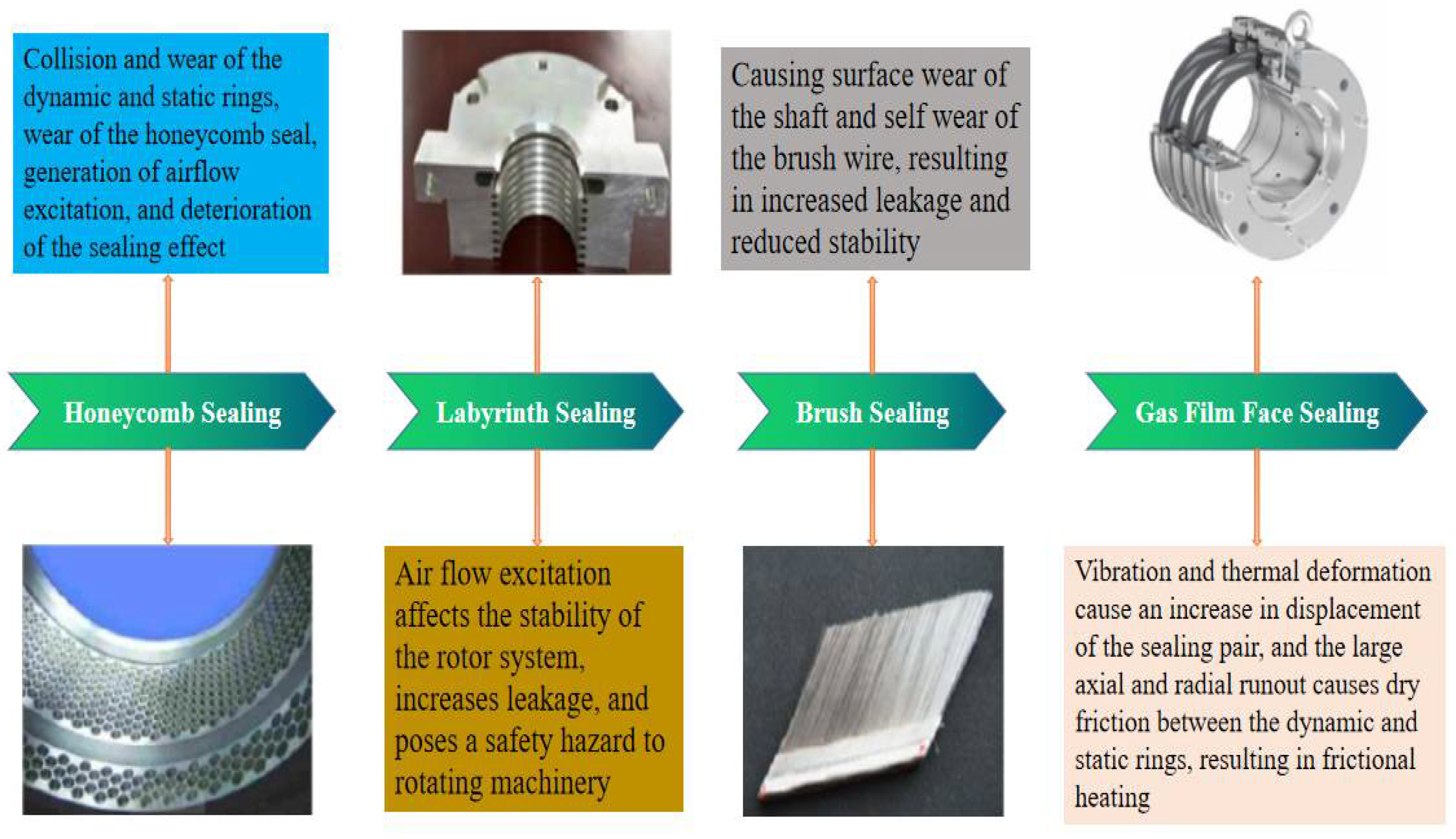
2. Comparison of the Characteristics of Different Gas Sealing Forms
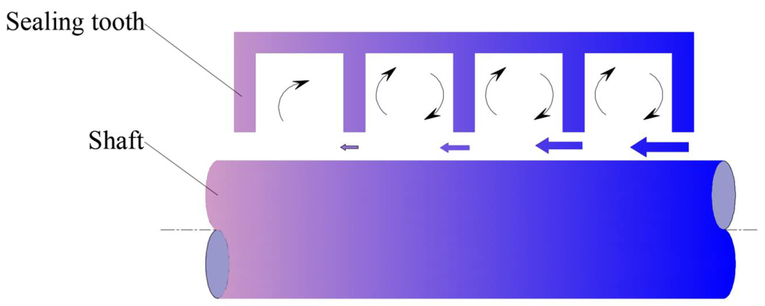
2.1. Labyrinth Seal
2.2. Brush Seal
- (1)
- In the flow, friction, deformation of the brush seal, in addition to the study of the leakage flow characteristics and mechanical properties of the brush seal, should also be considered in a comprehensive manner, such as the deformation of the brush filament and other fluid–solid coupling effects.
- (2)
- In terms of the friction heat effect and heat transfer characteristics of the brush seal, it is necessary to study the brush seal in depth using experimental measurements and numerical simulations, to find out the influence laws of the geometrical structural parameters and effect of the operating conditions on the friction heat effect and heat transfer characteristics, and to improve the structure of the brush seal to avoid, as far as possible, the high temperature of the brush wire of the brush seal when it is in operation.
- (3)
- In the study of dynamic characteristics of the brush seal rotor, based on the experimental study of the dynamic characteristics of the brush seal rotor, develop a fast and accurate numerical prediction method for evaluating the dynamic characteristics of the brush seal rotor.
- (4)
- In the structural design of the brush seal, based on the leakage control mechanism of the brush seal, the friction and heat transfer mechanism, and the contact force and the deformation mechanism of the brush filaments, reduce the unfavorable effects of the brush filament abrasion, friction, and heat effects between the brush filaments and the rotor and the hysteresis effects on the sealing performance through the improvement of the structure and form of the brush seal.
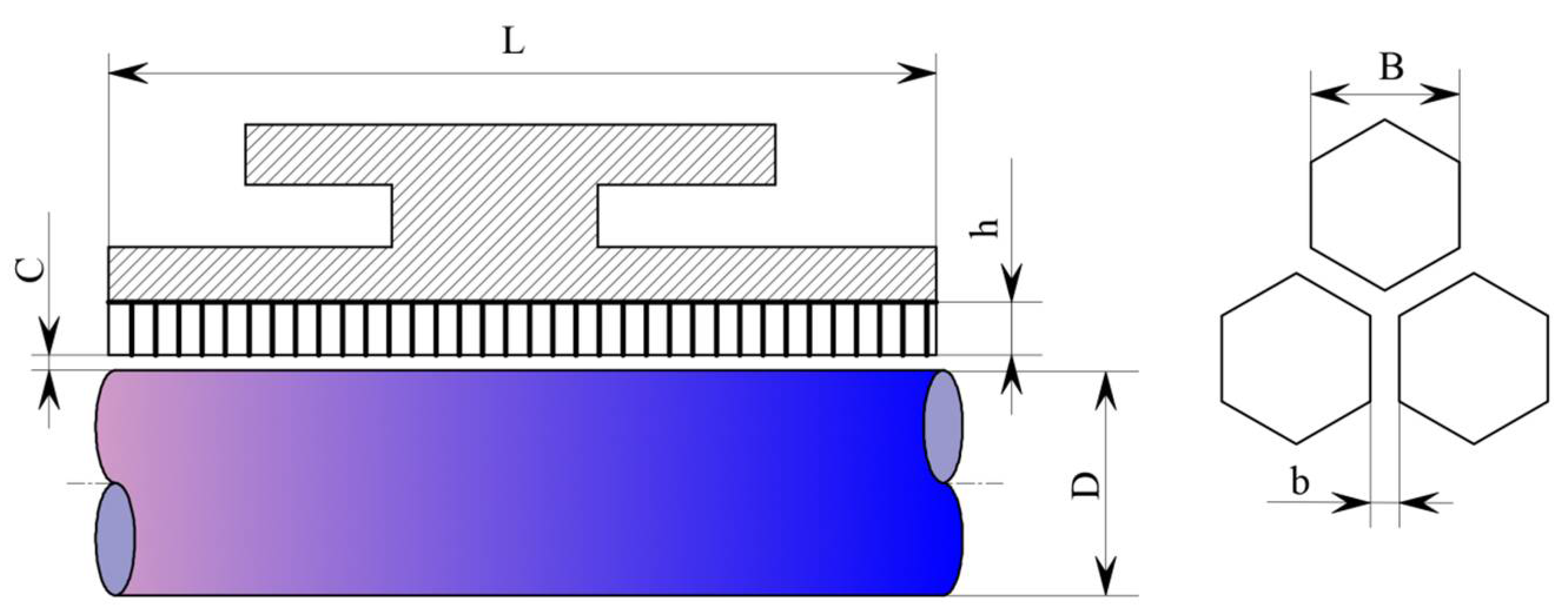
2.3. Honeycomb Seal
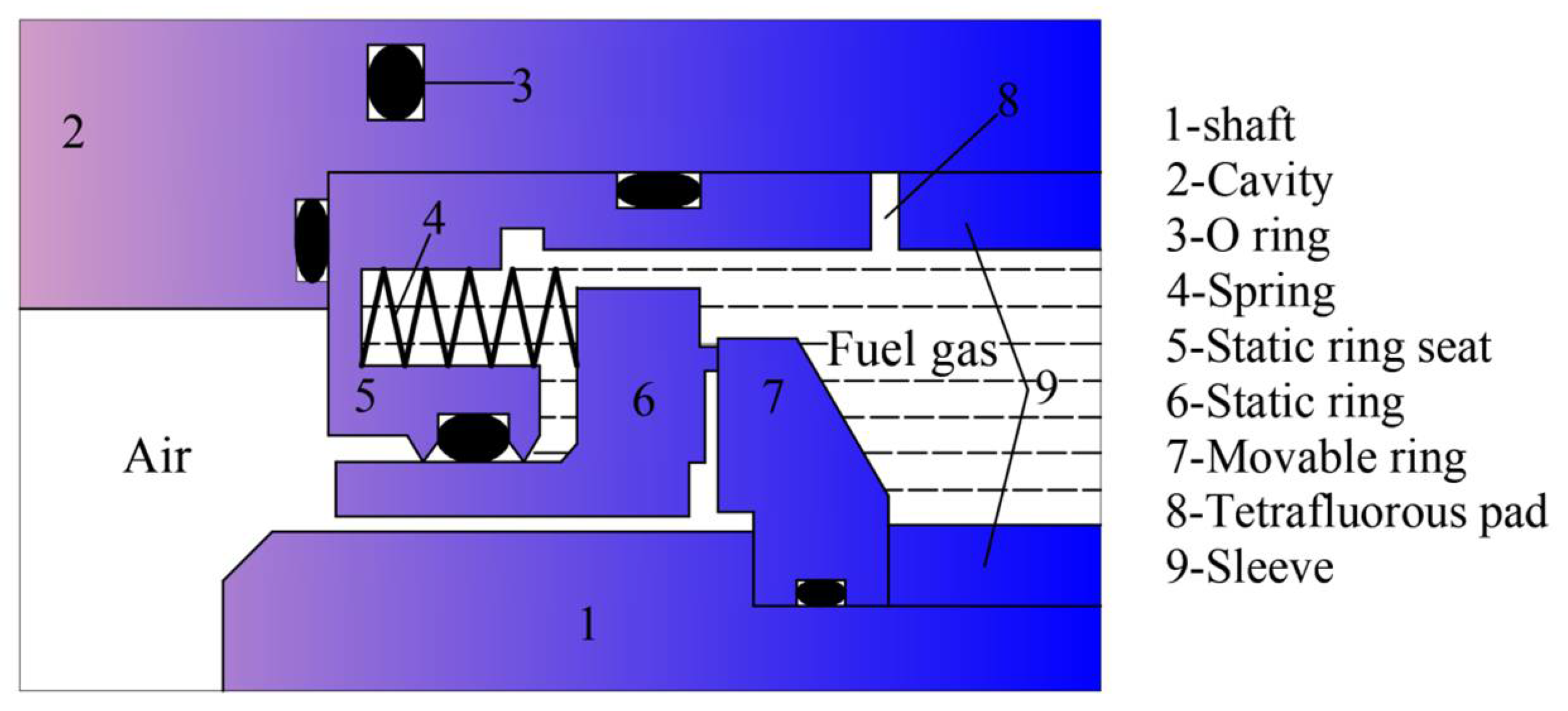
2.4. Gas Film Face Seal
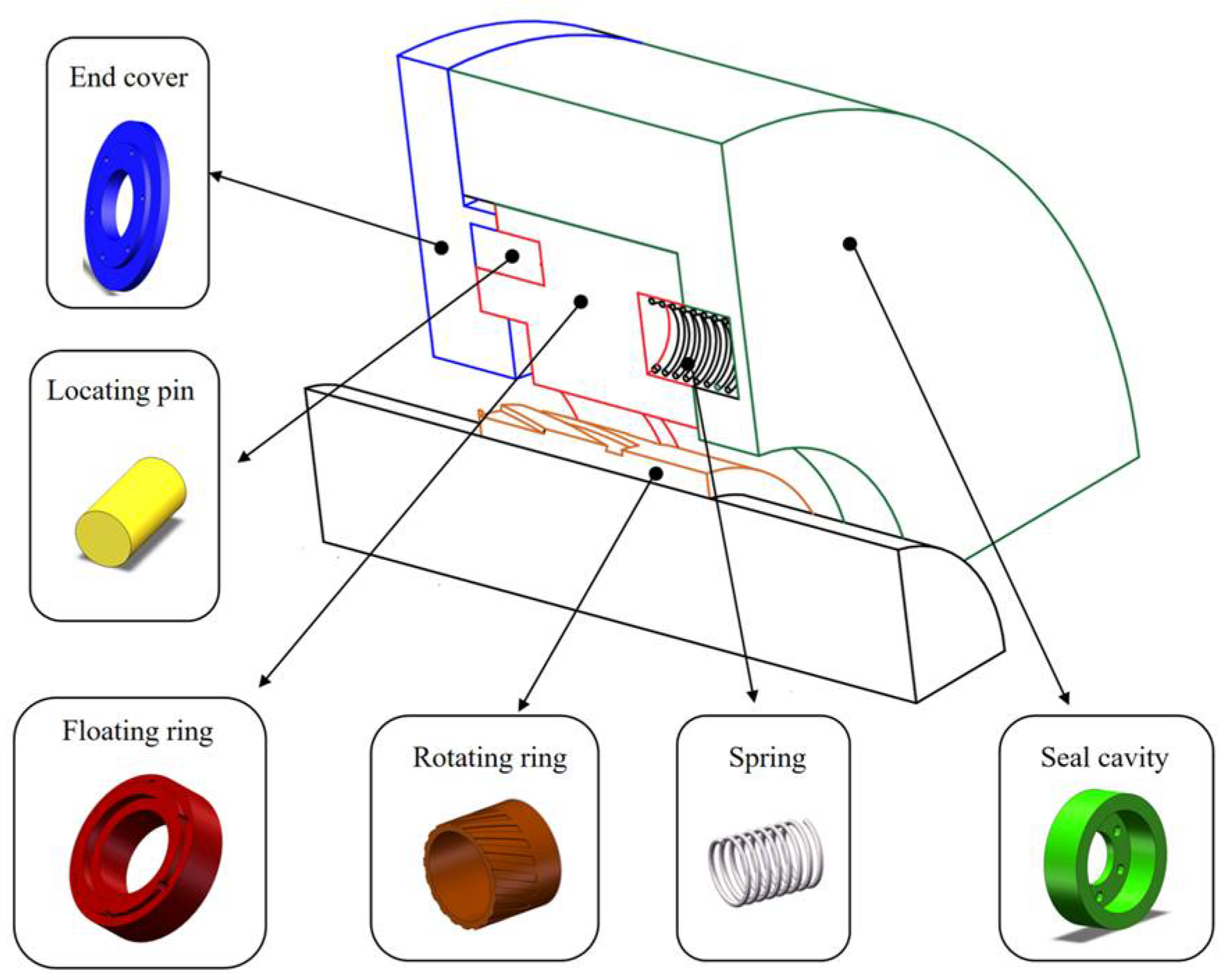
3. Cylindrical Gas Film Seal Structure Type and Working Principle
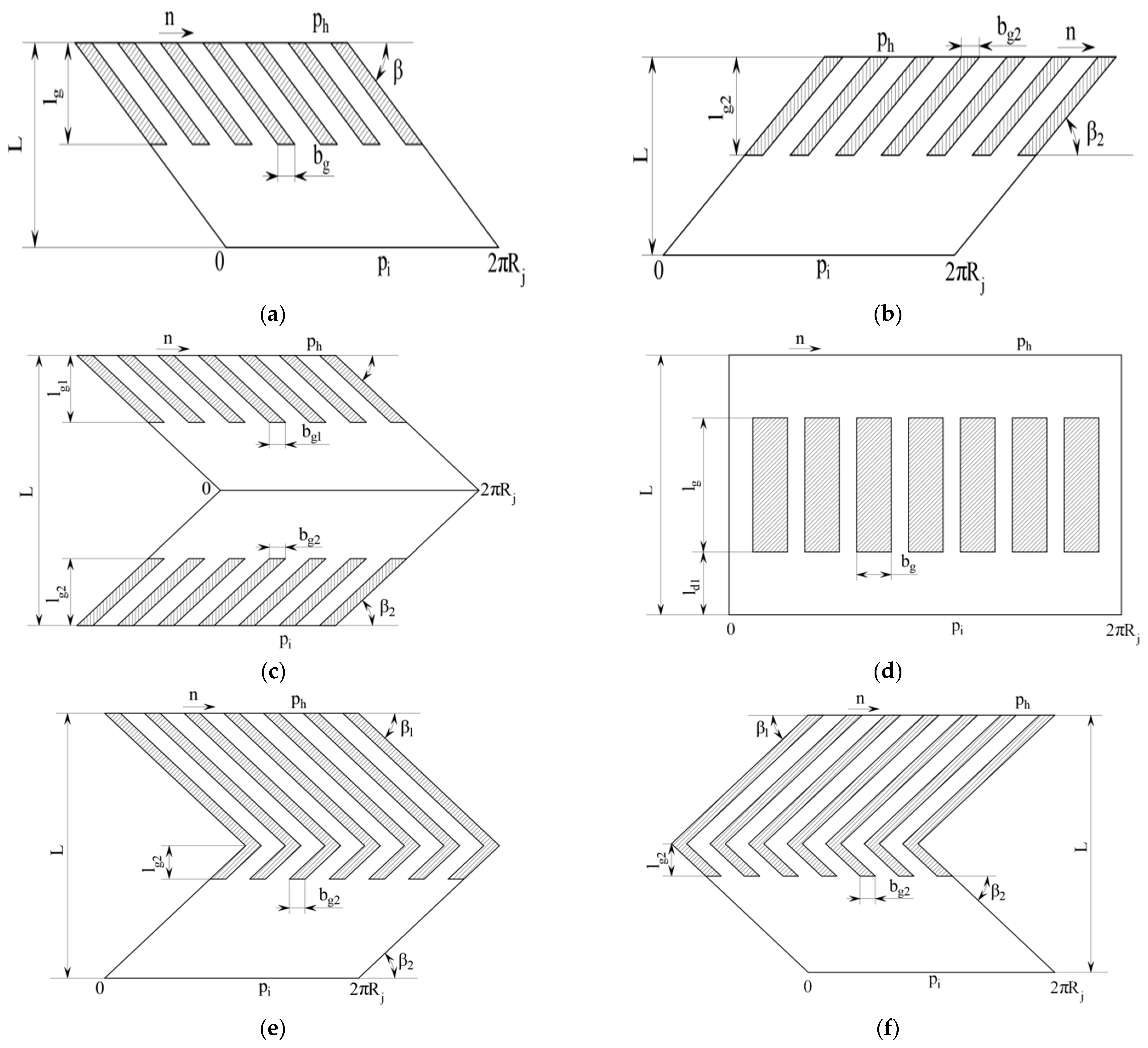
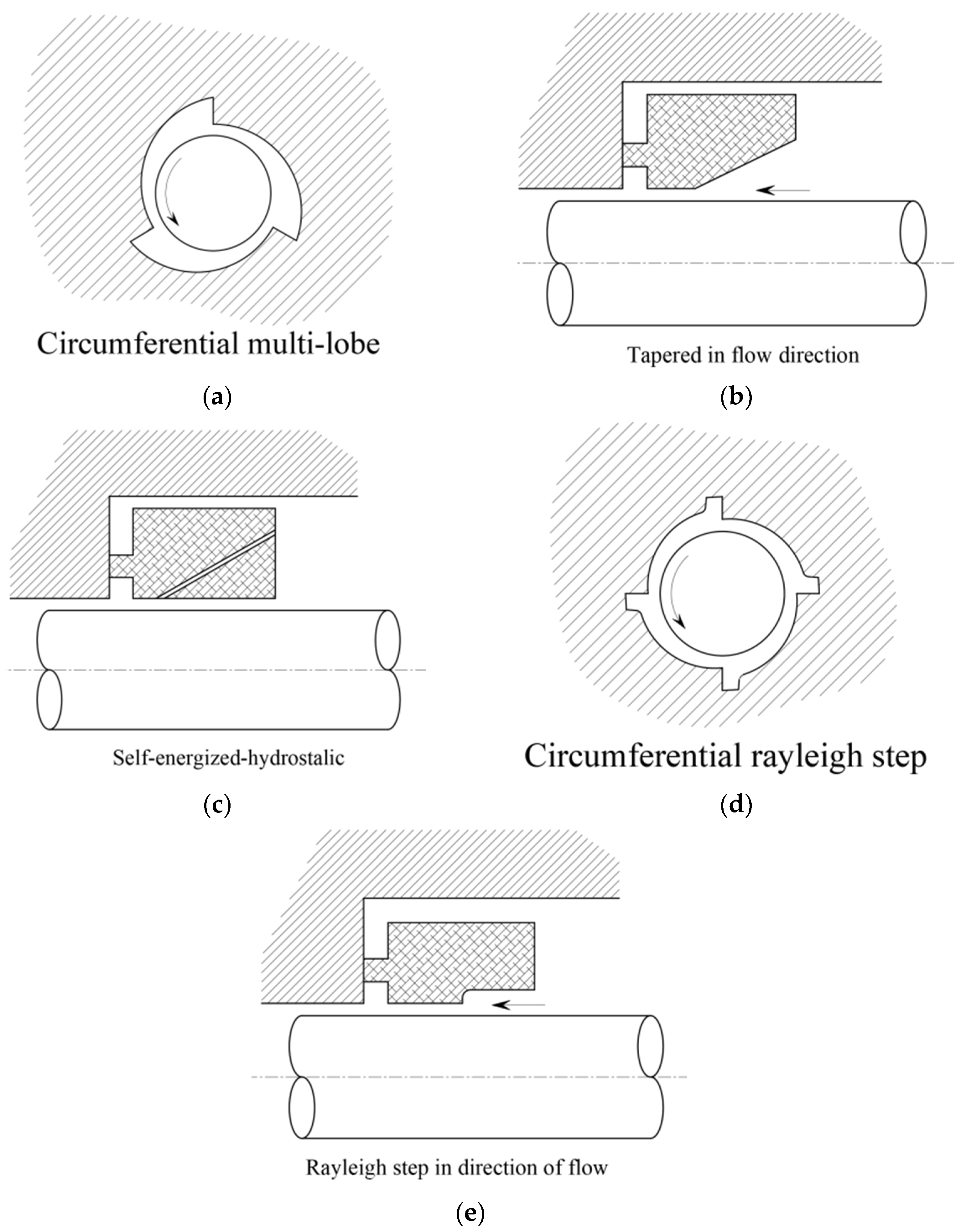
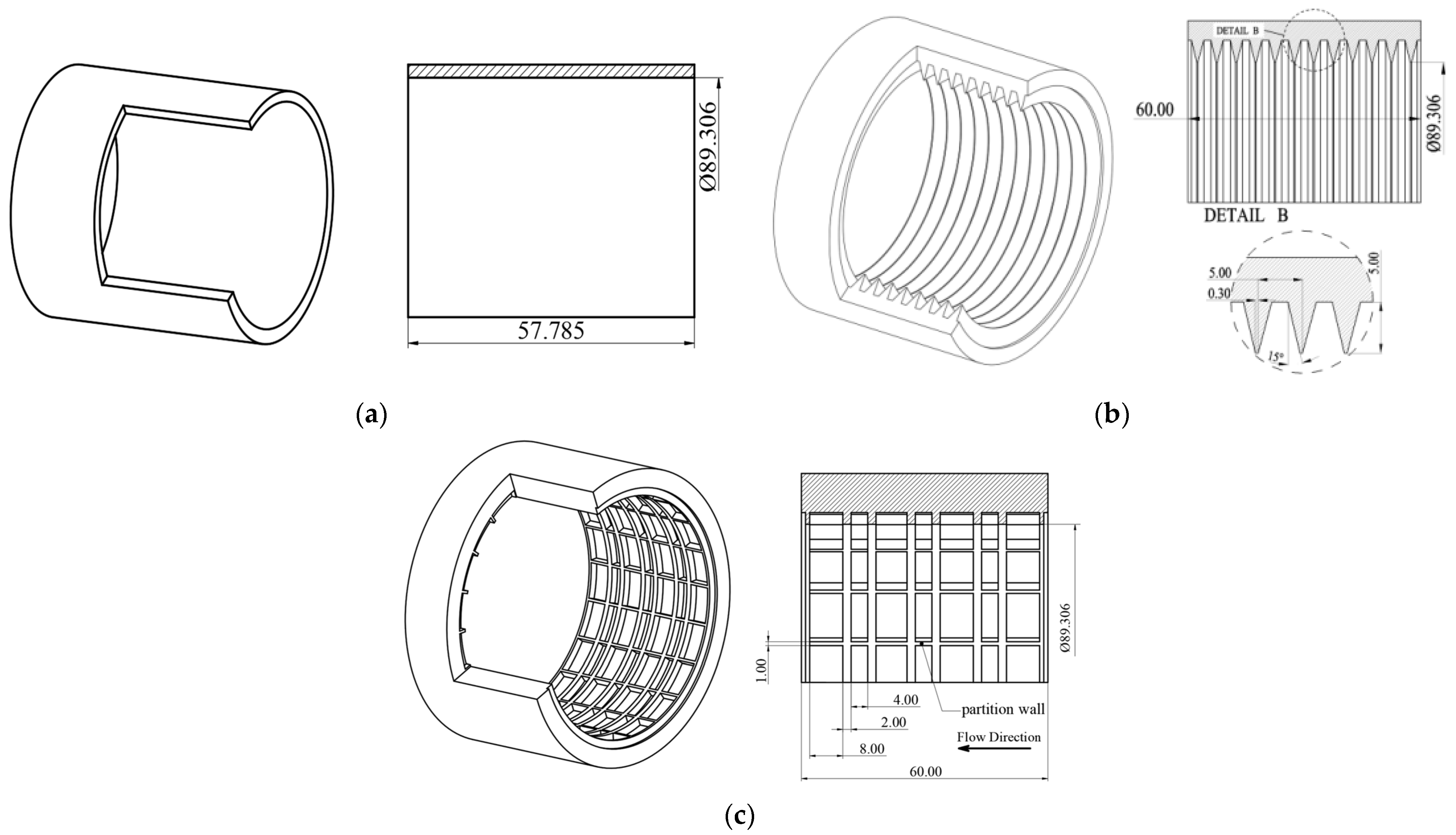
3.1. Structural Characteristics and Groove Structure of Cylindrical Gas Film Seal
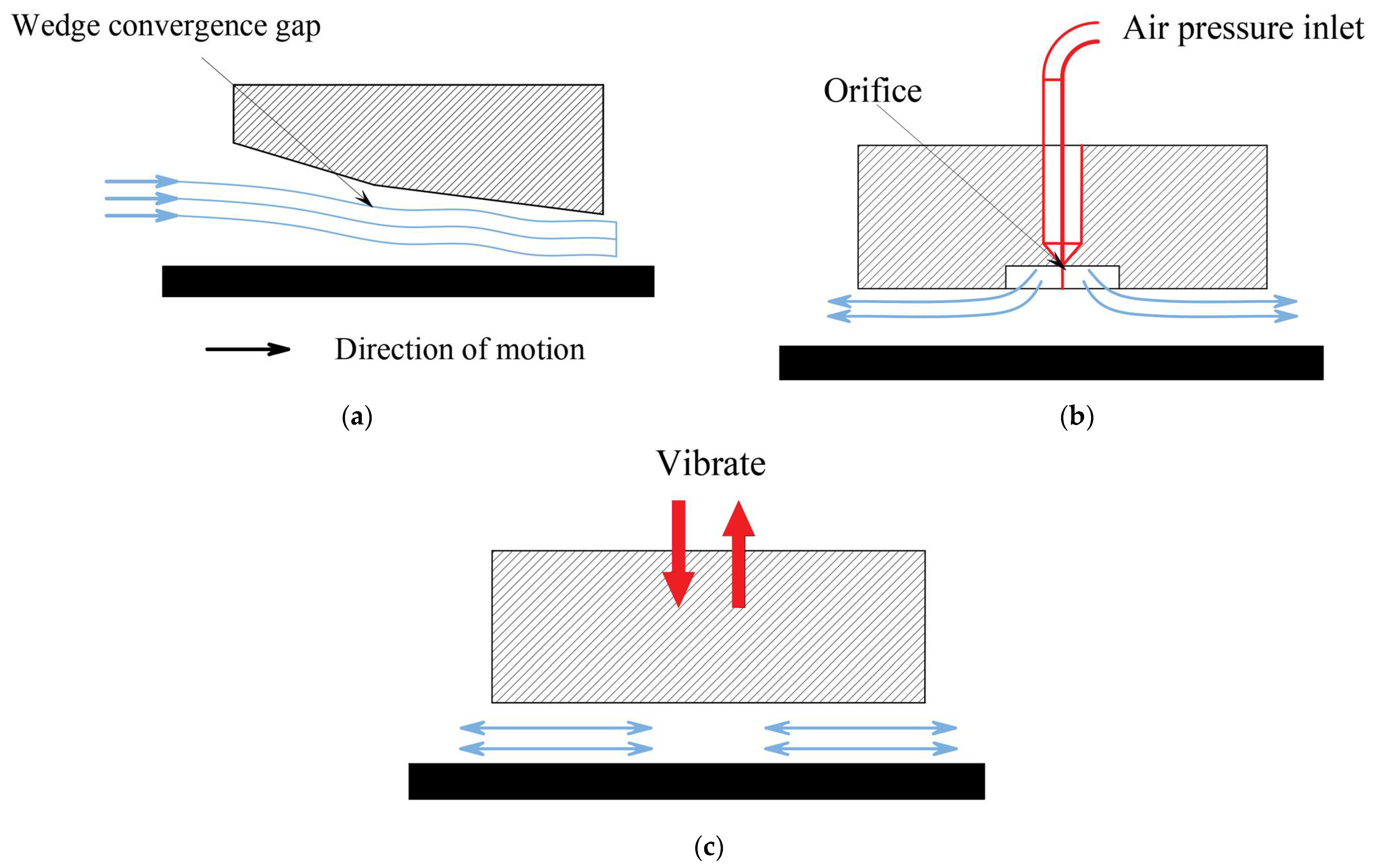
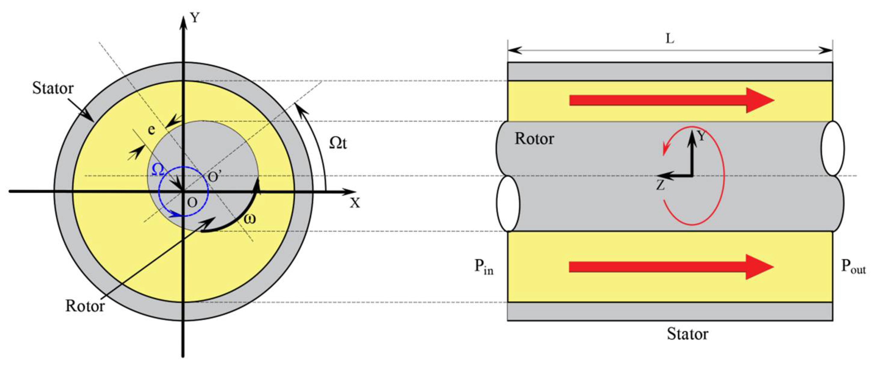
3.2. Working Principle of Cylindrical Gas Film Seal
4. Overview of the Development of a Typical Cylindrical Gas Film Seal Structure
- (1)
- From the overall system structure, through the design of the relevant elastic parts or floating parts, so that the system can have enough compliant support, this compliant support structure can absorb the vibration displacement of the rotor system, through the system’s being adaptive to ensure that there is enough gas film thickness, so that the gas film sealing maintains a non-contact state.
- (2)
- The structural form design should be fully considered, with an adaptive large compliant support structure form that should be easy to quantitatively design and undergo structural analysis.
4.1. Compliant Shaft Cylindrical Gas Film Seal Structure
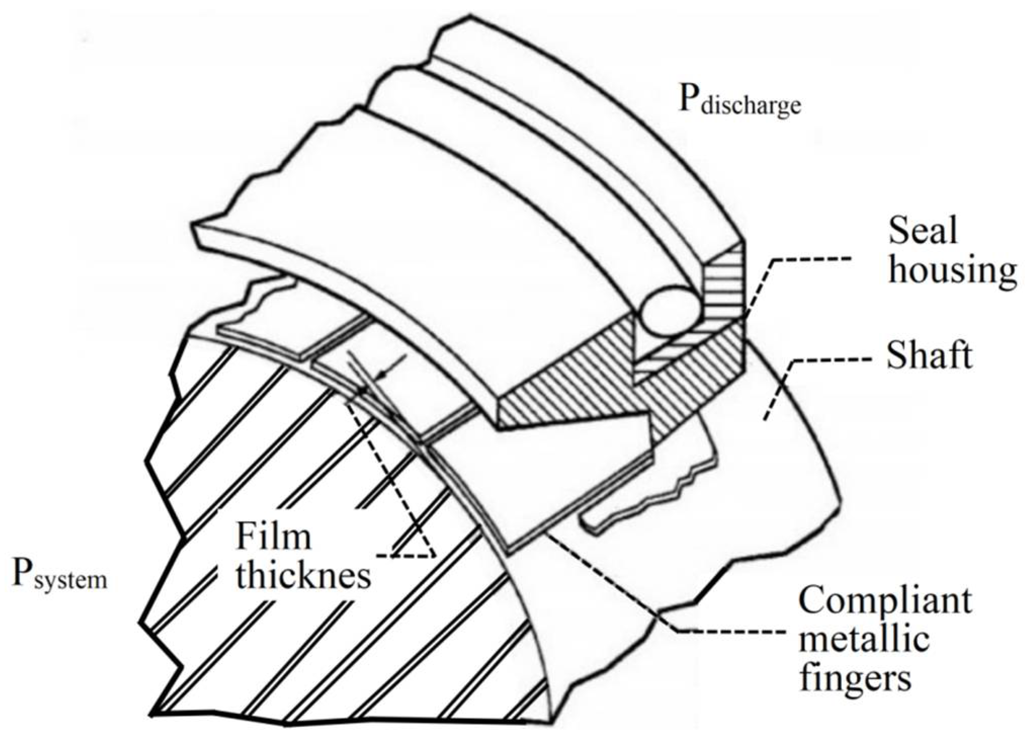
4.2. Compliant Foil Cylindrical Gas Film Seal Structures
4.3. Leaf and Wafer Seals
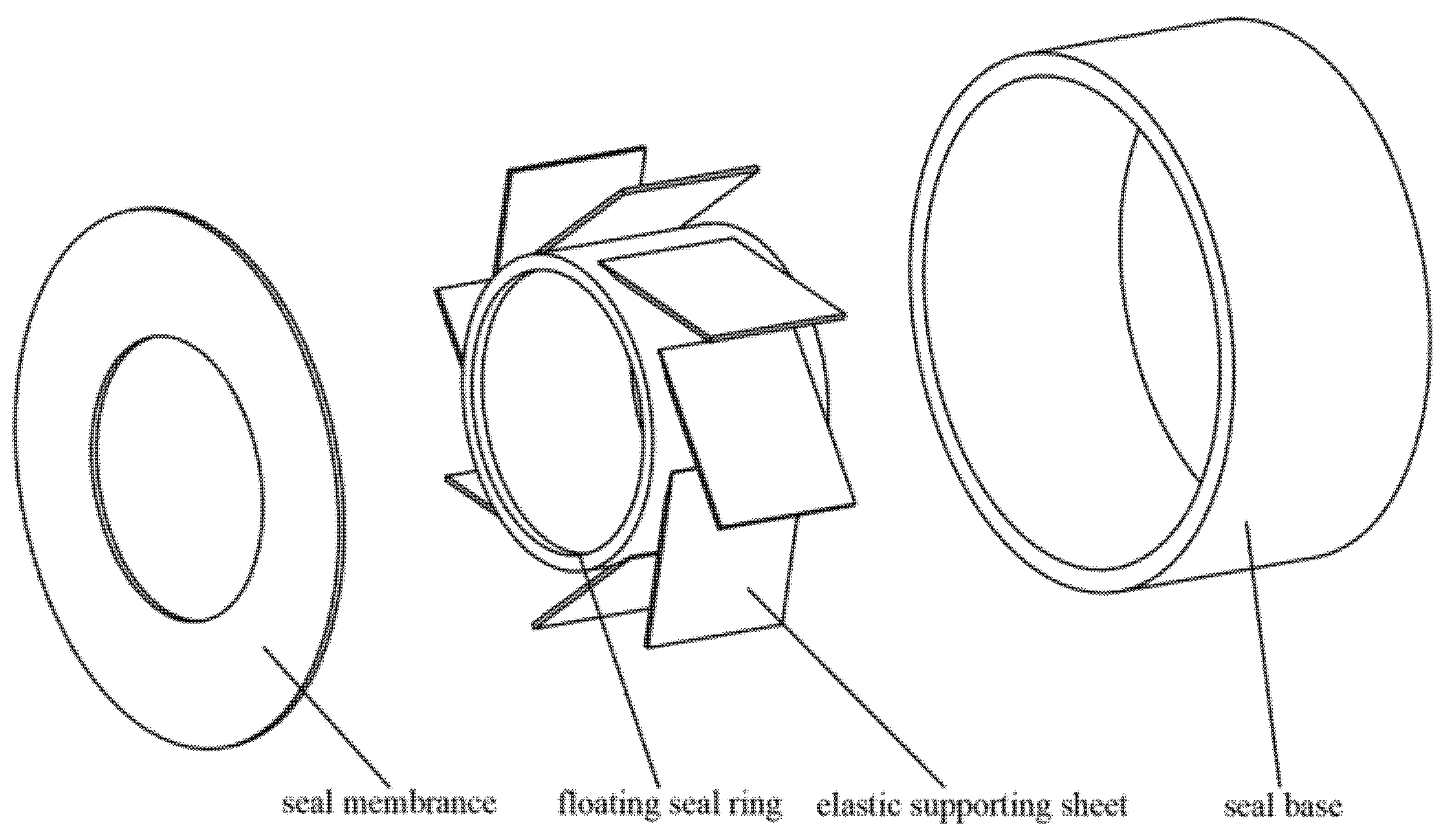
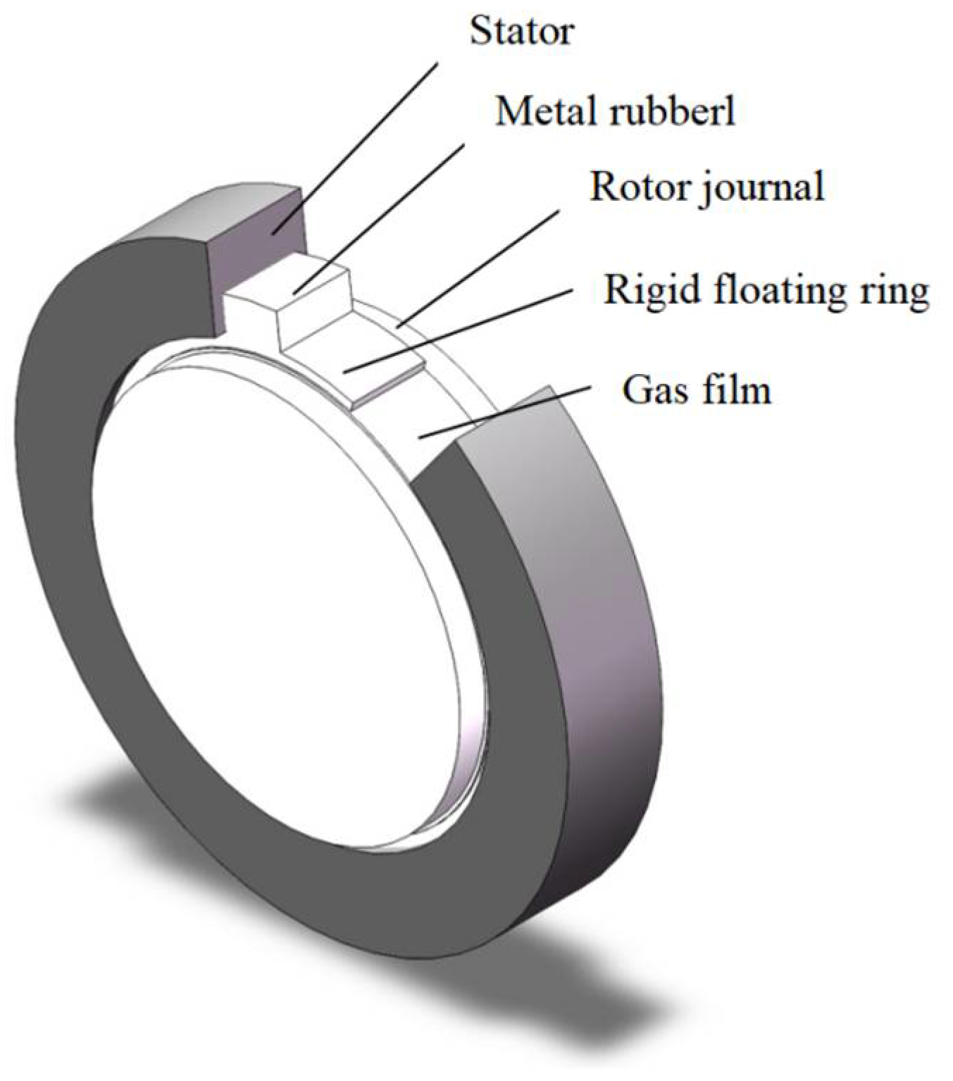
4.4. Other New Cylindrical Gas Film Seal Structures and Concepts
5. Research Methodology for Cylindrical Gas Film Seals
5.1. Main Research Methods
- (1)
- By establishing the geometric model of the cylindrical gas film seal, dividing the mesh, and simulating the flow field of the cylindrical gas film seal by using a finite element analysis software such as Fluent, the pressure distribution of the gas film on the sealing surface is derived, and then the performance changes of the seal structure and other aspects are investigated.
- (2)
- According to the operating conditions and assumptions of the seal, it is possible to establish an appropriate Reynolds equation [126], using the finite difference method, finite element method, analytical method, etc., to solve the calculation, to obtain the pressure distribution on the sealing surface, and then obtain the working condition parameters, structural parameters, etc., of the steady-state performance of the cylindrical gas film seal of the influence of the law. Similarly, it is possible, after perturbation of the Reynolds equation, to set up the solution to obtain the seal dynamic performance change rule.
- (1)
- The system of variational equations is composed of a steady-state equation and four mutually coupled perturbed linear equations, which must be solved by association, and the dynamic pressure in each perturbed equation is related to the perturbed frequency, which needs to be associated with the perturbed equations of motion of the sealing ring, and then solved by a numerical iteration method.
- (2)
- The solution domain is divided into triangular cells, the cells and nodes are numbered sequentially, and the nodes to be solved are numbered preferentially; the number of boundary nodes is recorded first and then introduced point by point according to the boundary conditions; according to the structural form of the sealing interface, attention is paid to the slots and platforms boundaries falling on the boundaries of the cell mesh.
5.2. Establishment and Solution of the Reynolds Equation
- (1)
- The gas lubrication is a Newtonian fluid, the effect of volume forces is neglected, and there is no sliding of the fluid on the solid interface.
- (2)
- In the direction along the thickness of the lubricating film, the change of pressure is not counted.
- (3)
- Neglect the change of velocity direction caused by the surface curvature.
- (4)
- The flow state is laminar, ignoring the effect of inertial force.
6. Progress in the Study of Stability, Dynamic Performance, and Multi-Physics Field Coupling of Cylindrical Gas Film Seal
6.1. Steady-State Performance Analysis of Cylindrical Gas Film Seals
6.2. Dynamic Characterization of Cylindrical Gas Film Seal
6.3. Multi-Physics Field Coupling and Structural Deformation Study of Cylindrical Gas Film Seals
6.4. Research on the Test and Processing Technology of Cylindrical Gas Film Sealing
7. Conclusions
Problems in the Study of Cylindrical Gas Film Seals and the Future Direction of Development
- (1)
- Along with the rapid development of industrial technology, aeroengines and other rotating machinery and equipment have put forward higher requirements for the sealing technology and sealing structure. Compared with the traditional labyrinth sealing, brush sealing, cellular sealing, and other aeroengine sealing technologies, gas film sealing, as a kind of non-contact sealing form with low leakage, low wear and tear, long service life, etc., has demonstrated great potential in the development of the aeroengine sealing technology. Since the concept of a gas film seal was put forward, through the continuous efforts of researchers, the end-face gas film seal has been successfully applied in all kinds of rotating machinery; however, the static “three highs” of the aeroengine and the dynamic strong vibration of the harsh conditions limit the engineering application of the gas film face seal, due to the large compliant structure of the cylindrical gas film seal, with a large axial degree of freedom, which can effectively reduce the friction and wear of the sealing structure due to the tilting of the rotor, and it has a very good prospect for application in the field of aeroengine sealing technology.
- (2)
- The compliant support structure of the cylindrical gas film seal is an important part of the sealing technology. Researchers have introduced compliant shafts, compliant foils, thin leaf plates, thin-walled beams, and other large compliant parts to increase the axial degree of freedom of the cylindrical sealing structure and to resist rotor vibration and inhomogeneous thermal deformation under the harsh conditions of aeroengines. Researchers proposed a new series of cylindrical gas film seal structures with a new form for solving the existing problems of aeroengine gas film seal structure ideas, but most of the compliant structures have quantitative design processing and manufacturing difficulties and other problems, so for the compliant support structure material selection and structure design, the gas film seal research needs to focus on the consideration.
- (3)
- Cylindrical gas film seal technology has been developed for decades, and researchers have made a lot of contributions to the structural design of cylindrical gas film seals. The existing research basis is mainly carried out based on the influence of steady-state performance, while the structural design method mostly adopts the control variable method and trial-and-error method, and less consideration is given to the multidimensional optimization algorithm and overall topology optimization. An aeroengine in actual operation needs to consider the dynamic characteristics, self-excited vibration of the gas film, and stability and other issues, so the design quantization of the cylindrical gas film seal structure needs a complete set of structural design theories.
- (4)
- Regarding the research on the steady dynamic performance and structural mechanism of the cylindrical gas film seal, with the deepening of the understanding of the sealing technology, the research on the dynamics of the gas film seal has been extended to include the unsteady-state dynamics, the linear dynamics of small perturbations, and the nonlinear dynamics and other aspects.
- (5)
- Due to the mutual influence of the pressure distribution, deformation, and temperature distribution in the gap of the sealing structure, it is crucial to analyze the heat–fluid–solid multi-physical field coupling of the gas film sealing structure. In the structural mechanism and multi-physical field coupling study of the gas film seal, based on the field synergy under the cylindrical seal behavior, research and performance prediction will be the focus of future research, the development of an aeroengine seal-specific multi-physical field coupling calculation method, in-depth understanding of the sealing structure and the working principle, to enhance the sealing structure of the independent design of innovation are the urgent needs of the field of cylindrical sealing technology.
- (6)
- With the deepening of sealing technology research for aviation engines, the continuous updating of sensors and the increasing accuracy of transmitters, coupled with the rapid development of computer-aided testing technology, the gas sealing test and testing technology is becoming more mature, in the future, seal test and evaluation based on an advanced and composite sensing technology will be the new direction, and sealing based on the new principles, new materials, and new structural innovations in the design of the seal will also shine.
Author Contributions
Funding
Conflicts of Interest
Nomenclature
| R | outer radius of the sleeve, m |
| θ | circumferential direction coordinate, rad |
| p | lubrication film pressure, Pa |
| h | thickness of the lubrication film, m |
| μg | the viscosity of the lubrication gas, N.s/m2 |
| T | temperature of the lubrication gas, °C |
| z | axial coordinate, m |
| ω | angular speed of the rotating shaft rotation, rad/s |
| t | running time, s |
References
- Braun, M.J.; Kudriavtsev, V.V.; Steinetz, B.M.; Proctor, M.P. Two- and Three-Dimensional Numerical Experiments Representing Two Limiting Cases of an In-Line Pair of Finger Seal Components. Int. J. Rotating Mach. 2002, 9, 171–179. [Google Scholar] [CrossRef]
- Povinelli, V.P. Current seal designs and future requirements for turbine engine seals and bearings. J. Aircr. 1975, 12, 266–273. [Google Scholar] [CrossRef]
- Shu, L.J.; Bo, C.Z. Prospects of Aeroengine Power Transmission System in the 21st Century. J. Aerosp. Power 2001, 16, 108–114. [Google Scholar]
- Steinetz, B.M.; Hendricks, R.C.; Munson, J. Advanced Seal Technology Role in Meeting Next Generation Turbine Engine Goals; RTO AVT Symposium: Toulouse, France, 1999. [Google Scholar]
- Guang-Yang, H.U. Application Research of Seal Technologies for Aeroengine. Aeroengine 2012, 38, 1–4. [Google Scholar]
- Shen, X.; Liu, Y.; Ma, G. Tribology for Aero-Gas Turbine Engine, 1st; Beihang University Press: Beijing, China, 2008. [Google Scholar]
- Sayma, A.I.; Bré Ard, C.; Vahdati, M.; Imregun, M. Aeroelasticity Analysis of Air-Riding Seals for Aero-Engine Applications. J. Tribol. 2002, 124, 607–616. [Google Scholar] [CrossRef]
- Li, J.; Yan, X.; Li, Z. Thermal Turbine Seal Technology, Xi’an Jiaotong University Press: Xi’an, China, 2016.
- Chen, G. Aero-Engine Structural Design Analysis, 2nd ed.; Beihang University Press: Beijing, China, 2006. [Google Scholar]
- Lin, Z. Gas Dynamics; Beihang University Press: Beijing, China, 1988. [Google Scholar]
- Dogu, Y.; Sertçakan, M.C.; Gezer, K.; Kocagül, M.; Arican, E.; Ozmusul, M.S. Labyrinth Seal Leakage Degradation Due to Various Types of Wear. J. Eng. Gas Turbines Power-Trans. Asme 2017, 139, 062504. [Google Scholar] [CrossRef]
- Martin, H.M. Labyrinth packings. Engineering 1908, 85, 35–38. [Google Scholar]
- Chupp, R.E.; Hendricks, R.C.; Lattime, S.B.; Steinetz, B.M. Sealing in Turbomachinery. J. Propuls. Power 2006, 22, 313–349. [Google Scholar] [CrossRef]
- Chupp, R.E.; Ghasripoor, F.; Turnquist, N.A.; Demiroglu, M.; Aksit, M.F. Advanced Seals for Industrial Turbine Applications: Dynamic Seal Development. J. Propuls. Power 2002, 18, 1260–1266. [Google Scholar] [CrossRef]
- Alford, J.S. Labyrinth Seal Designs Have Benefitted from Development and Service Experience. In SAE Technical Paper 710435; SAE International: Warrendale, PA, USA, 1971; Volume 1, 13p. [Google Scholar]
- Ghasripoor, F.; Turnquist, N.A.; Kowalczyk, M.; Couture, B. Wear Prediction of Strip Seals Through Conductance. In Proceedings of the 2004 ASME Turbo Expo, Vienna, Austria, 14–17 June 2004. [Google Scholar]
- Xu, J.M.; Ambrosia, M.S.; Rhode, D.L. Effect of tooth bending damage on the leakage of straight-through labyrinth seals. In Proceedings of the 2005 ASME Fluids Engineering Division Summer Meeting, New York, NY, USA, 19–23 June 2005. [Google Scholar]
- Xu, J. Effects of Operating Damage of Labyrinth Seal on Seal Leakage and Wheelspace Hot Gas Ingress. Ph.D. Thesis, Texas A&M University, College Station, TX, USA, 2006. [Google Scholar]
- Cangioli, F.; Chatterton, S.; Pennacchi, P.; Nettis, L.; Ciuchicchi, L. Thermo-elasto bulk-flow model for labyrinth seals in steam turbines. Tribol. Int. 2018, 119, 359–371. [Google Scholar] [CrossRef]
- Zhang, X. The Numerical Analysis of The Influence on Aerodynamic Performance by Large Steam Turbine Labyrinth Seal Structure. Master’s Thesis, Tsinghua University, Beijing, China, 2014. [Google Scholar]
- Li, Z.; Lang, J.; Li, J.; Feng, Z. Experiment on Leakage Flow Characteristics of Labyrinth Seal. J. Xi’an Jiaotong Univ. 2011, 45, 48–52, 64. [Google Scholar]
- Xu, L.; Wang, Z.; Xi, G. Numerical Study on Effect of Seal Leakage on Performance of Centrifugal Impeller with Low Flow Coefficient. J. Xi’an Jiaotong Univ. 2010, 44, 23–27. [Google Scholar]
- Sturgess, G.; Datta, P. Application of CFD to gas turbine engine secondary flow systems—The labyrinth seal. In Proceedings of the 24th Joint Propulsion Conference, Boston, MA, USA, 11–13 July 1988. [Google Scholar]
- Abbott, D.R. Advances in Labyrinth Seal Aeroelastic Instability Prediction and Prevention. J. Eng. Power 1981, 103, 308–312. [Google Scholar] [CrossRef]
- Kanki, H.; Shibabe, S.; Goshima, N. Destabilizing Force of Labyrinth Seal Under Partial Admission Condition. In Proceedings of the International Symposium on Stability Control of Rotating Machinery, Gdansk, Poland, 4–8 August 2003. [Google Scholar]
- Trutnovsky, K. Contactless Seals, Foundations and Applications of Flows Through Slots and Labyrinths. NASA TT F 1977, 17, 352. [Google Scholar]
- Worthington, J.; Shaw, T.M.; Genter, D.; Richardson, D.E.; Mcgiffen, I.; Luehrmann, M.G.; Gunter, K. Cylinder Liner Seal Arrangement and Method of Providing the Same. U.S. Patent 8,601,995, 10 December 2013. [Google Scholar]
- Ferguson, J. Brushes as high performance gas turbine seals. In Proceedings of the Turbo Expo: Power for Land, Sea, and Air, Philadelphia, PA, USA, 25–29 September 1988; p. V002T002A006. [Google Scholar]
- Bayley, F.J.; Long, C.A. A Combined Experimental and Theoretical Study of Flow and Pressure Distributions in a Brush Seal. J. Eng. Gas Turbines Power 1993, 115, 404–410. [Google Scholar] [CrossRef]
- Hendricks, R.; Steinetz, B.; Zaretsky, E.; Athavale, M.; Przekwas, A.; Tam, L.; Muszynska, A.; Braun, M. Reviewing Turbomachine Sealing and Secondary Flows Parts A, B, C. In Proceedings of the the 2nd International Symposium on Stability Control of Rotating Machinery, ISCORMA-2003, Gdansk, Poland, 4–8 August 2003; pp. 40–91. [Google Scholar]
- Holle, G.; Krishnan, M. Gas turbine engine brush seal applications. In Proceedings of the 26th Joint Propulsion Conference, Orlando, FL, USA, 16–18 July 1990. [Google Scholar]
- Bhate, N.; Thermos, A.C.; Aksit, M.F.; Demiroglu, M.; Kizil, H. Non-metallic brush seals for gas turbine bearings. In Proceedings of the Asme Turbo Expo: Power for Land, Sea, & Air, Vienna, Austria, 14–17 June 2004. [Google Scholar]
- Franceschini, G.; Jones, T.V.; Gillespie, D.R.H. Improved Understanding of Blow-Down in Filament Seals. J. Turbomach. 2008, 132, 041004. [Google Scholar] [CrossRef]
- Basu, P.; Datta, A.; Loewenthal, R.; Short, J.; Johnson, R. Hysteresis and bristle stiffening effects in brush seals. J. Propuls. Power 1994, 10, 569–575. [Google Scholar] [CrossRef]
- Chew, J.W.; Hogg, S.I. Porosity modeling of brush seals. J. Tribol. 1997, 119, 769–775. [Google Scholar] [CrossRef]
- Sun, D.; Liu, N.; Hu, G.; Ai, Y.; Wang, K. Fluid-structure interaction investigation on the flow field and mechanical characteristic in brush seals with bristle deflections. J. Aerosp. Power 2016, 31, 2544–2553. [Google Scholar]
- Huang, X. A Numerical Study of Leaksge Flow and Heat Transfer in A Brush Seal. Ph.D. Thesis, Beihang University, Beijing, China, 1999. [Google Scholar]
- Dinc, S.; Demiroglu, M.; Turnquist, N.; Mortzheim, J.; Florin, M. Fundamental Design Issues of Brush Seals for Industrial Applications. J. Turbomach. 2002, 124, 293–300. [Google Scholar] [CrossRef]
- Chen, L.; Wood, P.; Jones, T.; Chew, J. Detailed experimental studies of flow in large scale brush seal model and a comparison with CFD predictions. J. Eng. Gas Turbines Power 2000, 122, 672–679. [Google Scholar] [CrossRef]
- Dogu, Y.; Aksit, M.F. Brush Seal Temperature Distribution Analysis. J. Eng. Gas Turbines Power 2006, 128, 599–609. [Google Scholar] [CrossRef]
- Deville, L.; Arghir, M. Theoretical Analysis of Brush Seals Leakage Using Local Computational Fluid Dynamics Estimated Permeability Laws. J. Eng. Gas Turbines Power-Trans. Asme 2018, 140, 062803. [Google Scholar] [CrossRef]
- Raben, M.; Friedrichs, J.; Flegler, J.; Helmis, T. Brush Seals Used in Steam Environments—Chronological Wear Development and the Impact of Different Seal Designs. J. Eng. Gas Turbines Power 2015, 138, 051901. [Google Scholar] [CrossRef]
- Zhang, Y.; Wang, Y.; Yan, X.; Li, J. Investigations on the Leakage and Heat transfer Characteristics of Brush Seal Part 1: Leakage Characteristics. J. Eng. Thermophys. 2017, 38, 482–489. [Google Scholar]
- Zhang, Y.; Wang, S. Research and Application of Honeycomb Seal and Turbine Related Energy Saving Technology; China Electric Power Press: Beijing, China, 2007. [Google Scholar]
- Yao, J. Study on Principle and Technique of the Preparation of Aluminum Honeycomb Structure by Middle Temperature Precision Self-Brazing Process. Master’s Thesis, Tianjin University, Tianjin, China, 2014. [Google Scholar]
- Xiang, Z. Study on the Application of Honeycomb Sea Technology in Steam Turbine for Refining Unit. Master’s Thesis, East China University of Science and Technology, Shanghai, China, 2017. [Google Scholar]
- Vannini, G.; Mazzali, C.; Underbakke, H. Rotordynamic Computational and Experimental Characterization of a Convergent Honeycomb Seal Tested with Negative Preswirl, High Pressure With Static Eccentricity and Angular Misalignment. J. Eng. Gas Turbines Power-Trans. Asme 2017, 139, 052502. [Google Scholar] [CrossRef]
- Fischer, T.; Welzenbach, S.; Meier, F.; Werner, E.; Kyzy, S.U.; Munz, O. Modeling the rubbing contact in honeycomb seals. Contin. Mech. Thermodyn. 2018, 30, 381–395. [Google Scholar] [CrossRef]
- Gardner, J.F. Rotary Mechanical Seal of the Gap Type. US3499653A, 10 March 1970. [Google Scholar]
- Saxena, M.N. Dry gas seals and support systems: Benefits and options. Hydrocarb. Process. 2003, 82, 37–41. [Google Scholar]
- Kolomoets, A.; Dotsenko, V. Experimental Investigation «Dry» Gas-Dynamic Seals Used for Gas-Compressor Unit. Procedia Eng. 2012, 39, 379–386. [Google Scholar] [CrossRef]
- Krivshich, N.G.; Pavlyuk, S.A.; Deineka, A.V.; Kolesnik, S.A. Introduction and use of dry gas seal systems on ammonia plant compressors. Chem. Pet. Eng. 2003, 39, 608–611. [Google Scholar] [CrossRef]
- Gruenewald, M.; Wagner, W. Recent progress in compressor sealing. Seal. Technol. 2005, 2005, 6–8. [Google Scholar] [CrossRef]
- Group, H.P. Consider dry gas seals for centrifugal compressors. Hydrocarb. Process. 2005, 84, 9–11. [Google Scholar]
- Ding, X.; Zhang, W.; Yu, S.; Han, M.; Zhai, X. Dry Gas Seal Dynamics; China Machine Press: Beijing, China, 2015. [Google Scholar]
- Chen, G. Aeroengine Structure Design Analysis; Beijing University of Aeronautics and Astronautics Press: Beijing, China, 2014; pp. 85–96. [Google Scholar]
- Schweiger, F.A. The Performance of Jet Engine Contact Seals. Lubr. Eng. 1963, 6, 232–238. [Google Scholar]
- Jiang, J.; Peng, X.; Bai, S.; Li, J.; Chen, Y. Performance Analysis and Selection of a Bionic Bird Wing Multi—Array Spiral Groove Dry Gas Seal. Tribology 2015, 35, 274–281. [Google Scholar]
- Ding, X.; Zhang, G.; Huang, Y.; Zheng, J. Numerical Simulation of Computational Fluid Dynamics (CFD) of the Micro-Scale Flow Field in the Spiral Groove Dry Gas Seals. Chem. Eng. Mach. 2008, 36, 287–290. [Google Scholar]
- Ding, X. The Research on Steady-state and Dynamical Characterization of Lubricating Gaseous Film in the Spiral Grooved Gas Seals. Ph.D. Thesis, Lanzhou University of Technology, Lanzhou, China, 2008. [Google Scholar]
- Ding, X.; Pu, J.; Han, M.; Zhang, W.; Yu, S. Calculation and Analysis of Gas Film Stiffness in the Spiral Groove Gas Seal Based on the Second Order Slip Boundary. Chin. J. Mech. Eng. 2011, 47, 119–124. [Google Scholar] [CrossRef]
- Dini, D. Self active pad seal application for high pressure engines. In Proceedings of the AGARD Conference Proceedings No. 237—Seal Technology in Gas Turbine Engines, London, UK, 6–7 April 1978. [Google Scholar]
- Lu, J.; Zhang, W.; Xie, F.; Jiao, Y. Performance analysis of gas film of adaptive cylindrical seal. CIESC J. 2020, 71, 346–354. [Google Scholar] [CrossRef]
- Ma, G.; Xu, G.; Shen, X. Design and Analysis for Spiral Grooved Cylindrical Gas Seal Structural Parameter. Lubr. Eng. 2007, 32, 127–130. [Google Scholar]
- Ma, G.; Li, X.; Shen, X.; Hu, G. Analysis of performance and interface structure of cylinder gas film seal. J. Aerosp. Power 2011, 26, 2610–2616. [Google Scholar]
- Wang, Y. Gas Lubricated Theory and Design Manual of Gas Bearings; China Machine Press: Beijing, China, 1999. [Google Scholar]
- Gardner, J.; Basu, P.; Dutta, A. A New Compliant Seal Concept for Aerospace Applications. In Proceedings of the Fourth International Symposium on Transport Phenomena and Dynamics of Rotating Machinery, Honolulu, HI, USA, 5–8 April 1992; pp. 593–612. [Google Scholar]
- Athavale, M.; Przekwas, A. Numerical, Analytical, Experimental Study of Fluid Dynamic Forces in Seals Volume 6: Description of Scientific CFD Code SCISEAL; NASA: Washington, DC, USA, 2004.
- Steinetz, B.M.; Hendricks, R.C. Engine seal technology requirements to meet NASA’s Advanced Subsonic Technology program goals. J. Propuls. Power 1994, 12, 786–793. [Google Scholar] [CrossRef]
- Hsing, F.C.; Carrano, M.J. Analysis of Compressible Fluid Flow in Gas Turbine Mainshaft Seals. ASLE Trans. 1980, 23, 237–243. [Google Scholar] [CrossRef]
- Nakane, H.; Maekawa, A.; Akita, E.; Akagi, K.; Nakano, T.; Nishimoto, S.; Hashimoto, S.; Shinohara, T.; Uehara, H. The Development of High-Performance Leaf Seals. J. Eng. Gas Turbines Power. 2004, 126, 342–350. [Google Scholar] [CrossRef]
- Salehi, M.; Heshmat, H. Performance of a Complaint Foil Seal in a Small Gas Turbine Engine Simulator Employing a Hybrid Foil/Ball Bearing Support System. Tribol. Trans. 2001, 44, 458–464. [Google Scholar] [CrossRef]
- Bidkar, R.A.N.; Giametta, A.P.; Gibson, N.E.M.; Cleveland, N.J. Film Riding Seal Assembly for Turbomachinery. US9359908B2, 7 June 2016. [Google Scholar]
- Bidkar, R.A.N.; Thatte, A.M.; Gibson, N.E.M.; Giametta, A.P. Pressure Actuated Film Riding Seals for Turbo Machinery. US9115810B2, 25 August 2015. [Google Scholar]
- Gibson, N.E.M.C.; Bidkar, R.A.; Thatte, A.M.; Shastry, N.; Hariharan, M.S. Flexible Film-Riding Seal. U.S. Patent No. 10,161,259, 25 December 2018. [Google Scholar]
- Justak, J.F.S. Hydrodynamic Brush Seal. US7182345B2, 27 February 2007. [Google Scholar]
- Salehi, M.; Heshmat, H.; Walton, J.; Cruzen, S. The application of foil seals to a gas turbine engine. In Proceedings of the 35th Joint Propulsion Conference and Exhibit, Los Angeles, CA, USA, 20–24 June 1999; p. 2821. [Google Scholar]
- Salehi, M.; Heshmat, H. Non-Contacting Compliant Foil Seal for Gas Turbine Engine. In Proceedings of the 2001 NASA Seal/Secondary Air System Workshop, Cleveland, OH, USA, 30–31 October 2001; Volume 1, pp. 187–207. [Google Scholar]
- Heshmat, H.N. Compliant Foil Seal. US6505837B1, 14 January 2003. [Google Scholar]
- Salehi, M.; Heshmat, H. High temperature performance evaluation of a compliant foil seal. In Proceedings of the 36th AIAA/ASME/SAE/ASEE Joint Propulsion Conference and Exhibit, Huntsville, AL, USA, 17–19 July 2000; p. 3376. [Google Scholar]
- Salehi, M.; Heshmat, H. Evaluation of Large Compliant Gas Foil Seals Under Engine Simulated Conditions. In Proceedings of the 38th AIAA/ASME/SAE/ASEE Joint Propulsion Conference & Exhibit, Indianapolis, IN, USA, 7–10 July 2002; p. 3792. [Google Scholar]
- Proctor, M.; Delgado, I. Compliant Foil Seal Investigations; NASA: Washington, DC, USA, 2004.
- Munson, J.; Grant, D.; Agrawal, G. Foil face seal development. In Proceedings of the 37th Joint Propulsion Conference and Exhibit, Salt Lake City, UT, USA, 8–11 July 2001; p. 3483. [Google Scholar]
- Heshmat, H.; Walton, J. Innovative High-Temperature Compliant Surface Foil Face Seal Development. In Proceedings of the 44th AIAA/ASME/SAE/ASEE Joint Propulsion Conference & Exhibit, Hartford, CT, USA, 21–23 July 2008. [Google Scholar]
- Munson, J. Foil face seal testing. In Proceedings of the 2008 NASA Seal/Secondary Air System Workshop, Cleveland, OH, USA, 14–15 November 2009. [Google Scholar]
- Jahn, I.H.J.; Owen, A.K.; Franceschini, G.; Gillespie, D.R.H. Experimental characterisation of the stiffness and leakage of a prototype leaf seal for turbine applications. In Proceedings of the 53rd ASME Turbo Expo 2008, Berlin, Germany, 9–13 June 2008; pp. 1657–1666. [Google Scholar]
- Salehi, M.; Heshmat, H. On the Fluid Flow and Thermal Analysis of a Compliant Surface Foil Bearing and Seal. Tribol. Trans. 2000, 43, 318–324. [Google Scholar] [CrossRef]
- Salehi, M.; Heshmat, H. Analysis of a compliant gas foil seal with turbulence effects. In Proceedings of the Joint Propulsion Conference & Exhibit, San Jose, CA, USA, 15–17 July 2013. [Google Scholar]
- Kim, K.W.; Chung, J.T.; Kim, C.H.; Lee, Y.B. Theoretical research of Static Characteristics of Bump Floating Ring Seal. J. Korean Soc. Tribol. Lubr. Eng. 2008, 24, 140–146. [Google Scholar]
- Lee, Y.B.; Kim, K.W.; Ryu, S.J.; Chung, J.T. Leakage Performance and Rotordynamic Characteristics of Bump Floating Ring Seals for Turbopump. In Proceedings of the ASME Turbo Expo: Turbine Technical Conference and Exposition, Dusseldorf, Germany, 16–20 June 2014. [Google Scholar]
- Raghuraman, S. Performance Evaluation of Compliant Foil Seal. Master’s Thesis, The University of Texas at Arlington, Arlington, TX, USA, 2015. [Google Scholar]
- Peng, X.; Zhang, X.; Jiang, J.; Meng, X. A Flexible Foil Honeycomb Sealing Structure with Adjustable Sealing Gap. CN110469370A, 19 November 2019. [Google Scholar]
- Kang, Y.; Xu, D.; Liu, M.; Wang, J. An Elastic Wave Foil Type Column Surface Air Film Flexible Support Structure. CN21436752U, 8 October 2021. [Google Scholar]
- Kang, Y.; Li, X.; Liu, M. A Bubble-Type Foil Flexible Support of the Column Surface Air Film Seals. CN21436751U, 8 October 2021. [Google Scholar]
- Wang, X.; Liu, M.; Kao-Walter, S.; Hu, X. Numerical Evaluation of Rotordynamic Coefficients for Compliant Foil Gas Seal. Appl Sci 2020, 10, 3828. [Google Scholar] [CrossRef]
- Wang, X.; Liu, M.; Kang, Y.; Sun, J. Structural parameter analysis of flexible foil gas film seal. In Proceedings of the 13th National Conference on Gas Lubrication and Dry Gas Seals, Chengdu, China, 19 December 2020. [Google Scholar]
- Xu, D.; Liu, M.; Sun, J.; Zhao, C. Two-parameter Fitting Optimization Analysis of Gas Film on Grooved Cylindrical Surface. Agric. Equip. Veh. Eng. 2022, 60, 60–64+87. [Google Scholar]
- Wei, Q. Investigation into T-Groove Cylindrical Gas Film Flow and Thermal Mechanical Coupling of Flexible System. Master’s Thesis, Kunming University of Science and Technology, Kunming, China, 2021. [Google Scholar]
- Zhao, C. Fluid-Solid Coupling Analysis of Gas Film Seal on T-Slot Cylindrical Surface with Bubbling Support. Master’s Thesis, Kunming University of Science and Technology, Kunming, China, 2021. [Google Scholar]
- Chen, S. Study on Flow Mechanism and Characteristics of Steam Foil Seal Gap. Master’s Thesis, Harbin Institute of Technology, Harbin, China, 2021. [Google Scholar]
- Wang, X.; Liu, M.; Xiong, Z.; Li, X. Turbulence characteristics of compliant foil gas seal considering surface roughness. CIESC J. 2022, 73, 1683–1694. [Google Scholar]
- Sun, J.F.; Liu, M.H.; Xu, Z.; Liao, T.H.; Hu, X.P.; Li, Y.X.; Wang, J. Coupled Fluid-Solid Numerical Simulation for Flow Field Characteristics and Supporting Performance of Flexible Support Cylindrical Gas Film Seal. Aerospace 2021, 8, 97. [Google Scholar] [CrossRef]
- Xu, J.; Yu, S.; Ding, X.; Jiang, H.; Ding, J. Analysis of floating foil gas seal performance based on bump foil deformation. CIESC J. 2022, 73, 2083–2093. [Google Scholar] [CrossRef]
- Xun, J.; Yu, S.; Yang, X.; Ding, X.; Jiang, H. Impact Analysis of Surface Morphology on Floating Foil Film Sealing Performance. Tribology 2023, 43, 1341–1352. [Google Scholar]
- Shinohara, T.T.; Akagi, K.; Masanori, Y.; Masahiko, T.; Yutaka, O.; Akihiro, K.; Setunori, S.; Zenichi, Y.; Nobuhiro, K.; Takahiro, O.; et al. Shaft Seal and Turbine Using the Same. US6343792B1, 5 February 2002. [Google Scholar]
- Flower, R.F.J.B. Brush seal with asymmetrical elements. US5135237A, 4 August 1992. [Google Scholar]
- Steinetz, B.M.; Sirocky, P.J. High Temperature, Flexible Pressure-Actuated, Brush Seal. US5076590A, 31 December 1991. [Google Scholar]
- Hendricks, R.C.; Braun, M.J.; Canacci, V.; Mullen, R.L. Paper IX (i) Brush Seals in Vehicle Tribology. Tribol. Ser. 1991, 18, 231–242. [Google Scholar]
- Hendricks, R.C.; Schlumberger, S.; Braun, M.J.; Choy, F.; Mullen, R.L. A Bulk Flow Model of a Brush Seal System. Am. Soc. Mech. Eng. 1991, 78989, V001T001A099. [Google Scholar]
- Steinetz, B.M.; Hendricks, R.C. Aircraft Engine Seals. In Tribology for Aerospace Applications, Zaretsky, E.V., Ed.; STLE SP37 Society of Tribologists and Lubrication Engineers: Park Ridge, FL, USA, 1997. [Google Scholar]
- Nakane, H.; Maekawa, A.; Akita, E.; Akagi, K.; Shinohara, T.; Uehara, H. The Development of High Performance Leaf Seals. In Proceedings of the ASME Turbo Expo 2002: Power for Land, Sea, and Air, Amsterdam, The Netherlands, 3–6 June 2002. [Google Scholar]
- Gardner, J. Pressure Balanced, Radially Compliant Non-Contact Shaft Riding Seal. In Proceedings of the NASA Seal/Secondary Flows Workshop, Cleveland, OH, USA, 9–10 November 2004; pp. 329–348. [Google Scholar]
- Grondahl, C.M.; Dudley, J.C. Film riding leaf seals for improved shaft sealing. In Proceedings of the ASME Turbo Expo 2010, Glasgow, UK, 14–18 June 2010; pp. 1293–1300. [Google Scholar]
- Hendricks, R.C. Straight Cylindrical Seal for High-Performance Turbomachines; NASA-TP-1850; NASA: Washington, DC, USA, 1987; Volume 87, pp. 23–26.
- Hendricks, R.C. Three-Step Cylindrical Seal for High-Performance Turbomachines; National Aeronautics and Space Administration: Washington, DC, USA, 1987.
- Walowit, J.; Shapiro, W. Numerical, Analytical, Experimental Study of Fluid Dynamic Forces in Seals; NASA/CR-2004-213199/VOL3; National Aeronautics and Space Administration: Washington, DC, USA, 2004.
- Su, H.; Hou, G.; Chen, D.; Tian, Y. A Kind of Flexible Column Surface Air Film Seal Structure for Double Rotor between Shafts. CN111350551B, 26 April 2022. [Google Scholar]
- Ma, G.; Shen, X.; Li, X.; Zhao, W.; Sun, X.; He, J. A Gas Column Face Seal with Cantilever Support and Spiral Groove. CN102758918B, 8 April 2015. [Google Scholar]
- Hou, G.; Su, H.; Chen, G.; Tian, Y. Performance analysis of compliant cylindrical intershaft seal. Science Progress 2020, 103, 0036850420941957. [Google Scholar] [CrossRef] [PubMed]
- Wang, H.; Hong, J.; Ma, Y. Steady-state properties of gas film seal damper used in a rotor system. J. Aerosp. Power 2012, 27, 190–197. [Google Scholar]
- Hong, J.; Wang, H.; Ma, Y. Analysis on gas film stability performance of gas film seal damper. J. Beijing Univ. Aeronaut. Astronaut. 2011, 37, 6. [Google Scholar]
- Lu, J. Theoretical optimization and experiment on lubrication of floating microgroove cylindrical seal. Ind. Lubr. Tribol. 2020, 72, 1217–1226. [Google Scholar] [CrossRef]
- Ding, X.; Lu, J. Theoretical analysis and experiment on gas film temperature in a spiral groove dry gas seal under high speed and pressure. Int. J. Heat Mass Transf. 2016, 96, 438–450. [Google Scholar] [CrossRef]
- Ding, X.; Zhang, D.; Tang, D.; Zhang, W.; Bao, X. Design and test of new column surface gas film seal. J. Gansu Sci. 2019, 31, 97–101. [Google Scholar]
- Ding, X.; He, Z.; Zhang, W.; Lu, J.; Miao, C. Approximate calculation of steady micro-scale flow of cylindrical spiral groove dry gas seal. Chin. J. Appl. Mech. 2018, 35, 99–105. [Google Scholar]
- Ma, G.; Xun, W.; Xun, G.; Shen, X. A New Conception on Deduction of Reynolds Equation. Lubr. Eng. 2006, 36, 36–39+43. [Google Scholar]
- Whipple, R.T.P. Herringbone-Pattern Thrust Bearings; The National Archives: London, UK, 1949. [Google Scholar]
- Muijderman, E.A. Spiral groove bearings. Ind. Lubr. Tribol. 1965, 17, 12–17. [Google Scholar] [CrossRef]
- Lebeck, A.O. Principles and Design of Mechanical Face Seals; Wiley: Hoboken, NJ, USA, 1991. [Google Scholar]
- Liang, A.D.; Shapiro, W. Numerical, Analytical, Experimental Study of Fluid Dynamic Forces in Seals: Volume 2; Description of Gas Seal Codes GCYLT and GFACE; NASA: Washington, DC, USA, 2013.
- Mel’Nik, V.A. Calculation of the Characteristics of Seals with Floating Rings. Chem. Pet. Eng. 2013, 49, 542–548. [Google Scholar] [CrossRef]
- Khvorost, V.A.; Pryadko, S.V.; Mel’nik, V.A. Method of calculating floating seals. Vestn. Mashinostr. 1987, 6, 23–25. [Google Scholar]
- Mel’Nik, V.A. Calculation of the Radial Force in the Groove Seal of a Rotor with Stationary or Rotating Shaft. Chem. Pet. Eng. 2016, 52, 40–46. [Google Scholar] [CrossRef]
- Hirs, G.G. A Bulk-Flow Theory for Turbulence in Lubricant Films. ASME J. Lubr. Technol. 1973, 95, 146. [Google Scholar] [CrossRef]
- Nelson, C.C. Analysis for leakage and rotordynamic coefficients of surface-roughened tapered annular gas seals. J. Eng. Gas Turbines Power 1984, 106, 927–934. [Google Scholar] [CrossRef]
- Ha, T.W.; Childs, D.W. Annular Honeycomb-Stator Turbulent Gas Seal Analysis Using a New Friction-Factor Model Based on Flat Plate Tests. J. Tribol. 1994, 116, 895–899. [Google Scholar] [CrossRef]
- Jordan, L.T.; Wade, J. rotordynamic-coefficient and leakage characteristics for hole-pattern-stator annular gas seals-measurements versus predictions. Trans. ASME 2004, 126, 166–173. [Google Scholar]
- Chen, T.; Liu, M.H. Theory of Cylindrical Gas Film Seal. Appl. Mech. Mater. 2014, 602–605, 375–378. [Google Scholar] [CrossRef]
- Ma, G.; Zhao, W.; Shen, X. Analysis of parameters and performance for spiral grooved cylindrical gas film seal. Procedia Eng. 2011, 23, 115–119. [Google Scholar] [CrossRef]
- Li, G.; Zhang, Q.; Huang, E.; Lei, Z.; Wu, H.; Xu, G. Leakage performance of floating ring seal in cold/hot state for aero-engine. Chin. J. Aeronaut. 2019, 32, 2085–2094. [Google Scholar] [CrossRef]
- Zhao, X.; Yuan, S.H.; Wei, C. Influence of Fluid Slip on Operation Characteristics for High-Speed Spiral Groove Seal Ring. Tribol. Lett. 2018, 66, 49. [Google Scholar] [CrossRef]
- Zhang, G.-H.; Wang, G.-L.; Liu, Z.-S.; Ma, R.-X. Stability Characteristics of Steam Turbine Rotor Seal System with Analytical Floating Ring Seal Force Model. In Proceedings of the Turbo Expo: Power for Land, Sea, and Air, San Antonio, TX, USA, 3–7 June 2013; p. V07BT30A004. [Google Scholar]
- Zhang, W.-F.; Yang, J.-G.; Li, C.; Tian, Y.-W. Comparison of leakage performance and fluid-induced force of turbine tip labyrinth seal and a new kind of radial annular seal. Comput. Fluids 2014, 105, 125–137. [Google Scholar] [CrossRef]
- Andrés, L.S.; Ashton, Z. Comparison of Leakage Performance in Three Types of Gas Annular Seals Operating at a High Temperature (300 °C). Tribol. Trans. 2010, 53, 463–471. [Google Scholar] [CrossRef]
- Scharrer, J.K.; Rubin, N.; Nelson, C.C. The Effects of Fixed Rotor Tilt on the Rotordynamic Coefficients of Incompressible Flow Annular Seals. J. Tribol. 1993, 115, 336–340. [Google Scholar] [CrossRef]
- Scharrer, J.K.; Nelson, C.C. Rotordynamic Coefficients for Partially Roughened Pump Annular Seals. J. Vib. Acoust. 1991, 113, 240–244. [Google Scholar] [CrossRef]
- Su, Z.; Liu, M. CFD Numerical Simulation of Cylinder Gas Film Seal Properties. Lubr. Eng. 2016, 41, 49–53. [Google Scholar]
- Yu, S.; Ding, J.; Wang, S.; Liu, H.; Ding, X.; Sun, B. Simulation and analysis of dynamic pressure effect of gas film on cylinder seal. CIESC J. 2020, 71, 3220–3228. [Google Scholar]
- Ding, X.; Liu, H.; Wang, S.; Yan, R.; Xu, J. Study on Steady State Performance of Gas-Liquid Two-Phase Fluid Dynamic Pressure Seal in Spiral Groove of Cylinder. Lubr. Eng. 2022, 47, 22–29. [Google Scholar]
- Ding, X.; He, Z.; Zhang, W.; Lu, J.; Miao, C. Parameters analysis of steady micro-scale flow of cylindrical spiral groove dry gas seal. CIESC J. 2018, 69, 1537–1546. [Google Scholar]
- Ding, X.; Miao, C.; Zhang, W.; Lu, J. Numerical simulation of microscale flow field in dry gas seal with cylindrical spiral grooves. J. Lanzhou Univ. Technol. 2019, 45, 67–72. [Google Scholar]
- Wang, S.; Ding, X.; Lu, J.; Zhang, W.; Chen, J. Microscale Calculation and Experiment of Flow Field of Dry Gas Seal with Cylindrical Spiral Groove. Lubr. Eng. 2020, 45, 68–74. [Google Scholar]
- Wang, T.; Liu, M.; Sun, J.; Dai, D. Simulation Analysis of the Sealing Performance of Cylinder Gas Film. Fluid Mach. 2020, 48, 55–60. [Google Scholar]
- Dai, D.; Liu, M. CFD numerical analysis of flexible support cylindrical gas film seal. Electron. Sci. Technol. 2018, 31, 60–63, 67. [Google Scholar]
- Lu, J.; Zhang, W.; Ma, H. Floating performance of cylindrical microgroove gas floating seal based on F-K slip flow model. CIESC J. 2021, 72, 4267–4278. [Google Scholar]
- Sun, J.; Liu, M.; Li, Y.; Su, Z.; Kang, Y. Analysis on steady fluid dynamics of cylindrical gas seal by CFD. J. Drain. Irrig. Mach. Eng. 2017, 35, 968–974. [Google Scholar]
- Ma, G.; Sun, X.; He, J.; Shen, X. Simulation Analysis of Gas Face and Cylinder Film Seal by Parametric Modeling. Lubr. Eng. 2013, 38, 8–11. [Google Scholar]
- Ma, G.; Luo, X.; Shen, X. Numerical simulation and analysis of steady-state performances for face and cylinder gas film seal system. J. Aerosp. Power 2015, 30, 22–28. [Google Scholar]
- Ma, G.; Sun, X.; Luo, X.; He, J. Numerical simulation analysis of steady-state properties of gas face and cylinder film seal. J. Beijing Univ. Aeronaut. Astronaut. 2014, 40, 439–443. [Google Scholar]
- Chen, T.; Liu, M. Effects of Operating Parameters on the Seal Performance of Cylindrical Gas Film. Fluid Mach. 2014, 42, 43–46. [Google Scholar]
- Wei, Q.; Kang, Y.; Liu, M.; Sun, J. Numerical Study on Steady State Performance of T-Groove Cylindrical Gas Film Seal. Agric. Equip. Veh. Eng. 2022, 60, 5–9. [Google Scholar]
- Su, Z.; Liu, M. Numerical Simulation of Steady-state Properties of T Slot Cylinder Gas Film Seal. Mach. Electron. 2015, 12, 41–44. [Google Scholar]
- Su, Z.; Liu, M. CFD Numerical Simulation of T Slot Cylinder Gas Film Seal. Fluid Mach. 2016, 44, 33–37. [Google Scholar]
- Sun, D.; Wang, P.; Zhao, H.; Zhang, G.; Xiao, Z.; Meng, J. Numerical and experimental study on adaptive concentric performance of a new type of floating convergent pocket seal. Acta Aeronaut. Astronaut. Sin. 2020, 41, 423270. [Google Scholar]
- Sun, D.; Wang, P.; Wang, X.; Zhao, H.; Zhang, G. Investigation on Rotordynamic Characteristics and Adaptive Concentric Performance of a New Type of Floating Convergent Pocket Seal. J. Propuls. Technol. 2021, 42, 406–414. [Google Scholar]
- Ma, L.; Li, S.; Ma, Y.; Zhang, Q.; Cai, J. Analysis of Factors Influencing Characteristic Parameters of Gas Film Floating Ring Seal. Fluid Mach. 2018, 46, 6. [Google Scholar]
- Mu-ming, H.A.O.; Xian-xiao, Z.; Xiao-ning, C. Design and Analysis for Spiral Groove Gas Film Floating Ring Seal Structural Parameter. Fluid Mach. 2010, 38, 27. [Google Scholar]
- Balakh, L.Y.; Nikiforov, A.N. The reduction of the vibration level in high-speed rotor systems by means of floating seal rings. J. Mach. Manuf. Reliab. 2013, 42, 276–280. [Google Scholar] [CrossRef]
- Banakh, L.Y.; Barmina, O.V. The stability of rotation for a rotor with floating seal rings. J. Mach. Manuf. Reliab. 2015, 44, 114–119. [Google Scholar] [CrossRef]
- Banakh, L.Y.; Nikiforov, A.N. Aerohydrodynamic forces effect onto rapidly rotating rotary systems. Mekh Tverd. Tela 2005, 6, 130–139. [Google Scholar]
- Rui, X.; Yaoyu, H.; Junlian, Y.; Jiangtao, Z.; Dezhong, W. A transient CFD research on the dynamic characteristics of liquid annular seals. Ann. Nucl. Energy 2018, 120, 528–533. [Google Scholar]
- Ruan, B. Numerical Modeling of Dynamic Sealing Behaviors of Spiral Groove Gas Face Seals. J. Tribol. 2001, 124, 186–195. [Google Scholar] [CrossRef]
- Arghir, M.; Nguyen, M.H.; Tonon, D.; Dehouve, J. Analytic Modeling of Floating Ring Annular Seals. J. Eng. Gas Turbines Power 2012, 134, 153–161. [Google Scholar] [CrossRef]
- Yurko, V.; Martsynkovskyy, V. Influence of Changing the End Floating Seal Dynamic Characteristics on the Centrifugal Compressor Vibration State. Appl. Mech. Mater. 2013, 630, 356–364. [Google Scholar] [CrossRef]
- Arghir, M. Non-Linear Analysis of Floating Ring Annular Seals. In Proceedings of the International Joint Tribology Conference, Tallinn, Estonia, 18–19 October 2012; pp. 193–195. [Google Scholar]
- Ha, T.W.; Lee, Y.B.; Kim, C.H. Leakage and rotordynamic analysis of a high pressure floating ring seal in the turbo pump unit of a liquid rocket engine. Tribol. Int. 2002, 35, 153–161. [Google Scholar] [CrossRef]
- Ha, T.W.; Choe, B.S. Numerical prediction of rotordynamic coefficients for an annular-type plain-gas seal using 3D CFD analysis. J. Mech. Sci. Technol. 2014, 28, 505–511. [Google Scholar] [CrossRef]
- Wu, D.-z.; Jiang, X.-k.; Chu, N.; Wu, P.; Wang, L.-q. Numerical simulation on rotordynamic characteristics of annular seal under uniform and non-uniform flows. J. Cent. South Univ. 2017, 24, 1889–1897. [Google Scholar] [CrossRef]
- Wu, D.; Jiang, X.; Li, S.; Wang, L. A new transient CFD method for determining the dynamic coefficients of liquid annular seals. J. Mech. Sci. Technol. 2016, 30, 3477–3486. [Google Scholar] [CrossRef]
- Li, Z.; Fang, Z.; Li, J. Numerical Investigation on the Leakage and Rotordynamic Characteristics for Three Types of Annular Gas Seals in Wet Gas Conditions. J. Eng. Gas Turbines Power 2019, 141, 032504. [Google Scholar] [CrossRef]
- Ma, G.; He, J.; Li, X.; Shen, X. Numerical Calculation of Dynamic Coefficients for Gas Film Cylinder Seal. Chin. J. Mech. Eng. 2013, 49, 55–62. [Google Scholar] [CrossRef]
- Ma, G.; Yang, W. Numerical simulation and parameter optimization of seal property of bidirectional rotating cylinder gas film. J. Beijing Univ. Aeronaut. Astronaut. 2016, 42, 2279–2288. [Google Scholar]
- Ma, G.; Xi, P.; Shen, X.; Hu, G. Analysis of quasi-dynamic characteristics of compliant floating ring gas cylinder seal. J. Aerosp. Power 2010, 25, 1190–1196. [Google Scholar]
- Ma, G.; He, J.; Sun, X.; Shen, X.J. Nonlinear numerical simulation for dynamic characteristic of gas cylinder film seal. J. Aerosp. Power 2014, 29, 1–8. [Google Scholar]
- Yang, S.; Lu, S. Application of CFD Analysis for Liquid Annular Pressure Seals. Turbine Technol. 2007, 49, 23–26. [Google Scholar]
- Nagai, K.; Kaneko, S.; Taura, H.; Watanabe, Y. Numerical and Experimental Analyses of Static Characteristics for Liquid Annular Seals with Helical Grooves in Seal Stator. J. Tribol. 2018, 140, 032201. [Google Scholar] [CrossRef]
- Nagai, K.; Kaneko, S.; Taura, H.; Watanabe, Y. Numerical and Experimental Analyses of Dynamic Characteristics for Liquid Annular Seals with Helical Grooves in Seal Stator. J. Tribol. 2018, 140, 052201. [Google Scholar] [CrossRef]
- Kyoung-Wook, K.; Chang-Ho, K.; Kyoung-Min, A.; Sung-Chul, L.; Yong-Bok, L. Study on the Experiment of the Floating Ring Seal with Bump Foil for High Pressure Turbopump. Sci. Agric. Sin. 2006, 22, 1064–1068. [Google Scholar]
- Vinogradov, A.S.; Falaleev, S.V.; Badykov, R.B. Dry Gas Face Seal Design with Arbitrary Gap Shape. In Proceedings of the Asme Turbo Expo: Turbomachinery Technical Conference & Exposition, Charlotte, NC, USA, 26–30 June 2017. [Google Scholar]
- Xia, P.; Zhang, G.; Zhao, J.; Liu, Z. Investigations on Rotordynamic Characteristics of a Floating Ring Seal Considering Structural Elasticity. In Proceedings of the Asme Turbo Expo: Turbomachinery Technical Conference & Exposition, Charlotte, NC, USA, 26–30 June 2017. [Google Scholar]
- Ma, G.; Li, X.; Shen, X. Multi-dimensional Optimization of Groove Parameters in Gas Film Seal. In Proceedings of the International Conference on Manufacturing Science and Engineering 2011, Corvallis, OR, USA, 13–17 June 2011; pp. 1303–1307. [Google Scholar]
- Zhao, C.; Liu, M.; Sun, J.; Wei, Q.; Xu, D. Research on Mechanical Properties of Cylindrical Gas Film Sealed Bubbling Supporting Structure. Agric. Equip. Veh. Eng. 2021, 59, 32–37. [Google Scholar]
- Chen, T. Optimization design of cylindrical spiral groove gas seal parameters. Manuf. Autom. 2019, 41, 83. [Google Scholar]
- Zhang, R.; Zhao, H.; Sun, D.; Hu, H.; Chang, C. Influence Mechanism of Spiral Groove on Static and Dynamic Characteristics of Cylinder Gas Film Seal. J. Propuls. Technol. 2023, 44, 82–91. [Google Scholar]
- Bai, C.; Liu, M.; Sun, J.; Dai, D. Research on Support Structure Performance of Cylindrical Gas Film Seal Based on Fluid-structure Interaction. Lubr. Eng. 2020, 45, 64–70. [Google Scholar]
- Ding, X.; Wang, J.; Zhang, W.; Lu, J.; Chen, J. Research on Deformation of Spiral Groove Dry Gas Seal Floating Ring at High Pressure and High Speed. Lubr. Eng. 2019, 44, 1. [Google Scholar]
- He, Q.; Huang, W.; Hu, G.; Li, Y.; Liu, Y.; Wang, Y. Research status of the film-riding gas seal technologies in aeroengine. Aeroengine 2021, 47, 106–113. [Google Scholar]
- Bahukudumbi, P.; Ali, B. A phenomenological lubrication model for the entire Knudsen regime. J. Micromechanics Microengineering 2003, 13, 873. [Google Scholar] [CrossRef]
- Xu, W.; Yang, J. Spiral-grooved gas face seal for steam turbine shroud tip leakage reduction: Performance and feasibility analysis. Tribol. Int. 2016, 98, 242–252. [Google Scholar] [CrossRef]
- Lee, S.C.; Zheng, X.L. Analyses of both steady behavior and dynamic tracking of non-contacting spiral-grooved gas face seals. Comput. Fluids 2013, 88, 326–333. [Google Scholar] [CrossRef]
- Fesanghary, M.; Khonsari, M.M. On the optimum groove shapes for load-carrying capacity enhancement in parallel flat surface bearings: Theory and experiment. Tribol. Int. 2013, 67, 254–262. [Google Scholar] [CrossRef]
- Zhao, Y.; Li, X. Optimum Design of the Rotor of Cylindrical Gas Seal Based on the Multivariate Linear Regression Method. Gas Turbine Exp. Res. 2014, 27, 31–34. [Google Scholar]
- Kasem, H.; Witz, J.-F.; Dufrenoy, P.; Desplanques, Y. Monitoring of Transient Phenomena in Sliding Contact Application to Friction Brakes. Tribol. Lett. 2013, 51, 235–242. [Google Scholar] [CrossRef]
- Kasem, H.; Brunel, J.-F.; Dufrénoy, P.; Desplanques, Y.; Desmet, B. Monitoring of temperature and emissivity during successive disc revolutions in braking. Proc. Inst. Mech. Eng. Part J J. Eng. Tribol. 2012, 226, 748–759. [Google Scholar] [CrossRef]
- Jin, Z.; Li, S.; Cai, J.; Zhang, Q. Optimizing on hydrostatic structural parameters for regulatable dry gas seal based on central composite design test. Ind. Lubr. Tribol. 2016, 68, 99–105. [Google Scholar] [CrossRef]
- Mueller, H.; Schefzik, C.; Wallace, N.; Evans, J. Laserface sealing technology: Analysis and application. In Proceedings of the BHR Group Conference Series Publication, Cannes, France, 18–20 June 1997; pp. 13–26. [Google Scholar]
- Halperin, I.E.K. Analytical and experimental investigation of laser-textured mechanical seal faces. Tribol. Trans. 1999, 42, 511–516. [Google Scholar]


Disclaimer/Publisher’s Note: The statements, opinions and data contained in all publications are solely those of the individual author(s) and contributor(s) and not of MDPI and/or the editor(s). MDPI and/or the editor(s) disclaim responsibility for any injury to people or property resulting from any ideas, methods, instructions or products referred to in the content. |
© 2023 by the authors. Licensee MDPI, Basel, Switzerland. This article is an open access article distributed under the terms and conditions of the Creative Commons Attribution (CC BY) license (https://creativecommons.org/licenses/by/4.0/).
Share and Cite
Jiang, H.; Yu, S.; Wang, S.; Ding, X.; Jiang, A. Research Status and Development Trend of Cylindrical Gas Film Seals for Aeroengines. Processes 2024, 12, 69. https://doi.org/10.3390/pr12010069
Jiang H, Yu S, Wang S, Ding X, Jiang A. Research Status and Development Trend of Cylindrical Gas Film Seals for Aeroengines. Processes. 2024; 12(1):69. https://doi.org/10.3390/pr12010069
Chicago/Turabian StyleJiang, Haitao, Shurong Yu, Shengshun Wang, Xuexing Ding, and Andi Jiang. 2024. "Research Status and Development Trend of Cylindrical Gas Film Seals for Aeroengines" Processes 12, no. 1: 69. https://doi.org/10.3390/pr12010069