Abstract
Subsea wellhead systems are the crucial equipment for the development of oil and gas resources offshore, while the sealing device plays a vital role as the main component of the wellhead system. Once the seal fails, it is necessary to retrieve the original wellhead system and either repair the sealing device or reinstall a new one. This will result in a delay in normal production and an increase in development costs. Therefore, a novel subsea wellhead sealing device is designed. A finite element analysis model is developed to study the underwater wellhead sealing mechanism regarding the equivalent stress and contact stress. The research results show that as the driving block gradually increases from 4 mm to 12 mm, the stress of the 12 convex parts on the sealing body also increases. The maximum equivalent stress reaches 3.5 times the yield limit, indicating that it has entered the yield stage and can achieve a more effective seal. The analysis of the contact stress of the sealing body reveals that the contact stress of the driving block increases, leading to plastic deformation of the sealing body while driving it to achieve a complete seal. In general, the finite element simulation results are consistent with the engineering practice. By analyzing the sealing characteristics, it can serve as the foundation for designing and providing theoretical support for the optimization of the metal-sealing structure.
1. Introduction
As the depth of ocean oil and gas exploration deepens, the pressure on oil and gas wells rises, and working conditions grow increasingly harsh. Therefore, the structure and materials of the underwater wellhead sealing devices are constantly evolving to meet the demands of the current oil and gas development situation [1,2]. For offshore oil and gas development, the operating conditions for underwater equipment are challenging due to their harsh nature and long working cycle. For a well, it is crucial to sustain production for at least ten years or even longer. During the production of oil and gas wells, the process of replacing parts poses significant challenges to the sealing device. This includes difficulties, the time-consuming nature, high costs, and the potential for environmental pollution [3,4,5].
The subsea wellhead system is positioned at the mud line on the seabed and consists of a guiding base, a conduit head, a high-pressure wellhead, a casing hanger, and an annular sealing device. The lower is attached to each casing layer, while the upper is supported by BOP or Christmas tree and other equipment. The Annulus Seal Assembly (ASA) is the key component of the subsea wellhead system. Its main function is to create a sealed annulus space by isolating the pressure between the underwater high-pressure well annulus and various layers of casing, as well as the internal pressure of the borehole. Additionally, it separates the pressure of various layers to ensure effective isolation. The effectiveness and dependability of sealing directly affects the safety and reliability of drilling, completion, and production in offshore oil and gas development. The annular sealing device is subjected to challenging operating conditions, including high oil and gas pressure in the well, strong corrosion, difficult installation and disassembly procedures, and a long working cycle. As a result, the structure and materials of the sealing device need to meet stringent standards [6,7].
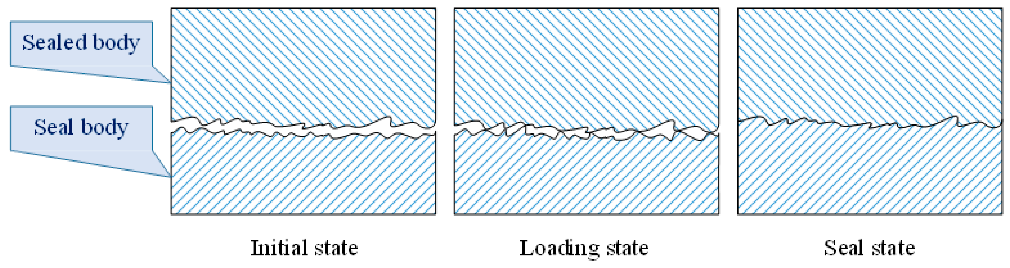
The essence of the metal seal is to isolate the sealed space and prevent mass exchange with the surrounding medium [8,9]. Under ideal conditions, the surface of the sealing body can be fully fitted, forming a tight contact that ensures effective sealing. From a microscopic perspective, the metal-sealing surface is fitted by rough surface contact. The sealing of the metal-sealing element can be regarded as uneven tooth surface engaging under microscopic conditions, as shown in Figure 1 [10]. In the absence of any external force on the contact surface, only the micro-bumps on the surface contact each other, as depicted in the initial state in Figure 1. With the increase in load, the contact surface of the bulge increases with the degree of deformation. Eventually, the bulge begins to deform or embed with each other (Figure 1 loading state). As the load continues to be applied, the micro-clearance of the initial surface roughness is blocked, resulting in most of the mating surface being chimeric and, thus, achieving the metal-sealing effect (Figure 1 seal state) [11,12].
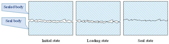
Figure 1.
Metal-sealing process [11,12].
Scholars have performed much research on the sealing characteristics. Li et al. [13] developed a three-dimensional periodic contact finite element model to investigate the impact of varying external pressures and bending moments on the sealing capabilities of subsea wellhead connectors. They examined the effects of contact shape, pre-tightening force, contact width, radial compression, and internal pressure, as well as their influence on the contact stress of the metal-sealing ring. The analysis revealed that an effective seal can be maintained with a compression range of 0.1045–0.2089 mm. The research by Li et al. [14] elucidated the pivotal role of the deepwater wellhead connector’s sealing efficacy in the secure production of deepwater oil and gas wells, since it serves as a crucial subaquatic apparatus. Consequently, the mechanical impact of the actual operational load on the wellhead connector under preload conditions is scrutinized, and the influence of the sealing gasket alongside structural parameters on the operating pressure is delineated. The veracity of both the theoretical computation and the finite element model is validated through a comparison with experimental data contact width and preload. Yun et al. [11] analyzed the contact mechanics and characteristics of the Lens-type sealing mechanism in a subsea Collet Connector, examining both macro and micro aspects. At the macro level, a contact mechanics model for a lens-type metal-sealing steel-sealing gasket was developed, grounded in Hertz theory, to investigate the impact of variables, such as width, contact pressure, and preload on metal seals; at the microscopic level, the contact characteristics of the lens-type sealing structure were examined by varying the peak cutting coefficient. Additionally, the impact of leakage on sealing performance was explored from both radial and circumferential perspectives. Zhang et al. [15] observe that the use of the finite element method (FEM) for assessing the sealing performance and structural integrity of subsea connectors is relatively inefficient. They propose an Analytical Calculation Method (ACM) for the deformation and sealing capability of the steel ring under operational pressure. This method allows for the rapid calculation of sealing performance by obtaining the contact load, contact width, contact pressure, and structural stress under operational conditions, maintaining consistency with FEM results. Hao et al. [16] developed a 3D full-scale finite element model of a subsea hydraulic clamp connector to analyze the impact of the mechanical behavior of sealing components on sealing performance under complex loading conditions. The study indicated that internal pressure loading positively affects the sealing of the subsea connector, whereas the stress distribution in the core sealing component exhibits significant asymmetry under bending moment loads. The superposition of axial tensile loads diminishes the influence of the bending moment on the strength of the core sealing element but further impairs the sealing effectiveness.
To cope with the complex application conditions of the subsea wellhead, this paper presents the design of a novel metal-sealing device for the subsea wellheads used in offshore oil and gas wells. Finite element analysis is conducted to evaluate the sealing characteristics of the sealing device. The analysis simulates the effective stress and surface contact stress of the sealing body under different driving position movements of the sealing device. Verifying the sealing performance of the seal to ensure it meets the sealing requirements will provide theoretical support for structural design and optimization of the metal-sealing device.
2. Mechanism of Metal Sealing and Design of Subsea Wellhead Sealing Device
The sealing assembly plays a critical role in ensuring the integrity of the high-pressure wellhead and casing hanger connection. Its primary functions are as follows [17,18,19]:
- (1)
- Remote operation capability: The seal assembly must be designed to allow for remote installation and retrieval using specialized tools within the high-pressure wellhead. This design requires compatibility with the connecting mechanisms and seal activation mechanisms of these tools.
- (2)
- Locking function: Once the subsea wellhead annular seal device is lowered into the high-pressure wellhead and seated on the shoulder of the casing hanger, it must remain immobile relative to the high-pressure wellhead and casing hanger after sealing is achieved. This requirement necessitates a locking mechanism to secure the device in place.
- (3)
- Sealing function: The annular seal device must make contact with the inner wall of the high-pressure wellhead and the outer wall of the casing hanger to form a seal capable of withstanding rated working conditions. This function is crucial for preventing leaks and maintaining well integrity.
- (4)
- Corrosion resistance: The annular seal device must be resistant to corrosion from seawater, oil, gas, mud, etc., to ensure a safe and reliable seal. Material selection must consider factors, such as pressure and fluid composition, to optimize resistance to corrosion.
The overall requirements for subsea wellhead sealing are crucial to ensure the safe and efficient operation of offshore oil and gas wells. These requirements can be summarized as follows [20,21]:
- (1)
- Reliability: This is the most critical requirement for a subsea wellhead annular seal device. A failure could lead to significant economic losses and environmental contamination. The reliability of the seal must be ensured through a rational device structure, advanced manufacturing techniques, safe transportation processes, and dependable deployment technologies.
- (2)
- Stability: Given that the pressure, temperature, and composition of well media are constantly changing, the annular seal device must adapt to these complex and variable conditions to provide consistent sealing performance. This requires the seal to be designed to withstand fluctuations in these parameters without compromising its integrity.
- (3)
- Durability: The annular seal device must endure throughout the drilling, completion, and production phases, with a long operational lifespan. It must maintain a lasting seal to ensure the safety and security of the oil and gas pathway. In the event of a failure, the original device must be retrieved, and either a repaired or new seal device redeployed, installed, and tested—challenging process, delays normal production, and increases development costs.
Upon excitation, the soft metal of the metal sealing assembly outer layer contacts the hard metal on the casing hanger outer wall and the wellhead inner wall, undergoing elastic–plastic deformation to achieve sealing capabilities [14,16,18].
- (1)
- Elastic Deformation Stage
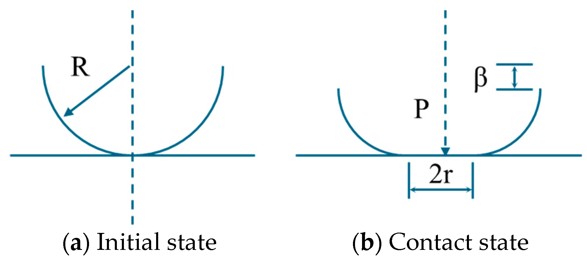
Considering the single micro protrusion as a sphere, the initial state of the sealing pair is depicted in Figure 2a; after applying the sealing force, the contact state of the sealing pair is illustrated in Figure 2b.
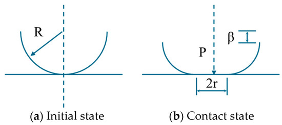
Figure 2.
Status of single micro convex sealing pair.
In the figure, R represents the radius of the micro convex body, r represents the radius of the contact area, β represents the normal deformation, and P represents the sealing driving force.
According to Hertz’s contact theory, it can be inferred that:
In the formula: E represents the equivalent composite elastic modulus, , where E1, E2 and V1, V2 are the elastic modulus and Poisson’s ratio of the two contact materials of the sealing pair.
During this stage, the maximum contact stress is:
- (2)
- Plastic deformation stage
With the increase in fluid pressure, the sealing force must be enhanced when fluid pressure surpasses the contact pressure. This enhancement compels the sealing body to transition from the elastic deformation phase into the plastic deformation phase, thereby attaining an elevated sealing contact stress. The distinction between elastoplastic deformation cannot be discerned through mere observation; rather, the contact state of the interacting objects is determined by the plasticity index φ.
In the formula: H represents material hardness and σ represents the standard deviation of the height distribution of surface roughness micro convex bodies.
When the diameter is less than 0.6, it has an elastic contact, and when the diameter is greater than 1.0, some areas undergo plastic deformation. Most contact is a mixed elastic–plastic deformation state, where the load increases, the plastic contact point increases, and the resulting contact stress increases.
The performance of metal seals can be influenced by a multitude of factors, among which the surface quality of the sealing face, surface roughness, the width of the sealing face, contact stress, and yield strength have a significant impact on the sealing performance.
The surface quality of the sealing face plays a pivotal role in enhancing the fluid resistance, thereby bolstering the sealing performance. Notably, contact surfaces characterized by circular patterns exhibit superior sealing capabilities compared to those with multidirectional or intersecting patterns. This disparity stems from the plastic deformation of multiple annular peaks under the influence of the sealing force, which results in the formation of a labyrinth-like seal [22,23].
The surface roughness of metal-sealing surfaces significantly impacts their performance. If the surface roughness is excessive, the plastic deformation of the sealing surface may be insufficient to fill the leakage channels, allowing the sealing medium to escape through these paths. This issue is particularly pronounced with gases that have small molecular weights and high permeability, as they can more easily leak through. However, once the sealing element undergoes plastic deformation on the contact surface that exceeds twice the yield strength, the surface roughness no longer affects the sealing performance of the system. At this point, permanent deformation occurs at the contact surface, causing the metal to flow and smooth over all surface imperfections. This process effectively seals any potential leakage paths, making the deformation of the sealing surface the sole factor influencing the seal’s performance.
The width of the sealing face is theoretically linked to the length of capillary pores. As the width increases, the path that liquids must traverse through these pores also lengthens, which should correspondingly reduce leakage in an inversely proportional manner. In practice, however, the contact surfaces of the sealing pair may not align perfectly, meaning that the sealing capability does not increase proportionally with the width of the sealing face. Moreover, a wider sealing face necessitates greater external pressure to generate sufficient contact stress for plastic deformation of the metal to occur. Consequently, the width of the sealing face must be chosen judiciously to ensure both effective sealing and practical application of the necessary forces. This balance is crucial for the optimal design and functioning of metal seals.
The contact stress. The contact stress directly impacts the reliability of metal seal assemblies. Under identical external conditions, an insufficient specific sealing pressure fails to provide the necessary contact stress, potentially leading to leakage. Conversely, excessive specific sealing pressure can destabilize and damage the seal components. It is therefore advisable to ensure a minimum specific sealing pressure required for sealing while appropriately increasing the specific sealing pressure when possible. This approach ensures both the effectiveness of the seal and the integrity of the seal components.
The yield strength is an essential factor in metal sealing. By covering the surface of a metal seal with a very thin layer of soft metal, such as silver, aluminum, or copper, these soft metal layers are more prone to plastic deformation during the extrusion process at the sealing interface. This effectively fills and smooths out defects on the sealing surface to achieve the desired sealing effect. This method enhances the adaptability of the seal to surface irregularities and can improve the reliability and lifespan of the seal by compensating for minor defects or damage on the sealing surface. In various engineering applications, selecting materials with appropriate yield strength and carefully designing the sealing components are crucial for optimizing sealing performance.
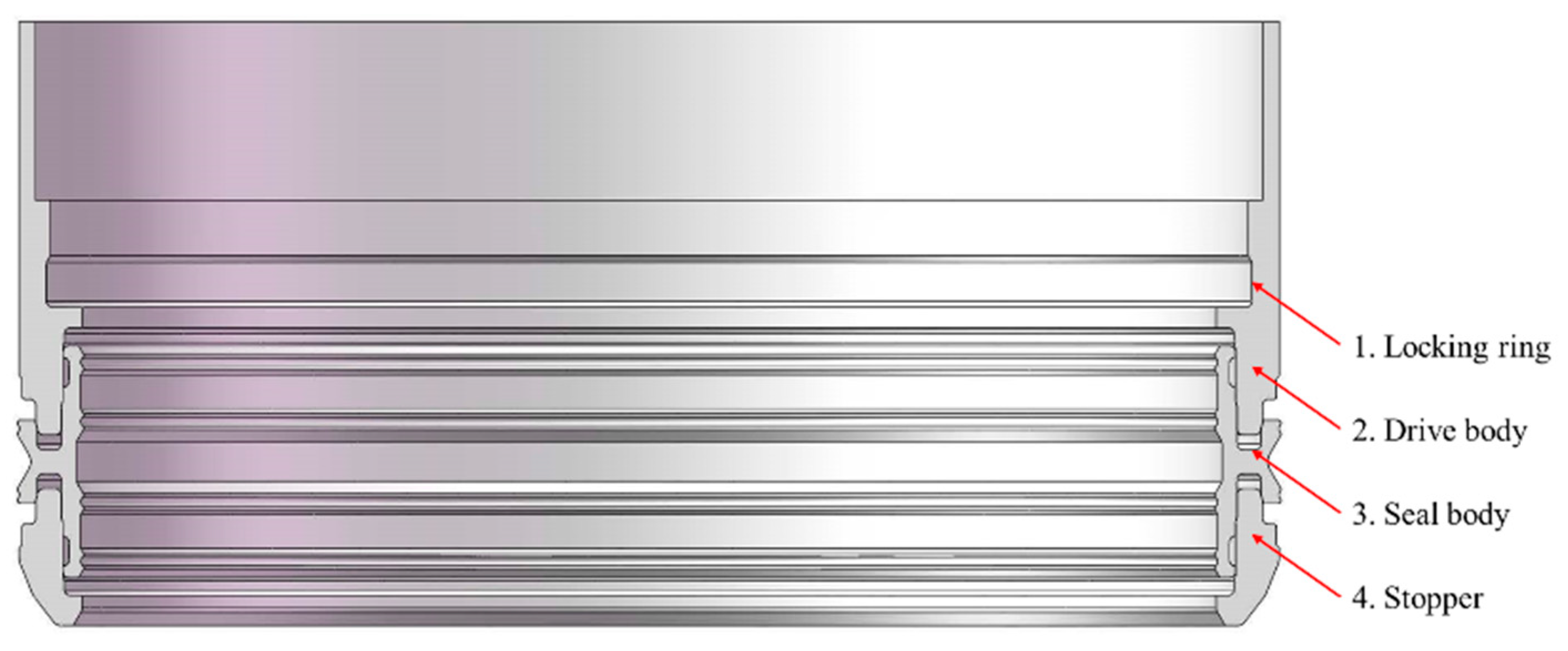
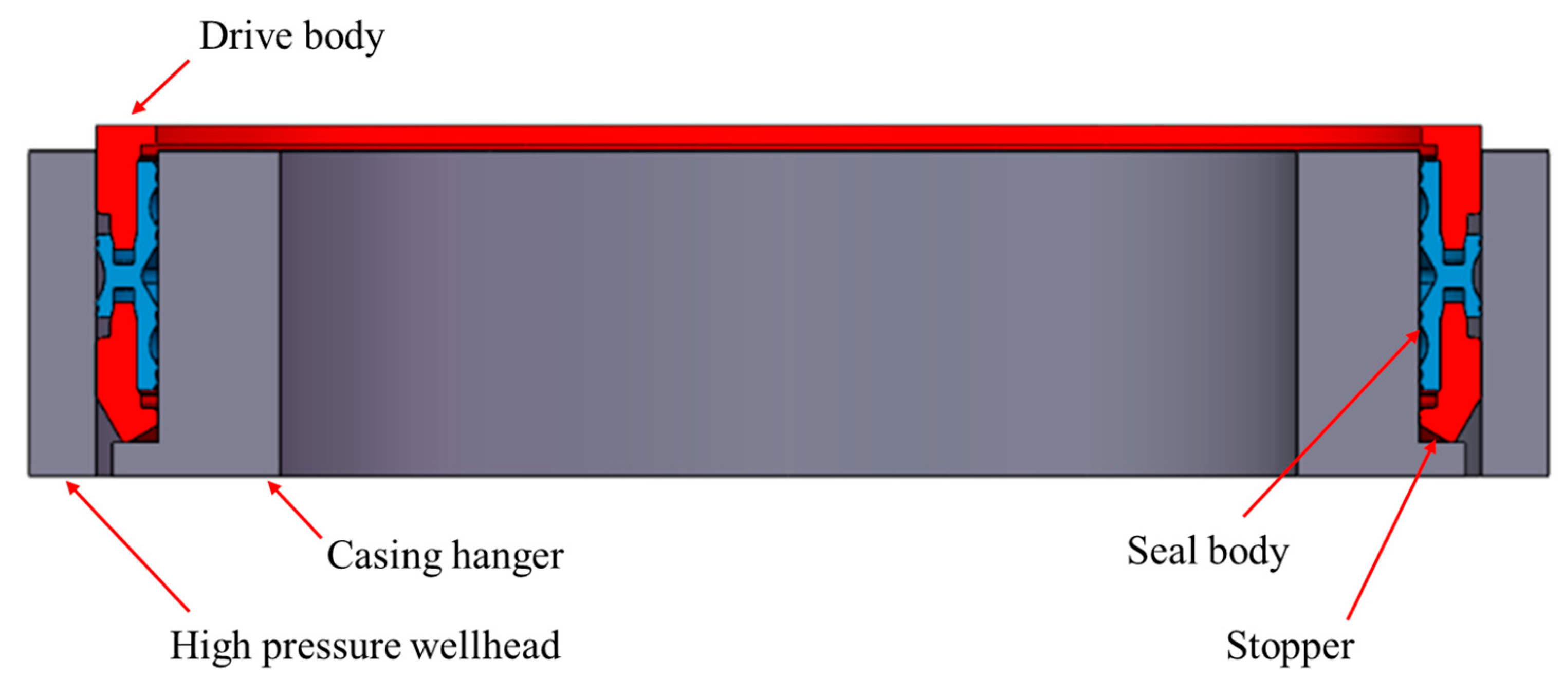
In response to the specified application requirements, a subsea wellhead sealing device has been designed. It is positioned within the annular space between the high-pressure wellhead and the casing hanger. Upon activation of the sealing device’s feeding tool, its sealing component compresses the high-pressure wellhead and casing hanger, ensuring a metal seal. The detailed structure of the sealing device is illustrated in Figure 3.

Figure 3.
Structural diagram of annular metal-sealing device.
The working condition of the sealing device is as follows: The locking pin of the sealing device feeding tool is connected to the concave torus of the inner locking ring (1). Once the sealing device is lowered to the appropriate position of the subsea wellhead, the stopper (4) contacts the shoulder surface of the casing hanger and continues to apply the lower pressure to a certain value, so that the driving body (2) can move down to the appropriate displacement, the metal-sealing body (3) expands to the sealed state, and the sealing device is locked into the casing hanger. Then, the mounting part of the sealing device feeding tool is lifted from the locking ring (1) and lifted to the water surface to complete the installation of the sealing device.
3. Finite Element Analysis of Sealing Device
3.1. Basic Assumption
The working conditions of the subsea wellhead sealing device are complicated. On the premise of ensuring accurate calculation, some simplifications and assumptions are applied for the calculation process of the sealing device:
- Since the sealing device is placed between the high-pressure wellhead and the casing hanger after being lowered, considering that the high-pressure wellhead, the sealing device, and the casing hanger are all rotating bodies. In addition, the force acting on the driving body during the lowering of the sealing device is uniform along the axial direction. At this time, the sealing device exhibits symmetry.
- This analysis and calculation mainly study the sealing performance of the sealing device, ignoring the characteristics unrelated to the sealing performance.
- The bending moment of the sealing device during running is not considered.
- Ignore the influence factors of thermal load.
- Simplified parts have no effect on the result.
- Only the contact between the seal and the high-pressure wellhead and casing hanger is considered in the running process.
3.2. Physical Model
Given that the primary structure of each section is axisymmetric, an axisymmetric computational model was selected. Only the components pertinent to sealing are retained to enhance computational efficiency. Additionally, the intricate details within the sealed regions are preserved to ensure the accuracy of the analysis results. The assembly model depicting the initial sealed state is illustrated in Figure 4.
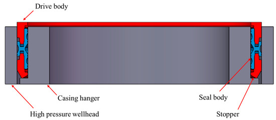
Figure 4.
Key parts model of sealing device.
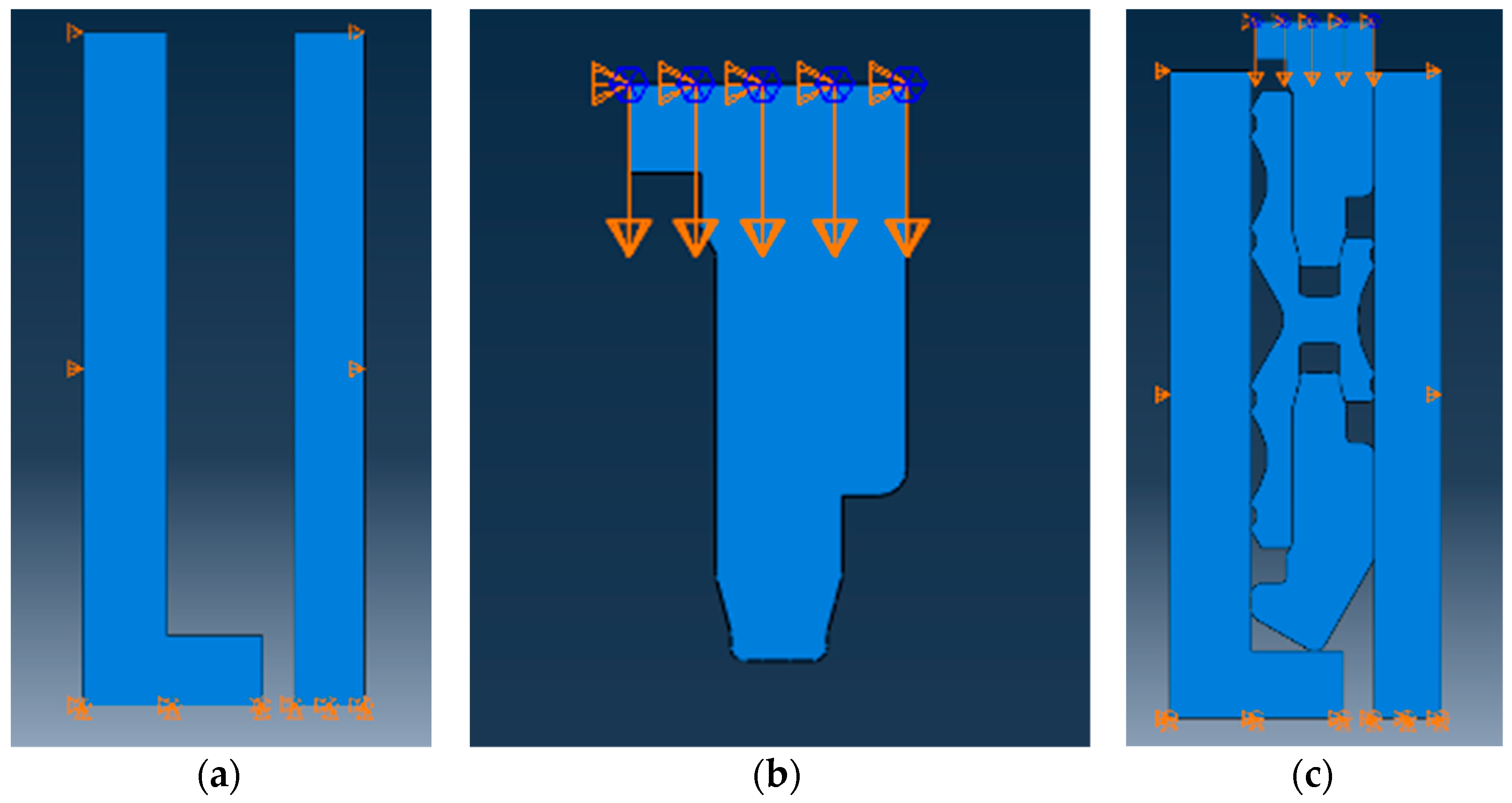
In the above model, the casing hanger and the high-pressure well mouth are set as elastomers. The constraints imposed by each part of the model are shown in Figure 5.
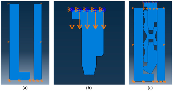
Figure 5.
Constraint setting in the axisymmetric model. (a) The verbal constraint between the casing hanger and the high-pressure wellhead; (b) the constraint of the feeding body; and (c) global constraint.
According to mesh density and mesh elements, four-node bilinear axisymmetric quadrilateral elements were selected for grid division. Meanwhile, to ensure contact convergence, the independence of the grid is verified, as depicted in Figure 6.
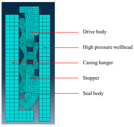
Figure 6.
Quadrilateral grid element.
3.3. Material Selection
The sealing body is the main component to realize the metal seal during the installation of the annular metal seal device, and it is the focus of the finite element analysis. The material properties of the sealing body are shown in Table 1.

Table 1.
Material properties of sealing body.
The elastic–plastic deformation behavior of metal materials can be summarized as follows: at small strain, the material exhibits linear elastic property, and the elastic modulus E remains constant. When the stress exceeds the yield stress, the stiffness will decrease significantly, and the strain of the material will include plastic strain and elastic strain. Upon unloading, the elastic strain disappears, whereas the plastic strain is irreversible. Reloading the material will result in a further increase in the yield stress; this phenomenon referred as work hardening.
3.4. Strength Criterion
During the inspection of the sealing device, it is important to ensure that the pressure applied to the contact surface exceeds the yield limit of the sealing body, which is made of a soft metal. This will cause plastic deformation and ensure that the sealing device is properly activated and able to perform its sealing function. According to the material used in the sealing device, the minimum Von Mises equivalent stress should exceed the yield limit of 414 Mpa.
The strength failure criterion for sealing devices is based on the Von Mises equivalent stress theory (the fourth strength theory). During the finite element analysis, the Von Mises equivalent stress theory was adopted in the analysis trial calculation.
In the formula, σ is Von Mises equivalent stress, σ1, σ2, and σ3 represent principal stresses in three directions, respectively.
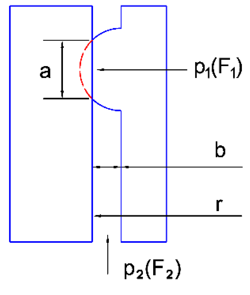
The driving sleeve drives the sealing body to open so that the flange of the sealing body is in contact with the high-pressure wellhead and casing hanger. After sealing, the flange deformation of the sealing body is shown in Figure 7. In the figure, p1 is the pressure acting on the flange of the sealing body, p2 is the pressure in the well, a is the width of the contact surface after the deformation of the flange of the sealing body, b is the cross-section width of the annular space in the well, r is the theoretical radius of the sealing surface, F1 is the normal force acting on the flange, and F2 is the normal force acting on the annular surface of the well pressure. The material hardness of the sealing ring is smaller than that of the high-pressure wellhead and casing hanger. Therefore, the deformation of the sealing ring is the main factor, and the deformation of the high-pressure wellhead and casing hanger is ignored here [24].
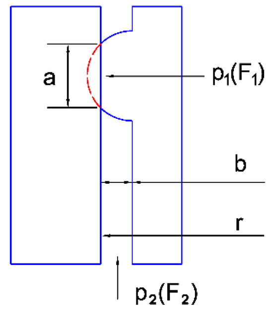
Figure 7.
Deformation force diagram of the sealing ring flange.
The condition at which the sealing device can achieve the sealing effect is F1 ≥ F2, then:
where S1 is the area of the sealing surface, S2 is the horizontal projection area of the toroidal surface, and S2 < 2πrb. It can be obtained from the above equation:
At this time, the sealing ring flange has plastic deformation with a large amount of deformation, which is, a > b, so it can be obtained that S1 > S2. Considering that the working pressure of the wellbore is p2 = 68.9 MPa (10,000 psi), the sealing effect of the sealing device can be guaranteed as long as the contact surface stress, p1, of the sealing surface is not less than the well pressure, p2, that is, p1 > p2. At the same time, the minimum sealing contact pressure of the sealing surface should be no less than the sealing medium pressure of 1.2~1.4, which is:
Among them, qMF is the minimum sealing contact pressure in MPa, and Pd is the pressure of the sealing medium in MPa. In this example, Pd = 68.9 MPa and qMF ≥ 82.68~96.46 MPa.
3.5. Loads and Boundary Conditions
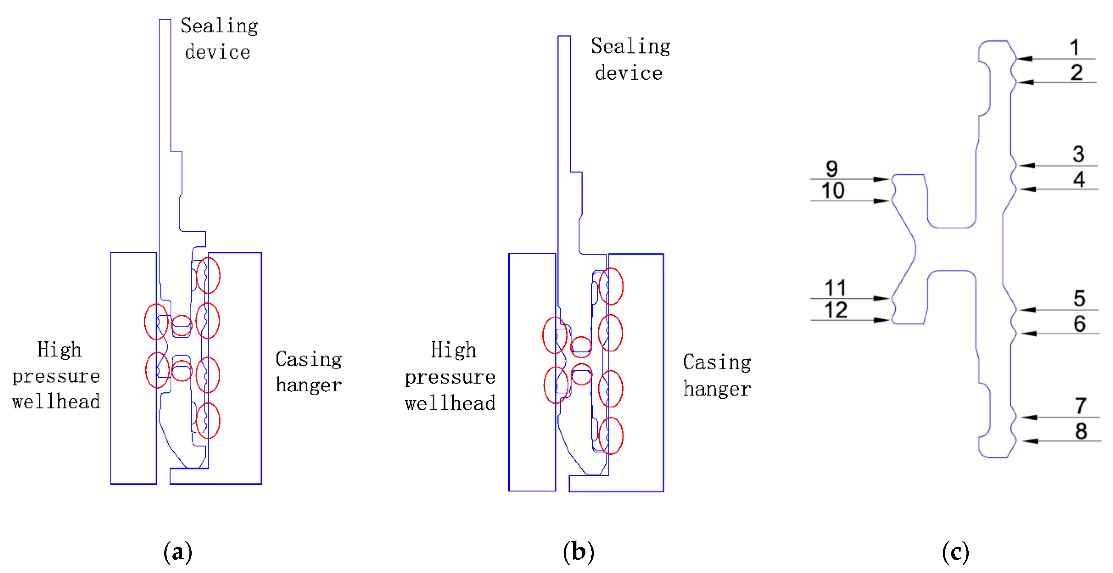
During the lowering process, the sealing device feeding tool and the sealing device are connected through the tooth block under only the action of gravity; the sealing body is not affected. During the installation process, the driving body is inserted into the sealing body to generate excitation to achieve sealing. The mechanical model is displaced in Figure 8.
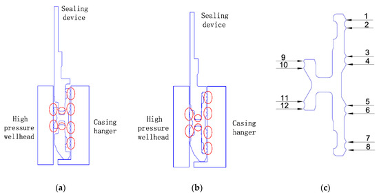
Figure 8.
The sealing physical model (a) before excitation and (b) after excitation. (c) The sealing flange number.
Upon seating the sealing body, the flange of the metal seal body begins to undergo obvious deformation, and the upper flange of the outer sealing surface (on the oral side of the high-pressure well) and the inner sealing surface (on the side of the casing hanger) expand outwards under the excitation of the driver body. Once it is set, the sealing ring is fully open, the outer flange is in contact with the high-pressure wellhead, and the inner flange is in contact with the casing hanger. The extrusion of the driving body makes the maximum stress of the seal body occur at the flange, and the plastic deformation occurs at the flange to form a continuous sealing surface with a certain width. The maximum Von Mises stress of the sealing body is greater than 414 MPa, ensuring that the strength of the sealing body meets the design requirements. Also, since the contact stress of the sealing surface is the criterion to determine whether the sealing device has the sealing capability, stress analysis should be performed at the key contact locations, including the contact stress between the inner and outer flanges.
4. Model Calculation
The sealing device is running through the feeding tool. During the installation process of the sealing device, the driving body undergoes displacement and transitions from the initial assembly state to the contact state. Subsequently, plastic deformation takes places at the flange of the sealing body to realize the metal seal. The above process determines the stress status of the sealing body and confirms whether the sealing body has entered the plastic deformation stage according to the elastic analysis results of the metal-sealing device.
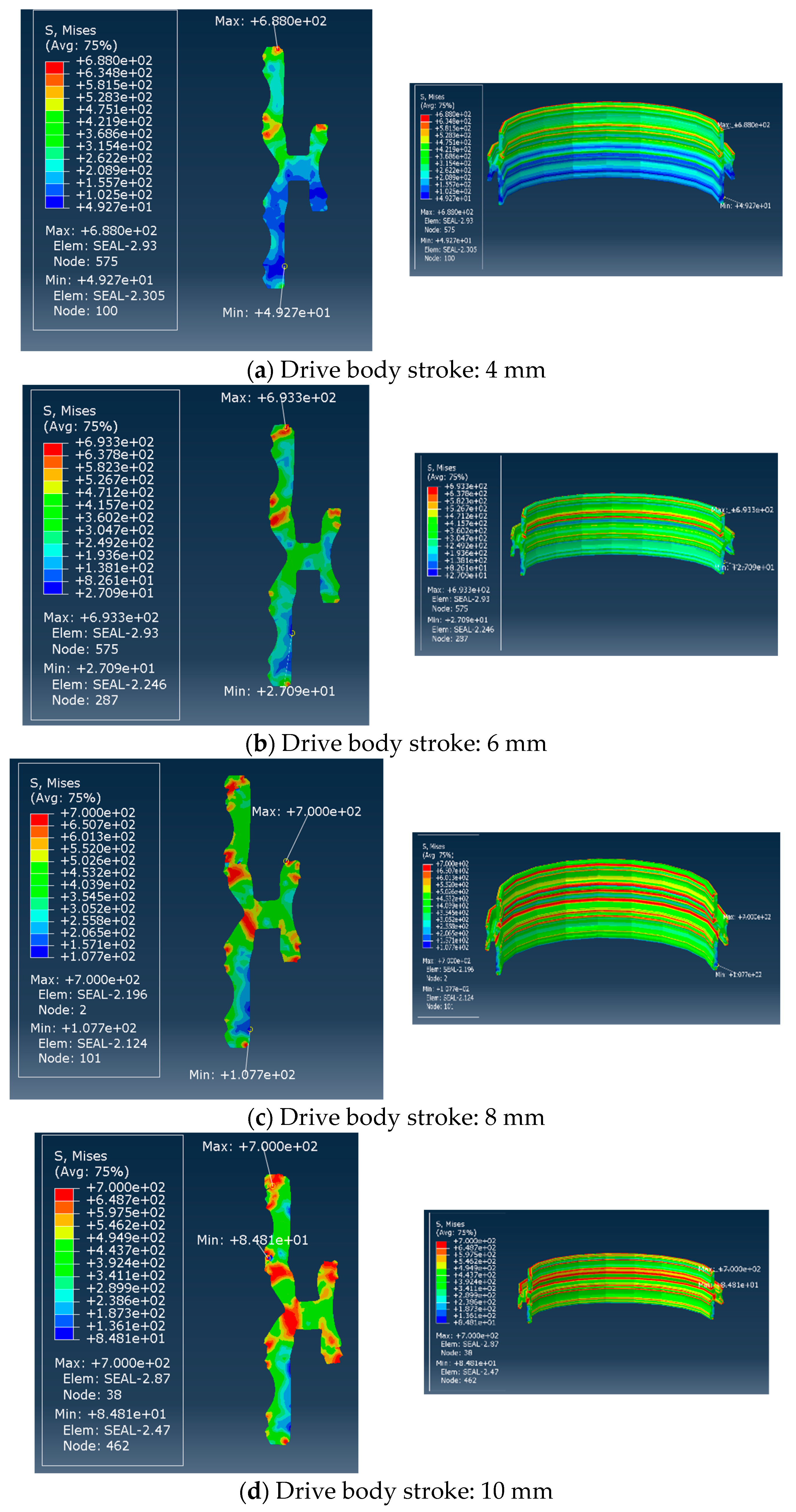
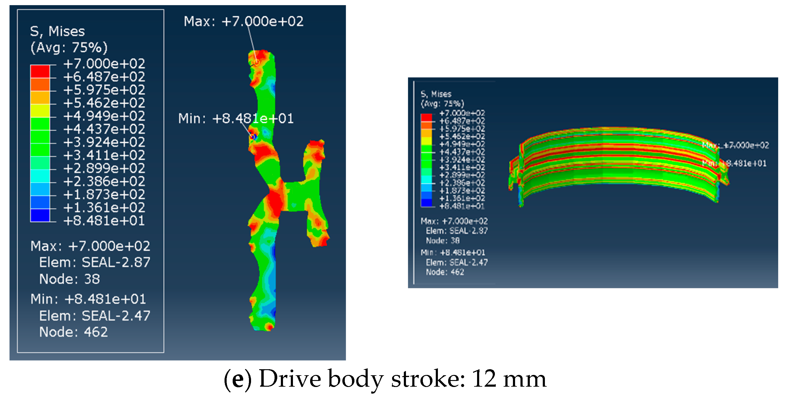
During the above installation process, the sealing body is fitted with the casing hanger and the high-pressure wellhead. The driving body is pressed into the annular space of the sealing body, and the overall displacement of the excitation is 12 mm. To analyze the stress and deformation state of the sealing body when the driving body is pressed with different strokes, the drive body will move down from the assembly state and press into the seal body with strokes of 4 mm, 6 mm, 8 mm, 10 mm, and 12 mm, respectively. The force and deformation of the sealing body are analyzed, and the calculation results are presented in Figure 9.
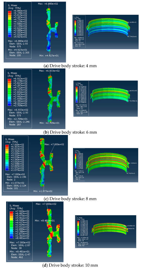

Figure 9.
Stress nephogram of sealing ring with different strokes.
At a drive distance of 4mm, the sealing flanges 1, 2, 3, 4, and 5, which are matched with the casing hanger, have been mutually extruded with the casing hanger and have reached the plastic deformation stage, resulting in a maximum stress is 652 MPa. The sealing flanges 9 and 10, which are matched with the high-pressure wellhead, are verbally extruded with the high-pressure well and reached plastic deformation also; the maximum stress is 453 MPa. Once the drive distance reached 6–12 mm, the minimum Von Mises stress of 12 flanges exceeded the yield stress, causing the sealing body to enter the plastic stage.
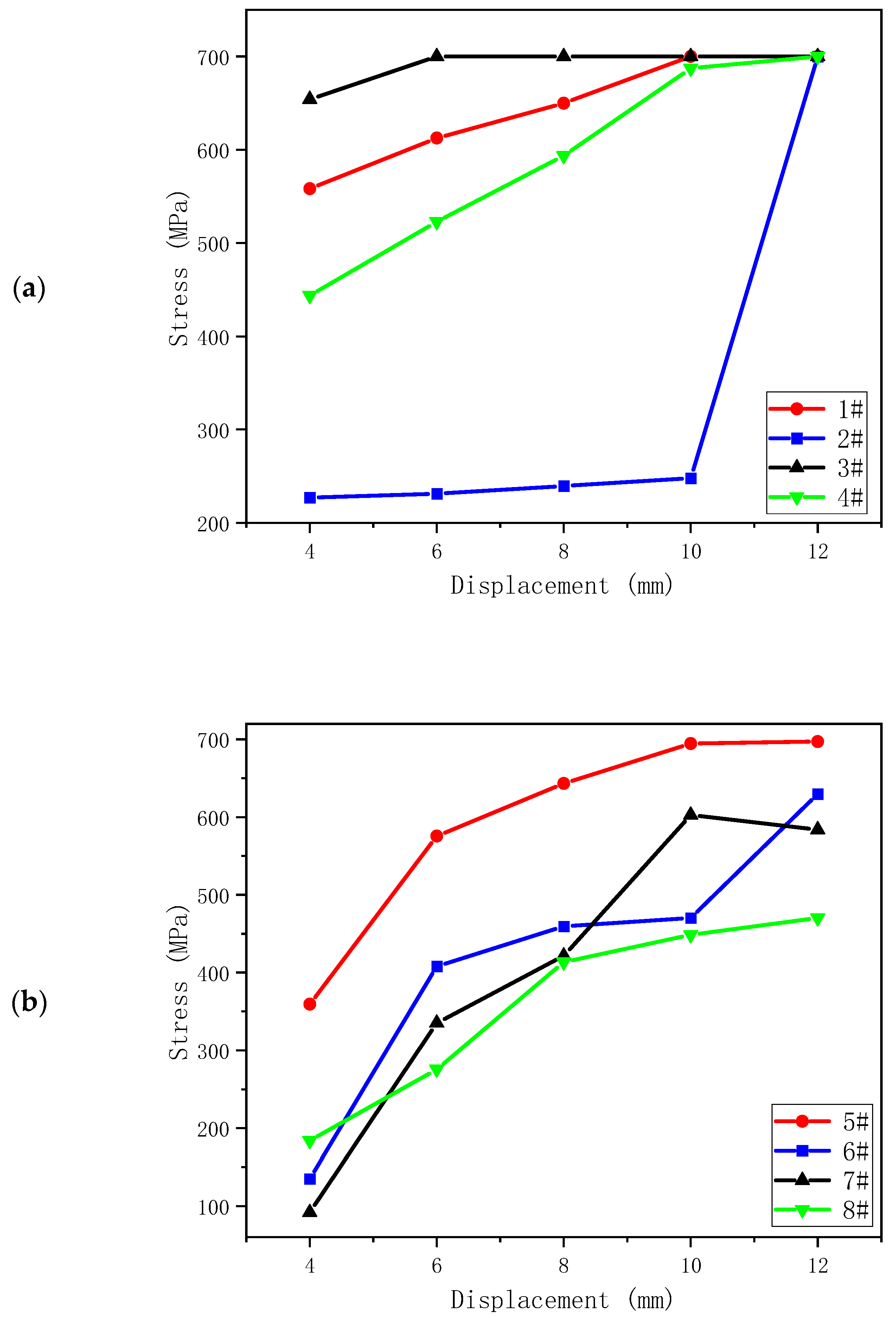
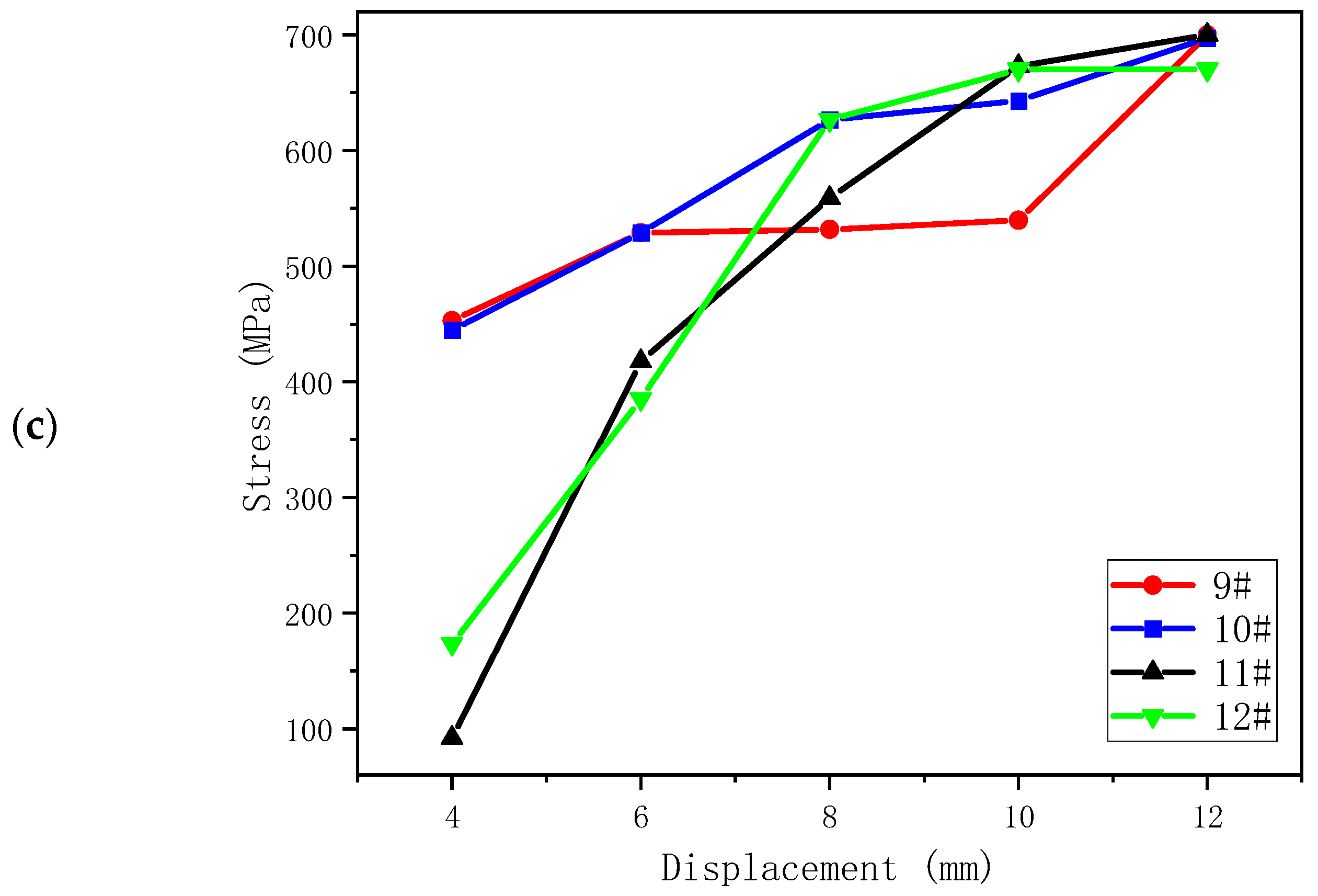
The calculation results of the sealing ring under 5 strokes are summarized in Figure 10. For flanges 1–4, after the sealing ring is lowered into the annular space between the casing hanger and the wellhead for 4 mm, flange 1 on the sealing body has mutual extrusion with the casing hanger. The stress increased from 0 to 557 MPa. As the distance increased, the maximum equivalent stress reached 700 MPa, which was nearly 3.5 times the yield limit of the material. This feature can provide better sealing performance. Among the range of flanges 5–8, the stress of number 6 first changes slowly due to the small initial contact area. However, with the increase in displacement, the extrusion stress rapidly rises to 409 MPa. Subsequently, the maximum equivalent stress rapidly reaches 630.542 MPa, indicating that sealing performance has been achieved. Under the extrusion between the casing hanger and high-pressure wellhead, the stress at flange 11 in 9–12 rapidly increases to 419 MPa. With the increase in distance, the equivalent stress rapidly increases to 700 MPa, realizing the sealing performance.
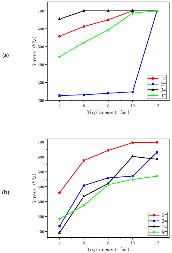
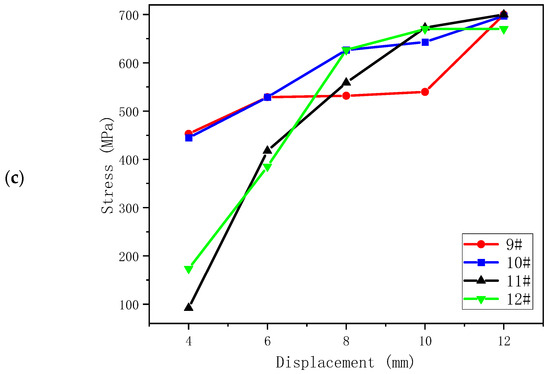
Figure 10.
Stress variation trend of sealing flanges 1–12: (a) flanges 1–4; (b) flanges 5–8; and (c) flanges 9–12.
5. Contact Stress Analysis of Sealing Surface
The metal-sealing device is located between the subsea high-pressure wellhead and the casing hanger. When the driving body applies the downward load, the sealing body of the sealing device will undergo plastic deformation and will start to expand outwards, where it comes into contact with the high-pressure wellhead and the casing hanger. In this process, the tiny gap between the sealing device, casing hanger, and the high-pressure wellhead will be filled by the sealing material. Thus, blocking the tiny channel will form a metal sealing [25]. To achieve a complete absence of leakage or a very low leakage rate, a continuous tight fit of the sealing surface is required. The contact surface of different metal sealing exhibits various rough textures. When the sealing body is in the initial stage, only the highest part of the corresponding micro-convex body on the surface contacts with each other, so there are many micro-discharge channels. With the increase in load, the contact quantity and deformation degree of micro-flange gradually increase. In this stage, plastic deformation appears, and rough surfaces inlay into each other, blocking the micro-discharge channels and reducing the leakage rate to form a seal. In metal-to-metal sealing, to achieve a low leakage rate, the extrusion stress of the material must exceed the elastic limit of the material, resulting in plastic deformation, to achieve sealing [26,27].
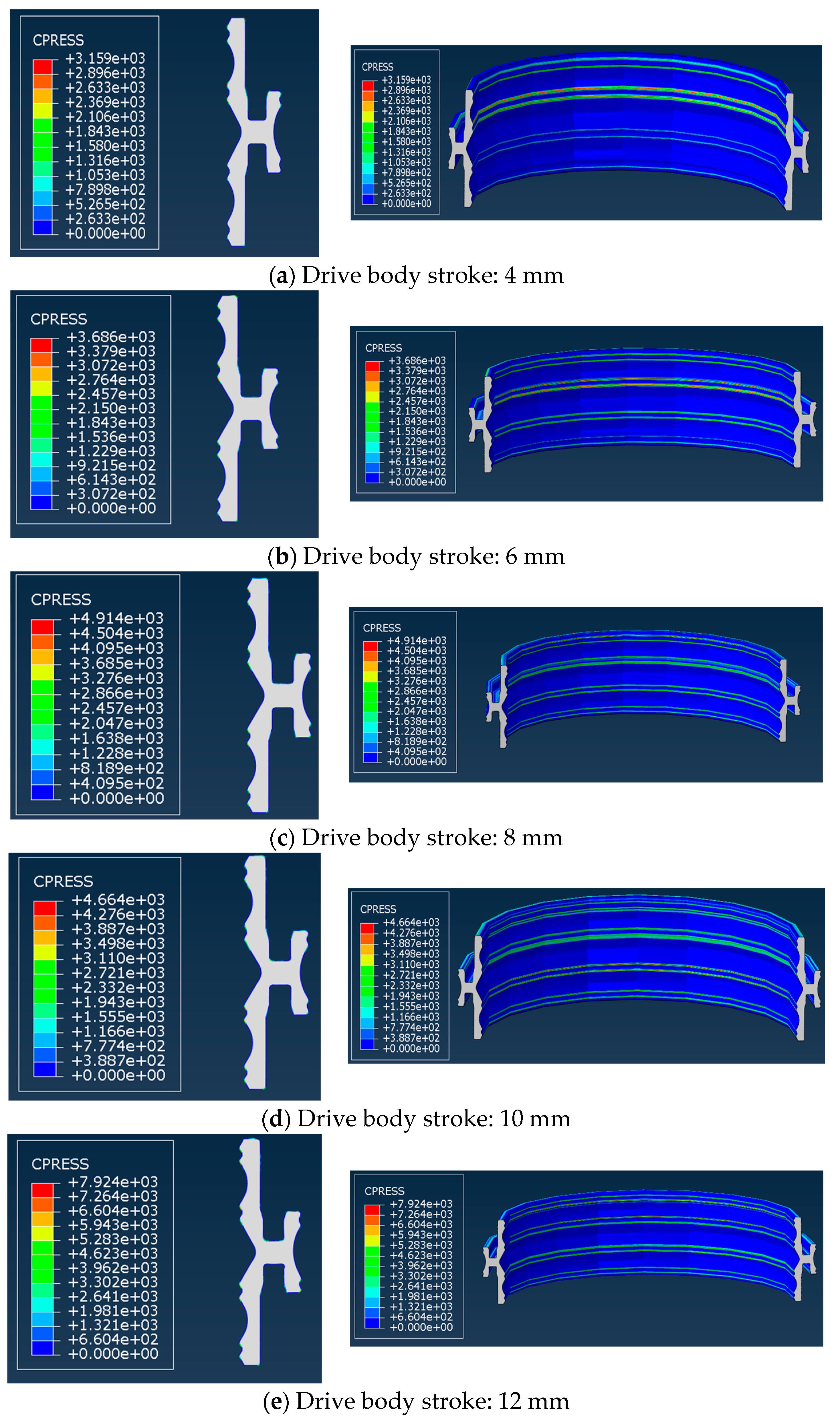
According to the sealing device model, the contact stress of the sealing body is analyzed. The nephogram of the contact stress is shown in Figure 11. In the figures, some of the contact stress levels are relatively higher than others due to the occurrence of self-contact behavior throughout the running process. This results in local stress concentration on the surface of the sealing body. The finite element simulation result is well consistent with the engineering practice.
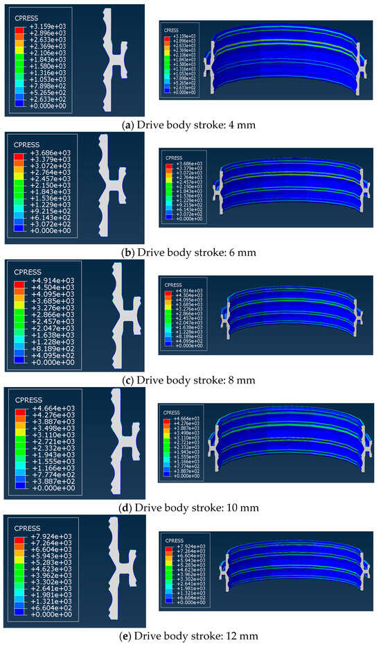
Figure 11.
Contact stress of sealing ring with different strokes.
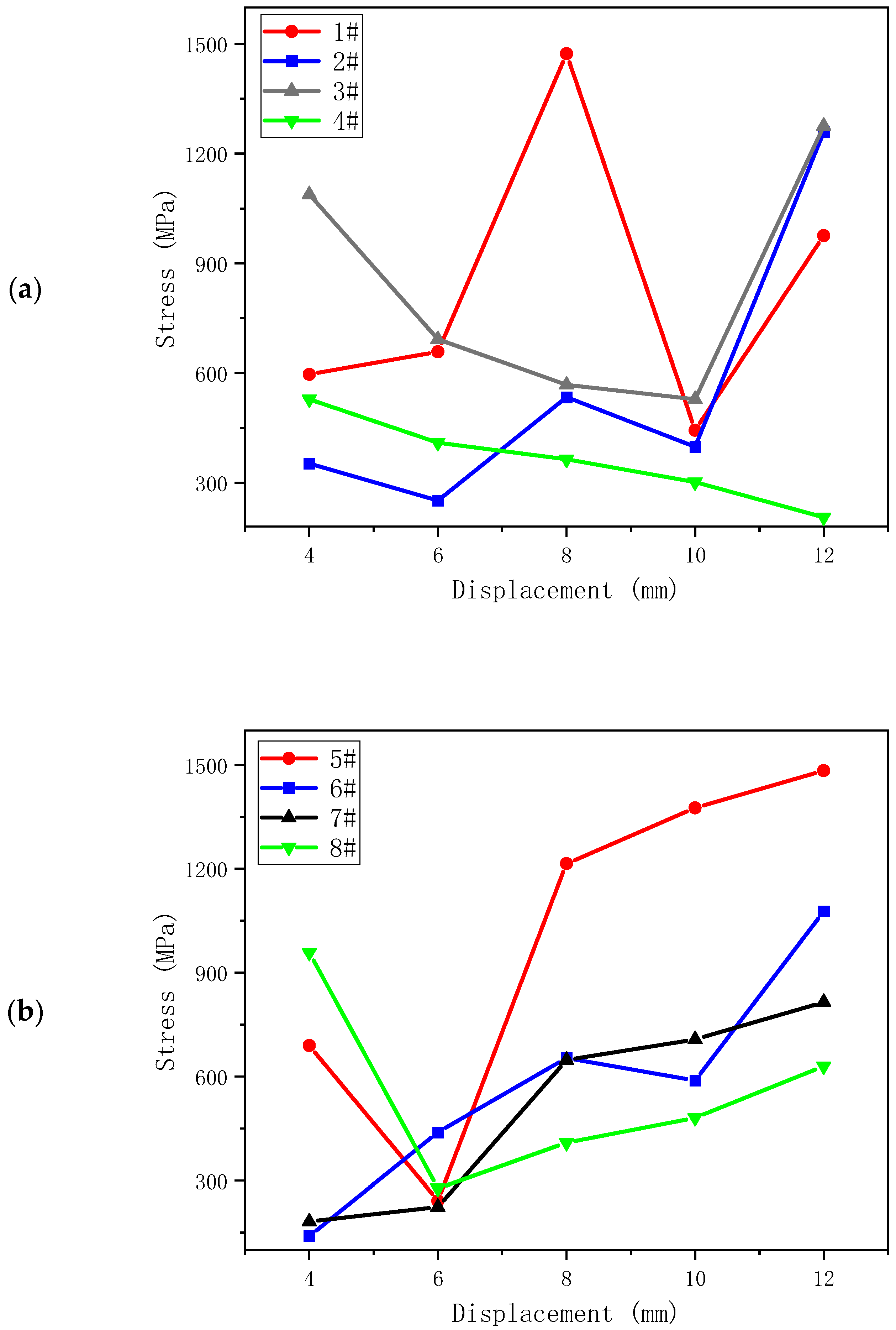
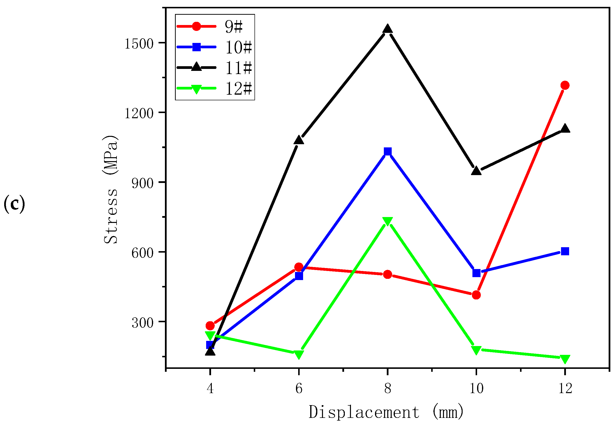
According to the contact stress at the 12 flanges of the sealing body, the drive body stroke-contact stress diagram is drawn, as depicted in Figure 12. It is evident that the overall contact stress presents an upward trend. Upon analyzing the sealing point at each position, it is clear that the maximum contact stress exceeds twice the yield stress of the material, hence meeting the requirements of plastic deformation. The reduction in contact stress in some positions is mainly attributed to the increase in the contact area.
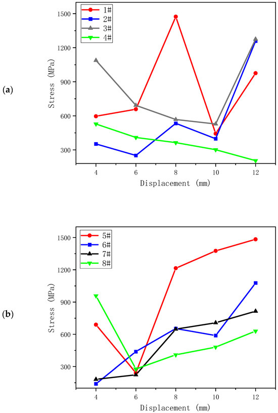
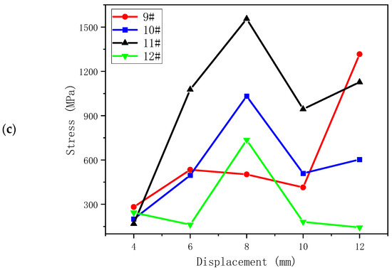
Figure 12.
Contact stress variation trends of sealing flanges 1–12: (a) flanges 1–4; (b) flanges 5–8; and (c) flanges 9–12.
6. Conclusions
- A new type of subsea wellhead metal-sealing device is designed, and the physical model of finite element analysis is established to solve and verify the effective stress of the device. Once the sealing device is set, the sealing ring opens and the outer flange contacts with the high-pressure wellhead while the inner flange contacts with the casing hanger. When the driving body sits in the design position, the sealing body flange experiences a quick increase in effective stress to reach 600–700 MPa, causing the sealing body to yield. This is consistent with the metal-sealing principle and ensures effective sealing.
- The analysis of contact stress at the sealing convex contact point reveals that the contact stress exceeds three times the yield strength of the sealing metal. This realizes the plastic deformation of the sealing body and ensures the sealing effect of the sealing body.
- Due to the plastic deformation of some sealing contacts, the contact stress decreases. Subsequently, the structure of the sealing body can be optimized to ensure the uniform contact stress of the contact points and further ensure the sealing effect.
Author Contributions
Study planning, ideas, J.L. and B.K.; methodology, B.N.; informational and data analysis, D.Q., F.O. and L.G.; literature evaluation, B.K. and P.X.; writing—review and editing, J.L. and P.X. All authors have read and agreed to the published version of the manuscript.
Funding
The authors gratefully acknowledge the financial support from Science and Technology Project in Guangzhou (Grant number: No. 2023A04J0306). This research is also supported by the China Geological Survey (Grant number: No. DD20230066) and the National Engineering Research Center of Gas Hydrate Exploration and Development (No. NERCY202405).
Data Availability Statement
Data are contained within the article.
Acknowledgments
The authors would like to thank the reviewers for their many constructive suggestions and comments that helped improve the quality of the paper.
Conflicts of Interest
Author Beibei Kou was employed by the company Guangdong Nanyou Holding Group Co., Ltd. The remaining authors declare that the research was conducted in the absence of any commercial or financial relationships that could be construed as a potential conflict of interest.
References
- Wang, Y.B.; Zeng, J.; Gao, D.L. Effect of annular pressure on the fatigue damage of deepwater subsea wellheads. Nat. Gas Ind. 2020, 40, 116–123. [Google Scholar]
- Zhang, M.; Yang, J.; Liu, H.; Li, L.; Fu, C.; Yang, Y.; Xu, D.; Ma, K. A mechanism of expandable conductor used to improve the bearing capacity of subsea wellhead in deep-water drilling. Acta Pet. Sin. 2021, 42, 791–800. [Google Scholar]
- Li, Z.G.; Jia, P.; Wang, H.H.; Zhang, N.; Wang, L. Development trend and active research areas of subsea production system. J. Harbin Eng. Univ. 2019, 40, 944–952. [Google Scholar]
- Li, Q.; Sun, Q.; Cheng, B.; Liu, G.; Yao, H.; Wang, J.; Liu, Y.; Qin, R.; Cui, Y.; Tian, J.; et al. Key technologies for engineering design of deepwater subsea production system in LS17-2 gas field. China Offshore Oil Gas 2021, 33, 180–188. [Google Scholar]
- Tang, Y.; Zhang, Z.G.; Yi, X.D.; Liu, P.; An, J. Connectors for an Underwater Production System and Key Techniques. J. Southwest Pet. Univ. 2019, 41, 160–168. [Google Scholar]
- Sun, B.B.; Wang, L.T.; Xu, X.P.; Wang, H. Research on Influencing Factors of Contact Stress of Seal Assembly Inner Flange. China Pet. Mach. 2020, 48, 85–89. [Google Scholar]
- Hou, C.; Xiao, W.S.; Liu, J.; Liu, Z. Review on Subsea Well System Sealing Technology Research. Lubr. Eng. 2015, 40, 110–114. [Google Scholar]
- Yan, H.; Zhao, Y.; Liu, J.; Jiang, H. Analyses toward factors influencing sealing clearance of a metal rubber seal and derivation of a calculation formula. Chin. J. Aeronaut. 2016, 29, 292–296. [Google Scholar] [CrossRef]
- Qin, H.Z. Serialization Design and Research of Seal Assembly of Subsea Wellhead System; China University of Petroleum: Beijing, China, 2014. [Google Scholar]
- Hou, C. Structure Design and Reliability Study of Subsea Wellhead Seal Assembly; China University of Petroleum: Beijing, China, 2015. [Google Scholar]
- Yun, F.; Wang, G.; Yan, Z.; Jia, P.; Xu, X.; Wang, L.; Sun, H.; Liu, W. Analysis of Sealing and Leakage Performance of the Subsea Collet Connector with Lens-Type Sealing Structure. J. Mar. Sci. Eng. 2020, 8, 444. [Google Scholar] [CrossRef]
- Qiang, Y.L.; Wu, J.H.; Li, S.M.; Bian, J.; Liu, J.; Cao, Y.G.; Yan, X.X.; Li, X.L. Current situation of wellhead sealing technology abroad—Metal seal. China Pet. Mach. 2014, 42, 32–36. [Google Scholar]
- Li, Y.; Su, H.; Wang, Y.; Mou, L.; Wang, Q.; Ren, Y. Research on bearing capacity and sealing contact characteristics of the subsea wellhead connector. Proc. Inst. Mech. Eng. Part M J. Eng. Marit. Environ. 2023, 237, 153–165. [Google Scholar] [CrossRef]
- Li, Y.; Zhao, H.; Wang, D.; Xu, Y. Metal sealing mechanism and experimental study of the subsea wellhead connector. J. Braz. Soc. Mech. Sci. Eng. 2020, 42, 1–17. [Google Scholar] [CrossRef]
- Zhang, K.; Liu, J.; Duan, M. Analytical calculation method for predicting compression deformations and sealing performance of subsea connector under operating condition. Int. J. Press. Vessel. Pip. 2023, 202, 104902. [Google Scholar] [CrossRef]
- Hao, X.; Yun, F.; Jiao, K.; Chen, X.; Jia, P.; Wang, X.; Wang, L. Mechanical Behavior and Sealing Performance Study of Subsea Connector Core-Sealing Components under the Combined Action of Internal Pressure, Bending Moment, and Axial Load. J. Mar. Sci. Eng. 2023, 11, 1691. [Google Scholar] [CrossRef]
- Wei, Z.; Wang, L.; Guan, Y.; Yao, S.; Li, S. Static metal sealing mechanism of a subsea pipeline mechanical connector. Adv. Mech. Eng. 2016, 8, 1687814016654821. [Google Scholar] [CrossRef]
- Liao, C.; Fang, H.; Wang, H.; Man, M. Study on characteristics and mathematical models of stress relaxation for metal O-rings. Proc. Inst. Mech. Eng. Part J J. Eng. Tribol. 2017, 231, 826–837. [Google Scholar] [CrossRef]
- Yun, F.; Liu, D.; Xu, X.; Jiao, K.; Hao, X.; Wang, L.; Yan, Z.; Jia, P.; Wang, X.; Liang, B. Thermal–Structural Coupling Analysis of Subsea Connector Sealing Contact. Appl. Sci. 2022, 12, 3194. [Google Scholar] [CrossRef]
- Zhao, H.; Chen, R.; Luo, X.; Duan, M.; Lu, Y.; Fu, G.; Tian, H.; Ye, D. Metal sealing performance of subsea X-tree wellhead connector sealer. Chin. J. Mech. Eng. 2015, 28, 649–656. [Google Scholar] [CrossRef]
- Wang, Y.; Chen, Z.; Yan, Q.; Hu, Y.; Wang, C.; Luo, W.; Cai, B. A dynamic failure analysis methodology for fault diagnosis of fatigue cracks of subsea wellhead connectors with material aging. Process Saf. Environ. Prot. 2022, 159, 36–52. [Google Scholar] [CrossRef]
- Ji, N.; Wang, P.; Xie, J.; Zhao, M.; Feng, C.; Xie, J. Small-scale Experimental Research on the Key Parameters Affecting Metal-to-metal Sealability. J. Phys. Conf. Ser. 2023, 2610, 012034. [Google Scholar] [CrossRef]
- Wang, Y.; Luo, W.; Liu, S.; Feng, H.; Li, J.; Wang, J. A model for reliability assessment of sealing performance of the C-shaped metal sealing ring at the outlet of the subsea tubing hanger. Ocean. Eng. 2022, 243, 110311. [Google Scholar] [CrossRef]
- Zhang, K. Design Theory of Subsea Collet Locking Mechanism under Sealing and Strength Constraints; China University of Petroleum: Beijing, China, 2017. [Google Scholar]
- He, D.S.; Ren, H.; Zhang, L.F.; Li, Z.; Zhu, H. Study on Sealing Performance of Downhole V-shaped Metal Sealing Ring. Lubr. Eng. 2020, 45, 81–86+128. [Google Scholar]
- Yang, Y.W.; Zhu, H.W.; He, D.S.; Zheng, Y.; Ye, Z.; Xu, L.; He, Y.; Li, C. Theoretical and Simulation Study on Contact Mechanical Behaviors of Metal Seal of Inflow Control Valve. Lubr. Eng. 2020, 45, 15–21. [Google Scholar]
- He, D.S.; Dai, H.; Xie, X.L.; Li, C.; Wang, B. Research on Performance of U-shaped Metal Sealing Ring Based on Abaqus. Lubr. Eng. 2021, 46, 26–30. [Google Scholar]

Disclaimer/Publisher’s Note: The statements, opinions and data contained in all publications are solely those of the individual author(s) and contributor(s) and not of MDPI and/or the editor(s). MDPI and/or the editor(s) disclaim responsibility for any injury to people or property resulting from any ideas, methods, instructions or products referred to in the content. |
© 2024 by the authors. Licensee MDPI, Basel, Switzerland. This article is an open access article distributed under the terms and conditions of the Creative Commons Attribution (CC BY) license (https://creativecommons.org/licenses/by/4.0/).