Abstract
Stator faults are one of the common issues in pumped storage generators, significantly impacting their performance and safety. To ensure the safe and stable operation of pumped storage generators, a stator fault diagnosis method based on an improved short-time Fourier transform (STFT)-support vector data description (SVDD) hybrid algorithm is proposed. This method establishes a fault model for inter-turn short circuits in the stator windings of pumped storage generators and analyzes the electrical and magnetic states associated with such faults. Based on the three-phase current signals observed during an inter-turn short circuit fault in the stator windings, the three-phase currents are first converted into two-phase currents using the principle of equal magnetic potential. Then, the STFT is applied to transform the time-domain signals of the stator’s two-phase currents into frequency-domain signals, and the resulting fault current spectrum is input into the improved SVDD network for processing. This ultimately outputs the diagnosis result for inter-turn short circuit faults in the stator windings of the pumped storage generator. Experimental results demonstrate that this method can effectively distinguish between normal and faulty states in pumped storage generators, enabling the diagnosis of inter-turn short circuit faults in stator windings with low cross-entropy loss. Through analysis, under small data sample conditions, the accuracy of the proposed method in this paper can be improved by up to 7.2%. In the presence of strong noise interference, the fault diagnosis accuracy of the proposed method remains above 90%, and compared to conventional methods, the fault diagnosis accuracy can be improved by up to 6.9%. This demonstrates that the proposed method possesses excellent noise robustness and small sample learning ability, making it effective in complex, dynamic, and noisy environments.
1. Introduction
A pumped hydroelectric storage facility represents an advanced energy storage solution, leveraging the motor functionality to elevate water from a lower to a higher reservoir. Upon demand, this stored water is released to propel turbines, thereby generating electricity [1]. Amidst the global pursuit of “dual carbon” objectives, the integration of renewable energy sources has markedly escalated [2]. Nevertheless, the intermittent nature of these sources poses challenges to their widespread adoption and efficient utilization. Pumped storage power stations emerge as a pivotal tool, adept at balancing peak loads and stabilizing frequencies, significantly bolstering the consumption potential of renewable energies. Among the myriad energy storage technologies, pumped storage stands out for its cost-effectiveness, technological maturity, eco-friendliness, and extended operational lifespan [3,4]. As a result, the momentum for constructing such facilities is steadily gathering pace.
With the rapid construction of pumped storage power stations in China, there are increasingly higher requirements for their safe and stable operation, as well as for the fault detection of the core equipment, the generator-motor [5]. The causes of inter-turn short circuits in the rotor windings of generator-motors can be diverse, primarily including insulation aging or damage, winding overheating, and vibration or mechanical damage [6,7]. Aging or damage to insulation materials can lead to a decrease in insulation strength, thereby facilitating the occurrence of inter-turn short circuits. Winding overheating may also damage insulation materials, triggering inter-turn short circuits. Vibration or mechanical shock can cause coils in the excitation winding to shift, deform, or rupture, resulting in inter-turn short circuits [8]. The diagnosis of vibration faults in pumped storage units is essentially a typical pattern recognition problem. Through the analysis of the monitored parameters of the unit’s state, the identification and classification of unit faults can be achieved, providing guidance for unit operation, maintenance, and repair [9].
The methods based on analytical models and qualitative empirical knowledge inherently possess numerous drawbacks, imposing stringent objective requirements on the diagnostic objects [10]. This contradicts the digital and intelligent construction concepts of pumped storage power stations, as well as the trend toward larger-scale, more complex, and intelligent pumped storage units. With the acquisition of massive monitoring data and the maturity of artificial intelligence technologies, an increasing number of data-driven fault diagnosis models are being applied to fault diagnosis research for large-scale industrial equipment [11]. Depending on whether feature engineering is required for the diagnostic model, current data-driven fault diagnosis research can be divided into two categories: traditional machine learning fault diagnosis based on feature engineering and fault diagnosis based on deep learning [12]. Currently, research on fault diagnosis based on traditional machine learning is relatively mature, and the fault diagnosis process can be divided into three stages: fault feature extraction, feature dimension reduction, and fault identification. The feature extraction stage involves extracting sensitive information that can effectively represent the operating state of the unit from the vibration signals of the unit, such as time-domain features [13], frequency-domain features [14,15], time–frequency domain features [16,17], and energy entropy features [18], to form a multidimensional feature vector, providing a data foundation for accurately identifying unit faults. The feature dimension reduction stage simplifies the extracted multidimensional feature vectors by removing irrelevant attributes to reduce data volume, thereby improving diagnostic efficiency and accuracy. Commonly used feature dimension reduction methods include principal component analysis (PCA) [19], kernel principal component analysis (KPCA) [20], manifold learning [21], and metric learning [22]. The fault diagnosis stage utilizes machine learning algorithms to autonomously learn and mine the mapping relationship between feature data and fault information to achieve fault identification. Commonly used fault diagnosis models include artificial neural networks, Bayesian classification, random forests, least squares support vector machines (LSSVMs), and ensemble learning [23]. The frequency of stator faults in pumped storage units is not a fixed value but is influenced by various factors, including equipment design, manufacturing quality, operational maintenance status, and environmental conditions. Different pumped storage power stations, or even different units within the same station, may exhibit significant variations in stator fault frequencies. The occurrence of stator faults in pumped storage units is often random and sudden, making it difficult to predict their exact timing [24,25]. Generally, faults may follow a trend of progressing from minor to severe and from localized to systemic, but this trend is also influenced by multiple factors such as fault types and handling measures. If relevant faults are not detected in a timely manner, stator failures can potentially lead to serious accidents like fires and explosions, posing threats to personnel and equipment [26]. Since pumped storage power stations are often located in mountainous or valley regions, stator failures may also cause environmental issues such as water pollution and ecological damage. Historically, there have been numerous accidents caused by stator faults in pumped storage units, including insulation damage to stator bars and through-bolt insulation damage to stator cores. These accidents have resulted in significant economic losses and safety risks for power stations [27].
Given the crucial role of pumped storage units in the power system and the potentially severe consequences of stator faults, research on stator fault diagnosis and maintenance methods is of great significance [28]. Through this study, we aim to improve the diagnostic accuracy and maintenance efficiency of stator faults, thereby reducing their impact and losses on the power system. Additionally, this research can provide valuable references and insights for the operation, maintenance management, and technological upgrading of pumped storage power stations. Despite the remarkable results achieved by these methods in the field of fault diagnosis, unfortunately, the current fault diagnosis of pumped storage units still faces the following issues:
- Nonlinear Characteristics and Complex Operating Conditions Challenges: The full characteristics of the pump-turbine in pumped storage units exhibit strong nonlinearity, which exposes the unit to the risk of deteriorating control quality and control system failures during frequent startups and shutdowns, as well as under drastic changes in operating conditions. The dynamic behavior of the unit under different operating conditions is complex, and during transitions such as startups, load shedding, and pump power failures, the stability issues of large-fluctuation transient processes are prominent, adding to the difficulty of fault diagnosis [29].
- Difficulty in Identifying Early Fault Characteristics: In the early stages of faults such as inter-turn short circuits in the excitation windings of pumped storage motors, the fault characteristics are often inconspicuous and difficult to identify effectively. This can lead to delays in addressing the fault, potentially triggering more severe faults such as rotor grounding [30,31].
- Sensor and Actuator Failures: The speed control system of pumped storage units is impacted by the complex dynamic behavior across multiple operating conditions, resulting in frequent failures of actuators and sensors. This increases the difficulty and complexity of fault diagnosis, necessitating the development of more precise and efficient fault detection and identification models to achieve timely detection and accurate identification of unit faults [32].
To address the aforementioned challenges, this paper proposes a stator fault diagnosis method based on an improved STFT-SVDD hybrid algorithm. This approach can be summarized with the following two key innovations:
- Innovative Application of a Hybrid Algorithm: We introduce a hybrid algorithm combining an improved STFT with SVDD for stator fault diagnosis in pumped storage generators. The novelty of this hybrid approach lies in integrating time-domain signal analysis with the SVDD method from machine learning to process and identify inter-turn short-circuit faults in stator windings. This combination not only enhances the accuracy of fault identification but also strengthens the algorithm’s applicability in complex electrical and magnetic state analysis.
- Integration of Fault Model with Signal Processing Techniques: We have established a fault model for inter-turn short-circuit in stator windings of pumped storage generators and innovatively combined it with two-phase current conversion technology and STFT spectral analysis. Initially, the three-phase current signals are converted to two-phase currents using the principle of equal magnetic potential, which simplifies signal processing complexity and emphasizes fault features. Subsequently, the converted two-phase current signals are transformed from the time domain to the frequency domain using STFT, further extracting fault characteristics. This fusion of the fault model with advanced signal processing techniques enables more precise and efficient identification of inter-turn short-circuit faults in stator windings, while reducing cross-entropy loss and improving diagnostic reliability.
2. Feature Extraction of Short-Circuit Faults in the Stator of Pumped Storage Hydroelectric Generators
2.1. Mathematical Model of Stator Short-Circuit Faults in Pumped Storage Hydroelectric Generators
By analyzing the inter-turn short-circuit fault in the stator windings through the mathematical model of pumped storage hydroelectric generators, we can uncover the impact of this fault on the operational characteristics of the generators. This allows us to extract the characteristic signals of stator inter-turn short-circuit faults, ultimately enabling the diagnosis of such faults. After the occurrence of an inter-turn short-circuit fault in the stator windings, the voltage, current, resistance, flux linkage, and inductance matrix of the pumped storage hydroelectric generator will all undergo changes.
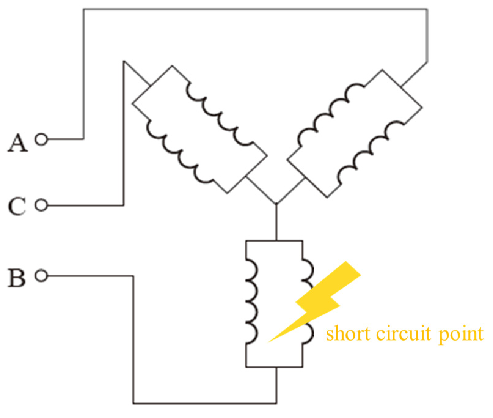
A pumped storage generator is a specialized hydroelectric power generation equipment that can convert electrical energy into potential energy of water during off-peak periods of grid load, and subsequently convert this potential energy back into electrical energy to supply the grid during peak hours. In the stator windings of a pumped storage generator, there are also three-phase windings labeled as A, B, and C. Each of these phases carries different currents and voltages, collectively driving the operation of the generator. When a short-circuit fault occurs in the stator windings of a pumped storage generator, the current in the faulty phase (one or more of A, B, C) will surge significantly, causing the temperature of the windings to rise and potentially leading to their burnout. Taking the stator windings of a pumped storage hydroelectric generator connected in a “Y” configuration as an example, when an inter-turn short-circuit occurs in the B-phase of the stator windings, an additional circulating current is generated. The location of the stator winding short-circuit fault in the pumped storage hydroelectric generator is illustrated in Figure 1.

Figure 1.
The location of the stator winding short-circuit fault in the pumped storage generator.
Assuming ζ represents the ratio between the number of short-circuited turns in each phase and the total number of turns in that phase, a higher value of ζ indicates a more severe inter-turn fault in the stator of the generator. The voltage equation can be expressed as
where represents the phase voltage column vector of the stator and rotor when an inter-turn short-circuit occurs in the stator windings; R denotes the resistance of the stator and rotor for the inter-turn short-circuit; i represents the three-phase current of the stator and rotor resulting from the inter-turn short-circuit; p denotes the differential operator; and Ψ represents the flux linkage matrix of the stator and rotor with the inter-turn short-circuit, which can be calculated according to Equation (2)
where Lls and Llr represent the leakage inductance per phase of the stator and rotor windings, respectively; Ls and Lr represent the self-inductance per phase of the stator and rotor windings, respectively; Lms and Lmr represent the main inductances of the stator and rotor windings, respectively; Ils and Ilr represent the line currents of the stator and rotor windings, respectively; Is and Ir represent the zero-sequence currents of the stator and rotor windings, respectively; and Ims and Imr represent the three-phase currents of the stator and rotor windings, respectively.
The electromagnetic torque equation is expressed as
where Te represents the electromagnetic torque supplied by the generator; np represents the number of pole pairs; θr represents the electrical angle; itr represents the instantaneous state rate of change of the three-phase current i; itds represents the instantaneous time derivative of the three-phase current i; and T denotes the matrix transpose operation.
The electromagnetic motion equation is expressed as
where TL represents the driving torque supplied by the generator; J represents the moment of inertia; D represents the damping coefficient; and ωr represents the electrical angular velocity.
By combining the voltage and current equations of the pumped storage hydroelectric generator with the voltage and current waveform coefficients of the generator, the results of extracting the characteristic signals of stator inter-turn short-circuit faults are obtained as follows:
where a and b represent the voltage and current waveform coefficients, respectively.
2.2. Time-Domain Transformation of Short-Circuit Fault Signals Based on STFT
In pumped storage hydroelectric generators, the nonlinear magnetic circuit characteristics caused by stator inter-turn short-circuit faults can lead to an increase in current harmonic components. By performing spectral analysis on the current signals, changes in these current harmonic components can be observed. However, in practical fault diagnosis, the time-domain representation of signals is more intuitive and easier to understand. Therefore, to obtain the time-domain representation of stator inter-turn short-circuit fault signals, this paper utilizes STFT to convert frequency-domain signals into time-domain signals, thereby acquiring the spectrum diagram of stator short-circuit faults in pumped storage hydroelectric generators. By applying STFT to transform the three-phase current signals under stator short-circuit fault conditions in the time domain, the transformation formula from three-phase currents to two-phase currents is expressed as
where I represents the magnitude of the two-phase current; and iα and iβ represent the magnitudes of two types of phase currents derived from the three-phase currents. Based on the transformed two-phase currents, time–frequency conversion of the stator short-circuit fault signals in pumped storage hydroelectric generators is performed. Using STFT for time-domain transformation of stator short-circuit fault signals and utilizing the transformation results for stator short-circuit fault identification can improve the accuracy of fault identification.
STFT provides joint time–frequency distribution information. The STFT of a time-varying signal s(t) can be expressed as
where the window function satisfies .
STFT is essentially a process of computing the Fourier transform of a series of signal segments. Its principle is illustrated in Figure 2 and can be expressed as g(τ − t)s(τ), where τ represents the length of the intercepted time segment, and it satisfies .
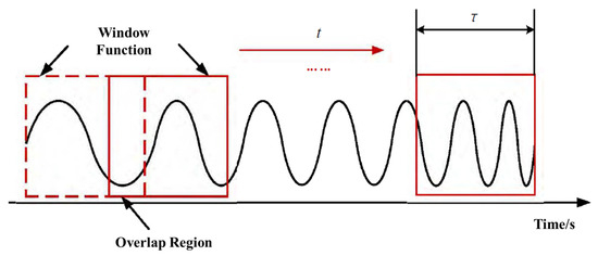
Figure 2.
Illustration of STFT.
From Figure 2, it can be observed that the fixed nature of the STFT window solidifies the time–frequency resolution across the entire time–frequency plane, making STFT unsuitable for directly representing nonstationary signals with rapidly changing rotational speeds. Therefore, this paper proposes an improvement to the traditional STFT algorithm. By varying the window orientation, the peak detection method and the linear chirplet transform (LCT) are respectively combined with the traditional model to extract the instantaneous frequency of time-varying current signals. Selecting the optimal window size is a crucial step because it directly impacts the balance between the frequency resolution and temporal resolution after transformation. The window size directly determines the frequency resolution. A larger window provides better frequency resolution because more data points are used to calculate each frequency component, but this comes at the cost of reduced temporal resolution. Conversely, a smaller window offers higher temporal resolution, enabling more precise localization of fault occurrence, but at the expense of decreased frequency resolution.
The current signals generated by inter-turn short-circuit faults in the stator windings of pumped storage generators typically contain multiple frequency components, including the fundamental frequency and harmonic components. Therefore, selecting a window size that can capture these important frequency components is essential. A larger window size increases computational complexity and reduces the real-time performance of the algorithm. Hence, when choosing the window size, it is necessary to strike a balance between computational efficiency and system real-time requirements.
Methods for determining the optimal window size include empirical approaches and experimental methods. In this paper, experiments are conducted on actual or simulated systems by trying out different window sizes and observing their impact on fault diagnosis results. The window size is adjusted based on the experimental results until satisfactory diagnostic performance is achieved.
The peak detection method is an instantaneous frequency extraction algorithm based on energy peaks. It estimates the instantaneous frequency by searching for the coordinate positions of peaks on the time–frequency map. Its expression is as follows:
The formula expresses the estimated instantaneous frequency of the k-th component as , where represents the time–frequency coefficients after the time–frequency transformation of the signal. According to the principle of the peak detection method, the higher the energy concentration in the time–frequency representation, the higher the accuracy of the instantaneous frequency extracted by the peak detection method.
The LCT method rotates the window only once, making it effective in processing linear frequency modulated (LFM) signals. Its expression is given as
In the formula, hα(τ − t) represents the rotated window function, which can be expressed as:
where z represents the rotation operator. Converting the time-domain signals of two-phase currents during stator short-circuit faults into frequency-domain signals through STFT is an efficient signal transformation algorithm. During the transformation of stator fault signals, converting the time-domain signals of stator two-phase currents into frequency-domain signals helps process a large amount of data in a short time, improving the speed of signal processing. For the same signal length, the calculated spectral error is also smaller, and the computational process is more concise. The following steps can be taken to obtain the spectrogram of the stator two-phase current time-domain signals converted into frequency-domain signals:
Step 1: During sampling, stator three-phase current time-domain signals with equal time intervals need to be collected and converted into two-phase currents.
Step 2: To satisfy the butterfly operation rule, 2n points of the stator two-phase current time-domain signals are intercepted.
Step 3: Use STFT to convert the stator two-phase current time-domain signals into frequency-domain signals.
Step 4: Determine the frequency-domain range of the stator two-phase currents. Let dt be the time-domain sampling interval, and be the entire frequency-domain range, which is divided into 2n parts.
Step 5: Create a spectrogram of the stator two-phase currents. The vertical axis represents the signal amplitude, and the horizontal axis represents the frequency. By mapping each frequency to its corresponding amplitude on the coordinates, a spectrogram of the stator two-phase currents can be obtained.
3. Fault Diagnosis Model Based on the Improved SVDD
3.1. Introduction to the Traditional SVDD Model
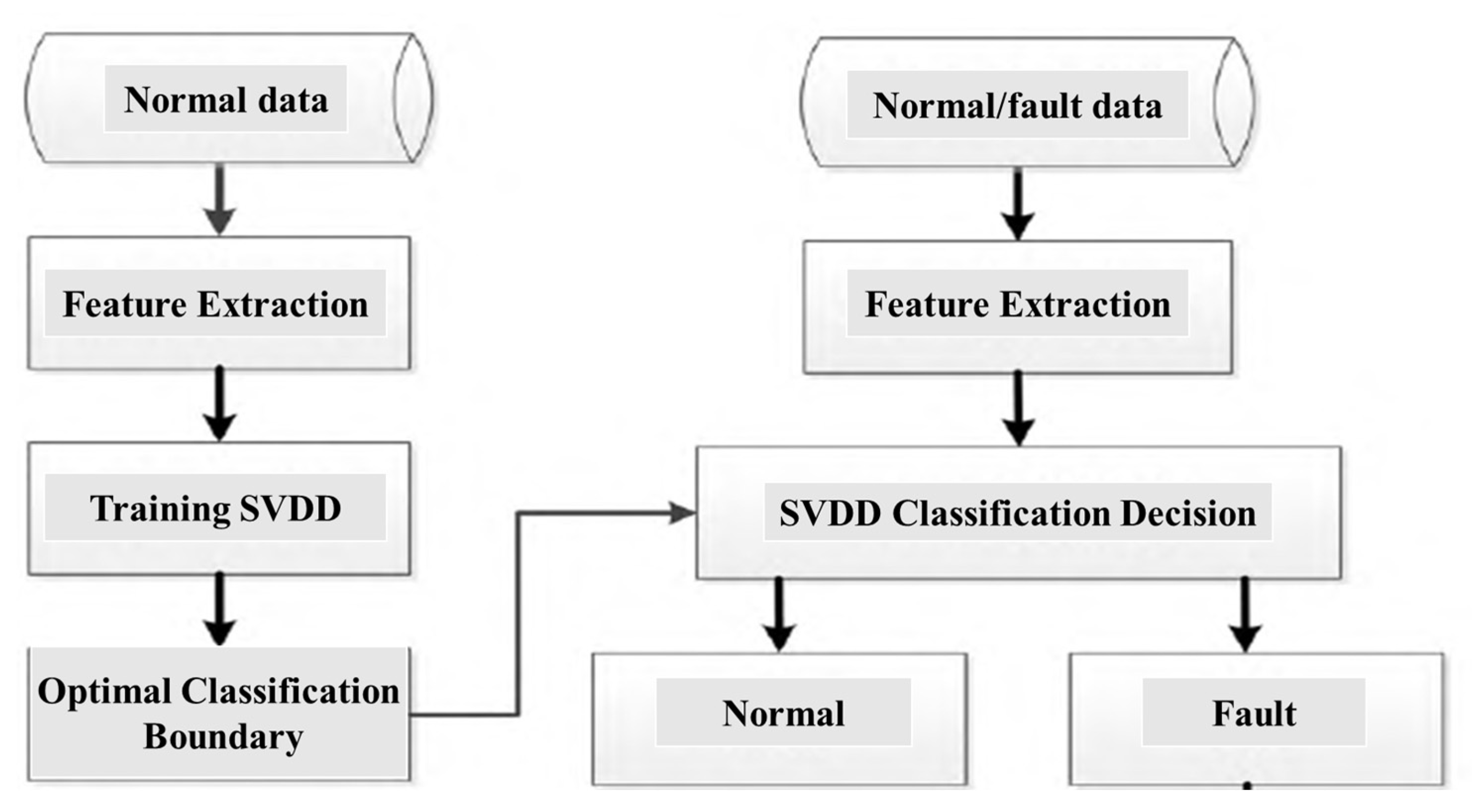
Figure 3 presents the workflow diagram of the traditional SVDD. During the model training phase, “normal” class samples are input. Firstly, spectral analysis is performed on these samples to extract features and form feature vectors. Subsequently, these feature vectors are used to train the SVDD model, resulting in an optimal closed classification boundary. As a one-class classifier, SVDD only requires “normal” class samples to construct the classification boundary, thereby significantly reducing the difficulty of acquiring “fault” class samples during the training phase.
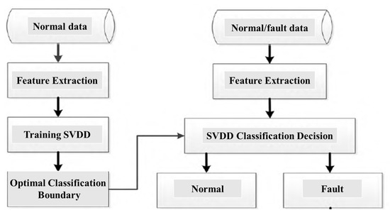
Figure 3.
The workflow diagram of the traditional SVDD.
Pumped storage power units spend most of their time in normal operating conditions, meaning that “normal” is a long-term and stable state, while “fault” is a random and short-lived state. Therefore, in actual use, it is often difficult to obtain sufficient “fault” class samples for training detection models. The SVDD classifier, when used for “fault” detection of the unit, only requires “normal” class samples to complete the training of the optimal classification boundary.
For the set of “normal” class samples , the SVDD classification model can be represented by
where c represents the center of the closed hypersphere classification surface of SVDD, and r is the corresponding radius; and ξi and C are the slack variable and penalty factor, respectively, set to avoid overfitting. Since the training sample set in real-world environments often does not conform to a spherical distribution, SVDD introduces a kernel function to map the training samples into a higher-dimensional space, enabling them to exhibit a spherical distribution in this higher-dimensional space. The commonly used kernel function is the radial basis function (RBF) shown in (12)
where σ represents the kernel parameter. By introducing Lagrange multipliers and the kernel function into (11), it can be transformed into the dual form shown in (13)
where serves as an indicator for support vectors. When > 0, the corresponding xi represents a support vector on the hypersphere. Based on all the support vectors obtained from (13), the optimal hypersphere of SVDD can be derived as
After obtaining the optimal hypersphere, for any test sample x∗, we can simply determine whether it belongs to the “normal” or “faulty” category based on whether its distance from the center of the hypersphere is greater than the radius. The SVDD decision function is
If f(x∗) ≤ 0, meaning x∗ lies within the hypersphere, it indicates that x∗ belongs to the “normal” class; if f(x∗) > 0, meaning x∗ lies outside the hypersphere, it indicates that x∗ belongs to the “faulty” class.
3.2. Improvement Mechanism of SVDD
The traditional SVDD algorithm is a classic one-class classification algorithm. Its classification principle involves finding the optimal solution for a hypersphere that can encompass all positive class samples, thereby obtaining the optimal classification boundary among data samples to achieve the goal of classification and recognition. The SVDD algorithm relies solely on positive class samples for training, without the need for other samples. However, precisely because the SVDD algorithm considers only one class of samples during classification and ignores the influence of a small number of negative class samples on the decision boundary, the optimized classification decision boundary often leans toward the majority class, i.e., the positive class samples, resulting in poor overall generalization performance of the algorithm. Consequently, when used as a fault detection model for classification, the algorithm exhibits insufficient detection range and is prone to missed alarms. Therefore, the traditional SVDD algorithm has certain limitations as a fault diagnosis classifier for pumped storage units.
This paper proposes an improvement to the traditional SVDD algorithm that effectively addresses the issues of classification boundary bias and low generalization performance caused by the algorithm’s exclusive focus on positive class samples, leading to insufficient detection accuracy. The design philosophy of the improved SVDD algorithm can be summarized as follows. Based on the SVDD algorithm, we utilize negative class samples to adjust the classification boundary. By introducing penalty factors for both positive and negative class samples in the training data set, the algorithm considers all samples, causing the classification boundary to shift toward the negative class samples, thereby enhancing the algorithm’s generalization performance and improving the detection accuracy of the model. This algorithm further improves the performance of the traditional SVDD algorithm in handling imbalanced data, making it more suitable for addressing fault classification and recognition problems under imbalanced data conditions. Next, we will introduce the mathematical mechanism of the improved SVDD algorithm based on the mathematical principles of the traditional SVDD algorithm. Specifically, we will add penalty factors for both positive and negative class samples in the traditional SVDD algorithm, yielding the following mathematical model expression:
where C1 and C2 represent the introduced penalty constants, which serve to control the magnitudes of the loss functions for normal samples and negative class samples, respectively; and ξi and ξm are penalty factors that regulate the distances between positive class samples and negative class samples, adjust the position of the classification boundary, and enhance the generalization performance of the algorithm. This is the key improvement compared to the traditional SVDD algorithm.
As can be seen from the above formula, the improved SVDD algorithm considers all data samples. By incorporating penalty factors, the algorithm’s classification boundary moves closer to the midpoint between the two classes of samples, thereby enhancing its generalization performance. As a result, the algorithm’s classification performance is improved, and the detection accuracy for minority class samples is also significantly increased.
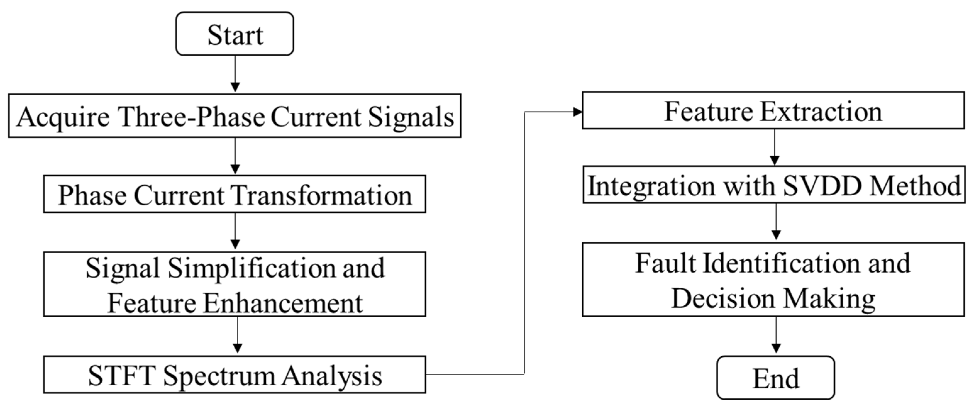
Finally, a detailed flowchart of detection and identification of inter-turn short circuit fault in pumped storage generator stator windings is given in Figure 4.
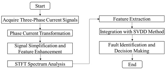
Figure 4.
Detection and identification of inter-turn short circuit fault in pumped storage generator stator windings.
4. Case Study and Discussion
4.1. Introduction to Test Information
This paper selects a medium-sized pumped storage power station as the experimental object. This pumped storage power station has a total of four pumped storage generators numbered from 1 to 6, each with a rated capacity of 30 kVA. The specific parameters of the pumped storage generators are shown in Table 1.

Table 1.
Technical parameters of pumped storage units.
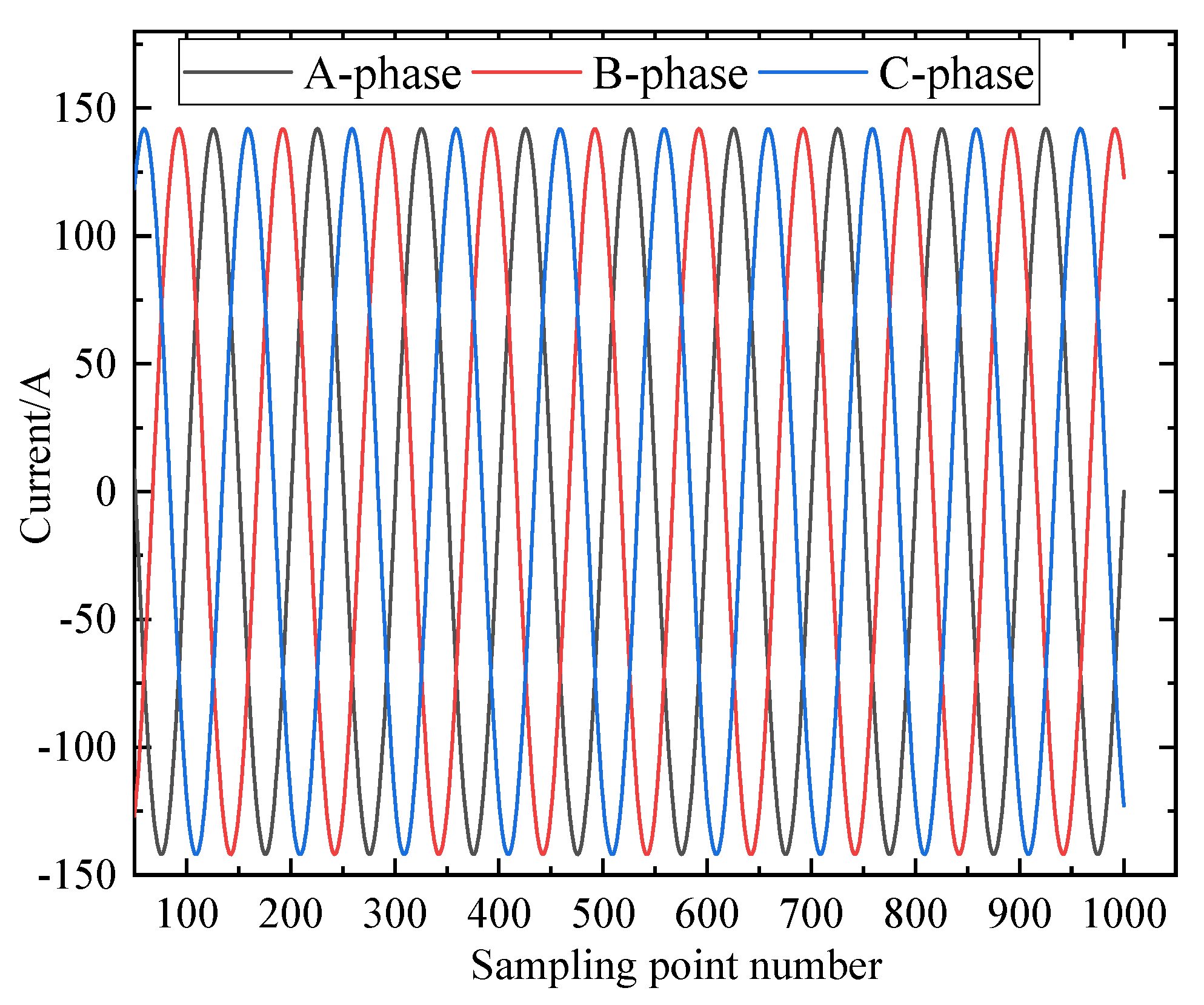
This paper experimentally captures the current waveforms of normal and stator A-phase winding minor and severe short-circuit faults in pumped storage generators. The normal current waveform of the pumped storage generator is shown in Figure 5.
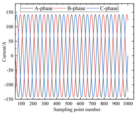
Figure 5.
The normal current waveform of the pumped storage generator.
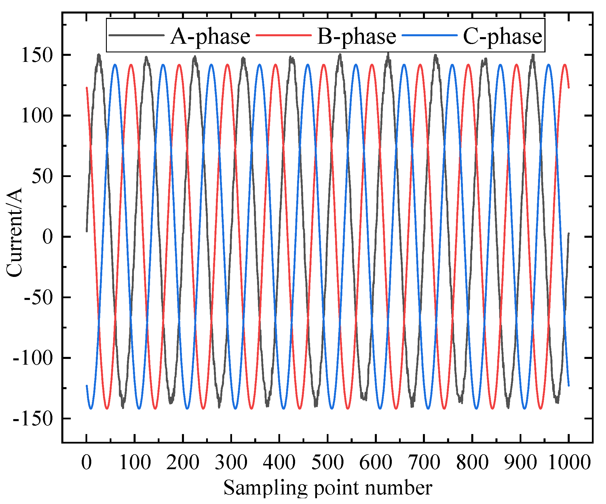
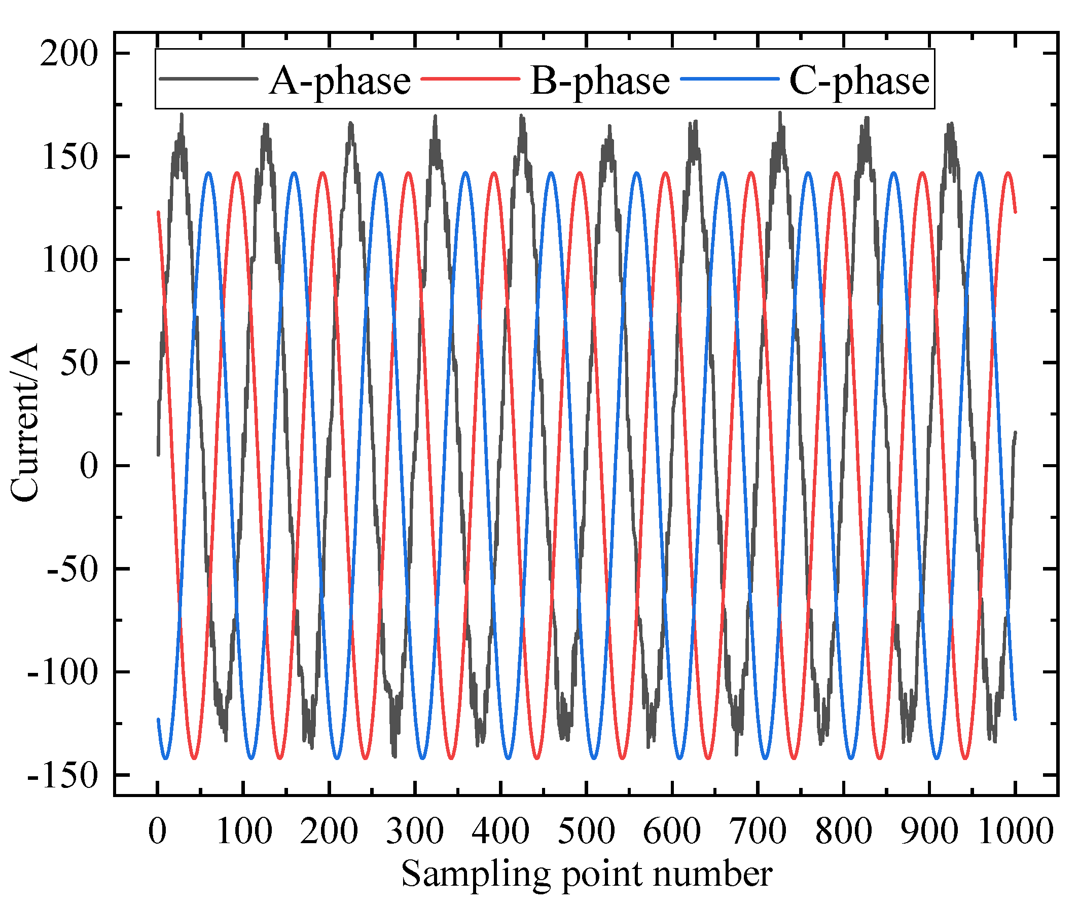
The current waveforms of slight and severe short-circuit faults in the stator of pumped storage generators are shown in Figure 6 and Figure 7.
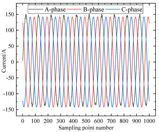
Figure 6.
The current waveforms of slight short-circuit faults.
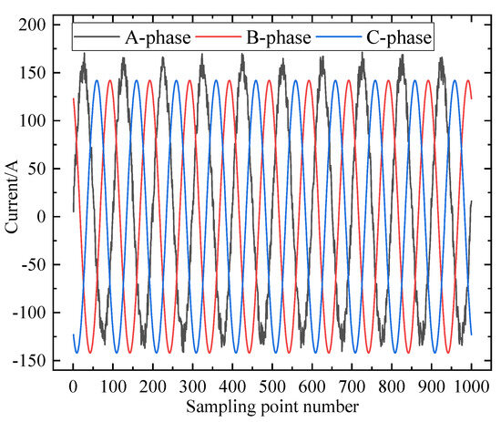
Figure 7.
The current waveforms of severe short-circuit faults.
As can be seen from Figure 5 and Figure 6, the stator current waveform under normal conditions of the generator exhibits a three-phase balanced state. When a relatively minor interturn short circuit occurs in the stator winding, the time-domain waveform of the stator three-phase current undergoes minimal changes, making it difficult to intuitively identify the fault condition, thus increasing the difficulty in diagnosing interturn faults in the stator winding. To address this, it is necessary to obtain the frequency spectrum under slight fault conditions through STFT to achieve precise fault diagnosis.
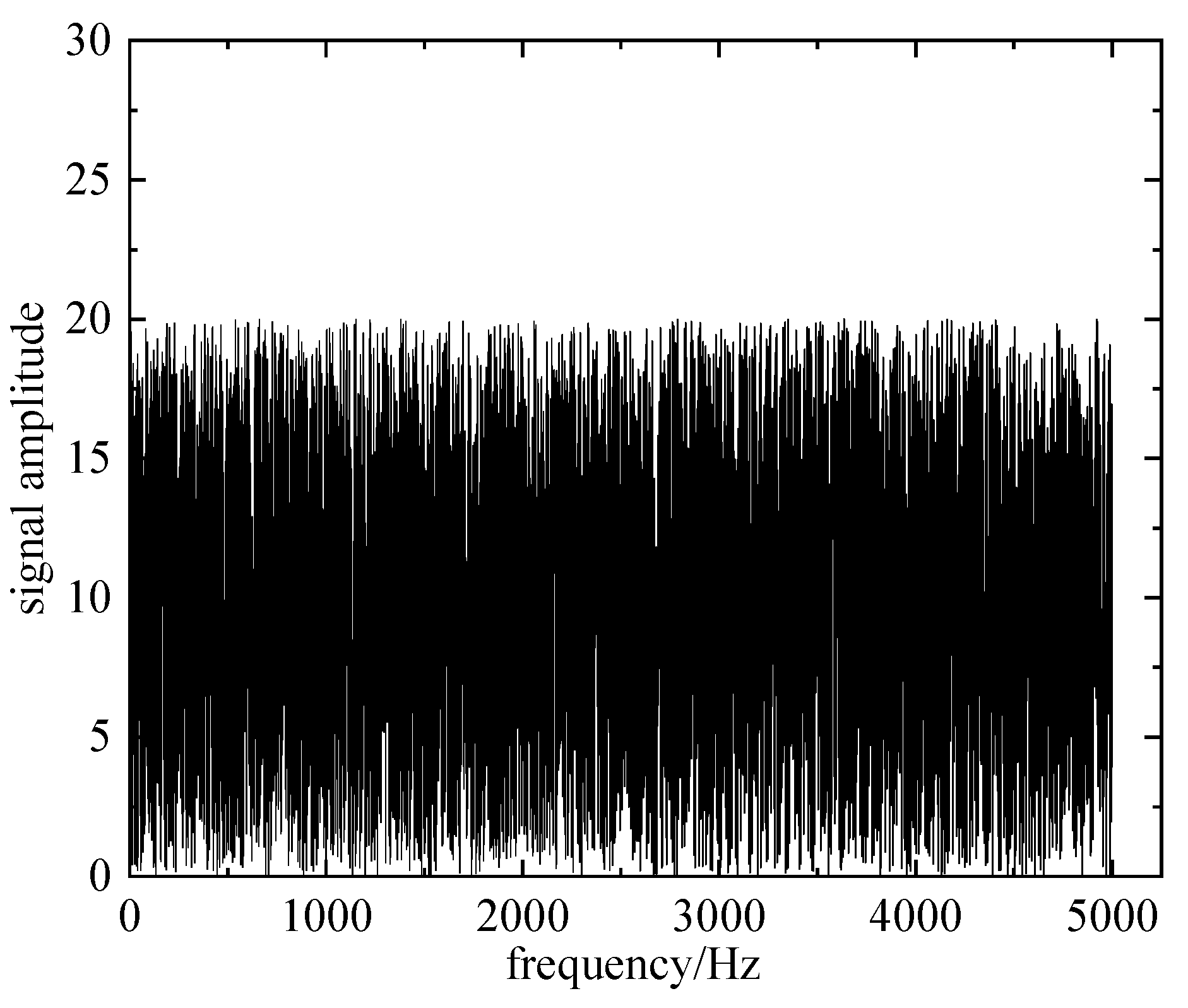
The STFT algorithm employed in this paper is used to acquire the spectral characteristics of both normal and stator fault conditions in pumped storage generators. The acquired waveform diagrams of stator fault currents in two types of pumped storage generators are converted into frequency-domain signals. The comparative frequency-domain representation of a normal pumped storage generator and a generator with a slight short circuit fault in the stator winding phase A is shown in Figure 8 and Figure 9. When a pumped storage generator operates normally, its electrical signals often contain multiple frequency components, including the fundamental frequency and its harmonic components. These signals of different frequencies manifest as multiple distinct peaks in the frequency-domain representation, making the graph appear more complex. As a component of the power system, the operation of a pumped storage generator is influenced by various factors such as changes in grid load and adjustments to the unit’s operating state. These dynamic changes can lead to nonstationary characteristics of the electrical signals in the frequency domain, further complicating the frequency-domain representation. During actual measurements, due to limitations in the accuracy of measurement equipment and interference from factors such as environmental noise, the signals obtained may contain certain errors and noise. These errors and noise can manifest as disordered spectral components in the frequency-domain representation. These factors contribute to the somewhat cluttered and unclear appearance of Figure 8 and Figure 9.
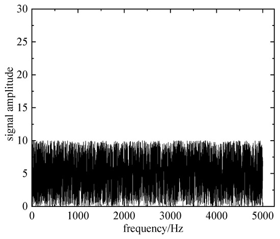
Figure 8.
Frequency-domain representation of a normal pumped storage generator.
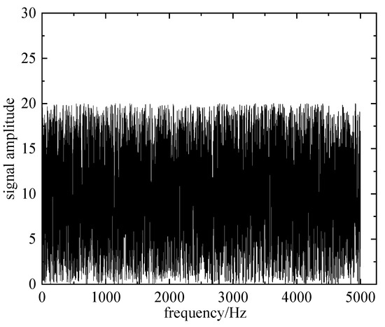
Figure 9.
Frequency-domain representation of a generator with a slight short circuit fault.
4.2. Comparative Algorithm and Experimental Result Analysis
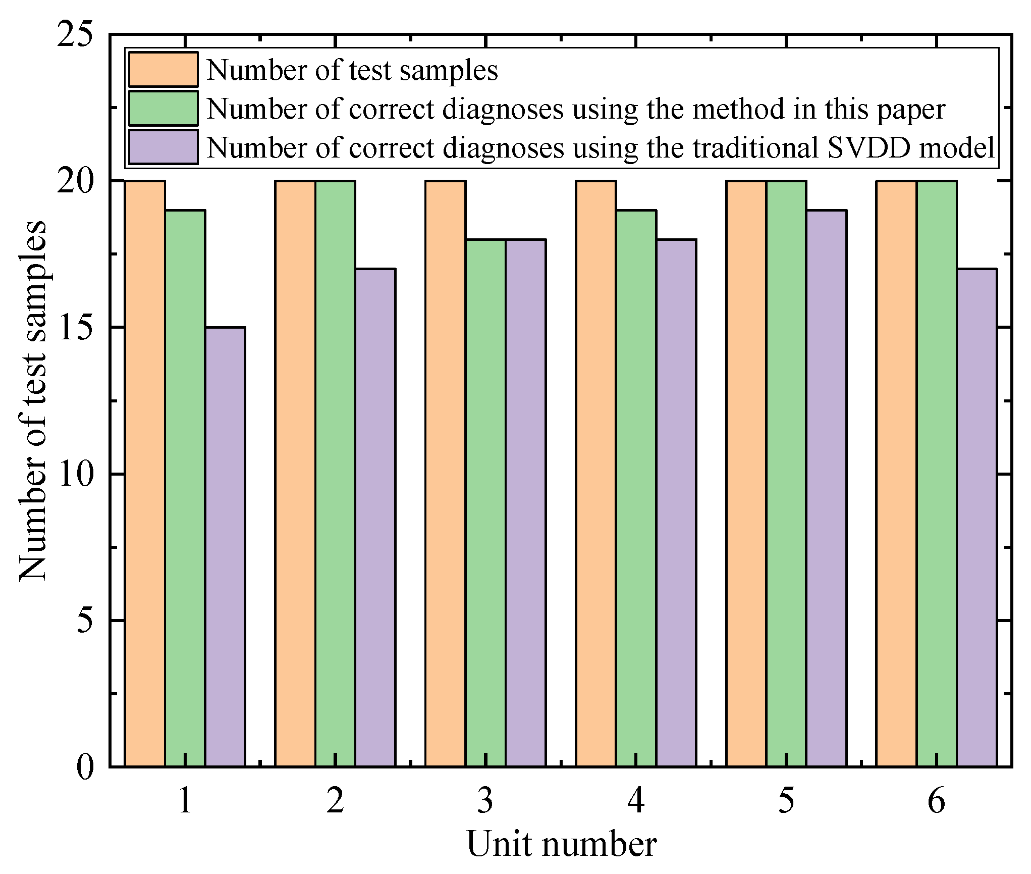
The sample set is input into the improved SVDD network, where the input is the transformed FFT spectrum results of the stator’s two-phase currents, and the output is the diagnosis result. The diagnosis results correspond one-to-one with the faults defined in the aforementioned fault diagnosis model. The experimental results for stator faults in pumped storage generators are presented in Table 2. Here, to further illustrate the superiority of the proposed algorithm, a comparison is made with the traditional SVDD model. Using stator fault data from pumped storage units as negative samples and normal operating data samples from the units as positive samples, simulations are conducted. The data set for testing comprises 100 positive samples and 10 negative samples, resulting in a positive-to-negative sample ratio of 10:1. The SVDD algorithm is used to perform classification and recognition simulations on this test data set. The SVDD algorithm employs a Gaussian kernel function with a kernel radius of 3 and a penalty constant of 10. As can be clearly seen in Figure 10, unlike traditional SVM algorithms, the SVDD algorithm functions as a one-class classifier. Since it focuses solely on the positive samples, there is no need for the few negative samples to participate in the formation of the decision boundary. This results in the optimized classification decision boundary being significantly biased toward the positive samples, thereby compromising the overall generalization performance of the algorithm and ultimately leading to insufficient detection accuracy and range.
Table 2.
Comparison of diagnosis method accuracies under different data sample sizes.
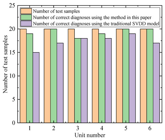
Figure 10.
Comparison results of fault diagnosis accuracy among different models.
To further illustrate the effectiveness and feasibility of the method proposed in this paper, the following tables show the comparison of accuracy among different diagnostic methods.
From Table 2 and Table 3, it can be observed that as the number of data samples increases, the fault diagnosis accuracy of each method improves; and as the noise interference increases, the fault diagnosis accuracy of each method decreases. However, compared to other conventional methods, the proposed method in this paper still achieves the highest fault diagnosis accuracy. Under small data samples, the proposed method can improve the accuracy by up to 7.2%; under strong noise interference, the fault diagnosis accuracy of the proposed method remains above 90%, and compared to conventional methods, the fault diagnosis accuracy can be improved by up to 6.9%. STFT is capable of processing nonstationary signals by segmenting the signal through sliding windows and applying Fourier transform within each window, thereby capturing the time–frequency characteristics of the signal. This feature makes STFT particularly suitable for analyzing dynamic operational data of equipment such as pumped storage units, whose signal characteristics may vary over time. In contrast, although deep learning models such as convolutional neural networks excel in feature extraction, they typically require a large amount of data for training to optimize weights and parameters, and for specific types of nonstationary signals, more complex network structures and longer training times may be needed. SVDD is a boundary-based method that distinguishes between normal and abnormal data by constructing a hypersphere around normal data points. This method exhibits good robustness to noise and outliers in the data, as outliers typically lie outside the hypersphere and do not affect its construction. In strong noise environments, other methods (such as EMD-SVM, SOM neural networks, and random forests) may be susceptible to noise interference, leading to blurred classification boundaries or model overfitting, thereby reducing fault diagnosis accuracy. For small data samples, SVDD has relatively low model complexity and is easier to learn effective classification boundaries from limited data. In contrast, deep learning models generally require a large amount of data to avoid overfitting and optimize model parameters during training. In small sample cases, the performance of deep learning models may be limited because they cannot fully learn the inherent features of the data.
Table 3.
Comparison of diagnosis method accuracies under different noise interference levels.
The proposed method is applied to different types of pumped storage units and various fault types to verify its wide applicability. Here, a total of four types of units were used, namely, four-machine, three-machine, reversible, and coaxial rotary pumped storage units. The fault types mainly include stator faults and rotor faults. The accuracy of fault diagnosis is detailed in Table 4.
Table 4.
Diagnostic accuracy for different faults in various types of units.
Upon observing Table 4, it can be discerned that the proposed method in this paper achieves a diagnostic accuracy of over 95.5% for different faults in various types of units. The STFT and SVDD algorithms each have their unique strengths in signal processing and data analysis. Specifically, STFT excels at extracting time–frequency features from signals, while SVDD is adept at detecting anomalies and performing classification. By combining these two algorithms into a hybrid approach, we can leverage their respective advantages to achieve precise identification of stator and rotor faults in pumped storage units. The improved STFT-SVDD hybrid algorithm is not limited by the type of pumped storage unit, making it applicable to a wide range of units. This is because the core of the algorithm lies in signal processing and data analysis, rather than the physical structure of the units. The algorithm is capable of recognizing multiple types of stator and rotor faults, such as unbalance, cracks, and looseness, which manifest as distinct frequency components and energy distributions in the signals. By extracting these features through STFT and inputting them into the SVDD model, precise fault classification and identification can be achieved. Therefore, the improved STFT-SVDD hybrid algorithm offers high real-time performance and accuracy, enabling real-time monitoring and diagnosis of faults during unit operation. The relatively low computational complexity of STFT and SVDD gives them an advantage in processing real-time data or large-scale data sets. In contrast, deep learning models may require longer training times and computational resources. In summary, the superior performance of the STFT-SVDD method in stator fault disturbance analysis of pumped storage units can be attributed to its adaptability in feature extraction, noise robustness, small sample learning ability, and computational efficiency. These advantages make this method particularly useful in complex, dynamic, and potentially noisy industrial environments.
5. Conclusions
As pumped-storage power units are complex electromechanical devices, their stator fault diagnosis and maintenance require highly specialized technical knowledge and experience. Pumped-storage power stations are often located in remote areas, posing difficulties and high costs for operation and maintenance. Additionally, the monitoring and early warning mechanisms during unit operation also need continuous improvement. To address these issues, this paper presents a stator fault diagnosis method for pumped storage generators based on a hybrid algorithm combining an improved STFT with SVDD. An in-depth study is conducted on the common inter-turn short circuit faults in the stator windings of pumped storage generators. By constructing a fault model for inter-turn short circuits in stator windings and analyzing the electrical and magnetic states associated with such faults in detail, this paper provides strong support for the safe and stable operation of pumped storage generators.
Through analysis, under small data samples, the precision of the method proposed in this paper can be improved by up to 7.2%. Even under strong noise interference, the fault diagnosis accuracy of the proposed method remains above 90%, and compared to conventional methods, the fault diagnosis accuracy can be improved by up to 6.9%. This indicates that the proposed method possesses excellent noise robustness and small sample learning ability, making it effective in complex, dynamic, and noisy environments.
In the future, with the rapid development of sensor technology and the Internet of Things, pumped-storage power units will be able to collect more diversified operational data. Consequently, researching how to efficiently fuse multisource information to enhance the accuracy and reliability of stator fault diagnosis will become a crucial direction. By integrating various signals such as vibration, temperature, current, and voltage, a more comprehensive system for evaluating the health status of the unit can be established, enabling early warning and precise localization of stator faults.
On the other hand, the emergence of cloud computing, big data, and other technologies has made real-time online monitoring and remote fault diagnosis feasible. Future research can focus on building a cloud-based remote monitoring platform for pumped-storage power units, enabling real-time monitoring and data analysis of the unit’s operational status. Through this remote monitoring platform, stator faults can be detected and addressed promptly, improving the unit’s reliability and availability. Additionally, big data analysis techniques can be leveraged to uncover potential patterns and failure modes within the unit’s operational data, providing a more scientific basis for fault diagnosis.
Author Contributions
Conceptualization, J.B., X.L., B.D., X.Y., B.C., Y.Z., J.Z., Z.W. and H.Z.; software, J.B., X.L., B.D., X.Y., B.C., Y.Z., J.Z., Z.W. and H.Z.; writing—original draft preparation, J.B., X.L., B.D., X.Y., B.C., Y.Z., J.Z., Z.W. and H.Z. All authors have read and agreed to the published version of the manuscript.
Funding
This research was funded by Science and Technology Project of Inner Mongolia Electric Power (Group) Co., Ltd.: Research on Multi-source Data Fusion and Analysis Technology for Insulation Condition Sensing and Operation & Maintenance Business of Large-scale Pumped Storage Units (No. 2024-4-46).
Data Availability Statement
The data presented in this study are available on request from the corresponding author.
Conflicts of Interest
Authors J.B., X.L., B.D., X.Y., B.C., Y.Z., J.Z., Y.Z., J.Z. and Z.W. was employed by Inner Mongolia Power (Group) Co., Ltd. The funders had no role in the design of the study; in the collection, analyses, or interpretation of data; in the writing of the manuscript; or in the decision to publish the results.
References
- Chazarra, M.; Pérez-Díaz, J.I.; García-González, J. Optimal Joint Energy and Secondary Regulation Reserve Hourly Scheduling of Variable Speed Pumped Storage Hydropower Plants. IEEE Trans. Power Syst. 2018, 33, 103–115. [Google Scholar] [CrossRef]
- Yang, L.; Li, H.; Zhang, H.; Wu, Q.; Cao, X. Stochastic-Distributionally Robust Frequency-Constrained Optimal Planning for an Isolated Microgrid. IEEE Trans. Sustain. Energy 2024, 1–15. [Google Scholar] [CrossRef]
- Yang, L.; Xu, Y.; Zhou, J.; Sun, H. Distributionally Robust Frequency Constrained Scheduling for an Integrated Electricity-Gas System. IEEE Trans. Smart Grid 2022, 13, 2730–2743. [Google Scholar] [CrossRef]
- Joseph, A.; Chelliah, T.R. A Review of Power Electronic Converters for Variable Speed Pumped Storage Plants: Configurations, Operational Challenges, and Future Scopes. IEEE J. Emerg. Sel. Top. Power Electron. 2018, 6, 103–119. [Google Scholar] [CrossRef]
- Kumada, A.; Nakamura, T.; Hidaka, K.; Tsuboi, Y.; Yoshimitsu, T. Potential distribution on the stress grading system of high-voltage rotating machines—I measuring system. IEEE Trans. Dielectr. Electr. Insul. 2015, 22, 3163–3169. [Google Scholar] [CrossRef]
- Kogan, V.; Nindra, B. Investigation of high voltage stator winding vibrations in full-scale slot model. In Proceedings of the Electrical Insulation Conference and Electrical Manufacturing and Coil Winding Conference, Rosemont, IL, USA, 25 September 1997; IEEE: New York, NY, USA, 1997; pp. 155–166. [Google Scholar]
- Zhang, Y.; Zhang, Q.; Hong, C.; Hou, Z.; Chen, J.; Di, H.; Zhang, Z.; Li, H.; Wu, M.; Lu, T.; et al. Treatment of wear and loosening at the end of the stator winding of the generator-motor in Tianhuangping Pumped Storage Power Station. Hydropower Pumped Storage 2017, 3, 17–20. [Google Scholar]
- Jia, Z.; Xia, Y.; Deng, Y.; Peng, X.; Guan, Z.; Wang, L. Dynamic analysis and detection of loosening of stator slot wedges in large generators. Proc. CSEE 2011, 31, 107–113. [Google Scholar]
- Shao, W.; Zhang, X.; Guo, Y. Research on eliminating insulation damage of generator stator bars. Electr. Power Equip. Manag. 2019, 2, 66–68. [Google Scholar]
- Zhao, Y.J.; Li, C.S.; Fu, W.L.; Yu, T.; Chen, H. A modified variational mode decomposition method based on envelope nesting and multi-criteria evaluation. J. Sound Vib. 2019, 468, 115099. [Google Scholar] [CrossRef]
- Shao, Y. Research on Data-Driven Fault Diagnosis Algorithm for Rolling Bearings. Master’s Thesis, Shandong University, Jinan, China, 2021. [Google Scholar]
- Chen, J. Research on Intelligent Fault Diagnosis Algorithm for Rotating Machinery Based on Deep Learning. Master’s Thesis, Beijing Jiaotong University, Beijing, China, 2021. [Google Scholar]
- Nayana, R.; Geethanjali, P. Analysis of statistical time-domain features effectiveness in identification of bearing faults from vibration signal. IEEE Sens. J. 2017, 17, 5618–5625. [Google Scholar] [CrossRef]
- Luo, M.; Li, C.S.; Zhang, X.; Li, R.; An, X. Compound feature selection and parameter optimization of ELM for fault diagnosis of rolling element bearings. ISA Trans. 2016, 65, 556–566. [Google Scholar] [CrossRef]
- Li, X.; Xu, Z.; Xiong, W.; Wang, Z.; Tan, J. A method for bearing fault diagnosis based on deep metric learning. J. Vib. Shock. 2020, 39, 25–31. [Google Scholar]
- Xiao, Q. Overview of Machinery Fault Diagnosis Methods Based on Machine Learning Theory. Mod. Manuf. Eng. 2021, 7, 148–161. [Google Scholar]
- Wu, C.; Jiang, P.; Feng, F.; Chen, T.; Chen, X. Fault diagnosis of gearbox based on one-dimensional convolutional neural network. J. Vib. Shock. 2018, 37, 51–56. [Google Scholar]
- Yuan, Y. Early Fault Diagnosis Strategy for Rolling Bearings Based on Deep Learning. Sci. Technol. Innov. 2022, 5, 181–184. [Google Scholar]
- Peng, C.; Li, F.; Jiang, J. Overview of Fault Diagnosis and Prediction Methods Based on Deep Learning. Mod. Electron. Tech. 2022, 45, 111–120. [Google Scholar]
- Hoang, D.T.; Kang, H.J. A survey on Deep Learning based bearing fault diagnosis. Neurocomputing 2019, 335, 327–335. [Google Scholar] [CrossRef]
- Peng, D.; Liu, Z.; Wang, H. A Novel Deeper One-Dimensional CNN With Residual Learning for Fault Diagnosis of Wheelset Bearings in High-Speed Trains. IEEE Access 2018, 7, 10278–10293. [Google Scholar] [CrossRef]
- Liu, H.; Zhou, J.Z.; Zheng, Y. Fault diagnosis of rolling bearings with recurrent neural network-based autoencoders. ISA Trans. 2018, 77, 167–178. [Google Scholar] [CrossRef]
- Pan, Y.; Mei, F.; Miao, H.; Zheng, J.; Zhu, K.; Sha, H. An Approach for HVCB Mechanical Fault Diagnosis Based on a Deep Belief Network and a Transfer Learning Strategy. J. Electr. Eng. Technol. 2019, 14, 407–419. [Google Scholar] [CrossRef]
- Qiao, J.; Yin, X.; Wang, Y.; Lu, Q.; Tan, L.; Zhu, L. A Rotor Ground Fault Protection Method Based on Injection Principle for Variable Speed Pumped Storage Generator-Motor. IEEE Trans. Power Deliv. 2023, 38, 1159–1168. [Google Scholar] [CrossRef]
- Joseph, A.; Chelliah, T.R.; Selvaraj, R.; Lee, K.-B. Fault Diagnosis and Fault-Tolerant Control of Megawatt Power Electronic Converter-Fed Large-Rated Asynchronous Hydrogenerator. IEEE J. Emerg. Sel. Top. Power Electron. 2019, 7, 2403–2416. [Google Scholar] [CrossRef]
- Qiao, J.; Yin, X.; Wang, Y.; Yin, X.; Lu, Q.; Zhu, L.; Zhang, Q. Faulty Phase Selection and Location Method of Rotor Ground Fault for Variable Speed Pumped Storage Generator-Motor. IEEE Trans. Power Deliv. 2023, 38, 4253–4262. [Google Scholar] [CrossRef]
- Joseph, A.; Desingu, K.; Semwal, R.R.; Chelliah, T.R.; Khare, D. Dynamic Performance of Pumping Mode of 250 MW Variable Speed Hydro-Generating Unit Subjected to Power and Control Circuit Faults. IEEE Trans. Energy Convers. 2018, 33, 430–441. [Google Scholar] [CrossRef]
- Sunal, C.E.; Dyo, V.; Velisavljevic, V. Review of Machine Learning Based Fault Detection for Centrifugal Pump Induction Motors. IEEE Access 2022, 10, 71344–71355. [Google Scholar] [CrossRef]
- Qi, P.; Li, Y.; Ma, M.; Wu, Y.; Lu, W. Research on the Vibration Characteristics of Pumped Storage Unit Stator Core Based on Fiber Optic Sensing. IEEE Trans. Energy Convers. 2023, 38, 2179–2190. [Google Scholar] [CrossRef]
- Rouabah, B.; Toubakh, H.; Djemai, M.; Ben-Brahim, L.; Ghandour, R. Fault Diagnosis Based Machine Learning and Fault Tolerant Control of Multicellular Converter Used in Photovoltaic Water Pumping System. IEEE Access 2023, 11, 39013–39023. [Google Scholar] [CrossRef]
- Qi, P.; Li, Y.; Ma, M.; Hao, P.; Yao, X.S. Interturn Short Circuit Detection of Pumped Storage Unit Based on Optical Fiber Weak Magnetic Sensing. IEEE Trans. Power Electron. 2024, 39, 8732–8743. [Google Scholar] [CrossRef]
- Zhang, Y.; Liu, T.; Yuan, K.; Lv, T. High Reliable Lead Wire System of the Rotor Winding in Pumped Storage Power Stations. IEEE Access 2023, 11, 82390–82399. [Google Scholar] [CrossRef]


Disclaimer/Publisher’s Note: The statements, opinions and data contained in all publications are solely those of the individual author(s) and contributor(s) and not of MDPI and/or the editor(s). MDPI and/or the editor(s) disclaim responsibility for any injury to people or property resulting from any ideas, methods, instructions or products referred to in the content. |
© 2024 by the authors. Licensee MDPI, Basel, Switzerland. This article is an open access article distributed under the terms and conditions of the Creative Commons Attribution (CC BY) license (https://creativecommons.org/licenses/by/4.0/).