Article

Study of Helium Irradiation Effect on Al6061 Alloy Fabricated by Additive Friction Stir Deposition

1
Department of Mechanical & Industrial Engineering, Louisiana State University, Baton Rouge, LA 70803, USA
2
Department of Mechanical Engineering, Southern University and A&M College, Baton Rouge, LA 70813, USA
3
Department of Computer Science, Southern University and A&M College, Baton Rouge, LA 70813, USA
4
Department of Mathematics and Computer Science, & Engineering Technology, Elizabeth City State University, Elizabeth City, NC 27909, USA
5
Los Alamos National Laboratory, Los Alamos, NM 87545, USA
*
Authors to whom correspondence should be addressed.
Processes 2024, 12(10), 2144; https://doi.org/10.3390/pr12102144
Submission received: 26 August 2024 / Revised: 16 September 2024 / Accepted: 29 September 2024 / Published: 2 October 2024
(This article belongs to the Special Issue Composite Materials Processing, Modeling and Simulation)

Abstract

:
Additive friction stir deposition (AFS-D) is considered a productive method of additive manufacturing (AM) due to its ability to produce dense mechanical parts at a faster deposition rate compared to other AM methods. Al6061 alloy finds extensive application in aerospace and nuclear engineering; nevertheless, exposure to radiation or high-energy particles over time tends to deteriorate their mechanical performance. However, the effect of radiation on the components manufactured using the AFS-D method is still unexamined. In this work, samples from the as-fabricated Al6061 alloy, by AFS-D, and the Al6061 feedstock rod were irradiated with He+ ions to 10 dpa at ambient temperature. The microstructural and mechanical changes induced by irradiation of He+ were examined using a scanning electron microscope (SEM), energy-dispersive X-ray spectroscopy (EDS), transmission electron microscopy (TEM), and nanoindentation. This study demonstrates that, at 10 dpa of irradiation damage, the feedstock Al6061 produced a bigger size of He bubbles than the AFS-D Al6061. Nanoindentation analysis revealed that both the feedstock Al6061 and AFS-D Al6061 samples have experienced radiation-induced hardening. These studies provide a valuable understanding of the microstructural and mechanical performance of AFS-D materials in radiation environments, offering essential data for the selection of materials and processing methods for potential application in aerospace and nuclear engineering.

1. Introduction

A wide range of applications are possible for the Al6061 alloy due to its exceptional mechanical properties such as ductility, high specific strength, wear resistance, light weight, heat resistance, and corrosion resistance [1,2,3,4]. It has been widely utilized in aerospace, marine, automobile, and many other industries. Production of aluminum alloy parts from traditional methods like casting and wrought processing are strongly impacted by the cooling rate, which leads to unique microstructures and mechanical properties. Compared to traditional methods, additive manufacturing (AM) is promising as it can print complex parts on demand using computer-aided design fed to high-precision printers, without additional machining and tooling. Aluminum alloys are usually built layer by layer in AM, mostly using techniques such as direct energy deposition (DED) [5] and laser powder bed fusion (L-PBF) [6]. However, the parts produced from the AM technique are generally not cost-efficient due to the slow deposition rate. Moreover, defects, such as pores and cracks due to material fusion, impact the mechanical performance [7,8], which limits the Al alloy types suitable for DED and L-PBF processes.
Additive friction stir deposition (AFS-D), also termed as MELD additive manufacturing, is a novel technology that can produce highly dense and large-sized parts compared to other AM methods [9,10]. The parts reported in this study were fabricated using a MELD L3 system, which has a building volume of 1150 mm × 590 mm × 595 mm. The AFS-D employs heat produced by friction between the spinning tool and feedstock rod with the previously printed layer or the substrate, to make feedstock plastically deform and bring it to a plastic or pasty state. The temperature generated by friction heat should remain below the melting temperature of the feedstock during printing, which makes the process a solid-state AM method. Due to this, the AFS-D is capable of printing different types of Al alloys with low residual stresses compared with the previously mentioned DED and L-PBF AM methods, which are fusion-based processes [11].
The primary mechanisms involved in grain refinement are severe plastic deformation and recrystallization. The rotating feedstock rod is gradually pushed towards the substrate. As a result, heat is generated by the friction between the rotating feedstock and the substrate/tool. This heat softens the feedstock material (plastically deforms) filling the space between the deposition tool surface and substrate. The MELD tool starts extruding the materials once the actuation force and torque settle. Finally, the deposition tool head starts depositing the material based on the instructions provided by G-code. The grain size of the deposited material becomes smaller compared with the original feedstock sample due to severe plastic deformation and recrystallization during the fabrication process [12]. The stirring process applies significant mechanical stress to the material, which significantly deforms and breaks the grains into smaller sizes. Meanwhile, the heat produced by the stirring causes recrystallization of the grain, which forms finer grains throughout the AFS-D parts. As a result, the AFS-D parts have unique mechanical and physical properties, which draw interests from the additive manufacturing research community. Recently, Bhavesh et al. [13] prepared Al6061 using friction stir powder AM and found microstructures consisting of tiny sub-grains with an approximate size of 6.1 ± 0.2 μm in the third layer. Ben et al. [14] found that Al6061 prepared from the AFS-D exhibits dynamic recrystallization, resulting in the refined, equiaxed grain structure with predominantly high-angle grain boundaries. The investigation performed by Phillips et al. [15] discovered that raising tool parameters such as the actuator feed rate, rotation, and traversal speed enhances the hardness of Al6061. Despite a growing number of studies on Al6061 fabricated by AM methods, the majority of previous research was concentrated on finding the relationship between the mechanical properties and the distribution of grain structures after deposition. However, an irradiation damage study of Al6061 fabricated from the AFS-D method has not been performed. Prior irradiation research has mostly examined how irradiation affects aluminum alloys made through conventional manufacturing techniques. To the best of the authors’ knowledge, this study is the first to investigate the irradiation effects of Al6061, fabricated through the AFS-D method. The Al6061 is an aerospace material that is expected to work under space irradiation [16]. Moreover, it is also used in research nuclear reactors as a potential cladding material due to its excellent corrosion resistance, low neutron absorption, and high thermal conductivity [17,18,19,20].
Therefore, it is crucial to study the effect of irradiation on its microstructure, which helps to understand how irradiation influences the mechanical performance and provides information on how it behaves in harsh conditions.
In this work, the irradiation effect on the Al6061 alloy made with the AFS-D method was investigated. The feedstock samples and the AFS-D Al6061 samples were irradiated with 200 KeV He+ ions to the peak damage of 10 displacements per atom (dpa) at ambient temperature. The microstructures were characterized by transmission electron microscopy (TEM), scanning electron microscopy (SEM), and energy-dispersive X-ray spectroscopy (EDS). Nanoindentation was used to provide an estimation of the mechanical properties before and after irradiation. The results provide insights on the service life estimation of these AFS-D-processed alloys under a harsh irradiation environment.

2. Experimental and Simulation Methods

Square rods of Al6061 (508 mm × 9.5 mm × 9.5 mm), with the elemental composition of Al97.54Si0.44Mg1.63Fe0.16Cu0.23 (wt.%), are used as feedstock for 3D printing. The tensile strength of T6-6061 aluminum is approximately 290 MPa (42 ksi) and a yield strength of around 240 MPa (35 ksi), with an elongation at break of 8–10%. In terms of thermal properties, it has a thermal conductivity of about 167 W/m·K and a melting point of approximately 585 °C. Figure 1 presents a schematic diagram of the AFS-D process.
AFS-D operates through frictional heating and severe plastic deformation induced by a rotating tool, which causes the material to soften below its melting point. The softened material is then plastically extruded and deposited layer by layer, enabling the fabrication of bulk structures with strong metallurgical bonding. This solid-state additive manufacturing technique promotes fine microstructure evolution and minimizes defects commonly associated with fusion-based processes. A MELD L3 machine produced by Meld Manufacturing Corporation located in Christiansburg, VA, USA was employed to print the Al6061 samples with the following processing parameters: 300 RPM as a tool rotating speed, 152.4 mm/min as a feedstock feed rate, and 254 mm/min as a tool traversing speed. With a layer thickness of 1.5 mm, a total of 34 layers are needed to form a block of 50 mm in height. The length of the deposited block is around 180 mm, and the width of the deposition track is around 40 mm. The outer layer of the feedstock rod is covered with graphite to prevent jamming inside the deposition tool. The friction force stemmed from the spinning of the feedstock rod against the substrate deforms the rod plastically, making it easier to be deposited into a plasticized state. The friction force-induced heat generation is around 4 to 7 kW. Figure 2 shows a macro image of the square-shaped feedstock rod following the AFSD process. The overall working mechanism of the L3 machine is succinctly explained in a previous publication [21].
The as-deposited Al6061 and feedstock rods were sectioned using an electrical discharge machine into 5 mm × 5 mm squares with a thickness (height) of 0.3 mm. The sample surfaces were mechanically polished using SiC grit papers up to P-4000 and diamond slurry of 3 and 1 µm on the polishing cloth. For the final polishing step, samples were kept in the VibroMet Vibratory Polisher for more than 24 h to give a mirror finish using a 0.05 µm alumina solution on the polishing cloth. The implantation of He ions on the mirror-finished feedstock and the AFS-D Al was performed using 200 keV He+ ions to a fluence of 3 × 10¹⁷ ions/cm2 at ambient temperature on the 200 kV Danfysik ion implanter of Los Alamos National Laboratory. The He ion irradiation damage and implantation depth profiles of the Al6061 alloy were predicted using the SRIM Monte Carlo simulator [22], as shown in Figure 3. The SRIM profile shows that the irradiation-induced peak damage is located around 900 nm, while the He implantation peak is located around 950 nm. Threshold displacement energy of 27 eV was used for Al while other minor elements were ignored in the SRIM calculations.
The surface morphology after irradiation was measured with SEM (Ametek. Model: APOLLO XL, Berwyn, PA, USA). The TEM specimens were prepared with a ThermoFisher Helios 600 Nanolab Ga+ FIB/SEM equipment, at CINT Gateway at LANL. A 30 kV accelerating voltage was first applied to lift out the TEM foils, followed by thinning with decreasing voltages to make a wedge. To minimize the FIB-induced damages, the lamellas were subsequently polished with 8 keV and 5 keV Ga ions, then the final cleanup was performed with 2 keV Ga ions. The under- and over-focus technique under TEM was utilized to characterize the cavities after He ion irradiation. A nanoindentation hardness test was performed on the polished top surfaces before and after irradiation using the Nano Indenter G200 manufactured by Agilent Technologies Inc. (CA, USA). A Berkovich-tipped nano indenter was used for nanoindentation testing to assess the effect of irradiation hardening. The hardness depth profile was ascertained using the constant stiffness measurement (CSM) mode. Twenty-five indents were performed in a 5 × 5 matrix on each sample to obtain the average modulus and depth-dependent hardness with a peak loading penetration depth of 1000 nm.

3. Results and Discussions

3.1. Surface Morphology and Microstructure Characterization

The surface morphology was investigated for both the feedstock and the AFS-D samples after irradiation, and grain structures were not discernible, as demonstrated in Figure 4. Figure 4a,b show the surface morphology of feedstock with varying magnifications, while Figure 4c,d demonstrate that of the AFS-D samples. With a close observation, in comparison with the feedstock samples showing a smooth surface (Figure 4a) and very tiny particles (indicated by black arrows in Figure 4b), the AFS-D samples exhibited distinctly rougher surfaces (Figure 4c) with larger precipitates (highlighted by black arrows in Figure 4d). To evaluate the composition distribution on the surfaces depicted in Figure 4, EDS mapping analysis was employed and is illustrated in Figure 5. As per Figure 5, the precipitates seen in Figure 4 predominantly consist of the segregation of Si and Mg elements. Zeng et al.’s earlier study deduced that the Si-Mg segregation mainly comprises the Mg2Si phase [23]. Furthermore, Zeng et al. [23] found that the feedstock samples contained a high density of precipitates compared to the AFS-D samples, as evidenced by the X-ray diffraction study. The precipitates in the AFS-D samples appear to have a larger size while their density is lower compared to those in the feedstock samples, suggesting that the precipitates have gone through a long growth phase. The variation in precipitates between the AFS-D Al6061 alloy sample and the feedstock counterpart is hypothesized to result from the high temperature generated due to the friction stir process and the plastic deformation of material during deposition.
The He bubbles produced by irradiation are characterized by TEM in different focus conditions. The under-focused image gives the best contrast for the He bubble features. Figure 6 refers to a peak band of bubble formation at around 970 nm from the surface, which is consistent with the SRIM prediction of the peak He concentration region. The bubbles are bigger in the middle of the band (region (B) in Figure 6 and smaller at the two sides of the band, (A) and (C). Note that the central region labeled (B) is the intersection between the vacancy, refer to the damage depth profile in Figure 3, and the interstitial region, refer to the He depth profile; that is where the bubble could grow bigger, more than the two other regions. Moreover, one can note that region (A) in Figure 6 is wider than region (C). The former belongs to the damage tail, and the latter would belong to the end of the range. Combining these observations, we believe that the bubble size distribution is mainly affected by the concentration of deposited He ions in the material and the vacancy distribution, where vacancies helped further the growth of the He bubbles. The defect distribution, revealed by TEM, appears consistent with the evolution of He ions with depth, as generated by SRIM. The distinct size of the bubbles is a synergic result of irradiation defects and the He ion stopping range in the peak band. The peak damage region (around 900 nm) provides more vacancies induced by irradiation for the formation of bubbles. Furthermore, the irradiated He ions reached the peak damage region and accumulated to form more enlarged faceted bubbles. As the distance away from the peak depth, both the damage and He content decrease, resulting in smaller bubbles at the side of the bubble band. Similar faceted larger dense He bubble morphology was also reported by Zhang et al. [24] after He implantation of 1.5 × 10¹⁷ He ions/cm2 on Al metal at room temperature, which is exactly half of the He fluence used in this experiment, suggesting a certain level of resemblance in bubble formation properties under varying fluence.
Similarly, Figure 7 shows TEM images of AFS-D Al6061. It is found that the AFS-D Al6061 has He bubbles formed at an 800–1000 nm depth from the surface. Figure 7 reveals the He bubbles’ size in the AFS-D Al6061 is smaller than that observed in the feedstock, and these smaller bubbles exhibit a homogeneous distribution throughout the microstructure. The observed inconsistency in the size of the helium bubbles’ formation between the AFS-D and the feedstock could have been attributed to the difference in grain sizes of pristine Al6061. As reported by Zeng et al. [23], the AFS-D as-deposited Al6061 exhibits a smaller grain size, approximately 6 µm, while the feedstock exhibits a larger grain size, measuring around 165 µm. Smaller grain sizes increase the number of grain boundaries (GBs) or the interfaces between neighboring crystalline grains. It is widely accepted that heterointerfaces and GBs serve as effective regions in the material for sinking and trapping irradiation-induced point defects and thus improve the irradiation tolerance of materials [25,26,27,28,29]. The capacity of GBs to annihilate point defects and defect clusters caused by collision cascades in materials has also been confirmed by atomistic simulations [26,30,31]. The large grain size provides the longer path for the diffusion of defects, promoting the coalescence of He bubbles in the feedstock samples. It was assumed that the imperfect hexagonal shape of He bubbles in the feedstock was an outcome of the diffusion of defects during the irradiation along the grain boundary or dislocation lines [24,32].

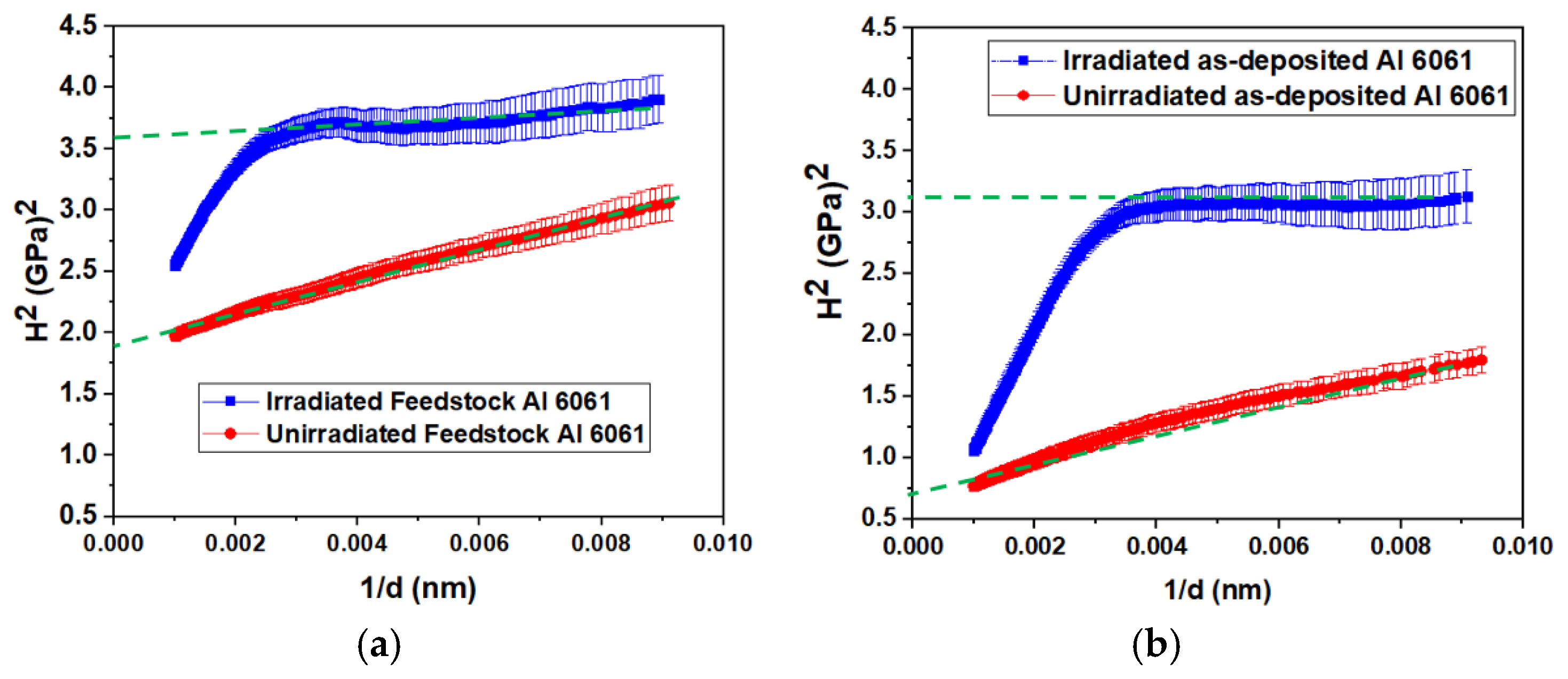
3.2. Nanoindentation Hardness Test

To examine the impact of He irradiation on the hardness, a nanoindentation hardness test was performed for both the AFS-D and the feedstock Al6061 alloys. The results of the hardness tests on the unirradiated and irradiated samples are illustrated in Figure 8a and Figure 8b, respectively. Comparing the nanoindentation curves before and after irradiation for both samples, pronounced irradiation hardening was observed. The nano-hardness value is high around the surface for both samples, and it keeps dropping with the increasing depth, which is identified as the indentation size effect (ISE). To extract reasonable hardness from the indentation curves, the Nix–Gao model (NGM) [33] was implemented to eliminate the ISE. The following function can be used to represent the hardness (H) measured by nanoindentation, according to the NGM relation:
H = H 0 1 + h * d
where h* represents the characteristic length of the indenter tip, d is the depth of the indent, and H 0 is the bulk-equivalent hardness at infinite depth. By plotting H2 versus 1/d as shown in Figure 9a for the Al6061 feedstock sample and Figure 9b for the AFS-D Al6061, the intercept of the linear extrapolation of the data points yields the equivalent hardness in bulk. In the case of the unirradiated samples, linear fitting was used on the whole set of data points due to the uniform microstructures and linear trend in the hardness test. However, for the irradiated samples with a limited damage region, the H2 vs. 1/d plots show a clear inflection in the hardness around 0.0033 (i.e., 300 nm). To avoid this effect, the linear fitting on the irradiated samples was only applied to the data within the first ~300 nm. From the graph, it can be visualized that both unirradiated samples have a linear relationship between H2 and 1/d, which was demonstrated by the ISE. The H 0 for the irradiated and unirradiated samples are shown in Table 1 and were determined by fitting the hardness data from Equation (1). Before irradiation, the feedstock Al6061 nano-hardness is 1.36 GPa and AFS-D as-deposited Al6061 is 0.83 GPa. The density and size of precipitates inside a material’s microstructure are important factors when it comes to the material nano-hardness.
After irradiation, the hardness for the feedstock sample increased by 0.52 GPa, and the increase for the as-deposited Al6061 was 0.91 GPa. According to the classic hardening models given by either Friedel–Kroupa–Hirsch (FKH) [34] or Dispersed Barrier Hardening (DBH) [35], the hardness is associated with the size and density of the obstacle for dislocation movement. After irradiation in this study, the most unyielding obstacles in our experiments are the He bubbles and precipitates. Since the bubble size in the feedstock Al6061 is extremely high with significant overlap, the quantitative analysis may not be reliable and was not applied. The qualitative visualization of precipitation and He bubbles is summarized in Table 2.
Despite the variations in the precipitation and He bubbles in terms of size and density, the feedstock and the AFS-D samples after irradiation seem to have a similar level of nano-hardness (1.88 GPa and 1.74 GPa, respectively). The feedstock Al6061 is characterized by a small size and high density of precipitation, whereas the AFS-D Al6061 has a large size and low density of precipitation. Similarly, the feedstock Al6061 exhibits a large size and low-density He bubbles, whereas the as-deposited Al6061 has a small size and high-density helium bubbles. It is interesting to note that the two samples’ post-irradiation nano-hardness was very similar since the opposing characteristics of precipitation and He bubbles in terms of size and density appear to balance each other’s effects. The previous literature shows that bubbles generated by He irradiation block the dislocation motion and increase the hardness of irradiated materials [36,37,38]. Cui et al. [36] used 200 keV He ions to implant modified novel high-silicon (MNHS) martensitic steel and found that He bubbles and dislocation loops are the primary causes of irradiation-induced hardening. Cao et al. [39] demonstrated the influence of precipitation on irradiation hardening. They utilized two high-entropy alloy (HEA) samples of (CoCrFeNi)94Ti2Al4, one in its initial cast state with no precipitates and the other aged to produce large precipitates. These two HEA samples were irradiated at room temperature with Au ions to 10, 25, and 29 dpa. The hardness of HEA with no precipitates increased by more than 30% after irradiation. For the sample containing more precipitates, the irradiation hardening was minimum due to disordering as well as dissolving of precipitates by the irradiation.
The structure of precipitates is diverse and complicated, containing coherent, semi-coherent, and incoherent interfaces. While this work provides valuable qualitative insights into the relation between nano-hardness and precipitates, it does not conclusively identify the precise mechanism responsible for the observed irradiation-hardening effect in AFS-D Al6061. Further investigation is needed to fully comprehend the irradiation-hardening effect due to the presence of these pre-existing precipitates.
If more doses of irradiation are applied to the material, the previously formed He bubbles will trap more He atoms and expand the He bubble because of coalescence forming voids and cavities. If bubbles were bigger than a critical radius, they would obviously have a negative impact on the properties of the material, such as swelling and embrittlement [40,41]. This will result in the depletion of structural material properties and shorten the lifetime of the material after irradiation [42,43]. The irradiation-induced hardening is less severe in the AFS-D Al6061 compared with its original feedstock Al6061 sample. This is confirmed by the nature of bubble formation between these two samples. The sizes of He bubbles are significantly smaller and are homogeneously distributed in AFS-D Al6061, possibly meaning a high irradiation-tolerance capacity. The parts produced from the AFS-D show some promising properties compared to the original feedstock material. It is expected that the AFS-D methods can be applied to other material systems where high irradiation-tolerance properties are required. These findings highlight some of the possible causes of the hardening effect due to irradiation caused by He ions in the feedstock and the AFS-D Al6061 samples. However, to fully understand the He bubble generation and its impact on the mechanical performance of AM alloys, additional research on the dislocation mechanism is required for more AM-fabricated samples. Furthermore, more studies with atomic-scale simulation are required to provide more information on the behavior of helium segregation at GBs and He bubble effects on the mechanical and structural performance of materials, especially on those fabricated from the AFS-D method where a large shear stress is applied.

4. Conclusions

In this study, the feedstock rod and the AFS-D Al6061 samples were irradiated at room temperature with helium ions to a dose of 10 dpa. The microstructural and mechanical changes after irradiation have been investigated based on the bubble formation on both samples. The TEM analysis revealed that the helium bubble size is much larger in the feedstock sample of Al6061 than the AFS-D Al6061 sample. TEM images of the feedstock sample show that bigger size bubbles formed around the center (700–900 nm depth) and smaller-sized bubbles at two end sides; their size distribution along the depth suggests the joint effects of the vacancy and He depth distribution. The change in hardening between the feedstock and the AFS-D Al6061 after irradiation is caused by the variation in He bubble formation and is possibly due to pre-existing precipitates. This variation in bubble formations suggests that additional factors such as dislocation or defect mobility could influence the result and suggest further investigation is necessary to clarify the understanding of irradiation effects. Overall, the AFS-D Al6061 has a smaller size of He bubbles, showing its better tolerance towards irradiation compared to the feedstock Al6061. Therefore, parts developed from the AFS-D Al6061 are highly promising and the AFS-D method could be an excellent choice for developing structural materials in the future for different applications.

Author Contributions

Conceptualization, U.B. and S.G.; Methodology, U.B., H.D., Y.W. and S.G.; Validation, C.Z. and H.K.; Formal analysis, S.Y., A.K., P.Z. and M.R.C.; Investigation, H.D. and C.Z.; Writing—original draft, U.B.; Writing—review & editing, S.Y., Y.W. and S.G.; Supervision, S.Y., Y.W. and S.G. All authors have read and agreed to the published version of the manuscript.

Funding

This work was partially supported by the US National Science Foundation under Grant OIA-1946231 and Louisiana Board of Regents for the Louisiana Materials Design Alliance (LAMDA). Partial support is also provided by NNSA MSIPP Consortium Award DE-NA0004112, NSF Award 2216805, and DOE Award DE-NA0004144. This work was performed, in part, at the Center for Integrated Nanotechnologies, an Office of Science User Facility operated for the U.S. Department of Energy (DOE) Office of Science. Los Alamos National Laboratory, an affirmative action equal opportunity employer, is managed by Triad National Security, LLC for the U.S. Department of Energy’s NNSA, under contract 89233218CNA000001.

Data Availability Statement

The original contributions presented in the study are included in the article, further inquiries can be directed to the corresponding author.

Conflicts of Interest

The authors declare no conflict of interest.

References

  1. Kumar, G.B.V.; Pramod, R.; Sekhar, C.G.; Kumar, G.P.; Bhanumurthy, T. Investigation of physical, mechanical and tribological properties of Al6061–ZrO2 nano-composites. Heliyon 2019, 5, e02858. [Google Scholar] [CrossRef] [PubMed]
  2. Karakoç, H.; Ovalı, İ.; Dündar, S.; Çıtak, R. Wear and mechanical properties of Al6061/SiC/B4C hybrid composites produced with powder metallurgy. J. Mater. Res. Technol. 2019, 8, 5348–5361. [Google Scholar]
  3. Ogunsanya, O.A.; Akinwande, A.A.; Balogun, O.A.; Romanovski, V. Mechanical and damping behavior of artificially aged Al6061/TiO2 reinforced composites for aerospace applications. Part. Sci. Technol. 2022, 41, 1–13. [Google Scholar]
  4. Aldwell, B.; Kelly, E.; Wall, R.; Amaldi, A.; O’Donnell, G.E. Machinability of Al6061 deposited with cold spray additive manufacturing. J. Therm. Spray Technol. 2017, 26, 1573–1584. [Google Scholar] [CrossRef]
  5. Carroll, B.E.; Palmer, T.A.; Beese, A.M. Anisotropic tensile behavior of Ti–6Al–4V components fabricated with directed energy deposition additive manufacturing. Acta Mater. 2015, 87, 309–320. [Google Scholar] [CrossRef]
  6. King, W.E.; Anderson, A.T.; Ferencz, R.M.; Hodge, N.E.; Kamath, C.; Khairallah, S.A.; Rubenchik, A.M. Laser powder bed fusion additive manufacturing of metals; physics, computational, and materials challenges. Appl. Phys. Rev. 2015, 2, 041304. [Google Scholar] [CrossRef]
  7. Gao, H.; Li, H. Friction additive manufacturing technology: A state-of-the-art survey. Adv. Mech. Eng. 2021, 13, 1–29. [Google Scholar] [CrossRef]
  8. Qu, M.; Guo, Q.; Escano, L.I.; Nabaa, A.; Hojjatzadeh, S.M.H.; Young, Z.A.; Chen, L. Controlling process instability for defect lean metal additive manufacturing. Nat. Commun. 2022, 13, 1079. [Google Scholar] [CrossRef]
  9. Griffiths, R.J.; Perry, M.E.J.; Sietins, J.M.; Zhu, Y.; Hardwick, N.; Cox, C.D.; Rauch, H.A.; Yu, H.Z. A perspective on solid-state additive manufacturing of aluminum matrix composites using MELD. J. Mater. Eng. Perform. 2019, 28, 648–656. [Google Scholar] [CrossRef]
  10. Yu, H.Z.; Jones, M.E.; Brady, G.W.; Griffiths, R.J.; Garcia, D.; Rauch, H.A.; Cox, C.D.; Hardwick, N. Non-beam-based metal additive manufacturing enabled by additive friction stir deposition. Scr. Mater. 2018, 153, 122–130. [Google Scholar] [CrossRef]
  11. Griffiths, R.J.; Petersen, D.T.; Garcia, D.; Yu, H.Z. Additive friction stir-enabled solid-state additive manufacturing for the repair of 7075 aluminum alloy. Appl. Sci. 2019, 9, 3486. [Google Scholar] [CrossRef]
  12. Perry, M.E.; Rauch, H.A.; Griffiths, R.J.; Garcia, D.; Sietins, J.M.; Zhu, Y.; Zhu, Y.; Yu, H.Z. Tracing plastic deformation path and concurrent grain refinement during additive friction stir deposition. Materialia 2021, 18, 101159. [Google Scholar] [CrossRef]
  13. Chaudhary, B.; Jain, N.K.; Murugesan, J.; Patel, V. Exploring temperature-controlled friction stir powder additive manufacturing process for multi-layer deposition of aluminum alloys. J. Mater. Res. Technol. 2022, 20, 260–268. [Google Scholar] [CrossRef]
  14. Rutherford, B.A.; Avery, D.Z.; Phillips, B.J.; Rao, H.M.; Doherty, K.J.; Allison, P.G.; Brewer, L.N.; Jordon, J.B. Effect of thermomechanical processing on fatigue behavior in solid-state additive manufacturing of Al-Mg-Si alloy. Metals 2020, 10, 947. [Google Scholar] [CrossRef]
  15. Phillips, B.J.; Avery, D.Z.; Liu, T.; Rodriguez, O.L.; Mason, C.J.T.; Jordon, J.B.; Brewer, L.N.; Allison, P.G. Microstructure-deformation relationship of additive friction stir-deposition Al–Mg–Si. Materialia 2019, 7, 100387. [Google Scholar] [CrossRef]
  16. Ni, K.; Ma, Q.; Wan, H.; Yang, B.; Ge, J.; Zhang, L.; Si, N. Effect of He+ fluence on surface morphology and ion-irradiation induced defect evolution in 7075 aluminum alloys. Mater. Res. Express 2018, 5, 026514. [Google Scholar] [CrossRef]
  17. Gussev, M.N.; Sridharan, N.; Babu, S.; Terrani, K.A. Influence of neutron irradiation on Al-6061 alloy produced via ultrasonic additive manufacturing. J. Nucl. Mater. 2021, 550, 152939. [Google Scholar] [CrossRef]
  18. Kim, Y.S.; Chae, H.; Berghe, S.V.D.; Leenaers, A.; Kuzminov, V.; Yacout, A. Aluminum cladding oxide growth prediction for high flux research reactors. J. Nucl. Mater. 2020, 529, 151926. [Google Scholar] [CrossRef]
  19. Mehta, A.; Zhou, L.; Huynh, T.; Park, S.; Hyer, H.; Song, S.; Bai, Y.; Imholte, D.D.; Woolstenhulme, N.E.; Wachs, D.M.; et al. Additive manufacturing and mechanical properties of the dense and crack free Zr-modified aluminum alloy 6061 fabricated by the laser-powder bed fusion. Addit. Manuf. 2021, 41, 101966. [Google Scholar] [CrossRef]
  20. Mehta, A.; Zhou, L.; Schulz, E.A.; Keiser, D.D.; Cole, J.I.; Sohn, Y. Microstructural characterization of AA6061 versus AA6061 HIP bonded cladding–cladding interface. J. Phase Equilibria Diffus. 2018, 39, 246–254. [Google Scholar] [CrossRef]
  21. Ghadimi, H.; Ding, H.; Emanet, S.; Talachian, M.; Cox, C.; Eller, M.; Guo, S. Hardness Distribution of Al2050 Parts Fabricated Using Additive Friction Stir Deposition. Materials 2023, 16, 1278. [Google Scholar] [CrossRef] [PubMed]
  22. Ziegler, J.F.; Ziegler, M.D.; Biersack, J.P. SRIM–The stopping and range of ions in matter (2010). Nucl. Instrum. Methods Phys. Res. Sect. B Beam Interact. Mater. At. 2010, 268, 1818–1823. [Google Scholar] [CrossRef]
  23. Zeng, C.; Ghadimi, H.; Ding, H.; Nemati, S.; Garbie, A.; Raush, J.; Guo, S. Microstructure Evolution of Al6061 Alloy Made by Additive Friction Stir Deposition. Materials 2022, 15, 3676. [Google Scholar] [CrossRef] [PubMed]
  24. Zhang, F.; Wang, X.; Wierschke, J.B.; Wang, L. Helium bubble evolution in ion irradiated Al/B4C metal metrix composite. Scr. Mater. 2015, 109, 28–33. [Google Scholar] [CrossRef]
  25. Demkowicz, M.; Misra, A.; Caro, A. The role of interface structure in controlling high helium concentrations. Curr. Opin. Solid State Mater. Sci. 2012, 16, 101–108. [Google Scholar] [CrossRef]
  26. Bai, X.-M.; Voter, A.F.; Hoagland, R.G.; Nastasi, M.; Uberuaga, B.P. Efficient annealing of radiation damage near grain boundaries via interstitial emission. Science 2010, 327, 1631–1634. [Google Scholar] [CrossRef]
  27. Shen, T.D.; Feng, S.; Tang, M.; Valdez, J.A.; Wang, Y.; Sickafus, K.E. Enhanced radiation tolerance in nanocrystalline MgGa2O4. Appl. Phys. Lett. 2007, 90, 263115. [Google Scholar] [CrossRef]
  28. Bringa, E.M.; Monk, J.D.; Caro, A.; Misra, A.; Zepeda-Ruiz, L.; Duchaineau, M.; Abraham, F.; Nastasi, M.; Picraux, S.T.; Wang, Y.Q.; et al. Are nanoporous materials radiation resistant? Nano Lett. 2012, 12, 3351–3355. [Google Scholar] [CrossRef]
  29. Zhuo, M.; Fu, E.; Yan, L.; Wang, Y.; Zhang, Y.; Dickerson, R.; Uberuaga, B.; Misra, A.; Nastasi, M.; Jia, Q. Interface-enhanced defect absorption between epitaxial anatase TiO2 film and single crystal SrTiO3. Scr. Mater. 2011, 65, 807–810. [Google Scholar] [CrossRef]
  30. Zhang, Y.; Huang, H.; Millett, P.C.; Tonks, M.; Wolf, D.; Phillpot, S.R. Atomistic study of grain boundary sink strength under prolonged electron irradiation. J. Nucl. Mater. 2012, 422, 69–76. [Google Scholar] [CrossRef]
  31. Vetterick, G.A.; Gruber, J.; Suri, P.K.; Baldwin, J.K.; Kirk, M.A.; Baldo, P.; Wang, Y.Q.; Misra, A.; Tucker, G.J.; Taheri, M.L. Achieving radiation tolerance through non-equilibrium grain boundary structures. Sci. Rep. 2017, 7, 1–9. [Google Scholar] [CrossRef] [PubMed]
  32. Wei, Q.; Li, N.; Sun, K.; Wang, L. The shape of bubbles in He-implanted Cu and Au. Scr. Mater. 2010, 63, 430–433. [Google Scholar] [CrossRef]
  33. Nix, W.D.; Gao, H. Indentation size effects in crystalline materials: A law for strain gradient plasticity. J. Mech. Phys. Solids 1998, 46, 411–425. [Google Scholar] [CrossRef]
  34. Kasada, R.; Takayama, Y.; Yabuuchi, K.; Kimura, A. A new approach to evaluate irradiation hardening of ion-irradiated ferritic alloys by nano-indentation techniques. Fusion Eng. Des. 2011, 86, 2658–2661. [Google Scholar] [CrossRef]
  35. Seeger, A.; Diehl, J.; Mader, S.; Rebstock, H. Work-hardening and work-softening of face-centred cubic metal crystals. Philos. Mag. 1957, 2, 323–350. [Google Scholar] [CrossRef]
  36. Cui, M.; Wang, J.; Wang, Z.; Shen, T.; Wei, K.; Yao, C.; Sun, J.; Gao, N.; Zhu, Y.; Pang, L.; et al. Helium irradiation induced hardening in MNHS steels. Nucl. Instrum. Methods Phys. Res. Sect. B Beam Interact. Mater. At. 2017, 406, 611–617. [Google Scholar] [CrossRef]
  37. Cui, M.; Shen, T.; Pang, L.; Zhu, Y.; Jin, P.; Liu, C.; Fang, X.; Wang, Z. He ion implantation induced He bubbles and hardness in tungsten. Nucl. Mater. Energy 2018, 15, 232–236. [Google Scholar] [CrossRef]
  38. Kong, F.; Qu, M.; Yan, S.; Zhang, A.; Peng, S.; Xue, J.; Wang, Y. Helium-induced hardening effect in polycrystalline tungsten. Nucl. Instrum. Methods Phys. Res. Sect. B Beam Interact. Mater. At. 2017, 406, 643–647. [Google Scholar] [CrossRef]
  39. Cao, P.; Wang, H.; He, J.; Xu, C.; Jiang, S.; Du, J.; Cao, X.; Fu, E.; Lu, Z. Effects of nanosized precipitates on irradiation behavior of CoCrFeNi high entropy alloys. J. Alloys Compd. 2021, 859, 158291. [Google Scholar] [CrossRef]
  40. Zhang, W.; Han, H.; Dai, J.; Ren, C.; Wang, C.; Yan, L.; Huang, H.; Zhu, Z. Simulation of migration and coalescence of helium bubbles in nickel. J. Nucl. Mater. 2019, 518, 48–53. [Google Scholar] [CrossRef]
  41. Wang, J.; Gao, X.; Gao, N.; Wang, Z.; Cui, M.; Wei, K.; Yao, C.; Sun, J.; Li, B.; Zhu, Y. Grain size effects on He bubbles distribution and evolution. J. Nucl. Mater. 2015, 457, 182–185. [Google Scholar] [CrossRef]
  42. Pu, G.; Lin, L.; Ang, R.; Zhang, K.; Liu, B.; Liu, B.; Peng, T.; Liu, S.; Li, Q. Outstanding radiation tolerance and mechanical behavior in ultra-fine nanocrystalline Al1. 5CoCrFeNi high entropy alloy films under He ion irradiation. Appl. Surf. Sci. 2020, 516, 146129. [Google Scholar] [CrossRef]
  43. Ullmaier, H. The influence of helium on the bulk properties of fusion reactor structural materials. Nucl. Fusion 1984, 24, 1039. [Google Scholar] [CrossRef]
Figure 1. Schematic diagram of the AFS-D process.
Processes 12 02144 g001
Figure 2. Image of the square-shaped feedstock rods and the deposition.
Processes 12 02144 g002
Figure 3. The SRIM profile of irradiation damage and He+ concentration in Al6061 exposed to 200 keV He ions at 3 × 10¹⁷ ions/cm2.
Processes 12 02144 g003
Figure 4. The surface structure of the Al6061 obtained by SEM after irradiation. (a,b) Feedstock samples; (c,d) as-deposited AFS-D samples.
Processes 12 02144 g004
Figure 5. EDS mapping results for the feedstock (af) and MELD AFS-D (gl) alloy samples after irradiation.
Processes 12 02144 g005
Figure 6. High-magnification bright-field image of TEM sample from the feedstock Al6061, showing the details of bubble formation.
Processes 12 02144 g006
Figure 7. TEM bright-field images of the AFS-D Al6061 alloy with higher magnification to see the detail of He bubbles.
Processes 12 02144 g007
Figure 8. Experimental nanoindentation hardness test with depth prior and after He implantation for (a) feedstock Al6061, (b) as-deposited Al6061.
Processes 12 02144 g008
Figure 9. Plots of nanoindentation hardness H2 versus 1/d prior and after He implantation for (a) feedstock Al6061, (b) AFS-D Al6061.
Processes 12 02144 g009
Table 1. Calculated H 0 using the Nix–Gao model.
AlloyType H 0   ( GPa )
Feedstock Al6061Unirradiated1.36
Feedstock Al6061Irradiated1.88
AFS-D Al6061Unirradiated083
AFS-D Al6061Irradiated1.74
Table 2. Comparative study of microstructural properties for the feedstock Al6061 and the as-deposited Al6061 after irradiation.
ObstaclesPrecipitationHe Bubbles
SizeDensitySizeDensity
Feedstock Al6061smallhighlargelow
AFS-D Al6061largelowsmallhigh
Disclaimer/Publisher’s Note: The statements, opinions and data contained in all publications are solely those of the individual author(s) and contributor(s) and not of MDPI and/or the editor(s). MDPI and/or the editor(s) disclaim responsibility for any injury to people or property resulting from any ideas, methods, instructions or products referred to in the content.

