Abstract
The application of ultra-high-pressure (UHP) water jets for rock slotting in the bottom hole has been recognized as a highly effective approach to enhance rock-breaking efficiency. However, the current downhole intensifiers are confronted with various limitations, including the short duration of UHP pulse water jet output and challenges in attaining both controllable and adjustable output frequencies, consequently leading to compromised slotting efficiency. In this study, a novel intensifier controlled by an electromagnetic valve was designed, and a visual test platform was constructed to investigate the output pressure characteristics and their influencing factors. The output characteristics of the intensifier consist of a mixed pulse jet composed of high-pressure and low-pressure jets, resulting in a square wave-like output waveform with an adjustable frequency. The output pressure characteristics of the intensifier are primarily influenced by the input pressure and the switching time of the electromagnetic valve, assuming that the structural parameters are constant. Increasing the input pressure raises the peak pressure, thereby enhancing the slotting capability of the jet stream. Aligning the switching time of the electromagnetic valve with the rotation period of the drill bit improves the slotting efficiency. In the lab tests, the output pressure of the intensifier was successfully increased to 118.2 MPa, with a sustained duration of a high-pressure jet segment for 2.1 s. These research findings offer a new method for enhancing drilling efficiency in deep hard rock formations.
1. Introduction
Efficiently drilling deep and ultra-deep oil and gas wells is a prominent focus in the field of petroleum and geothermal engineering [1]. However, as the well depth increases, the hydrostatic pressure of the drilling fluid and the geostatic stresses rise, resulting in an increase in the state of confinement of the rocks drilled [2]. This results in heightened plastic strength of the rock to the action of the drilling bit, leading to greater challenges in terms of drilling speed, bit wear, and vibrations that are detrimental to the drilling equipment [3]. To improve the efficiency of exploiting deep oil and gas or hot water resources, a drilling technique utilizing high-pressure water jets at the bottom of the well is employed [4]. This technique involves installing a downhole intensifier above the drill bit to pressurize a fraction of the drilling fluid within the middle section of the drill string [5]. The intensified energy of the drilling fluid creates a high-pressure jet impact on the rock face at the bottom of the well, causing the localized fragmentation of the rock with the assistance of the dual-flow drill bit [6,7]. Under the rotation of the drill bit, continuous slotting occurs, effectively severing the connection between the underlying rock and the wellbore wall [8]. As a result, the release of localized in situ stresses in the vicinity of the drilling bit action significantly improves drilling efficiency. The technique used is schematized in Figure 1a.
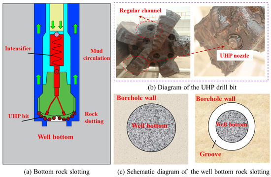
Figure 1.
Bottom rock slotting method.
The downhole intensifier is a crucial system for enhancing hydraulic energy at the bottom of the well and plays a key role in implementing stress relief methods. The development of the drilling technique utilizing high-pressure water jets has undergone three stages: full ground pressurized water jet, partial ground pressurized water jet, and downhole pressurized water jet by intensifier [9]. In 1970, Maurer and others increased the overall circulating drilling fluid pressure to 68–105 MPa using surface pressure boosting devices, effectively tripling the mechanical drilling speed [10,11]. This method demonstrated that utilizing ultra-high-pressure jet drilling is an effective approach for improving drilling speed. However, field experiments have revealed that while full ground pressurized technology can effectively enhance drilling speed, it places significant demands on the pressure-bearing capacity of the drilling fluid circulation system, including pumps and pipelines. In the mid-1980s, Flow Drill and Grace jointly developed a dual-pipe drilling system. By pressurizing a small portion of the fluid with mud pumps on the surface, the pressurized fluid entered the drill bit through a high-pressure jet channel, while the unpressurized fluid was discharged through a conventional flow channel at the water outlets of the bit. This partial pressurizing at the surface increased the lifespan of mud pumps and surface high-pressure pipelines. However, the overall construction process became more complex, making it challenging to implement in practice. In 1995, FlowDrill and GRI collaborated to produce the first prototype of the downhole intensifier [12]. By pressurizing approximately 7% of the circulating drilling fluid, the intensifier induced high-speed water jet impacts on the bottom rock, facilitating rock fragmentation and assisting in rock breaking through the drill bit. However, the limitations of the seal structure of the pressurizing chamber resulted in the maximum working time of the experimental prototype being 40.5 h, with the minimum working time being only around 1 h. As a result, the downhole intensifier was not suitable for field applications. Compared to fully pressurized methods on the surface or partially pressurized methods on the ground, underground pressure intensifiers streamline the pressurization system and alleviate operational difficulties [13]. Furthermore, the intensifier was positioned in close proximity to the drill bit within the drill string, thereby obviating the necessity for retrieval in the event of tool malfunction while also ensuring that the flow of drilling fluid within the drill string remains unaffected.
Researchers have designed and refined a range of downhole intensifiers building on the initial exploratory experiences of FlowDrill [14,15]. A UHP nozzle is mounted above the drill bit, and the intensifier produces an ultra-high-pressure water jet. As the drill string rotates, this jet is used to create a circular groove in the rock at the bottom of the wellbore, as shown in Figure 1b. These intensifiers can be categorized into two modes, active and passive, based on the source of their driven energy [16]. Active intensification relies on energy conversion mechanisms driven by the hydraulic energy of the drilling fluid, converting fluid energy into mechanical energy that powers the pressurizing mechanism [17,18,19]. Active intensifiers primarily consist of two types: those driven by screw motors and those utilizing jet propulsion [20,21]. The screw-type intensifier employs a screw motor that, through a switching mechanism, converts the rotational motion of the screw motor into the linear reciprocating motion of the plunger, achieving periodic pressure boosting of the drilling fluid [22]. The output pressure characteristics of this intensifier form a triangular waveform, generating instantaneous high-pressure jets. The jet-driven type intensifier employs hydraulic energy to generate jet flows, which create wall attachment effects, facilitating the reciprocating motion of the plunger [23,24,25]. The output jet frequency depends on the structural characteristics of the jetting elements. Passive pressure intensification relies on energy generated during the drilling process, converting it into driving energy for the intensifier, resulting in ultra-high-pressure jets [26]. A typical example of passive pressure intensification is using the vibration energy of the drill string. This method not only reduces the amplitude of the drill string vibrations but also pressurizes the fluid using vibrational energy, leading to the generation of instantaneous high-pressure jets [27]. The pressure output characteristics of the intensifier utilizing the axial drill string vibration energy depend on the frequency characteristics of the vibrations [28].
The traditional theories of water jet rock breaking mainly center around aiding the drill bit in rock fracturing and debris removal. The latest downhole acceleration technology, which uses a combination of UHP water jets and mechanical impact to enhance rock-breaking efficiency, has shown significant effects in deep hard rock formations. By using an intensifier to generate UHP water jets, a circular groove is formed on the rock target at the bottom of the well, which relieves the local stress of the rock at the bottom of the well, and reduces the difficulty of impact rock breaking, as shown in Figure 1c. During actual drilling operations, the rotational speed of the drill bit varies with the lithology of the formation, and the slotting characteristics of the bottom rock are influenced by the jet characteristics of the intensifier. The larger the range of rock slotting at the bottom, the greater the degree of stress release [29,30]. The output pressure characteristics of the current downhole intensifiers are limited by the structure of the directional control unit, resulting in transient high-pressure water jets that lead to low efficiency in rock slotting during the drilling process. As a large number of automated control devices, including rotary steering tools and downhole wireless measurement-while-drilling instruments, are applied in the deep and ultra-deep oil and gas drilling industry, the development of downhole power supplies and controllers under high-temperature conditions can provide new approaches for the design of intensifiers [31,32].
In order to improve the duration of the high-pressure water jet of the bottom hole and enhance the rock-slotting efficiency, this study proposes a novel intensifier controlled by an electromagnetic valve. Additionally, the development of a prototype intensifier and the establishment of a laboratory test platform were undertaken. This study conducted comprehensive experiments to analyze the output characteristics of the intensifier and investigate various factors that influence its performance with the objective of developing a novel technical solution for improving drilling performances, in particular in deep hard rocks.
2. Methodology
2.1. Method for Generating Bottom Hole UHP Water Jet
2.1.1. Components of the Structure
The intensifier controlled by an electromagnetic valve comprises the control system, pressurizing system, and diamond bit, as illustrated in Figure 2. The control system incorporates a battery, controller, and two-way three-position electromagnetic valve. The pressurizing system is structured with the pressurizing chamber, plunger, and one-way valve. With a dual-flow configuration, the drill bit accommodates both the conventional drilling fluid channel and an ultra-high-pressure channel. The conventional drilling fluid enters the bottom of the wellbore through the water hole of the drill bit, serving the purpose of rock cleaning and assisting in rock fracturing. Simultaneously, an ultra-high-pressure nozzle is installed on the drill bit, where the pressurized jet impacts the target surface of the subsurface rock. Rock slotting is formed with the rotation of the drill bit, thereby enhancing the drilling ability of the rock. The working process of the intensifier can be divided into two stages: the pressurizing process and resetting process.

Figure 2.
Structure diagram of the intensifier controlled by an electromagnetic valve.
2.1.2. Working Principle
The working intensifier is illustrated in Figure 3. During the pressurizing process, a portion of the drilling fluid flows into the conventional drilling fluid flow channel, contributing to the circulation of the bottom drilling fluid. This flow helps to maintain equilibrium in the bottom stress field, facilitates the removal of cuttings generated while drilling, and contributes to the cooling of the drill bit. Meanwhile, the remaining fluid enters the pressurizing chamber. At this stage, the spool of the electromagnetic valve is positioned at the far-right end, allowing the drilling fluid to flow into the front pressurizing chamber A of the intensifier through the internal flow channel of the electromagnetic valve. Due to the larger area of the left side of the plunger within chamber A, the fluid exerts a differential pressure force on both ends of the plunger, propelling it to move from the front chamber A to the rear chamber B. As the plunger moves, it compresses the fluid in the rear chamber B of the intensifier, generating high-pressure fluid. Consequently, check valve 1 opens, allowing the high-pressure jet to impact the wellbore rock through the nozzle. Simultaneously, on the left side of check valve 2, there exists a low-pressure area, while on the right side, a high-pressure area is maintained, resulting in the closure of check valve 2. The pressurizing process concludes when the plunger reaches the right end of the intensifier after moving from the left end.
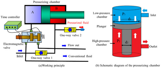
Figure 3.
Diagram of the working principle of the intensifier.
During the resetting process, the time controller emits a signal to regulate the electromagnetic valve, thereby switching the internal flow channel and closing the inlet flow channel. Part of the drilling fluid enters the conventional flow channel, participating in the drilling process and enabling the circulation of the drilling fluid. Simultaneously, another fraction of the fluid flows into the rear chamber B through check valve 2. In the course of this operation, the front chamber A establishes an atmospheric connection by means of the bypass flow channel in the electromagnetic valve, which results in the creation of a low-pressure state. As a consequence of the pressure differential, the plunger is compelled to move from the rear chamber B to the front chamber A. The resetting process is deemed complete when the plunger advances from the right end to the left end. Afterward, the controller sends a startup signal to the electromagnetic valve, thus restoring the pressurization status of the intensifier.
2.1.3. Force Analysis of the Plunger
During the operation of the intensifier, the plunger is subjected to the pressure differential force between the two ends of the liquid. This force compresses the fluid in the high-pressure chamber and generates a high-pressure water jet. The key parameters that impact the characteristics of the pulsating jet during the pressurization process are derived based on the dynamic characteristics of the plunger. The fluid medium for the lab test in this paper was clear water. In actual drilling operations, the limitations of the physicochemical properties of the drilling fluid can have a certain impact on the pressure intensification performance of the intensifier. In particular, the dynamic viscosity of the drilling fluid can cause the fluid to generate a significant viscous force during movement due to deformation under shear or tensile stress, which in turn generates greater internal frictional forces, consuming the energy of the fluid. To simplify the calculation of the dynamic model, the following assumptions are reasonably made: 1. The plunger and other components are treated as rigid bodies, disregarding the mechanical resistance caused by the deformation of the plunger and pressurizing chamber under high-pressure conditions. 2. The temperature, viscosity, and bulk modulus of the internal fluid remain constant throughout the pressurization process. 3. The pressurizing chamber and plunger exhibit good sealing performance, ensuring no leakage between the A chamber and chamber B during plunger operation.
During the initial phase of intensifier operation, the plunger undergoes accelerated motion due to the unequal effective areas in the front chamber A and rear chamber B of the pressurizing chamber. The dynamic equation that governs the motion of the plunger is as follows, assuming constant fluid properties:
In the equation, is the inlet pressure of the pressurizing chamber, is the output pressure of the intensifier, is the internal diameter of the pressurizing chamber, is the diameter of the plunger rod, is the mass of the plunger, is the displacement of the plunger during the acceleration motion, is the time taken for the acceleration motion of the plunger, and is the frictional force acting on the plunger.
After the intensifier reaches the steady-state operation, the plunger achieves a state of force equilibrium, resulting in the plunger moving at a constant velocity. The dynamic equation governing the motion of the plunger is as follows:
During the high-pressure jet output of the intensifier, the influence of frictional forces is minimal, and the ratio of output pressure to input pressure can be used as a metric to evaluate the pressurizing performance of the intensifier.
In the above formula, is the pressure ratio which is used to evaluate the pressurizing capacity of the intensifier. The output pressure of the intensifier is primarily influenced by the input pressure , the internal diameter of the pressurizing chamber , and the diameter of the plunger rod , and the effect of frictional forces is ignored.
2.2. Experimental Method for the Intensifier
The testing platform was established for assessing the output characteristics of the prototype intensifier, which operates based on the principle of the intensifier controlled by an electromagnetic valve. Pure water was chosen as the testing medium. Tests were conducted to evaluate the displacement and vibration characteristics of the plunger rod, as well as the output pressure characteristics. Moreover, the key factors influencing the output characteristics of the intensifier during operation were identified. The objective of these experiments is to establish a basis for optimizing the design of the intensifier.
2.2.1. Lab Test System
The testing system employs a self-developed downhole intensifier controlled by an electromagnetic valve pulse jet testing system, as depicted in Figure 4. This system encompasses the water supply system, the pressure acquisition and testing system, the vibration displacement testing system, and the intensifier prototype. The water supply system comprises a water tank, a high-pressure plunger pump, a pressure flow control system, and a safety valve, providing power and water replenishment for the intensifier. The pressure testing system consists of two digital sensors with a sampling frequency of 4 K and a range of 0 to 200 MPa. These sensors are, respectively, installed in the low-pressure chamber and high-pressure chamber of the intensifier. The displacement and vibration testing system includes a three-axis high-frequency vibration sensor, a laser displacement sensor, and a data acquisition computer. The visualization of the experiment facilitates the automatic collection of the output characteristics of the intensifier controlled by an electromagnetic valve.
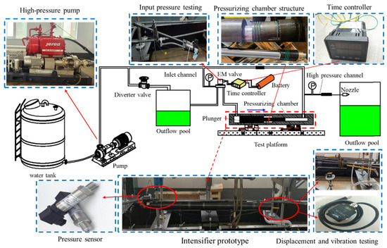
Figure 4.
Test system of the intensifier controlled by an electromagnetic valve.
2.2.2. Experimental Parameters
The test of the intensifier can be divided into three parts: start-up characteristic test (test 1), pressurizing capacity test (test 2), and output pressure waveform characteristic adjustment test (test 3). In these experiments, the displacement and vibration characteristics of the plunger rod during the operation of the intensifier were measured, along with the pressure and frequency of the output pulse jet from the high-pressure nozzle. The pressurizing chamber had a diameter of 80 mm, while the plunger rod had a diameter of 75 mm. The pressure ratio was approximately 1:8.25, and the plunger had a maximum stroke of 500 mm. Water was used as the input medium for these experiments. The specific details of the experimental parameters can be found in Table 1.

Table 1.
Experimental parameters.
2.2.3. Experimental Procedure
To ensure the accurate functioning of the testing system as depicted in Figure 4, it is imperative to meticulously install and connect the various components. Before proceeding with the connection of the pressure sensor, it is essential to perform a zero calibration, ensuring precise measurements are obtained under atmospheric pressure conditions. Additionally, careful attention should be given to sliding detection and zero adjustment for the displacement sensor, guaranteeing accurate and reliable displacement readings. Once these preliminary steps have been diligently completed, the water supply system should be opened, allowing for comprehensive leak detection procedures to be conducted. It is only after meticulous leak detection has been achieved that the final step can be undertaken: adjusting the pressure flow control system. The proper adjustment of this system will effectively facilitate the seamless operation of the intensifier, which is precisely controlled through the employment of an electromagnetic valve. By meticulously adhering to these sequentially organized steps, the integrity and accuracy of the testing system can be reliably ensured.
Firstly, the startup characteristic experiment for the intensifier needs to be conducted. The purpose of this experiment is to assess the frictional forces that the plunger has to overcome during the startup process. The input pump pressure should be gradually increased from 1 MPa until the intensifier functions normally. Next, the pressurizing capability test for the intensifier should be performed. To ensure that the plunger reaches the furthest position in the pressurizing chamber, the switching time of the electromagnetic valve should be set to 10 s. According to the specifications provided in Table 1, the inlet pressure of the intensifier should be increased progressively. The displacement and vibration characteristics of the plunger rod, as well as the pressure and frequency of the pulsed jet from the high-pressure nozzle, should be monitored. Lastly, the output pressure waveform modulation test for the intensifier should be carried out. A constant input pressure should be maintained and the switching time of the electromagnetic valve should be adjusted to evaluate the output pressure characteristics of the high-pressure nozzle. This test will provide insights into how the output pressure of the intensifier can be modulated and controlled; the flowchart of the testing process in this paper is shown in Figure 5.
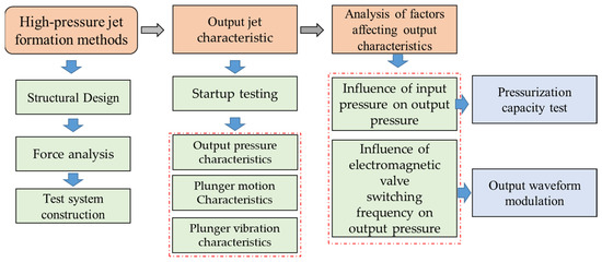
Figure 5.
Flowchart of the testing process.
3. Results and Discussion
3.1. Startup Characteristic Testing
The intensifier controlled by an electromagnetic valve is directly driven by the energy of the drilling fluid. The primary factor that significantly influences the performance of this intensifier is the pressure loss that occurs due to friction. To comprehensively assess its performance, a dedicated startup characteristic test was conducted. During this test, the pressure from the startup pump was gradually increased until the intensifier was fully operational, and the corresponding inlet pressure of the intensifier was meticulously recorded. In total, a series of five tests were systematically carried out to thoroughly evaluate the startup performance, as shown in Figure 6. From these tests, it was observed that the maximum recorded startup pressure for the intensifier reached 4.5 MPa, whereas the minimum startup pressure was determined to be 3.2 MPa. The calculation of the average startup pressure across the five tests yielded a value of 3.6 MPa. This is due to the fact that the plunger and pressurizing chamber require a high degree of precision during machining, and the intensifier must maintain proper coaxial alignment during installation. Excessive friction between the piston and the intensifier will not only affect the ability to increase pressure, but will also affect the life of the intensifier.
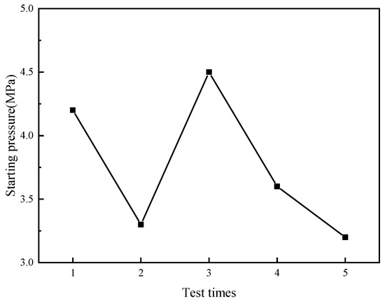
Figure 6.
Frictional force of the plunger.
3.2. Pressurizing Capability Testing
3.2.1. Output Jet Characteristic
The output pressure characteristics of the pressurized post-pulse water jet are of utmost importance in optimizing the efficiency of bottom rock slotting. By increasing the output pressure of the water jet, its rock-breaking capability is significantly enhanced, and the duration of the high-pressure water jet is prolonged as well, thereby leading to a substantively expanded range of slotting on the surface of the bottom rock. The output pressure characteristics of the downhole intensifier, controlled by an electromagnetic valve, exhibit pulsations over time. Within a single cycle, the pressure pulse comprises a mixed jet, formed by a segment of high-pressure jet output and a segment of low-pressure jet. This results in a pressure waveform resembling a square wave, as illustrated in Figure 7. The inlet pressure acts on the plunger end surface, propelling the plunger and pressurizing the fluid in chamber B of the intensifier by taking advantage of the area difference, thus generating high-pressure fluid. The outlet pressure of the intensifier rapidly increases from a low-pressure state to a high-pressure state, subsequently stabilizing as a super high-pressure water jet. At the moment of transitioning between the pressurizing process and resetting process, a significant transient high-pressure jet arises, providing impact force during the drilling process and creating pre-existing cracks on the rock face. Under the influence of a rotating drill bit, the stable high-pressure jet achieves continuous slotting on the bottom rock surface. With an input pressure of 14 MPa, the output pressure reaches approximately 108.4 MPa. Consequently, the pressure ratio of the intensifier is 7.74, and the duration of the high-pressure jet amounts to about 2.6 s. In practical drilling operations, drill bits typically rotate at speeds between 60 and 120 RPM, and the sustained duration of the high-pressure jet is sufficient to ensure continuous cutting on the bottom rock surface.
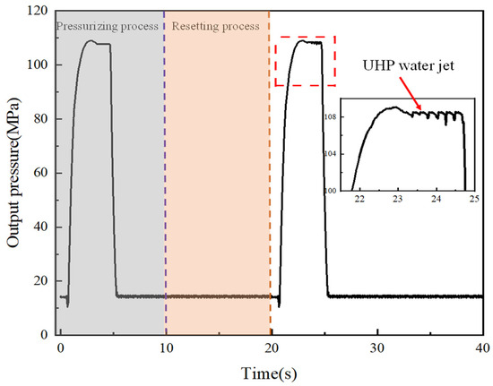
Figure 7.
Output jet feature of the intensifier.
The intensifiers utilizing screw motor and axial vibration energy are the two commonly employed types of intensifiers in petroleum drilling operations. The screw-type intensifier utilizes a screw motor, where the rotation is driven by the drilling fluid. The rotation of the cam at the lower end is also induced by this rotation, effectively transforming the rotational motion into the reciprocating linear motion of the plunger. The shape of the cams significantly affects the output pressure characteristics of the screw-type intensifier, often leading to the formation of triangular pressure waves, as depicted in Figure 8. On the other hand, the axial vibration energy intensifier utilizes a spring mechanism to absorb vibrational energy during drilling and converts it into the driving force for the plunger. The energy generated by vibrations in the drill string follows a sinusoidal pattern, which is reflected in the sinusoidal pressure output characteristic of the drill string damping intensifier, as shown in Figure 9. Both of these pressurizing methods briefly generate high-pressure jets, making it challenging to achieve continuous slotting on the surface of the rock bottom during the rotational drilling process. Compared to the output pressure characteristics displayed by the existing downhole intensifiers, the electromagnetic valve-controlled intensifier developed in this study excels in maintaining high-pressure jet flows for extended periods. This prolonged duration proves beneficial in facilitating stress release during rock slotting at the bottom, thereby enhancing drilling efficiency in challenging formations.
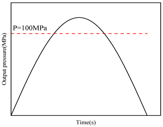
Figure 8.
Output jet feature of the intensifier utilizing axial vibration energy.
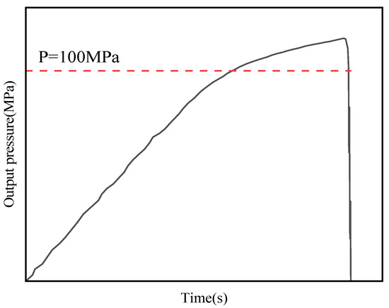
Figure 9.
Output jet feature of the intensifier utilizing a screw motor.
3.2.2. Plunger Motion Characteristics
Figure 10 illustrates the motion characteristics of the plunger during the operation of the intensifier. The working process of the intensifier can be divided into three phases: the pressurizing process, the static state, and the resetting process. During the pressurization process, the plunger undergoes a sequential pattern of acceleration, constant-speed motion, and deceleration. In this process, the plunger quickly reaches a relatively stable state of motion as a result of the pressure differential force. To ensure the full complete motion of the plunger during the pressurizing and resetting processes, the switch time of the work process was set to 10 s. Once the plunger reaches the extreme position of the pressurizing chamber, it remains stationary until the controller sends a signal to switch the working state of the intensifier. During the pressurizing process, the plunger is rapidly initiated under the influence of the liquid pressure differential. When the input pressure reaches 14 MPa, it takes approximately 1.8 s for the plunger to achieve a stable state of motion. In this stable motion state, the plunger moves at a speed of about 150 mm/s, and the pressurization process lasts for about 5.2 s. In the return process, the motion speed of the plunger in the stable state is about 130 mm/s, and the return time is approximately 5.8 s.
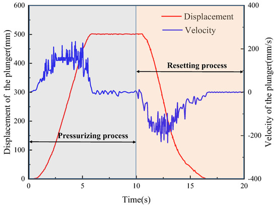
Figure 10.
Motion characteristics of the plunger.
To ensure the stable operation of the intensifier, a comprehensive study was undertaken to investigate the vibration characteristics of the plunger in both the horizontal and vertical directions during its operation. The experimental results, as depicted in Figure 11, demonstrate that the plunger experiences notable vibrations when the intensifier is abruptly initiated. The significant vibration in the initial stage is due to the fact that the switching process of the electromagnetic valve during the pressurizing process and the resetting process can generate large pressure fluctuations due to the water hammer effect. In the steady state, the vibration displacement during plunger movement is small, indicating the good sealing performance of the pressure intensifier chamber. Nevertheless, with the passage of time, the displacement caused by the vibrations gradually converges to an equilibrium state, resulting in a more consistent motion of the plunger. The obtained finding suggests that the pressurizing chamber is capable of maintaining a stable working condition, thereby ensuring consistent pressurizing effects. It is worth noting that the influence of gravity on the plunger leads to slightly reduced vibrations in the vertical direction compared to the horizontal direction. More precisely, when in a stable state, the plunger exhibits an average vibration displacement of approximately 70 μm horizontally and approximately 55 μm vertically. These significant experimental findings serve as vital references for further improving the design and enhancing the performance of the intensifier.
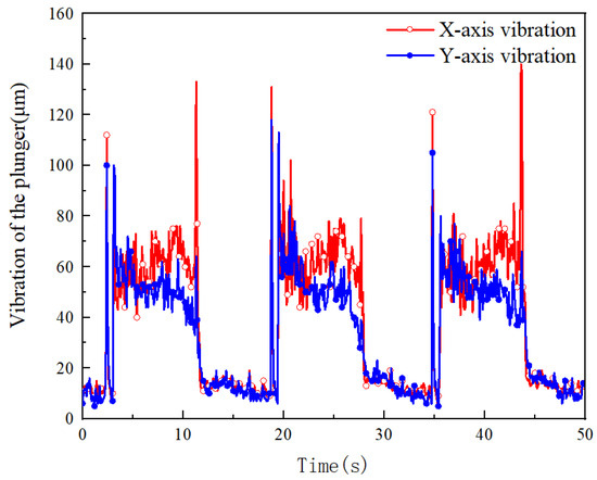
Figure 11.
Vibration characteristics of the plunger.
3.2.3. Influence of Input Pressure on Output Jet Characteristic
The pressurization capacity of the downhole intensifier is a crucial parameter for assessing its performance and determining its suitability for field applications. To investigate the effect of the input pressure on the output pressure of the intensifier, the time for both the pressurizing process and the resetting process was set to 10 s, ensuring that the plunger operates at full stroke. The jet pressure fluctuates periodically over time, encompassing stable pressure and impact pressure within a single pulse cycle. Figure 8 demonstrates the variations in the output pressure characteristics based on the input pressure. As the input pressure increases, the waveform of the output pressure remains square, while the peak pressure and duration of the high-pressure jet modify. During the pressurizing process, there is an increase in the thrust on the plunger end face in the front chamber A of the pressurizing chamber due to the rise in the input pressure. As the plunger reaches a state of force equilibrium, the peak pressure of the output pressure also increases during the steady stage, resulting in an increase in fluid pressure in the rear chamber B of the pressurizing chamber. The duration of the pressurizing and resetting process decreases, while the duration of the stable stage for the ultra-high-pressure jet reduces. When the plunger reaches the extreme position of the pressurizing chamber, it remains stationary, and the output pressure of the intensifier is equal to the input pressure, as shown in Figure 12.
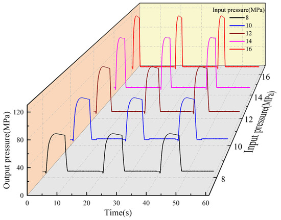
Figure 12.
Variations in output pressure waveform with input pressure changes.
During the process of increasing the input pressure from 8 MPa to 16 MPa, the average pressure during the steady stage increases from 63.5 MPa to 118.2 MPa. However, the duration of the ultra-high-pressure jet reduces from 4.5 s to 2.1 s. According to theoretical analysis, the pressure ratio of the intensifier is determined by the area ratio at both ends of the plunger. If the pressure ratio remains constant, the greater the inlet pressure, the greater the outlet pressure of the intensifier. When the input pressure is increased from 8 MPa to 16 MPa, the average pressure ratio of the intensifier is 1:7.8, which falls below the designed pressure ratio of 1:8.25. as shown in Figure 13. During the operation of the intensifier, the reciprocating motion of the plunger is achieved by switching between the inlet and outlet flow channels of the electromagnetic valve. During the switching process of the electromagnetic valve, there is a throttling effect due to the small orifice of the flow channel, resulting in some loss of inlet pressure. On the other hand, the starting characteristics of the intensifier and the vibration characteristics of the plunger also cause some pressure loss, which is the main reason why the actual output pressure is less than the theoretical output pressure. During the drilling process, the enhancement of the rock-slotting capabilities of the output jet can be achieved by augmenting the input pressure to the intensifier.
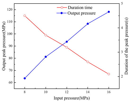
Figure 13.
Variations in output pressure feature with input pressure changes.
3.2.4. Influence of Input Pressure on Plunger Motion Characteristics
The driving energy of the intensifier, which is controlled by an electromagnetic valve, is derived from the energy of the drilling fluid. According to theoretical analysis, it is known that in the initial state, the intensifier undergoes accelerated motion under the effect of liquid pressure. When the liquid pressure at both ends of the plunger reaches equilibrium, the plunger moves at a constant speed. The higher the inlet pressure of the intensifier, the faster the plunger speed in the constant speed motion state, the shorter the time of the pressurizing process, and the shorter the duration of the UHP water jet. As illustrated in Figure 14, the running speed of the plunger during the pressurizing process is slightly higher than that during the resetting process. With an increase in input pressure from 8 MPa to 16 MPa, the running speed of the plunger during the pressurizing process rises from 0.05 m/s to 0.13 m/s, while the running speed during the resetting process increases from 0.03 m/s to 0.12 m/s. Consequently, the duration of the pressurizing process reduces from 0.05 s to 0.13 s, and the duration of the resetting process also decreases from 0.05 s to 0.13 s.
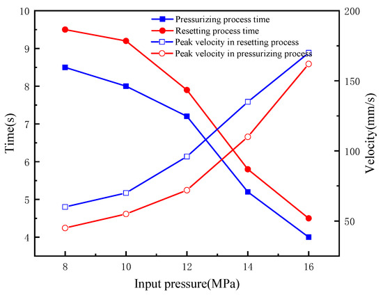
Figure 14.
Variations in plunger motion characteristics with input pressure changes.
In the course of operating the intensifier, the vibration displacement of the plunger can be utilized as an indicator to evaluate the adequacy of the system’s functionality. The output pressure exhibits a direct proportionality to the inlet pressure, whereby an increase in the inlet pressure corresponds to a higher output pressure. As the plunger achieves a state of steady motion, it results in an elevated pressure exerted on both ends, subsequently leading to intensified vibrations. The influence of gravity partially mitigates vibrations in the Y-direction, resulting in reduced Y-direction vibrations compared to the X-direction when the plunger is in a balanced state, as shown in Figure 15. For instance, at an input pressure of 16 MPa and an outlet pressure of 118.2 MPa, the average Y-direction vibration of the plunger in a stable state measures 47 μm, while the average X-direction vibration measures 77 μm. The experimental test results indicate that the intensifier exhibits minimal plunger vibration during high-pressure output, underscoring the stability and high reliability of plunger operation within the pressurizing mechanism.
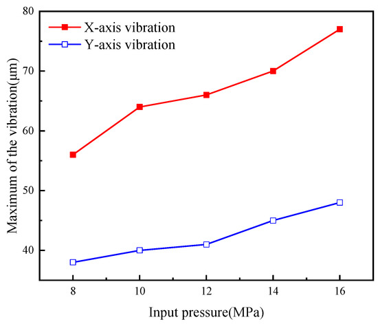
Figure 15.
Variations in plunger vibration characteristics with input pressure changes.
3.3. Output Waveform Modulation
In rotary drilling, it is necessary to achieve an adjustable frequency for the pressurizing jet flow in order to prevent repetitive impacts in the same location. This ensures that the working cycle of the intensifier aligns with an integer multiple of the drill bit rotation cycle, thereby facilitating the achievement of continuous slotting. It follows from Section 3.2.1 that if the inlet pressure is set at 14 MPa, the ram will reach the extreme position of the pressure chamber in 4.7 s during the pressurizing process and in 5.6 s during the resetting process. Therefore, the initial switching time of the electromagnetic valve was set to 6 s, and then the output waveform modulation test was performed.
Maintaining a constant input pressure allows for the examination of how the switching frequency of the electromagnetic valve impacts the characteristics of the output pressure. This investigation involves varying the switching time of the controller. The input pressure remains unchanged throughout the adjustments made to the switching frequency of the electromagnetic valve. When the plunger attains a state of equilibrium, the pressure exerted on both ends of the intensifier becomes equal, resulting in a consistent peak output pressure. As the switching frequency of the electromagnetic valve increases, the reciprocating speed of the plunger accelerates, leading to a higher output jet frequency from the intensifier and a shorter duration of the peak phase of the high-pressure jet. When the switching time of the electromagnetic valve is reduced from 6 to 0.5 s, the output pressure waveform transitions from a square wave to a triangular wave, transforming the stable ultra-high-pressure pulsed jet into a transient high-pressure pulsed jet, as illustrated in Figure 16.
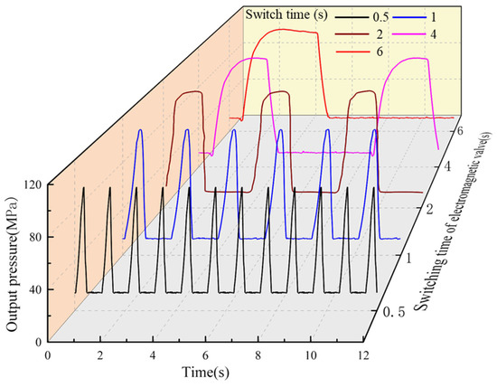
Figure 16.
Variations in output pressure waveform with switching frequency changes.
Upon decreasing the switching interval of the electromagnetic valve from 6 s to 1 s, the peak output pressure of the high-pressure jet from the intensifier is maintained, albeit with a shortened duration of the peak jet pressure phase. With a 1 s switching interval for the electromagnetic valve, the intensifier generates a transient pulsed jet, corresponding to a pressure output frequency of 0.5 Hz, as depicted in Figure 17. During the operation of the intensifier, the inlet pressure is maintained constant and the force on the plunger remains unchanged throughout its movement; therefore, the output pressure of the intensifier is essentially constant. However, during the pressurization process, it takes 0.7 s for the intensifier to transition from the start-up state to a stable output state. When the switching interval is 0.5 s, the intensifier is unable to achieve the peak pressure before the valve switches, resulting in a maximum output pressure of 106.7 MPa. When the switching time of the electromagnetic valve is greater than 1 s, the intensifier can reach its peak output pressure, which is approximately 118.4 MPa. The longer the switching time of the electromagnetic valve, the longer the duration of the peak pressure.
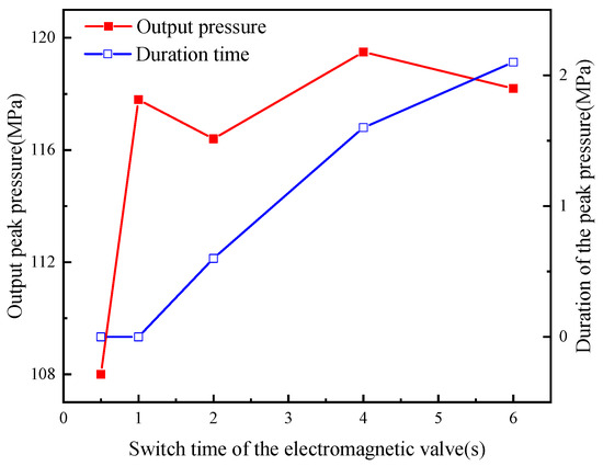
Figure 17.
Variations in output pressure feature with switching frequency changes.
4. Conclusions
Harnessing the power of UHP water jets to excavate rock at the bottom of the well can effectively reduce local stress concentrations and significantly improve the fracturing efficiency of deep-seated hard rock. A novel downhole intensifier has been developed to overcome the problem of low slotting efficiency due to the short duration of peak output pressure in the current intensifiers. Extensive experimental testing has been conducted to analyze the output pressure characteristics, pressurization capacity, and waveform modulation capabilities of this new intensifier. The key findings from these studies are outlined below:
- The output pressure characteristic of the intensifier controlled by an electromagnetic valve is a mixture of high- and low-pressure segments, with the output waveform being a square wave. The duration of the high-pressure segment is longer than that of conventional intensifiers. In actual rotary drilling operations, it is easier to form annular slots on the surface of the rock at the bottom of the hole.
- The pressure ratio is determined by the structural parameters of the intensifier. When the pressure ratio is constant, an increase in the input pressure will correspondingly increase the peak output pressure, increasing the rock-breaking capacity of the UHP water jet; by adjusting the switching frequency of the electromagnetic valve, the duration of the UHP water jet can be regulated. In rotary drilling, this can be matched with the rotation speed of the drill bit, further improving the overall efficiency of water jet rock slotting.
- In this study, a novel prototype downhole intensifier was developed that can achieve an output pressure of 118.2 MPa at an input pressure of 16 MPa with the UHP water jet lasting approximately 2.1 s. In actual drilling operations, the downhole environment is complex, with high temperatures, high pressures, and high-frequency vibrations challenging the intensifier. Further work is needed to optimize the structure of the intensifier to provide new equipment to enhance drilling efficiency in deep hard rock formations.
Author Contributions
Conceptualization, Y.H. and H.L.; methodology, W.N.; investigation, J.N.; resources, Y.H. and M.W.; data curation, Y.H.; writing—original draft preparation, H.L. and H.W.; writing—review and editing, M.W.; funding acquisition, H.L. All authors have read and agreed to the published version of the manuscript.
Funding
This research was supported by the National Key Research and Development Program of China (2021YFE0111400).
Data Availability Statement
The raw data supporting the conclusions of this article will be made available by the authors upon request.
Conflicts of Interest
Author Minsheng Wang is employed by the Sinopec Research Institute of Petroleum Engineering Co., Ltd. The remaining authors declare that the research was conducted in the absence of any commercial or financial relationships that could be construed as a potential conflict of interest.
References
- Zhang, J.; Zhang, B.; Liu, B.; Li, B. Investigation on the influence of the frequency of pulsed water jet on the rock-breaking effect. Powder Technol. 2024, 431, 119054. [Google Scholar] [CrossRef]
- Hu, H.; Guan, Z.; Zhang, B.; Xu, Y.; Liu, Y.; Wang, B. Structure design of weight-on-bit self-adjusting PDC bit based on stress field analysis and experiment evaluation. J. Pet. Sci. Eng. 2021, 196, 107692. [Google Scholar] [CrossRef]
- Tian, J.; Fan, C.; Zhang, T.; Zhou, Y. Rock breaking mechanism in percussive drilling with the effect of high-frequency torsional vibration. Energy Sources Part A Recovery Util. Environ. Eff. 2019, 44, 2520–2534. [Google Scholar] [CrossRef]
- Cheng, Z.; Sheng, M.; Li, S.; Huang, Z.; Wu, X.; Zhu, Z.; Yang, J. Imaging the formation process of cuttings: Characteristics of cuttings and mechanical specific energy in single PDC cutter tests. J. Pet. Sci. Eng. 2018, 171, 854–862. [Google Scholar] [CrossRef]
- Che, D.; Zhu, W.; Ehmann, K. Chipping and crushing mechanisms in orthogonal rock cutting. Int. J. Mech. Sci. 2016, 119, 224–236. [Google Scholar] [CrossRef]
- Li, Y.; Peng, J.; Zhang, P.; Huang, C. Hard Rock Fragmentation in Percussion Drilling Considering Confining Pressure: Insights from an Experimental Study. Int. J. Rock Mech. Min. Sci. 2021, 148, 104961. [Google Scholar] [CrossRef]
- Liu, S.; Chang, H.; Li, H.; Cheng, G. Numerical and experimental investigation of the impact fragmentation of Bluestone using multi-type bits. Int. J. Mech. Sci. 2017, 91, 18–28. [Google Scholar] [CrossRef]
- Liao, H.; Guan, Z.; Shi, Y.; Liu, Y. Field tests and applicability of downhole pressurized jet assisted drilling techniques. Int. J. Rock Mech. Min. Sci. 2015, 75, 140–146. [Google Scholar] [CrossRef]
- Kolle, J.; Otta, R.; Stang, D. Laboratory and testing of an ultra-high pressure, jet-assisted drilling system. In Proceedings of the SPE/IADC Drilling Conference, Amsterdam, The Netherlands, 11–14 March 1991; p. SPE-22000-MS. [Google Scholar] [CrossRef]
- Veenhuizen, S.; Stang, D.; Kelley, D.; Duda, J.; Aslakson, J. Development and testing of downhole pump for high-pressure jet-assist drilling. In Proceedings of the SPE Annual Technical Conference and Exhibition, San Antonio, TX, USA, 5–8 October 1997; p. SPE-38581-MS. [Google Scholar] [CrossRef]
- Maurer, W.; Weiss, C. Tapered high-pressure water-jet nozzles: Experimental performance analysis and potential for cutting underground rock. J. Hydraul. Res. 2005, 43, 525–532. [Google Scholar]
- Tutluoglu, L.; Hood, M.; Barton, C. An investigation of the mechanisms of water jet assistance on the rock cutting process. In Proceedings of the 24th U.S. Symposium on Rock Mechanics (USRMS), College Station, TX, USA, 20–23 June 1983; p. ARMA-83-0743. [Google Scholar]
- Veenhuizen, S.; Hanlon, T.; Kelley, D.; Duda, J.; Aslakson, J. Ultra-High Pressure Down Hole Pump for Jet-Assisted Drilling. In Proceedings of the IADC/SPE Drilling Conference, New Orleans, LA, USA, 12–15 March 1996; p. SPE-35111-MS. [Google Scholar] [CrossRef]
- Al-Safran, E.; Aql, A.; Nguyen, T. Analysis and prediction of fluid flow behavior in progressing cavity pumps. J. Fluids Eng. 2017, 139, 121102. [Google Scholar] [CrossRef]
- Nguyen, K.; Nguyen, T.; Al-Safran, E. Modeling the performance of progressive cavity pump under downhole conditions. J. Pet. Sci. Eng. 2021, 198, 108121. [Google Scholar] [CrossRef]
- Liao, H.; He, Y.; Wang, H.; Wang, M.; Wei, J.; Niu, J. Experimental and numerical investigation of the novel downhole intensifier controlled by electromagnetic valve. Geoenergy Sci. Eng. 2024, 233, 212472. [Google Scholar] [CrossRef]
- Latra, B.; Cherifa, A. Influence of the position of an Internal Heat Exchanger on the performance of a Dual-Evaporator Ejector Refrigeration System. J. Energy Resour. Technol. 2024, JERT-24-1393, 1–40. [Google Scholar] [CrossRef]
- Guan, Z.; Zhang, B.; Zhang, H.; Zhang, B. Development and Application of the Downhole Drilling String Shock-Absorption and Hydraulic Supercharging Device. Shock. Vib. 2016, 1, 2041671. [Google Scholar] [CrossRef]
- Dong, G.; Chen, P. 3D Numerical Simulation and Experiment Validation of Dynamic Damage Characteristics of Anisotropic Shale for Percussive-Rotary Drilling with a Full-Scale PDC Bit. Energies 2018, 11, 1326. [Google Scholar] [CrossRef]
- Jiang, H.; Cai, Z.; Wang, O.; Meng, D. Experimental and numerical investigation of hard rock breakage by indenter impact. Shock Vib. 2020, 2020, 2747830. [Google Scholar] [CrossRef]
- Zhao, J.; Zhang, G.; Xu, Y.; Lin, A.; Zhao, J.; Yang, D. Enhancing rate of penetration in a tight formation with a high-pressure water jet (HPWJ) via a downhole pressurized drilling tool. J. Pet. Sci. Eng. 2018, 174, 1194–1207. [Google Scholar] [CrossRef]
- Zhang, H.; Guan, Z.; Liu, Y.; Liang, D.; Xu, Y. A novel tool to improve the rate of penetration by transferring drilling string vibration energy to hydraulic energy. J. Pet. Sci. Eng. 2016, 146, 318–325. [Google Scholar] [CrossRef]
- Liu, S.; Ji, H.; Han, D.; Guo, C. Experimental Investigation and Application on The Cutting Performance of Cutting Head for Rock Cutting Assisted with Multi-water Jets. Int. J. Adv. Manuf. Technol. 2018, 94, 2715–2718. [Google Scholar] [CrossRef]
- Xu, Y.; Zhou, C.; Liu, Y.; Zhao, H. Principle and design of screw downhole supercharger. Drill. Prod. Technol. 2011, 34, 71–74. [Google Scholar]
- Yang, X.; Li, X.; Lu, Y. Wear Characteristics of the Cemented Carbide Blades in Drilling Limestone with Water Jet. Int. J. Refract. Met. Hard Mater. 2011, 29, 320–325. [Google Scholar] [CrossRef]
- Liu, W.; Zhu, X.; Jing, J. The analysis of ductile-brittle failure mode transition in rock cutting. J. Pet. Sci. Eng. 2018, 163, 311–319. [Google Scholar] [CrossRef]
- Xue, L.; Li, B.; Wang, Z.; Li, B. Ultra high-pressure-jet-assisted drilling technique: Theory and experiment. J. Can. Pet. Technol. 2012, 51, 276–282. [Google Scholar] [CrossRef]
- Xuan, L.; Guan, Z.; Hu, H.; Li, J.; Zhang, B. The Principle and Application of a Novel Rotary Percussion Drilling Tool Derived by Positive Displacement Motor. In Proceedings of the IADC/SPE Asia Pacific Drilling Technology Conference, Singapore, 22–24 August 2016; OnePetro: Richardson, TX, USA, 2016; pp. 1–10. [Google Scholar] [CrossRef]
- Huang, K.; Feng, Y.; Zhou, C.; Chen, L.; Yang, Y.; Wang, X.; Fu, C.; Zhang, C. Analysis of bit-balling failure and hydraulic structure optimization design of annular-grooved PDC bits. Geoenergy Sci. Eng. 2024, 241, 213134. [Google Scholar] [CrossRef]
- Arevalo, Y.; Fernandes, A. Quantification of drillstring-integrity-failure risk using real-time vibration measurements. SPE Drill. Complet. 2012, 27, 216–222. [Google Scholar] [CrossRef]
- Khorzoughi, M.; Hall, R.; Apel, D. Rock fracture density characterization using measurement while drilling (MWD) techniques. Int. J. Min. Sci. Technol. 2018, 28, 859–864. [Google Scholar] [CrossRef]
- Berro, M.; Reich, M. Laboratory investigations of a hybrid mud pulse telemetry (HMPT)-A new approach for speeding up the transmitting of MWD/LWD data in deep boreholes. J. Pet. Sci. Eng. 2019, 183, 106374. [Google Scholar] [CrossRef]
Disclaimer/Publisher’s Note: The statements, opinions and data contained in all publications are solely those of the individual author(s) and contributor(s) and not of MDPI and/or the editor(s). MDPI and/or the editor(s) disclaim responsibility for any injury to people or property resulting from any ideas, methods, instructions or products referred to in the content. |
© 2024 by the authors. Licensee MDPI, Basel, Switzerland. This article is an open access article distributed under the terms and conditions of the Creative Commons Attribution (CC BY) license (https://creativecommons.org/licenses/by/4.0/).