Article

Fuzzy Fault Tree Analysis and Safety Countermeasures for Coal Mine Ground Gas Transportation System

1
IoT Perception Mine Research Center, China University of Mining & Technology, Xuzhou 221116, China
2
School of Safety Engineering, China University of Mining and Technology, Xuzhou 221116, China
3
School of Emergency Management and Safety Engineering, North China University of Science and Technology, Tangshan 063210, China
*
Authors to whom correspondence should be addressed.
Processes 2024, 12(2), 344; https://doi.org/10.3390/pr12020344
Submission received: 9 January 2024 / Revised: 29 January 2024 / Accepted: 2 February 2024 / Published: 6 February 2024
(This article belongs to the Section Energy Systems)

Abstract

:
The coal mine ground gas transportation system is widely used for gas transportation and mixing preheating in the gas storage and oxidation utilization system. However, gas or coal dust explosions may occur, which could result in heavy casualties and significant economic losses. To prevent accidents in the gas transportation system, the present study takes the gas transportation system of Shanxi Yiyang Energy Company as an example to identify the composition and hazardous factors of the gas transportation system. Fault tree analysis (FTA) models were established with pipeline gas and coal dust explosions as the top events, and the importance of each basic event was quantitatively analyzed using the fuzzy fault tree analysis (FFTA) method. The results show that gas and coal dust explosion accidents are mostly caused by the combination of high-temperature ignition sources and explosive materials. The uneven mixing gas and the ventilation carrying a large amount of coal dust are the fundamental causes of coal mining accidents. Consequently, based on the general pipeline safety measures, gas indirect preheating, ventilation air methane in dust removal, and gas intelligent mixing and regulation were proposed to enhance the safety of the gas transportation system.

1. Introduction

The regenerative oxidation of coal mine gas is utilized to effectively reduce the emission of low-concentration coal mine methane [1] in coal mine gas power generation and waste heat heating [2,3]. The system is mainly composed of a gas transportation system, an RTO system, a power generation system, and a waste heat utilization system [4]. The gas transportation system is responsible for providing gas sources and blending gases to available concentrations, and it is an important subsystem of the regenerative oxidation utilization system [5,6]. However, due to the explosive hazard of low-concentration gas inside the pipelines and the complexity of the external environment, accidents are prone to occur during gas transportation [7]. Therefore, it is of great significance to analyze the safety of the gas transportation system and propose measures.
In recent years, with the promotion and popularization of coalbed methane extraction and gas surface utilization, the frequency of accidents during the transportation of gas has gradually increased [8]. On 26 October 2015, a gas extraction pipeline explosion occurred in the Wuyang Coal Mine in Shanxi Province, leading to the death of one miner [9]. On 31 July 2014, a gas pipeline explosion in Kaohsiung was attributed to acetylene leakage, resulting in 26 deaths and 280 injuries [10]. On 4 January 2010, at Nanping Steel Gas Plant in Wu’an City, Hebei Province, a gas pipeline leakage led to 21 casualties and 9 injuries [11]. On 20 January 2006, a natural gas pipeline explosion occurred in Renshou County, Sichuan Province, causing 243 deaths and 4 severe injuries; 30 people were slightly injured, and 1837 were evacuated in the surrounding accident area [12]. Explosion accidents in gas transportation systems have resulted in significant casualties and property losses.
Gas pipeline explosion accidents are characterized by destructive power, wide impact range, and serious consequences [13], and the non-metallic pipelines in mine gas extraction systems have been extensively damaged. Furthermore, the large amount of toxic and harmful gases produced by the explosion and pipe combustion poses a great threat to workers’ health and safety [14]. Studies on accident mechanisms and prevention and control technology have been conducted to prevent gas pipeline transportation accidents. Cai et al. [15] established the leakage and diffusion model for gas extraction pipelines to analyze the characteristics of pipeline leakage and diffusion accidents. Numerical simulation was applied in investigating the propagation laws of flames and pressure waves during gas pipeline explosions by Huang et al. [16], providing theoretical guidance for suppressing gas explosions. Zhu et al. [17] studied the flow field characteristics of gas explosions in complex pipelines and designed targeted explosion-proof devices. The pipeline leakage diagnosis method was proposed by Zhou et al. [18] to detect pipeline leakage accurately and promptly. The main types and causes of accidents in gas pipelines have been studied through statistical analyses of accidents. Lam et al. [19] conducted a statistical analysis of onshore natural gas pipeline accidents in the United States from 2002 to 2013 and revealed that pipeline damage was induced by pipeline material corrosion and external damage. Xiao et al. [20] investigated the relationships among the basic events of pipeline accidents and their consequences through US PHMSA. Fault tree analysis has been used to analyze gas pipeline accidents in previous studies as well, such as Dong et al. [21], who constructed a fault tree for pipeline leakage and rupture in oil and gas transportation to evaluate the failure probability of top events and the importance of basic events.
The explosion accidents in gas transportation pipelines of gas regenerative thermal oxidizers, especially accompanied by coal dust explosions [22], have not been investigated in previous studies. During the gas extraction process, a large amount of coal dust accumulates in the pipeline. When a gas explosion occurs, the deposited coal dust is suspended again by the shock wave in the pipeline, reaching the explosive concentration and being ignited by a gas flame; then, a coupled explosion of gas and coal dust occurs [23]. Gas–dust coupled explosions involve complex physical–chemical reactions, leading to more serious consequences. Although advances have been made in insolating and suppressing explosion and control techniques in recent decades, accidents in coal mines and gas transportation systems still occur infrequently. In order to ensure the safety of personnel and facilities around the pipeline, it is necessary to prevent gas explosions and coal dust explosion accidents in a gas transportation system. Therefore, it is indispensable to analyze gas and dust explosions in pipelines and to implement preventive measures.
Commonly used system security analysis methods include hazard and operability (HAZOP), failure mode and effect analysis (FEMA), event tree analysis (ETA), fault tree analysis (FTA), Bayesian network (BN), etc. HAZOP is a method of hazard identification that starts by analyzing the functional structure of a system to identify potential sources of hazard by analyzing various functional abnormalities and potential hazardous consequences [24]. The subsystems and each process are systematically analyzed via FMEA to find out all potential failure modes and analyze their possible consequences [25]. ETA is a method of identifying hazard sources by inferring possible consequences from the initial event [26]. The system faults are categorized as mutually independent and fully inclusive via BN, and then a Bayesian network model is constructed for each fault category [27]. The above analysis method has high accuracy, but it cannot quickly analyze the root cause and importance of the gas and coal dust explosion accident. FTA starts by analyzing the specific accident or fault, proceeding to analyze each layer until finding the basic causes of the accident that meet the research requirements [28]. For the cause-and-effect relationship of accidents, fault tree analysis gives intuitive, clear, and logical results, and allows for both qualitative and quantitative analysis [29,30,31]. This method has been extensively applied in industries such as aerospace, nuclear energy, petroleum, chemical engineering, and mining [32,33,34]. In order to address the challenge of obtaining probabilities for basic events, Tanaka created a fuzzy fault tree analysis method which replaces precise probability values with fuzzy probability and has been shown to be highly effective for fault trees of top and bottom event probabilities [35,36].
The gas oxidation utilization system of the Shanxi Yiyang Energy Company serves as an example in the current investigation. First, the composition of the gas transportation system and the safety precaution measures are introduced. Then, for a gas and coal dust explosion accident in the gas transmission pipeline, a fault tree was compiled, and a fuzzy fault tree analysis was performed. The expert scoring method and imprecise probability transformation are used to calculate the fuzzy number of each basic event, and the fuzzy number method is applied to estimate the probability of gas and coal dust explosion accidents. Finally, based on the analysis, novel risk prevention measures are proposed to prevent gas and coal dust explosions in the transportation system.

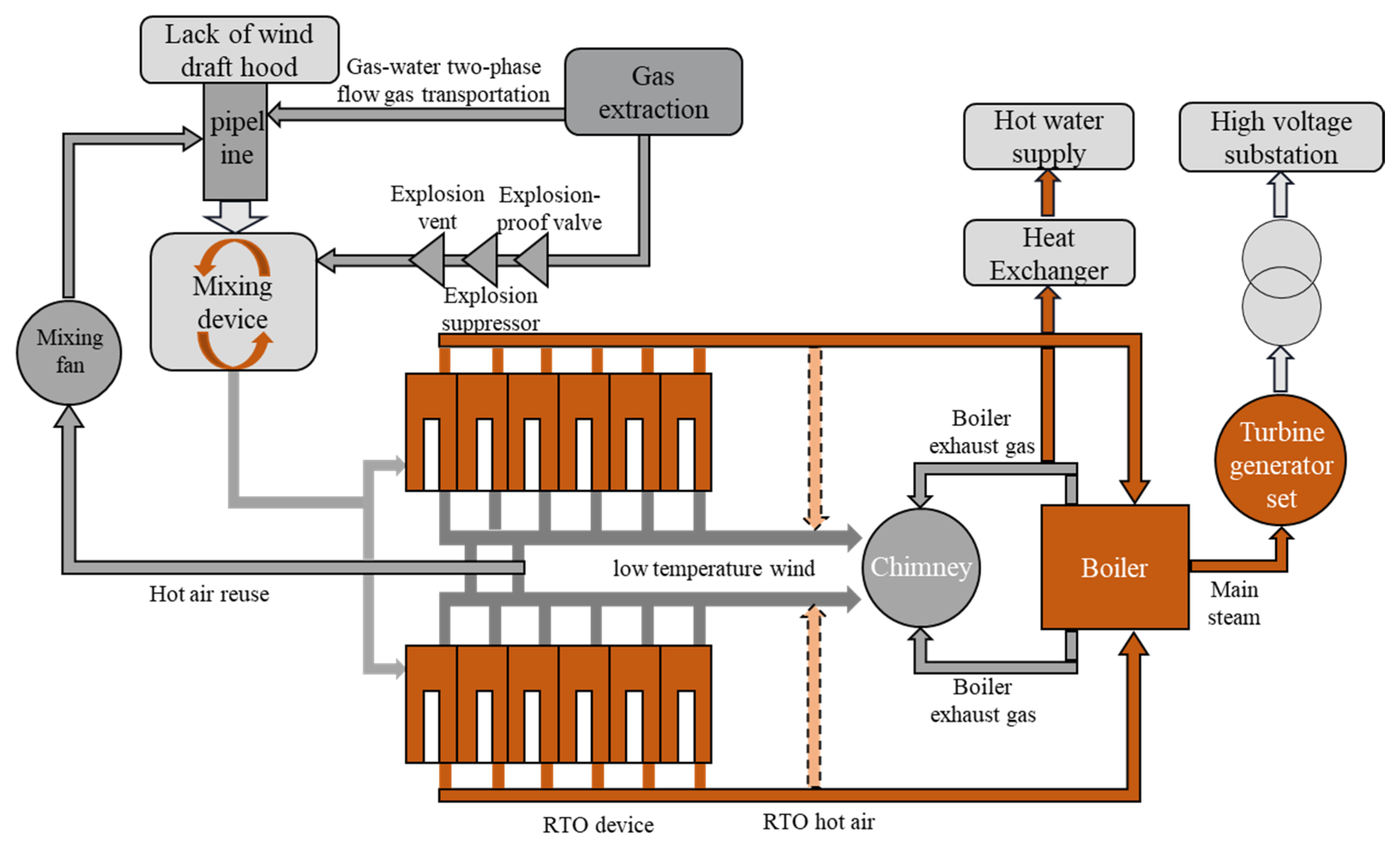
2. Gas Transportation System and Safety Incidents

The gas transportation system of the Shanxi Yiyang Energy Company’s coal mine primarily serves the coal mine gas oxidation power generation project, including an exhaust ventilation system and a gas transportation system. The design is carried out in accordance with the “Coal Mine Safety Regulations”, “Technical Specifications for Power Generation of Coal Mine Gas Regenerative Oxidation Devices”, “Design Specifications for Coal Mine Low Concentration Gas Pipeline Transmission Safety Guarantee System”, and other specifications. The coal mine ventilation air methane from the central shaft and the gas extraction from the gas pumping station are transported and mixed, respectively, adjusting the gas concentration to 1.2%. The gas is then introduced into the heat storage oxidation unit to produce high-temperature flue gas for power generation. The project is designed to process 9.4 billion cubic meters of gas annually, achieving an annual power generation of 200 million kilowatt-hours and reducing greenhouse gas emissions by 1.4 million tons of CO2 equivalent per year [37]. The gas oxidation power generation system is mainly composed of the exhaust ventilation system, the gas transportation and mixing system, the regenerative oxidation system, the power generation system, and the hot air recycling system. The process flow diagram is shown in Figure 1.

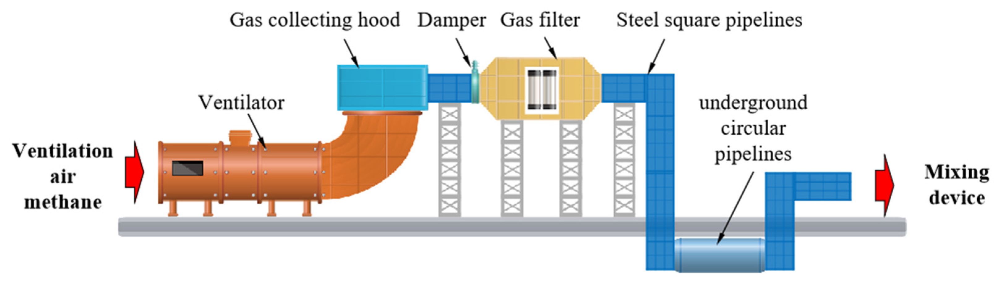
2.1. Exhaust Ventilation System

The exhaust ventilation system is mainly used to transport the ventilation air methane from the main ventilator of the mine to the mixing device, as shown in Figure 2. The system mainly consists of the ventilator, gas collecting hood, pipelines, dampers, gas filters, and distribution pipes. There are two ventilators in the ventilator room, one in operation and one on standby, with a total ventilation air methane volume of 1,580,000 Nm3/h. The ventilation air methane from the ventilator shaft is collected through the gas collecting hood, passes through the damper, gas filter, and ventilation connection pipe before entering the 5.5 × 5.5 m steel ventilation air methane pipe for surface transmission, and then is transmitted underground through the 6.0 m-diameter corrugated steel pipe to the plant area. Furthermore, the gas is divided into 3 DN3500 mm circular pipelines connected to the mixing device and then collected into the 5.5 × 5.5 m exhaust air pipe and finally divided into two 4 × 4 m pipelines to the oxide power generation equipment. The system structure and layout are mainly based on functional needs and site conditions. Although the task of conveying the ventilated air can be completed, the coal dust control issue in the mine-ventilated air has not been taken seriously, which may cause the coal dust carried by the ventilated air to enter the downstream pipelines and be deposited.

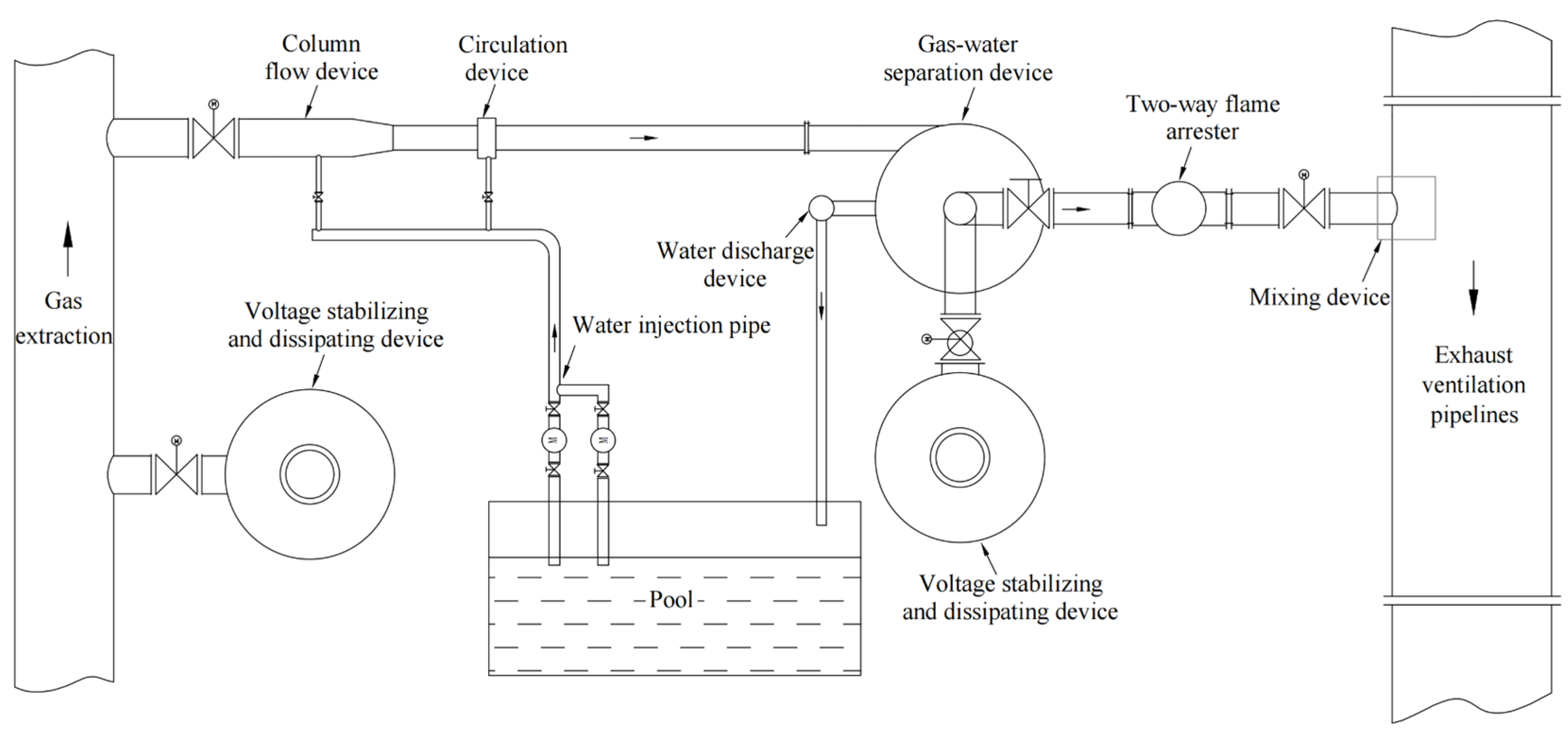
2.2. Gas Transportation and Mixing System

The gas transportation and mixing system comprises the gas–water two-phase flow gas transportation system, the dry explosion-proof gas transportation system, and the mixing system. Two transportation methods are, respectively, used for the transportation and mixing of gas extraction at the Baocun Gas Pumping Station and the Gaohe Gas Pumping Station.

2.2.1. Gas–Water Two-Phase Flow Gas Transportation System

The Baocun Gas Transportation Project was implemented to provide ample gas resources for gas utilization. The gas extraction at the Baocun Pumping Station is transported to the location of the Gaohe project using a water ring vacuum pump. The gas from Baocun Pumping Station is pumped to a 6.0 m-diameter ventilation-underground pipeline by gas-water two-phase flow, then further mixed with the ventilation gas. The gas–water two-phase flow safety transportation system [38], as shown in Figure 3, is mainly used for positive-pressure pipeline transportation of low-concentration gas. The system utilizes water flow to move along the inner wall of the transportation pipeline, with the gas flow moving within the annular water flow cavity. Additionally, the intermittent plunger water cluster is generated along the flow direction, and the gas flow is divided into segments to achieve safe transportation of low-concentration gas. The low-concentration gas undergoes gas–liquid separation in an explosion-proof and fire-resistant gas–liquid separator before entering the utilization facility. The separated water flows back for recycling, while the dehydrated gas source can be directly supplied to gas generator units for comprehensive utilization.
Three outlet pipes processed into the DN400 mixing pipe with a 45° cut angle are employed in gas extraction at Baocun, and the pipes are inserted into the exhaust air transport pipeline for mixing. The mixing pipes are uniformly arranged around the center of the exhaust air transport pipeline and have 10° axial and radial clockwise offsets, allowing the gas to enter in a spiral shape to reach the maximum gas disturbance. When high-pressure gas is introduced into the low-pressure exhaust air transport pipeline, the turbulent exhaust air immediately disperses the gas, enabling the rapid diffusion of low-concentration gas in the air for an optimal mixing effect.

2.2.2. Dry Explosion-Proof and Explosion-Venting Gas Transportation System

A dry explosion-proof and explosion-venting gas transportation system [39] is employed to ensure the safe transportation of gas extraction in the Gaohe Gas Pumping Station, as illustrated in Figure 4. The gas extraction sequentially passes through a butterfly valve, an automatic powder fire suppression device, and a water-sealed fire and explosion-venting device before entering the gas-mixing device. In the event of backfire, the flame and pressure sensors are installed to control the powder explosion suppression device; moreover, the water sealing of the fire barrier and explosion-venting device safely takes effect. The system can limit gas explosions within a finite range, effectively preventing the occurrence and expansion of accidents.
The dynamic continuous mixing device is used to mix the gas extraction from the Gaohe Gas Pumping Station with the ventilation air. The inner and outer directions are inverse in the spiral medium channel structure, and two gases are introduced through the inner and outer pines and are released and mixed at the two outlets of the spiral medium channel structure. The gas concentration sensor is installed to monitor the mixed methane, thereby determining the mixing accuracy of the dynamic continuous mixing device. When the mixed gas concentration exceeds 1.2%, the regulating valve installed on the gas inlet is adjusted by the gas monitoring system to control the amount of gas entering the mixing device, ensuring that the concentration of the mixed ventilation air methane remains below 1.2%. Three mixing pipelines are employed in the ventilation air methane mixing system, each with two mixing devices installed in series.

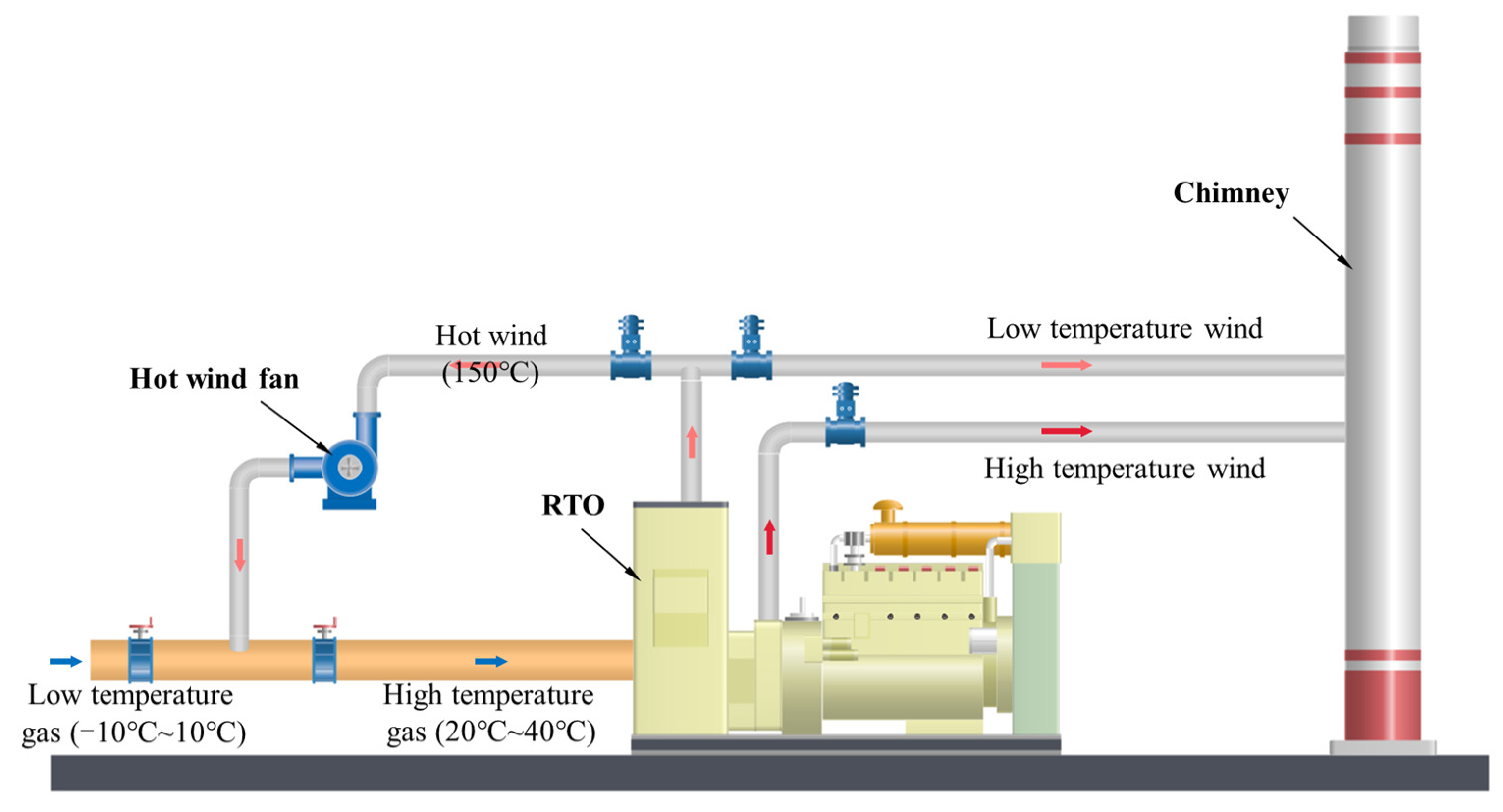
2.3. Gas Regenerative Oxidation Power Generation System

The gas regenerative oxidation power generation system is equipped with 12 RTO (regenerative thermal oxidizer) units. Due to the strong adaptability, the RTO units can operate continuously when the methane concentration in the inlet air is not less than 0.27%. Each RTO unit, containing two Integrated heat exchange beds with internal insulation, is filled with a sufficient medium with low-pressure drop and uniform heat transfer characteristics. Moreover, the entrainment residuum decreases to a minimum, and the efficiency of methane decomposition enhances. The RTO system is equipped with a state-of-the-art control device to call remote service centers or personnel through programs to report any abnormal conditions. The 12 RTO units operate independently. When any RTO fails, the remaining RTOs can continue to operate, and the non-operating RTO systems can be inspected, started, and returned to operational status without affecting the normal operation of the other RTOs.
The bypass valves are set between the high-temperature exhaust of the ventilation air oxidation unit and the chimney. Then, a hot air collection chamber is installed to collect the oxidation hot air from the units and deliver it to the inlet of the waste heat boiler. The steam with high temperature and high pressure generated by the waste heat boiler is utilized for power generation by introducing the steam into the condensing steam turbine generator set through the main steam pipeline.

2.4. Hot Air Recycling System

More water is separated from the mixed gas at a low temperature; then, the valve blockage or its inability to open normally are caused by the severe icing of the standby RTO pipeline in the gas-regenerative oxidation power generation project. Additionally, the water mist in the mixed gas condenses into droplets of mist, which contributes to the failure of the gas concentration monitoring instrument and the trip of the RTO system. It will also reduce the volume of high-temperature air in the RTO, resulting in low power generation efficiency. To address the problem of low gas temperature, RTO low-temperature air is introduced into the ventilation air pipeline to increase the temperature, and the layout of the hot air recycling pipeline is as presented in Figure 5. The higher-temperature air is blended with the mixed gas to prevent the separation of condensate water, thereby ensuring the normal operation of the power station. There are currently no corresponding standards and specifications for hot air reuse to refer to. Although experts in installation and operation have evaluated the local system, the lack of a comprehensive system safety analysis has laid hidden dangers for accidents.

2.5. Gas and Coal Dust Explosion Accident on Pipeline

On 3 December 2022, an incident involving a gas and coal dust explosion within the pipeline occurred in the project, resulting in one fatality and one person sustaining severe injuries. The extent of the damage from the incident is shown in Figure 6.
(1)
The direct causes were as follows:
Following the shutdown of the hot air recycling system fan, a “chimney effect” led to the backflow of gas and highly concentrated airborne coal dust into the hot air recycling system pipeline. Upon encountering a high-temperature point on the hot air fan shaft, the initial explosion occurred. The explosion shockwave further dispersed dust within the pipeline and ignited high-concentration coal dust, triggering subsequent second and third explosions.
(2)
The indirect causes included the following:
(1)
Deficiencies in the safety protection facilities of the hot air recycling system and inadequate coordination with other systems.
(2)
The exhaust air delivery system transported gas with a high dust content. A prolonged absence of cleaning led to coal dust accumulation within the pipeline, becoming a source of the explosion.
(3)
Irregular operational and maintenance procedures for the hot air recycling system, unclear guidelines for system start–stop operations, and a lack of explicit instructions for maintenance tasks and schedules resulted in equipment being in an unhealthy state.
(4)
Inadequate safety training and education led to insufficient safety awareness among operators. Enhancement of job-specific skills and a more timely recognition of the unhealthy state of the systems and equipment were required.

3. Accidents Analysis on Pipeline Gas and Coal Dust Explosions

The coal mine gas transportation system is complex and covers a large area. Damage to the system equipment or operational errors during operation may lead to accidents. Although some faults do not cause casualties or property losses, they can lead to an expansion of accidents under suitable conditions or when combined with other faults. Therefore, the dangerous and harmful factors in each subsystem were comprehensively identified based on the near-miss event analysis method [40,41].

3.1. Identification of Hazardous Factors

3.1.1. Gas Transportation Pipelines and Supporting Facilities

(1)
Gas pipeline malfunction
The transportation of low-concentration gas is prone to leakage and explosion. The gas pipeline in this project has a long span, various types of installation, and numerous turns. Although maintenance space was reserved, it is difficult to repair once a malfunction occurs during system operation, which poses a threat to system safety. Common hazardous factors in gas pipelines include abnormal gas concentration, gas leakage, water accumulation, dust deposition, icing, blockage, and high-temperature ignition sources.
(2)
Dry explosion-proof and explosion-venting device malfunction
The automatic powder suppression and explosion suppression device is mainly composed of the YB-Z12 intrinsically safe automatic explosion suppression controller, flame sensor, pressure sensor, controller, and electrical conversion control panel. Common hazardous factors of the device consist of controller malfunction, flame sensor malfunction, explosion suppression device malfunctions, and powder failure.
(3)
Water sealing of fire barrier and explosion-venting device malfunction
The water sealing of fire barrier and explosion-venting devices are installed on the pipeline of the low-concentration gas transportation system in this project. In the event of an accidental explosion, the explosion-proof diaphragm of the device is first destroyed by the explosion shock wave. The high-pressure gas generated by the explosion is then vented through the explosion-venting outlet. Thereby, other equipment, pipelines, and accessories of the transportation system are protected from damage. Additionally, the flame is blocked and sealed by water in the flame arrester, preventing it from propagating along the delivery pipeline and thereby avoiding the spread of explosions or fire in other parts of the transportation system. Common hazardous factors of the water sealing of fire barriers and explosion-venting device include uncontrolled water level, corrosion leakage, and corrosion damage of the explosion-proof diaphragm.
(4)
Gas–water two-phase flow transportation system malfunction
The common hazardous factors of the gas–water two-phase flow safe transportation system include equipment corrosion, water and gas leakage, water supply failure, column flow device malfunction, pressure emission system damage, water accumulation and the icing of the system, and the deviation of steam–water separation.

3.1.2. Hot Air Recycling System

The low-temperature air used in the hot air recycling system is generally around 80 °C. As a heat source directly connected to the gas transportation pipeline, the risk of gas explosion exists. Furthermore, after the fan stops, the gas reflux occurs in the hot air recycling pipeline due to the chimney effect, leading to a gas explosion in the gas mixing area.
(1)
High-temperature hot air recycling malfunction
The high-temperature hot air recycling malfunction mainly refers to the pumped gas with high temperature by the RTO. When the temperature reaches the detonation temperature, gas explosion accidents may occur. The main reasons for high temperature of reused hot air are as follows: RTO low-temperature air intake partition structure failure, low-temperature air mixed with high-temperature exhaust air, damage to the heat storage ceramic body, aging of the RTO structure, etc.
(2)
Hot air fan malfunction
The hot air fan is installed on the hot air recycling pipeline, and an electric shut-off valve is placed at the outlet of the fan. The main causes of hot air fan failure are as follows: high-temperature from friction because of a failure or malfunction of the bearing lubrication system, blade damage, motor failure, abnormal speed, etc.

3.1.3. Gas and Mixing System

(1)
One-mixing device
The one-mixing device plays a crucial role in ensuring the gas concentration of RTO. The abnormal mixed gas concentration and other accidents are caused by any malfunction in the device. Malfunctions may include equipment damage and gas leakage, as well as uneven mixing.
(2)
Dynamic continuous mixing device
The dynamic continuous gas-mixing system can automatically adjust the amount of mixed gas based on fluctuations in the gas concentration, achieving uniform gas mixing of the required concentration. This dynamic continuous gas-mixing system is applied in mixing the initial mixed gas with the gas extraction for a second time. The dynamic continuous gas-mixing system consists of a mixing, a monitoring, and a control system. A significant threat to system safety is attributed to the malfunction of this system, posing a slight damage to downstream RTO or the severe outcome of a gas explosion. The main types of malfunctions include equipment damage, gas leakage, blockage in the channels, malfunction of methane concentration monitoring devices, errors in the monitoring system program, damage to power and control lines, failure of the intake pipe regulating valve, and uneven mixing gas, etc.

3.1.4. Low-Concentration Mixed Gas Transportation Pipelines and Supporting Facilities

The concentration of mixed gas should be theoretically controlled within the range of 0.9–1.2%, while there is still a risk of reaching the explosive range if the upper mixing device fails. Furthermore, the segment of pipeline directly connects to the downstream RTO equipment, which poses an explosion risk. The project features a large cross-section, high weight, and elevated installation position, so it is difficult to repair in the event of a system failure, thus impacting system safety. Specifically, the damage to the RTO equipment and significant economic losses are ascribed to the gas explosion in the pipeline.
Common faults in the gas pipeline include abnormal gas concentration, valve malfunctions, gas leakage, water accumulation, icing, excessive resistance, and insufficient pressure resistance.

3.2. Fault Tree of Gas and Coal Dust Explosion in the Pipeline

Based on the identification of dangerous and harmful factors in the system, pipeline gas and coal dust explosions are taken as the top events, and combustibles and fire sources that reach the explosion concentration range are selected as intermediate events. Then, we separately analyze how gas or coal dust and ignition sources within the explosive concentration range can be generated, and we gradually analyze downward until all basic events are determined. Finally, we establish a pipeline gas explosion accident tree, as shown in Figure 7. Table 1 lists the meanings of these basic events.

3.3. Fuzzy Fault Tree Analysis

3.3.1. Fuzzy Risk Assessment of the Basic Events in Fault Tree

The expert evaluation method [42] is adopted to assess the risk degree of the event, and five experts are selected to assess the basic event. Subsequently, their opinions are comprehensively analyzed to determine the most reasonable judgment. Based on Table 2, the weighting factors for each expert are determined. The information of the experts and their decision weights are shown in Table 3, and the weights of the five experts are 0.204, 0.185, 0.13, 0.259, and 0.222, respectively. The fuzzy linguistic variables of common evaluations consist of very high (VH), high (H), medium high (MH), medium (M), medium low (ML), low (L), and very low (VL) [21]. The judgment results of basic events by experts are presented in Table 4.
Based on the expert judgement results, the following steps and formulae are used to calculate the risk degrees of the basic events.
(1)
The degree of agreement between each pair of experts for each opinion is calculated as follows:
S ( A i , A j ) = 1 1 4 i = 1 4 | a i b i | ,
where ( A i , A j ) ( 0 , 1 ) ; and the larger the value of S ( A i , A j ) , the greater the similarity between Ai and Aj.
(2)
AA(Ei) can be calculated as follows:
AA ( E i ) = 1 n 1 i j j = 1 n S ij ( A i , A j ) .
(3)
RA(Ei) can be obtained as follows:
RA ( E i ) = AA ( E i ) n i = 1 AA ( E i ) .
(4)
C(Ei) can be estimated as follows:
C ( E i ) = β W ( E i ) + ( 1 β ) RA ( E i ) .
Here, (0 ≤ β ≤ 1) is a relaxation factor in the method, determining the importance of W(Ei) compared to RA(Ei). When β = 0, expert weights are not considered. Thus, a homogeneous group of experts is used. When β = 1, the consensus of the experts equals the importance weights. The consensus coefficient of each expert provides a good measure for assessing the relative importance of each opinion. In present study, β = 0.5 is set.
(5)
Finally, the summary results of RAG judged by experts are as follows:
R A G = C ( E 1 ) × R 1 + C ( E 2 ) × R 2 + + C ( E i ) × R i ,
where RAG is a set of fuzzy numbers in the basic events; and Ri is the fuzzy probability given by the experts.
The risk degrees of the basic events in a gas and coal dust explosion in the pipeline are presented in Table 5.

3.3.2. Minimum Cut Set and Minimum Path Set

Minimum cut and path sets are to identify the combination of the factors leading to the top event in FTA, as well as combinations of these factors that can cause the top event to occur and those that can prevent it from occurring. Based on the fault tree, analysis of all minimal cut sets and minimal path sets has been conducted.
(1)
Fault tree structure function is as follows:
T = M1 × M2;
= (M3 + M4) × (M5 + M6);
= (M7 + M8 + M9 + M10) × (X1×X2×X3 + M11 + M12).
A total of 229 sets of minimum cut sets are presented below:
K1 = {X1, X11, X18}; K2 = {X1, X11, X19}; K3 = {X1, X11, X20};
K4 = {X1, X11, X21}; K5 = {X1, X12, X18}; K6 = {X1, X121, X19};
……
K1 = {X8, X9, X20}; K2 = {X8, X9, X21}; K3 = {X9, X10, X18};
K4 = {X9, X10, X19}; K5 = {X9, X10, X20}; K6 = {X9, X10, X21}.
(2)
Success tree structure function is as follows:
T′ = M1′ + M2′.
A total of 410 sets of minimum path sets are presented below:
P1 = {X1, X2, X3, X7, X8, X9}; P2 = {X1, X2, X3, X7, X8, X10};
P3 = {X4, X5, X18, X19, X20, X21}; P4 = {X4, X6, X18, X19, X20, X21, X22, X23, X24};
P5 = {X4, X6, X18, X19, X20, X21, X25}; P6 = {X4, X6, X18, X19, X20, X21, X26};
P7 = {X5, X9, X11, X12, X13, X14, X15, X16, X17};
P8 = {X6, X9, X11, X12, X13, X14, X15, X16, X17, X22, X23, X24};
P9 = {X6, X9, X11, X12, X13, X14, X15, X16, X17, X25};
P10 = {X6, X9, X11, X12, X13, X14, X15, X16, X17, X26}.

3.3.3. Importance Degree

(1)
Analysis on the structure importance degree
The calculation formula of the structure importance degree is presented below:
I Φ ( i ) = X i G r 1 2 n i 1 ,
where IΦ (i) represents the structure importance degree of event Xi; Xi ϵ Pr denotes that the basic event Xi belongs to the minimum path set Pr; and ni represents the number of basic events included in the minimum path sets of the basic event Xi.
The structure importance degree sequence of each basic event is as follows:
IΦ (21) = IΦ (20) = IΦ (19) = IΦ (18) = IΦ (4) > IΦ (8) = IΦ (7) = IΦ (3) = IΦ (2) = IΦ (1) > IΦ (9) = IΦ (6) > IΦ (5) > IΦ (10) > IΦ (26) = IΦ (25) > IΦ (17) = IΦ (16) = IΦ (15) = IΦ (14) = IΦ (13) = IΦ (12) = IΦ (11) > IΦ (24) = IΦ (23) = IΦ (22).
(2)
Analysis on probability importance degree
The probability of a gas and coal dust explosion in the pipeline is calculated first as a top event. Due to the numerous minimal cut sets of the fault tree, the calculation could be quite complex. Therefore, the minimal path set is utilized to calculate the probability of a gas and coal dust explosion in the pipeline. The calculation formula is shown in Equation (7), resulting in a hazard level of 0.954101 for the occurrence of a gas and coal dust explosion:
g = 1 r = 1 N P x i P r ( 1 - q i ) + 1 r < s N P x i P r P s ( 1 q i ) + ( 1 ) N P r = 1 x i P r N P ( 1 q i ) ,
where g represents the occurrence probability of the top event; qi is the occurrence probability of the basic event; r and s represent the ordinal numbers of the minimum path set; r = 1 N P is the algebraic sum of N terms; 1 r < s N P x i P r P s denote the algebraic sum of the nonoccurrence probability of any two different minimum path sets; x i P r P s indicates the i-th basic event, belonging to the r-th minimum path set or belonging to the s-th minimum path set; and 1 r < s N P is the combination order of any two minimum path sets.
The importance degree of the basic event is utilized to assess the occurrence probability of the top event. The importance degrees of all basic events in pipeline gas and coal dust explosion are calculated and ranked, as shown in Table 6. The probability importance degree is demonstrated as follows:
I g ( i ) = g q i ,
where Ig(i) represents the probability importance degree of Xi.

3.3.4. Result Analysis

From the above analysis, it can be seen that there are 229 sets of minimum cut sets in the gas and coal dust explosion fault tree, and the fuzzy probability of accident occurrence is 15%. The possibility of accidents is relatively high, and once one occurs, it will cause huge damage to personnel and equipment. Within the gas explosion fault tree, there are 410 sets of minimum path sets, and each set is regarded as a plan to prevent gas explosion. Based on the structure importance degree sequence, it can be inferred that the primary cause of a gas explosion is the generation of high-temperature ignition sources, such as lightning stroke, static electricity, and impact. Additionally, when the draft fan of RTO stops, there is a risk of gas backflowing into the high-temperature flue gas delivery pipeline, which possibly makes contact with the high-temperature source. Furthermore, the gas concentration in the pipelines reaches the explosive limit, for example, via a sudden reduction of ventilation air methane in the mixing device due to destructed pipelines, a sudden increase in gas concentration underground, a sudden decrease in the mixing air flow, or a sudden increase in gas extraction flow. The concentration in the gas mixture may also suddenly increase because of the destructed mixing device; thus, a gas explosion is triggered by reaching the explosive concentration range and encountering high-temperature heat sources. In order to prevent gas explosion accidents in the transportation pipelines, avoiding contact between the gas and high-temperature heat sources after the cessation of the draft fan in the RTO device should be given top priority. Additionally, ensuring the normal operation of the mixing device and mixing monitoring system is also a key preventative measure. It is important to select mature mixing technologies and reliable products. Finally, sudden variations in gas flow or concentration should also be given attention. Strengthening gas source monitoring and taking preventive measures is crucial to ensuring the stability of gas concentration before and after mixing. The fundamental cause of the coal dust explosion accident is that the concentration of coal dust in the pipeline suddenly increases and reaches the explosion range. The primary cause is the lack of dust removal for ventilation air methane, which contributes to a large amount of coal dust entering the gas pipeline and an increase in the concentration of goal dust in the pipeline airflow. Additionally, when accumulated coal dust can be agitated by airflow disturbance, the concentration of coal dust in the airflow will quickly reach the explosive range. Note that a gas explosion can cause agitated dust and also provide an ignition source; thus, preventing the spread of gas explosions should take priority in preventing dust explosions. Gas explosion warning, quick valve shut-off, and interlocking closure should be implemented. In addition, the dust accumulation within pipelines is a potential hazard for dust explosions; thus, dust removal at wellheads should be taken to prevent dust from entering the gas-venting pipeline.

4. Risk Prevention Measures

From the above analysis, reaching the gas or dust minimum explosive concentration and generating high-temperature ignition sources in the pipeline are key factors that cause gas or dust explosions. Accordingly, the basic safety precautions of the pipeline and the novel safety technical measures of hot air recycling, pipeline dust removal, and intelligent gas mixing are put forward.

4.1. Safety Measures of Gas Transportation Pipelines

(1)
Ensure the safety of gas pipelines
(1)
Safety facilities such as fire arresters, explosion suppressors, explosion barriers, and backflow preventers on pipelines should be installed to reduce the extent of accidents.
(2)
Lightning rod and anti-static grounding wires on pipelines should be installed to prevent ignition sources.
(3)
Pipelines and auxiliary equipment should be electroplated or painted to prevent gas leakage due to rust and corrosion.
(4)
A 3‰ flow slope should be reversed during pipeline installation and drain valves in low-lying areas should be installed to prevent water accumulation.
(5)
Pipelines and auxiliary equipment should be insulated to prevent increased resistance or malfunctions of mechanical components such as valves due to pipeline icing.
(6)
Regular inspections and maintenance should be conducted by technical personnel.
(2)
Ensure operation of the dry explosion-proof and explosion-venting device
(1)
Flame sensors, automatic powder sprayers, and other electrical equipment are required for mine explosion protection.
(2)
Control hosts, sensors, etc., are required to maintain stable power supply.
(3)
Non-specialized personnel are forbidden to dismantle equipment and modify the electrical parameters and settings of the control system.
(4)
Technical personnel should be arranged to regularly clean the sensitive surface of flame sensors, ensuring proper operation.
(3)
Ensure the operation of water sealing of fire barrier and explosion-venting device
(1)
Liquid level sensors, electric control valves, controllers, etc., are required for mine explosion protection.
(2)
A stable water source with sufficient flow and pressure should be selected to ensure stable water supply for the water sealing of the fire barrier and explosion-venting device.
(3)
The water level in water pools and water seal devices should be regularly inspected.
(4)
Mechanical equipment transmission parts should be regularly lubricated.

4.2. Safety Measures of Hot Air Recycling

According to the FFTA, the high-temperature hot air of the oxidation furnace and the hot air fan in the hot air recycling system are important factors that cause gas and coal dust explosions. On the one hand, improper intake of hot air in the oxidation furnace can cause an increase in temperature in the hot air pipeline; on the other hand, mechanical friction of the connecting components such as the fan bearings can generate high temperatures or even sparks. Both situations can trigger gas or coal dust explosions, posing a serious challenge to the safety of the transportation pipelines. Therefore, a new design for the hot air recycling pipeline is proposed in the current study from the perspective of intrinsic safety.
In order to fundamentally avoid direct contact between hot air and mixed air and to prevent the reverse flow of gas and coal dust to the hot air pipeline or the high-temperature components of the fan or RTO, a tubular convection gas efficient heater is designed, as shown in Figure 8. This heat exchanger consists of a metal tube bundle and a shell. By using the solid wall of the heat exchange tube to transfer the heat of the high-temperature hot air from the oxidation furnace to the gas, the preheating of the gas source can be ensured.
A temperature monitoring and control system has been designed for the hot air induction source. This system is used to monitor the temperature, including a hot air temperature sensor and a fan-bearing temperature sensor. A shut-off valve and fan switch controller are set to lock linkage with the temperature parameters. When the temperature exceeds the set threshold, the temperature limit alarm is triggered by the system, the fan is stopped, and the valve of the hot air recycling pipe is closed. This monitoring system can effectively keep the recycling hot air temperature below the safety level, and when combined with a tubular convection gas efficient heater, it can fundamentally eliminate the gas and coal dust explosions caused by the recycling hot air.

4.3. Safety Measures of the Dust Removal in the Exhaust Pipeline

Although a gas filter device is installed in the exhaust ventilation air methane system, it does not filter out fine coal dust. Instead, it allows a large amount of coal dust to float or settle in the gas pipeline, which is the most important hazard leading to coal dust explosions. In order to fundamentally prevent coal dust explosions, a high-efficiency dust removal and purification system is designed in mine return air well. This system, as shown in Figure 9, is mainly composed of a primary atomization system, a filtration and purification device, a high-pressure cleaning device, an automatic venting device, and a dust concentration monitoring system.
A high-efficiency dust removal and purification system is designed in the upper part of the air source heat pump unit; a dust concentration monitoring system is designed at the outlet of the return air well to monitor the variation in dust concentration after air treatment; and a rapid pressure-venting door is installed in the efficient purification system. When the pressure inside the system exceeds the set threshold, the rapid venting door can automatically and effectively open to release the pressure to prevent accidents. Insulation protection should be provided in the pipeline and the entire system to prevent the internal icing of the cleaning pipeline.
The working principle of the ventilation air methane dust removal system is as follows: The ventilation air methane is discharged through the diffuser, and the fine particles are mixed with the mist droplets sprayed out by the primary atomization system, which move upward under the action of the ventilation air methane and are captured and accumulated on the surface of the filter screen. The purified ventilation is discharged through the demister. When the spray washing system is activated, the accumulated dust on the surface of the filter screen is washed off and falls into the water storage tank under the action of gravity. The wastewater flows into the ground purification system for recycling. The dust concentration monitoring system is installed at the outlet, and the dust concentration monitoring signal can be transmitted to the control room in a timely manner. A quick pressure-venting door is installed upstream of the wet filtration system, which is driven by a motor and linked to the pressure monitoring system. When the pressure inside the system exceeds the set threshold, the motor automatically opens the quick pressure-venting door to release the internal pressure, and the quick pressure-venting door can also be manually controlled by operators. A dust removal device is installed at the end of the air-collecting hood in the return air well to reduce the dust entering the exhaust air duct.

4.4. Safety Measures of Gas Mixing

According to the FFTA, uneven gas mixing or substandard mixing concentrations are an important basic event that leads to gas explosions. Therefore, it is necessary to ensure the operational stability of the gas-mixing system. An intelligent mixing system is proposed on the basis of the dynamic continuous mixing device. As shown in Figure 10, the system includes a dynamic continuous mixing device, a multi-point gas parameter monitoring system, an electric control valve, an intelligent analysis controller, and an emergency shut-off valve.
The gas parameter monitoring system first collects and displays parameters such as gas source flow and concentration on the inlet and outlet of the mixing device. Next, the parameter is analyzed based on the target mixing concentration to recommend the regulation scheme by the intelligent analysis controller. The intelligent control electric regulating valve then adjusts the gas sources to achieve the standard gas concentration after mixing. Considering multiple mixing devices in parallel operation, there may be mutual interference in flow regulation. Based on the method of parallel pipeline flow calculation, a multi-valve intelligent joint regulation mechanism is designed. To prevent gas concentration sensor failures, an automatic mutual monitoring mechanism for gas concentration sensors on the inlet and outlet of the mixing device is designed to continuously calculate the gas purity on both sides of the device. When the deviation exceeds the set range, the system triggers an alarm signal. Additionally, an emergency lock procedure is designed. When the mixed gas concentration at the outlet exceeds the set range, the emergency lock valve is automatically closed, and the pipeline connection between the mixing device and the RTO is cut off.

4.5. Optimized System Security Assessment

After the system applies the above safety measures, the risk level of the corresponding basic events will also change accordingly. In order to illustrate the feasibility of the technical measures, the five experts mentioned above were asked to conduct a secondary evaluation of the basic events of the optimized system and to calculate the risk of the basic events. The improved risk levels of basic events in pipeline gas and coal dust explosions are shown in Table 7. The basic event risks for X4, X5, X10, X19, and X25 decreased from 0.7833, 0.4459, 0.574, 0.7787, and 0.6242 to 0.1002, 0.0198, 0.0198, 0.3562, and 0.0814, respectively. Dust removal technology, heat exchange technology, and mixing methods have been recognized by experts, and their application will produce obvious results. After system optimization, the risk of top event in FTA is 0.715633, which is significantly reduced to effectively improve system security.

5. Conclusions

With the popularization of gas-regenerative oxidation utilization, it is necessary to identify and analyze the hazards in the gas transportation system. The FFTA is one of the methods used to accurately identify the causes of accidents and prevent them. In the current study, fault trees were constructed with a gas explosion and a coal dust explosion as the top events in the pipeline, and the importance degree of each basic event leading to accidents was analyzed. Accident prevention measures were also proposed.
The main potential hazards in the gas transportation system comprise pipeline leakage, uneven gas mixing, excessive coal dust concentration in the pipeline, abnormal gas temperature, and the failure of safety measures, which may ultimately result in a coal dust or gas explosion. Results indicate that the important potential hazards leading to gas explosions are abnormal temperatures in hot air recycling and malfunction of the gas-mixing device. Additionally, coal dust explosion accidents are attributed to gas explosions. The dust accumulation in pipelines is also a significant factor contributing to dust explosions. Based on the importance degree of basic hazardous events, safety measures have been proposed to prevent accidents. A tubular convection gas efficient heater in the hot air recycling system is adopted to preheat the gas so as to fundamentally eliminate the risk of a gas or coal dust explosion; an efficient dust removal and purification system is utilized for the mine return air wall to effectively eliminate fine coal dust particles in ventilation air methane and to prevent coal dust accumulation in pipelines; and an intelligent gas-mixing control system is designed to maintain the gas concentration below the explosive range and to achieve intrinsic safety. By combining the above important measures with the existing safety measures, the safety of the gas transportation system is effectively improved. This research methodology can also be applied to analyze other accidents in coal mine surface gas transportation systems, and our analysis results provide valuable guidance.

Author Contributions

Investigation, C.L., J.L. and D.Z.; Methodology, C.L., J.L. and D.Z.; Validation, C.L. and J.L.; Conceptualization, D.Z.; Writing—Reviewing and Editing, C.L. and J.L. All authors have read and agreed to the published version of the manuscript.

Funding

This work was supported by the National Natural Science Funds of China (51504252).

Data Availability Statement

No new data needs to be created.

Conflicts of Interest

The authors declare that they have no known competing financial interests or personal relationships that could have appeared to influence the work reported in this paper.

References

  1. Wang, X.; Zhou, F.; Ling, Y.; Xiao, Y.; Ma, B.; Ma, X.; Yu, S.; Liu, H.; Wei, K.; Kang, J. Overview and outlook on utilization technologies of low-concentration coal mine methane. Energy Fuels 2021, 35, 15398–15423. [Google Scholar] [CrossRef]
  2. Li, Q.; Lin, B.; Yuan, D.; Chen, G. Demonstration and its validation for ventilation air methane (VAM) thermal oxidation and energy recovery project. Appl. Therm. Eng. 2015, 90, 75–85. [Google Scholar] [CrossRef]
  3. Yin, F.; Nie, B.; Wu, J.; Yang, Y.; Wei, Y.; Zhu, T. Combustion Characteristics of Ventilation Air Methane Blending with Dimethyl Ether in a Thermal Reverse Flow Reactor. Energy Fuels 2022, 37, 547–559. [Google Scholar] [CrossRef]
  4. Gosiewski, K.; Pawlaczyk, A.; Jaschik, M. Energy recovery from ventilation air methane via reverse-flow reactors. Energy 2015, 92, 13–23. [Google Scholar] [CrossRef]
  5. Zhang, G.; Li, Q.; Liu, X.; Lin, B.; Li, D. Investigations on the mitigation of ventilation air methane and energy recovery in site trial thermal flow-reversal reactor. Chem. Eng. Process. Process Intensif. 2022, 170, 108703. [Google Scholar] [CrossRef]
  6. Lan, B.; Li, Y.-R.; Zhao, X.-S.; Kang, J.-D. Industrial-scale experimental study on the thermal oxidation of ventilation air methane and the heat recovery in a multibed thermal flow-reversal reactor. Energies 2018, 11, 1578. [Google Scholar] [CrossRef]
  7. Su, S.; Beath, A.; Guo, H.; Mallett, C. An assessment of mine methane mitigation and utilisation technologies. Prog. Energy Combust. Sci. 2005, 31, 123–170. [Google Scholar] [CrossRef]
  8. Li, A.; Si, J.; Zhou, X. Experimental research on rapid fire zone sealing and explosion venting characteristics of an explosion venting door using a large-diameter explosion pipeline. ACS Omega 2021, 6, 27536–27545. [Google Scholar] [CrossRef]
  9. Wang, F. Study on the Transport Characteristics of Water Mist and the Mechanism of Explosion Suppression in Gas Pipeline. Ph.D. Thesis, Henan Polytechnic University, Jiaozuo, China, 2018. [Google Scholar]
  10. Yang, L.; Chen, M.; Fan, W. Human factors analysis of a fatal gas explosion on June 13, 2021 in Shiyan City, China. Process Saf. Prog. 2021, 1–13. [Google Scholar] [CrossRef]
  11. Hou, J.; Gai, W.-M.; Cheng, W.-Y.; Deng, Y.-F. Hazardous chemical leakage accidents and emergency evacuation response from 2009 to 2018 in China: A review. Saf. Sci. 2021, 135, 105101. [Google Scholar] [CrossRef]
  12. Shao, H.; Duan, G. Risk quantitative calculation and ALOHA simulation on the leakage accident of natural gas power plant. Procedia Eng. 2012, 45, 352–359. [Google Scholar] [CrossRef]
  13. Metropolo, P.L.; Brown, A.E.P. Natural gas pipeline accident consequence analysis. Process Saf. Prog. 2004, 23, 307–310. [Google Scholar] [CrossRef]
  14. Uspuras, E.; Rimkevicius, S.; Povilaitis, M.; Iesmantas, T. Hazard analysis and consequences assessment of gas pipeline rupture and natural gas explosion. WIT Trans. Ecol. Environ. 2011, 148, 495–504. [Google Scholar]
  15. Cai, J.; Wu, J.; Yuan, S.; Liu, Z.; Kong, D. Numerical analysis of multi-factors effects on the leakage and gas diffusion of gas drainage pipeline in underground coal mines. Process Saf. Environ. Prot. 2021, 151, 166–181. [Google Scholar] [CrossRef]
  16. Huang, Z.; Liu, Z.; Chen, S.; Zhang, Y.; Zhang, Y. Numerical simulation and study on the transmission law of flame and pressure wave of pipeline gas explosion. Saf. Sci. 2012, 50, 806–810. [Google Scholar] [CrossRef]
  17. Zhao, Z.; Jia, Z.; Luo, H. Characteristics of gas explosion flow fields in complex pipelines. Int. J. Min. Sci. Technol. 2015, 25, 157–164. [Google Scholar] [CrossRef]
  18. Zhou, J.; Lin, H.; Li, S.; Jin, H.; Zhao, B.; Liu, S. Leakage diagnosis and localization of the gas extraction pipeline based on SA-PSO BP neural network. Reliab. Eng. Syst. Saf. 2023, 232, 109051. [Google Scholar] [CrossRef]
  19. Lam, C.; Zhou, W. Statistical analyses of incidents on onshore gas transmission pipelines based on PHMSA database. Int. J. Press. Vessel. Pip. 2016, 145, 29–40. [Google Scholar] [CrossRef]
  20. Xiao, R.; Zayed, T.; Meguid, M.A.; Sushama, L. Understanding the factors and consequences of pipeline incidents: An analysis of gas transmission pipelines in the US. Eng. Fail. Anal. 2023, 152, 107498. [Google Scholar] [CrossRef]
  21. Dong, Y.; Yu, D. Estimation of failure probability of oil and gas transmission pipelines by fuzzy fault tree analysis. J. Loss Prev. Process Ind. 2004, 18, 83–88. [Google Scholar] [CrossRef]
  22. Lin, S.; Liu, Z.; Wang, Z.; Qian, J.; Gu, Z. Flame characteristics in a coal dust explosion induced by a methane explosion in a horizontal pipeline. Combust. Sci. Technol. 2015, 194, 622–635. [Google Scholar] [CrossRef]
  23. Zhang, L.; Yang, Q.; Shi, B.; Niu, Y. Influences of a pipeline’s bending angle on the propagation law of coal dust explosion induced by gas explosion. Combust. Sci. Technol. 2019, 193, 798–811. [Google Scholar] [CrossRef]
  24. Single, J.I.; Schmidt, J.; Denecke, J. State of research on the automation of HAZOP studies. J. Loss Prev. Process Ind. 2019, 62, 103952. [Google Scholar] [CrossRef]
  25. Hatefi, M.A.; Balilehvand, H.R. Risk assessment of oil and gas drilling operation: An empirical case using a hybrid GROC-VIMUN-modified FMEA method. Process Saf. Environ. Prot. 2023, 170, 392–402. [Google Scholar] [CrossRef]
  26. Ignac-Nowicka, J. Application of the FTA and ETA method for gas hazard identification for the performance of safety systems in the industrial department. Manag. Syst. Prod. Eng. 2018, 26, 23–26. [Google Scholar] [CrossRef]
  27. He, R.; Zhu, J.; Chen, G.; Tian, Z. A real-time probabilistic risk assessment method for the petrochemical industry based on data monitoring. Reliab. Eng. Syst. Saf. 2022, 226, 108700. [Google Scholar] [CrossRef]
  28. Li, Y.; Yang, S.; Jiang, J. Application of fault tree analysis for safety evaluation about coal dust explosion in coal mine. Man–Mach.–Environ. Syst. Eng. 2018, 456, 655–661. [Google Scholar] [CrossRef]
  29. Giraud, L.; Galy, B. Fault tree analysis and risk mitigation strategies for mine hoists. Saf. Sci. 2018, 110, 222–234. [Google Scholar] [CrossRef]
  30. Shi, S.; Jiang, B.; Meng, X.; Yang, L. Fuzzy fault tree analysis for gas explosion of coal mining and heading faces in underground coal mines. Adv. Mech. Eng. 2018, 10, 1687814018792318. [Google Scholar] [CrossRef]
  31. Ruijters, E.; Stoelinga, M. Fault tree analysis: A survey of the state-of-the-art in modeling, analysis and tools. Comput. Sci. Rev. 2015, 15, 29–62. [Google Scholar] [CrossRef]
  32. Zhu, C.; Tang, S.; Li, Z.; Fang, X. Dynamic study of critical factors of explosion accident in laboratory based on FTA. Saf. Sci. 2020, 130, 104877. [Google Scholar] [CrossRef]
  33. Zermane, A.; Tohir, M.Z.M.; Baharudin, M.R.; Yusoff, H.M. Risk assessment of fatal accidents due to work at heights activities using fault tree analysis: Case study in Malaysia. Saf. Sci. 2022, 151, 105724. [Google Scholar] [CrossRef]
  34. Tunçel, A.L.; Beşikçi, E.B.; Akyuz, E.; Arslan, O. Safety analysis of fire and explosion (F&E) accidents risk in bulk carrier ships under fuzzy fault tree approach. Saf. Sci. 2022, 158, 105972. [Google Scholar] [CrossRef]
  35. Lavasani, S.M.; Ramzali, N.; Sabzalipour, F.; Akyuz, E. Utilisation of Fuzzy Fault Tree Analysis (FFTA) for quantified risk analysis of leakage in abandoned oil and natural-gas wells. Ocean Eng. 2015, 108, 729–737. [Google Scholar] [CrossRef]
  36. Renjith, V.R.; Madhu, G.; Nayagam, V.L.G.; Bhasi, A.B. Two-dimensional fuzzy fault tree analysis for chlorine release from a chlor-alkali industry using expert elicitation. J. Hazard. Mater. 2010, 183, 103–110. [Google Scholar] [CrossRef]
  37. Zhang, Q. Application of Multi-gas Mixing Technology in Thermal Storage Oxidation and Power Generation of Low Concentration Gas in Gaohe Coal Mine. Min. Saf. Environ. Prot. 2018, 45, 51–54. (In Chinese) [Google Scholar]
  38. Lin, X. Structure and Principle of Low Concentrations Gas Pipe Transportation Safety Equipment. Coal Technol. 2012, 31, 10–12. (In Chinese) [Google Scholar]
  39. Zhu, H.; Lu, C.; Meng, Q.; Chen, S. Influence of elastic barrier on explosion propagation and explosion prevention in a duct. Energy Sources Part A Recovery Util. Environ. Eff. 2021, 1–14. [Google Scholar] [CrossRef]
  40. Zeqiri, K.; Hetemi, M.; Uka, U.; Ibishi, G.; Mijalkovski, S. Analysis of near-miss incidents (NMI) reporting in mining operations. Min. Miner. Depos. 2022, 16, 25–30. [Google Scholar] [CrossRef]
  41. Musasa, T.; Jerie, S. Challenges of near miss incidents reporting at a mine in the Midlands Province of Zimbabwe. East. Afr. Soc. Sci. Res. Rev. 2020, 36, 95–114. [Google Scholar] [CrossRef]
  42. Badida, P.; Balasubramaniam, Y.; Jayaprakash, J. Risk evaluation of oil and natural gas pipelines due to natural hazards using fuzzy fault tree analysis. J. Nat. Gas Sci. Eng. 2019, 66, 284–292. [Google Scholar] [CrossRef]
Figure 1. Gas oxidation power generation system.
Processes 12 00344 g001
Figure 2. Exhaust ventilation pipelines.
Processes 12 00344 g002
Figure 3. Gas–water two-phase flow gas transportation.
Processes 12 00344 g003
Figure 4. Dry explosion-proof and explosion-venting gas transportation pipelines.
Processes 12 00344 g004
Figure 5. Layout of the hot air recycling pipelines.
Processes 12 00344 g005
Figure 6. Picture of gas and coal dust explosion accident in pipelines. (a) Hot wind fan; (b) Gas transportation pipelines; (c) Dust accumulation in pipelines.
Processes 12 00344 g006
Figure 7. Fault tree of gas and coal dust explosion in the pipeline. (Comments: Processes 12 00344 i001 represents “or”; Processes 12 00344 i002 represents “and”).
Processes 12 00344 g007
Figure 8. Tubular convection gas efficient heater.
Processes 12 00344 g008
Figure 9. High-efficiency dust removal and purification system in mine return air well.
Processes 12 00344 g009
Figure 10. The intelligent mixing system.
Processes 12 00344 g010
Table 1. Definition of the basic events in gas and coal dust explosion in the pipeline.
SymbolDefinitionSymbolDefinition
TGas and coal dust explosionX5No wellhead dust removal measures
M1Gas or coal dust within explosive concentration rangeX6Increased dust content of wellhead exhaust air
M2Ignition sourceX7High- and low-temperature wind isolation failure in RTO
M3Gas concentration within explosive rangeX8Abnormal operation of RTO
M4Coal dust concentration within explosive rangeX9Malfunction in draught fan
M5Pipeline fire sourceX10Anti-reverse flow locking device failure in RTO
M6Airflow ignition sourceX11Increased concentration of gas extraction at Baocun
M7Abnormal gas sourceX12Increased flow of gas extraction at Baocun
M8Uneven mixingX13Increased concentration of gas extraction at Gaohe
M9Increased concentration of coal dust in the inlet airX14Increased flow of gas extraction at Gaohe
M10Dust dispersionX15Malfunction in mine ventilator
M11Increased temperature of hot air recyclingX16Pipeline leakage
M12Gas flow reversal in hot air recycling pipelinesX17Pipeline plug
M13Abnormal gas extraction sourceX18Abnormal power supply of controller
M14Decreasing air flow of mine ventilationX19Damaged controller
M15Malfunction in gas-mixing deviceX20Inaccurate instrument
M16Airflow disturbanceX21Abnormal valve switch
M17Dust accumulationX22Pipeline violent vibration
M18Dust in gas sourceX23Violent airflow fluctuation
X1Electric sparkX24No regular dust removal
X2Lightning sparksX25in pipelines
X3Impact sparksX26Dust in wellhead exhaust
X4Unqualified gas-mixing device
Table 2. Expert weighting factors.
StructureRankScore
TitleSenior engineer5
Associate senior engineer4
Intermediate engineer3
Junior engineer2
Technician1
Working time≥30 years5
20–29 years4
10–19 years3
5–9 years2
<5 years1
EducationDoctor5
Master4
Bachelor3
High school2
Middle school1
Table 3. Expert profile and decision weights.
Expert NumberTitleWorking Time
(Year)
EducationWeighting FactorsWeighted Score
1Associate senior engineer5–9Doctor4 + 2 + 5 = 1111/54 = 0.204
2Associate senior engineer5–9Master4 + 2 + 5 = 1010/54 = 0.185
3Intermediate engineer<5Master3 + 1 + 3 = 77/54 = 0.13
4Senior engineer20–29Doctor5 + 4 + 5 = 1414/54 = 0.259
5Associate senior engineer10–19Doctor4 + 3 + 5 = 1212/54 = 0.222
Table 4. Judgements of basic events by experts.
Basic EventExpert 1Expert 2Expert 3Expert 4Expert 5
X1VLMLMLML
X2VLMLVLVL
X3MLMVLVLL
X4LLMLLML
X5MVLMLML
X6MVLLLML
X7VLMLLVLL
X8MLLVLVLML
X9MLMLMVLM
X10LVLLVLL
X11MLVLMLMLM
X12MLVLMMLM
X13LVLLMLM
X14MLVLMLMLM
X15VLLMVLVL
X16MLMLMLMLL
X17LMLLMLL
X18MLLLMLL
X19LMLLMLL
X20MLVLMLMLM
X21MMLLMLL
X22MLMLMMLL
X23LLLMLL
X24MMMMLL
X25VLLMLMLL
X26MVLMMLL
Table 5. The risk degrees of the basic events in a gas and coal dust explosion in the pipeline.
Basic EventRisk DegreeBasic EventRisk Degree
X10.5014X140.4383
X20.2918X150.2997
X30.4039X160.6626
X40.7833X170.7787
X50.4459X180.7799
X60.5593X190.7787
X70.5166X200.4383
X80.4636X210.6599
X90.3792X220.6059
X100.5740X230.8393
X110.4383X240.4858
X120.3816X250.6242
X130.5544X260.4453
Table 6. The important sequence of basic events in a pipeline gas and coal dust explosion.
Basic EventImportance DegreeSequenceBasic EventImportance DegreeSequence
X10.0852952X140.00330716
X20.0600485X150.00265219
X30.0713424X160.00550412
X40.0061979X170.0083938
X50.00311317X180.00610310
X60.00149721X190.00606911
X70.0879861X200.00239120
X80.079293X210.00394814
X90.0342736X220.00002125
X100.0206647X230.00005124
X110.00330715X240.00001626
X120.00300418X250.00038923
X130.00416813X260.00054522
Table 7. The risk degrees of the basic events in a gas and coal dust explosion in the pipeline after system optimization.
Basic EventRisk DegreeBasic EventRisk Degree
X10.0198X140.4383
X20.2918X150.2997
X30.4039X160.0189
X40.1002X170.1402
X50.0198X180.3839
X60.5593X190.3562
X70.5166X200.1819
X80.4636X210.4005
X90.3792X220.6059
X100.0198X230.8394
X110.4383X240.0198
X120.3816X250.0814
X130.5544X260.4454
Disclaimer/Publisher’s Note: The statements, opinions and data contained in all publications are solely those of the individual author(s) and contributor(s) and not of MDPI and/or the editor(s). MDPI and/or the editor(s) disclaim responsibility for any injury to people or property resulting from any ideas, methods, instructions or products referred to in the content.

