Article

Performance Evaluation of a Double-Helical-Type-Channel Reinforced Heat Sink Based on Energy and Entropy-Generation Analysis

1
College of Mechanical and Electrical Engineering, Shihezi University, Shihezi 832000, China
2
Xinjiang Production & Construction Corps Key Laboratory of Advanced Energy Storage Materials and Technologies, Shihezi University, Shihezi 832000, China
3
Bingtuan Energy Development Institute, Shihezi University, Shihezi 832000, China
4
Urumqi Jinfeng Tianyi Wind Power Co., Ltd., Urumqi 830039, China
*
Author to whom correspondence should be addressed.
Processes 2024, 12(3), 598; https://doi.org/10.3390/pr12030598
Submission received: 3 February 2024 / Revised: 4 March 2024 / Accepted: 14 March 2024 / Published: 17 March 2024
(This article belongs to the Special Issue Flow, Heat and Mass Transfer in Energy Utilization)

Abstract

:
Heat-transfer enhancement and entropy generation were investigated for a double-helical-type-channel heat sink with different rib structures set on the upper wall. Based on available experimental data, a series of simulations with various turbulence models were conducted to find the best numerical model. Five different rib structures were considered, which were diamond (FC-DR), rectangular (FC-RR), drop-shaped (FC-DSR), elliptic (FC-ER) and frustum (FC-FR). The research was carried out under turbulent flow circumstances with a Reynolds number range of 10,000–60,000 and a constant heat-flow density. The numerical results show that the thermal performance of the flow channel set with a rib structure is better than that of the smooth channel. FC-ER offers the lowest average temperature and the highest temperature uniformity, with a Nusselt number improvement percentage ranging from 15.80% to 30.77%. Overall, FC-ER shows the most excellent performance evaluation criteria and lowest augmentation entropy-generation number compared with the other reinforced flow channels.

1. Introduction

Miniaturized and highly integrated electronic devices are commonly employed as a result of the fast development of electronic processing technology [1,2,3]. This will produce a lot of unwanted heat in electronic devices, which can lead to irreversible failure in the case of overheating, so there is an urgent need for new and efficient heat-exchange devices to ensure the safe operation of electronic devices. Cooling technology has been an area of research in electronics since the 1940s [4], and many powerful cooling methods have been developed to date, including air cooling, liquid cooling, heat-pipe cooling, jet cooling and thermoelectric cooling [5,6,7,8]. Among these methods, liquid cooling has been acknowledged as a particularly good way of dealing with the dissipation of heat in high-power electronic equipment. In particular, indirect liquid cooling is popular among researchers, primarily due to its simple components, compact form and non-pollution of electronic equipment.
In recent years, many researchers have modified conventional liquid-cooled flow channels to improve the thermal performance of heat sinks and, thus, adapt to the upgrading of electrical equipment. Some researchers have suggested that changing the channel cross-section shape, adding ribs and adding vortex generators to the flow channel can enhance heat transfer in the cooling of electronic systems [9,10,11]. Zhou et al. [12] created a heat sink with a sinusoidal channel structure and evaluated the influence of sinusoidal-waveform structural factors on heat-sink performance. Their findings indicated that the heat sink performed the best heat transfer at a sine-wave amplitude of 40 µm and a wavelength of 100 µm, and that this heat-transfer performance was 1.8 times better than that of the traditional straight channel. Mohammed et al. [13,14] explored the heat-transfer characteristics and flow properties of serrated, curved, stepped and wavy flow channels, and the results were compared with those of smooth channels. The outcomes supported the hypothesis that flow channels with varied cross-sections perform better in terms of heat transmission than smooth channels with the same cross-section.
Better thermal performance is provided by a heat sink that is incorporated with the ribs because it expands the runners’ surface area for heat transmission. Hua et al. [15] tested varied numbers of ribs of various shapes in a staggered configuration and discovered that higher rib density and higher rib height result in increased pressure loss. They also demonstrated that elliptic ribs had the best flow characteristics, while round needle ribs had the poorest. Xie et al. [16] added three types of ribs, including straight ribs, crescent ribs recessed toward the flow direction and crescent ribs protruding toward the flow direction, to the lower wall surface and investigated their effects on improving the thermal performance of the cooling channel. According to their numerical results, crescent ribs conduct heat transmission far better than straight ribs. By creating longitudinal vortices, the crescent rib dramatically improved the local heat transfer in the flow channel. Such vortices narrow the boundary layer while raising the turbulent kinetic energy and lowering the temperature close to the target surface. Gholami et al. [17] investigated the effect of rectangular, elliptic, parabolic, triangular and trapezoidal ribs set on the lower wall surface of a straight flow channel on the forced flow and heat transfer in a radiator. The results showed that the Nusselt number of the parabolic rib increased proportionally the most compared with the increase in the friction coefficient. Chai et al. [18] examined the flow and heat-transmission properties of a heat sink having offset ribs on the sidewalls of the runners. They created offset ribs in five distinct designs: rectangular, rear triangular, isosceles triangular, front triangular and semicircular. The offset ribs improve heat transmission significantly, but they also increase pressure loss, according to their results. Because of the large pressure loss, the offset-rib heat sink loses its benefit of improving heat transfer when the Reynolds number is higher. Hayder Mohammad Jaffal [19] et al. designed a parallel flow-channel heat sink with side rib structure and used numerical simulations to investigate the effect of rib orientation (90°, 75°, 60° and 45°) and rib shape (semicircular, trapezoidal and triangular) on the performance of the heat sink. The results of the study show that ribs play a vital role in improving heat transfer and that a change in rib orientation is more helpful than a change in rib shape in improving the overall performance of the radiator. Parallel flow channels with a 45° triangular rib arrangement showed the highest performance-improvement factor compared with other radiators, with a value of 1.3; the percentage improvement in the Nusselt number reached 71%, and the overall performance-improvement factor increased by 30% compared with the smooth parallel flow channel.
In addition to energy analysis, researchers have summarized their experiences and proposed heat-transfer optimization theories. These theories are also effective means of directing the design of enhanced heat-transfer elements and of optimizing thermal systems [20,21,22,23]. For example, Wang et al. [24] built a spiral tube with internal longitudinal fins and measured its performance using the Nusselt number, friction factor, thermal–hydraulic performance ratio, and augmentation entropy-generation number. The findings showed that the internal longitudinal fins boosted heat transmission by increasing secondary flow and boosting the temperature gradient along the tube wall. Datta et al. [25] analyzed the relationship between heat-transfer performance and the entropy generation of heat sinks. At the same power consumption, the least amount of entropy generation means the optimal heat-transfer performance. Guo et al. [26,27,28] used the entropy-minimization theory to optimize the flow-channel structure and heat conduction network. Zhao et al. [29,30]. looked into the TiO2–water nanofluid flow and heat-transmission properties in a CPU heat sink. To assess the thermal–hydraulic performance of the nanofluid, assessment plots for thermal efficiency and exergy efficiency were created and used. The findings demonstrated that deep grooves, aligned arrangement bumps and a low Reynolds number are important for energy efficiency. Khalifa et al. [31] analyzed the hydraulic and thermal efficiency of cylindrical heat sinks in line with constructal theory and the entransy principle. Spiral and wave channels have been recommended to improve heat-sink heat transmission over straight channels.
Many studies have investigated the periodic addition of ribs of different shapes, sizes or angles to the side and lower wall surfaces of the runners, and most of the cooling channels are shaped as either straight flow channels or parallel-type flow channels. In this paper, based on the author’s previous research paper [32], we will investigate the enhancement effect of installing a rib structure on the upper wall surface of the tandem flow channel on the enhanced heat transfer of the heat sink and further explore ways to improve the performance of the heat sink. The flow-channel structure of the heat sink is simpler in overall structure compared with previous flow channels, with added spoiler structures, which facilitate the processing and assembly of the heat sink. The effects of five different rib configurations—diamond (FC-DR), rectangular (FC-RR), drop-shaped (FC-DSR), elliptic (FC-ER), and frustum (FC-FR)—on the heat transfer performance and drag characteristics will be investigated.

2. Numerical Details

2.1. Physical Model

Figure 1 shows the schematic diagram of the structure of the studied liquid-cooled heat sink, which consists of a cover plate provided with a rib structure and a substrate provided with a double-helical-type channel. The design method of adding a rib structure to the cover is easy to machine. The top of the cover is arranged with three constant heat sources with an area of 235 × 74 mm. Heat is conducted from the top of the cover into the heat sink, which is then absorbed and carried away by the cooling water flowing through the channels. Five different rib configurations were considered in this research: diamond, rectangular, drop-shaped, elliptic and frustum. The corresponding shape and dimensional parameters are shown in Figure 1. These five new reinforced heat sinks are referred to as FC-DR, FC-RR, FC-ER, FC-DSR and FC-FR. In this study, a smooth flow-channel heat sink with a ribless structure (SFC) is utilized as a reference object to evaluate the heat transfer and fluid-flow features of the enhanced heat sinks.
The insertion of ribs in the flow channel improves heat transmission but also increases pressure loss. Therefore, in this study, the ribs were arranged only in the flow path directly below the heat source. As demonstrated in Figure 2, the ribs are arranged at the center of each channel. The rib spacing is 40 mm, the rib height is 5 mm, the channel height is 10 mm, the channel width is 30 mm and the cover thickness is 5 mm.

2.2. Governing Equations and Boundary Conditions

The following assumptions are made to aid in the simulation of the model: (1) The fluid inside the heat sink is an incompressible Newtonian fluid with no internal heat source. (2) Volume forces and thermal radiation are not taken into account. (3) As the temperature changes, the physical properties of the cold plate material and fluid remain the same. Here are the governing equations, which follow the aforementioned hypothesis [31,33].
Continuity equation:
u x + v y + w z = 0
where u, v and w are the fluid velocity components in the x, y and z axes.
Momentum equation:
ρ f u t + u u x + v u y + w u z = P x + μ 2 u x 2 + 2 u y 2 + 2 u z 2 ρ f v t + u v x + v v y + w v z = P y + μ 2 v x 2 + 2 v y 2 + 2 v z 2 ρ f w t + u w x + v w y + w w z = P z + μ 2 w x 2 + 2 w y 2 + 2 w z 2
where ρ f denotes the fluid density, P denotes the pressure and μ denotes the fluid’s dynamic viscosity.
Energy equation for the fluid:
ρ f C p T t + u T x + v T y + w T z = λ f 2 T x 2 + 2 T y 2 + 2 T z 2
where C p denotes the specific heat capacity, T denotes the temperature and λ f denotes the fluid’s thermal conductivity.
Energy equation for the solid:
λ s 2 T x 2 + 2 T y 2 + 2 T z 2 = 0
where λ s represents the solid’s thermal conductivity.
The following are the established boundary conditions: Water serves as the cooling medium while the 6063 aluminum alloy serves as the heat-sink material. The physical parameters of the material are shown in Table 1. The heat-sink intake applies the velocity-inlet boundary limitations, and the inlet water temperature is adjusted to 25 °C. The pressure-outlet limitation is established at the outlet. The flow-channel surface is set to conjugate boundary conditions. Due to the heat sink’s top surface’s closeness to the heat source, a steady and uniform heat flow of 1451 W is delivered to the appropriate spot on its surface. For other external surfaces, adiabatic boundary conditions are applied.
The flow domain is calculated using a zero-equation turbulence model in this work. During the simulation, the SIMPLE method is utilized to connect pressure and velocity to complete the solution. The residual criterion for the flow is 10−3, while the residual criterion for the energy is 10−7.

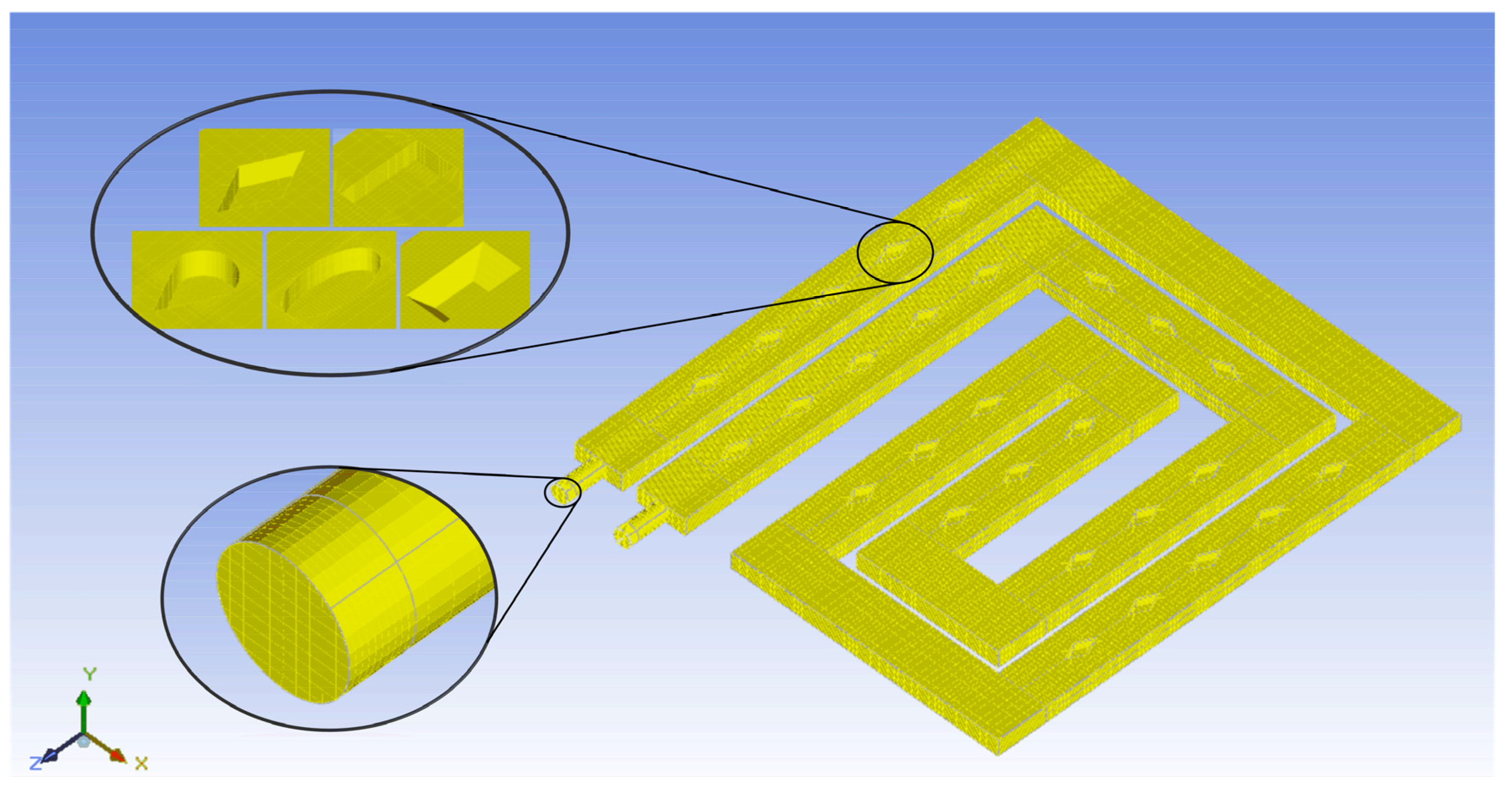
2.3. Grid Independence

The Mesher-HD mesh type is used for the computational domain of the numerical model, and the mesh structure of the fluid domain is shown in Figure 3. The mesh structure is generated using the mesh module in ANSYS-Icepak. Then, in order to reduce the time of the numerical simulation and, at the same time, to ensure the accuracy of the numerical simulation results, a grid-independence test should be performed. In this study, the Nusselt number and the friction coefficient were identified as parameters for mesh-independent analysis. Based on Figure 4, the grid numbers of FC-DR, FC-RR, FC-ER, FC-DSR and FC-FR are 1827940, 1877290, 2199979, 2874057 and 2050923, respectively. The Nusselt number and the friction factor obtained from the calculations are within a 1% error range from the results obtained at the maximum grid number. Therefore, in this study, numerical simulations are carried out for the five enhanced radiators (FC-DR, FC-RR, FC-ER, FC-DSR, and FC-FR, respectively) using grid numbers of 1827940, 1877290, 2199979, 2874057, and 2050923. The difference in the number of grids in the heat sink can be attributed to the complexity of the rib structure.

3. Experimental Details

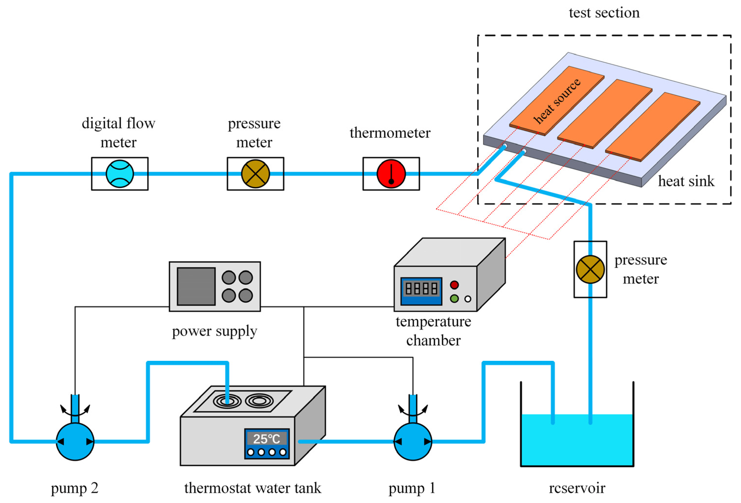
3.1. Experimental Setup

Figure 5 represents the schematic diagram of the experimental setup, which mainly consists of a power supply, liquid-cooled heat sink, simulated heat source, temperature chamber, reservoir, thermostat water tank, water pump, digital flow meter, thermometer, pressure meter, and K-type thermocouple. The water pump (Maximum flow rate of 2000 L/h) is utilized in the experiment to control the coolant’s input flow rate and propel it into the heat sink for forced conduction heat transfer. Simulated heat sources (Aluminum-cast heating plates with a maximum power of 1500 W) are used to provide the heat released during the operation of the electronics. A thermostat water tank (Accuracy ± 0.5%) keeps the temperature of the coolant entering the water-cooled heat sink at 25 °C. A bimetal thermometer (Accuracy ± 1.5%) is used to monitor the temperature of the coolant entering the heat sink. The entrance flow into the heat sink is observed using a digital flow meter (Flow range 4–50 L/min; Accuracy ± 1%). The pressure drop at the inlet and outflow of the cold plate is measured using a pressure meter (Maximum pressure 200 Kpa; Precision ± 0.4%). Additionally, one K-type thermocouple (Accuracy ± 0.75%) is installed at the heat sink’s outlet to gauge the temperature of the water flowing out of it, and nine K-type thermocouples are installed on its top surface to gauge the heat sink’s average surface temperature.

3.2. Processing of Data

3.2.1. Thermal-Performance Evaluation

A critical metric for assessing a heat sink’s thermal efficiency is the Nusselt number, whose formulation is:
N u = h D h λ f
where N u denotes the Nusselt number, h is the convection heat-transfer coefficient, λ f is the fluid’s thermal conductivity and D h is the hydraulic diameter.
The convective heat-transfer coefficient h is:
h = Q A Δ T = Q A ( T w , a v e T f , a v e )
where Q is the total heat exchange, A is the convective heat-exchange area, T w , a v e is the average temperature of the contact surface between heat source and heat sink and T f , a v e is the average fluid temperature.
Q = m ˙ × C p × T f , o u t T f , i n = v ˙ × ρ f × C p × T f , o u t T f , i n
where m ˙ denotes the mass flow rate, C p denotes the fluid’s specific heat capacity, v ˙ denotes dthe volume flow rate and ρ f denotes the fluid density.
T f , a v e = T f , i n + T f , o u t 2
where T f , i n is the temperature of the fluid at its inlet, and T f , o u t is the temperature at its outflow.
From the measurements of nine thermocouples, the average temperature T w , a v e may be determined as follows:
T w , a v e = T w , 1 + T w , 2 + + T w , 9 9
The greatest temperature difference between the heated surfaces of the heat sinks reveals temperature non-uniformity, which is an essential metric for assessing the thermal performance of the heat sinks. The lower the number, the more uniform the heat sink’s temperature distribution. It is written as follows:
Δ T = T w , m a x T w , m i n
where ΔT, T w , m a x and T w , m i n are, respectively, the highest temperature difference, the highest temperature of the heated surface and the lowest temperature of the heated surface.

3.2.2. Hydraulic-Performance Evaluation

The Reynolds number is a number without dimensions that indicates the condition of fluid flow and is defined as:
R e = ρ f u i n D h μ
where Re is the inlet Reynolds number, u m is the average fluid velocity in the flow channel, μ is the dynamic viscosity of the fluid and D h is the hydraulic diameter of the flow channel.
The Darcy friction factor, which is defined as follows, is an essential statistic for analyzing the flow properties of heat-sink flow channels:
f = 2 Δ P ρ f L c h D h u i n 2
where ΔP denotes the pressure drop at the heat sink’s inlet and outflow, L c h denotes the channel’s length and f denotes the friction factor.
The hydraulic diameter D h is:
D h = 2 W c H c W c + H c
where W c is the channel’s width, and H c is the channel’s height.
The pressure drop ΔP between the heat sink’s inlet and outflow is defined as:
Δ P = P i n P o u t
where P i n denotes the inlet pressure, and P o u t denotes the outlet pressure.

3.2.3. Comprehensive Performance Assessment

The complete performance may be determined using the performance evaluation criteria (PEC), which is a comprehensive performance-assessment index at equivalent pump power, in addition to investigating the heat-transfer performance and flow characteristics of the heat sink alone. When using this indicator, the Reynolds number and the Prandtl number of the fluid in the reinforced heat sink and the SFC should be the same [34].
P E C = ( N u R N u s ) ( f R f s ) 1 / 3
where the subscript R corresponds to the reinforced flow channel, and the subscript S corresponds to the smooth flow channel.
If PEC < 1, it signifies that the reinforced flow channel’s performance after structural optimization is poorer than that of the SFC, resulting in negative optimization. If PEC > 1, it signifies that the reinforced flow channel’s performance after structural optimization is superior to that of the SFC, achieving positive optimization, and the bigger the PEC value, the greater the comprehensive performance.
The PEC depends on the first rule of thermodynamics to assess the overall performance of heat-sink reinforced channels, taking only energy quantity into account but not energy-quality fluctuation. For a more detailed examination of the degree to which thermal energy is utilized during fluid flow and heat transfer in the channel, the entropy-generation analysis technique [35], which is based on the second law of thermodynamics, was used to assess the performance of the reinforced heat sink.
Entropy generation caused by fluid heat exchange:
S T = Q T f , a v e Q T w , a v e = Q ( T w , a v e T f , a v e ) T w , a v e T f , a v e
Entropy generation of frictional losses caused by fluid flow:
S P = m ˙ ρ f T f , a v e P
Rate of total entropy generation in the heat-sink flow channel:
S g = S T + S P = Q ( T w , a v e T f , a v e ) T w , a v e T f , a v e + m ˙ ρ f T f , a v e P
where S g , S T and S P are, respectively, the rate of total entropy generation, the heat-transfer entropy generation and the flow entropy generation.
In addition, the augmentation entropy-generation number is developed to put the rate of entropy generation into a numerical form.
N s = S g , R S g , S
where N s is the augmentation entropy-generation number of the enhanced flow channel.
If N s is smaller than 1, it signifies that the fluid in the reinforced flow channel causes less irreversible loss than the fluid in the smooth flow channel.

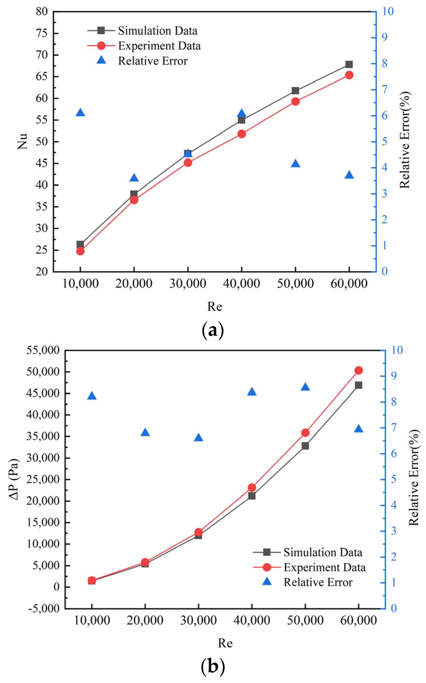
3.3. Numerical Model Validation and Uncertainty Analysis

The reinforced heat sink with diamond-shaped ribs (FC-DR) was tested experimentally. Since the fluid velocity inside the heat sink cannot be measured, the Nusselt number and pressure drop were utilized as measurement parameters in this work to verify the computer-simulation model. Figure 6 depicts a comparison of the experimental results with the Nusselt number and pressure-drop values. It can be observed that the simulated and experimental findings reveal a consistent trend of variation. Moreover, the maximum deviation of both the Nusselt number and the pressure drop are controlled within 10% of each other. Taking into account the uncertainty in the data as well as the assumptions used in the computer simulations, these deviations are considered to be within the permissible range. This validates the numerical model’s stability and ensures that it fits the computational standards for engineering applications.
U = U 1 2 + U 2 2
Uncertainty analysis is required in every experimental study, as it is necessary to ensure the reliability of experimental results. This experiment summarizes the uncertainty of the Nusselt number and the pressure drop during the measurement. It has the following two main factors: first, the uncertainty of the stability of multiple measurements of the measured value, U1, and second, the uncertainty of the error of the test equipment, U2. On the basis of Equation (20), the measurement uncertainties of the relevant performance parameters are calculated to be a 8.06% maximum error for the Nusselt number and 5.64% for the pressure drop.

4. Results and Discussion

4.1. Basic Performance Analysis

The preceding section’s numerical model was utilized to compare the thermal and hydraulic performance of SFC and other reinforced heat sinks. At a constant heat-flow density and an inlet cooling water temperature of 25 °C, the influence of flow velocity and rib structure was examined.

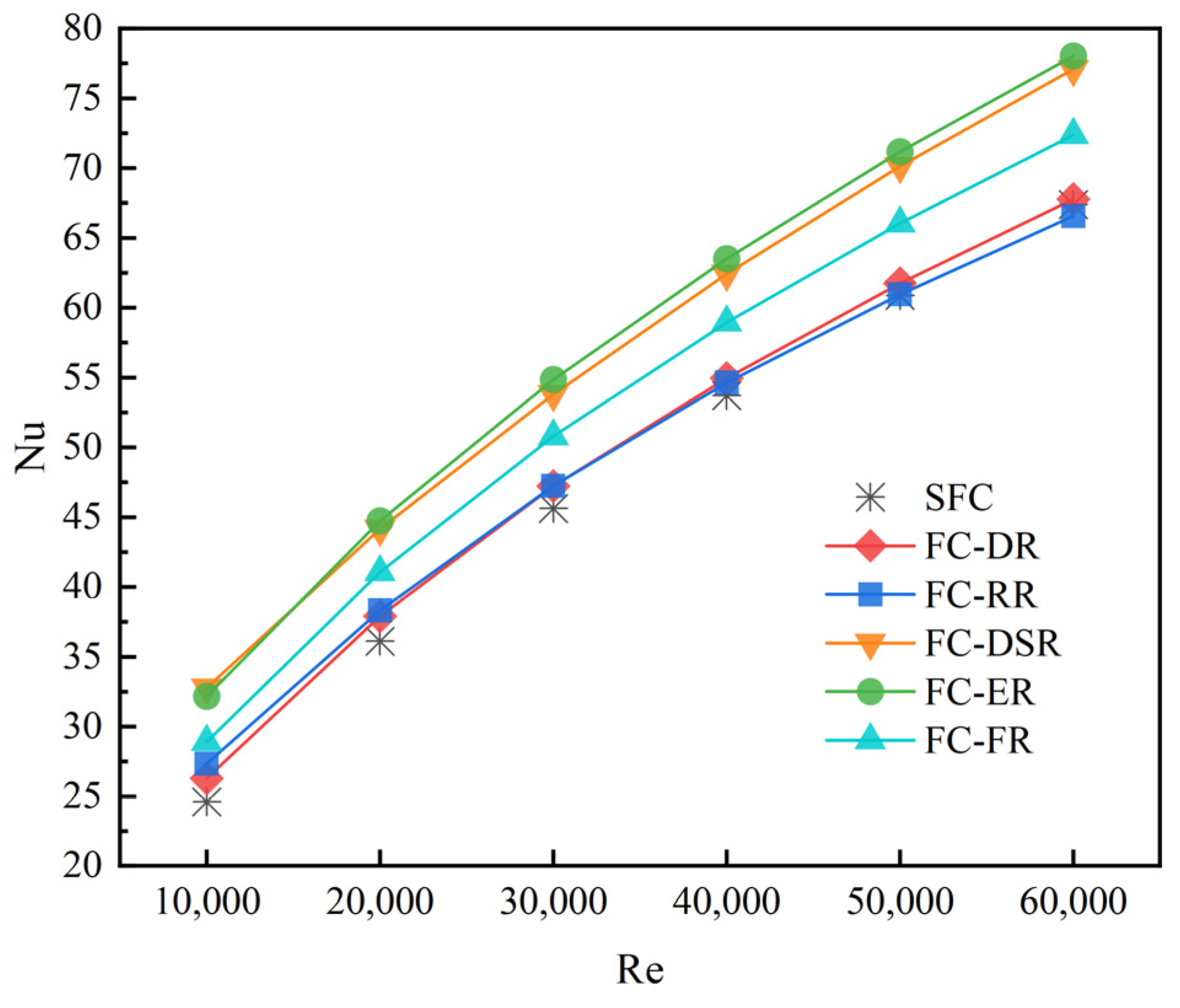
4.1.1. Thermal-Performance Analysis

Figure 7 illustrates the temperature distribution clouds for the SFC and the different reinforced heat sinks at the heated surface of the heat sink for a Reynolds number of 20,000. According to Figure 7, the lowest temperature is situated in the lower left corner of the heat sink, immediately above the channel inlet. The maximum temperature is found beneath the second heat source. This is due to the coolant’s temperature steadily increasing in the direction of fluid flow, and the second heat source is put at the finish of the flow channel. It can be noticed that the rib structure can greatly affect the heat sink’s surface temperature. This may be seen in the heat sink’s decreased temperature non-uniformity and lower maximum surface temperature. The reason for this is that the regular setting of ribs in the flow channel not only improves fluid mixing, but also periodically and effectively destroys the fluid’s thermal boundary layer, allowing the thermal boundary layer’s development to interrupt and redevelop, causing the strengthened heat sinks to have a lower temperature than the SFC. Additionally, the heat sink’s thermal performance can be impacted by the configuration of the ribs. As seen in Figure 7, the employment of diamond and rectangular ribs resulted in only a small increase in the thermal efficiency of the heat sink. The employment of elliptic, drop-shaped and frustum ribs can considerably increase the heat sink’s heat-transmission performance. The most favorable temperature distribution and greatest temperature of 47.51 °C, which was the lowest temperature of all the flow-channel designs, were found in the FC-ER.
Temperature non-uniformity is an essential metric to consider when assessing a heat sink’s thermal performance. Lower temperature non-uniformity reduces thermal stress and extends the life of electronic devices. Figure 8 depicts how the maximum temperature difference varies with the Reynolds number for various flow-channel configurations. In general, lowering the temperature non-uniformity may be accomplished by raising the Reynolds number. However, the effect of reducing temperature non-uniformity can be achieved more efficiently by using a reasonable arrangement of ribs. For example, FC-ER, FC-DSR and FC-FR still have lower temperature non-uniformity than the SFC with a Reynolds number of 60,000 when their Reynolds number is 40,000. As shown in Figure 8, the temperature uniformity of FC-DSR is optimum when Re = 10,000; when Re ≥ 20,000, FC-ER has superior temperature uniformity to FC-DSR. The above conclusion coincides with the phenomenon in Figure 7.
Figure 9 illustrates the influence of rib form on the average temperature at various Reynolds numbers. As seen in Figure 9, when the Reynolds number grows, the average temperature lowers, and the disparity between the average temperatures of distinct flow channels shrinks. The average temperature drops as the Reynolds number rises because convective heat transfer is improved. The average temperature of the SFC is the highest over the whole spectrum of Reynolds numbers examined, but the average temperatures of FC-DR and FC-RR deviate very little from that of the SFC. It is worth mentioning that FC-ER has the lowest average temperature.
Figure 10 shows the correlation between the SFC and other reinforced flow channels’ Nusselt number and Reynolds number. As seen in Figure 10, the Nusselt number of all the flow-channel configurations increases with an increasing Reynolds number. This is due to the flow velocity being positively correlated with the Reynolds number; in addition, the degree of turbulence increases when the flow velocity increases, and the mixing effect between hot and cold fluids is enhanced, thus increasing the Nusselt number. In general, heat sinks with added ribs have a higher Nusselt number than the SFC. It is important to note that there is very little difference in the Nusselt number between FC-DR, FC-RR and the SFC. In addition, the Nusselt number of FC-RR is 66.56 when Re = 60,000, which is lower than the Nusselt number of the SFC at 67.39. This shows that the addition of rectangular and diamond ribs in the flow channel is not effective in enhancing the heat transfer. As observed in Figure 10, the largest Nusselt number in the reinforced flow channels is that for FC-ER, followed by FC-DSR, and then FC-FR. Therefore, the heat-transfer effect of elliptic ribs is better than for other shapes of ribs.

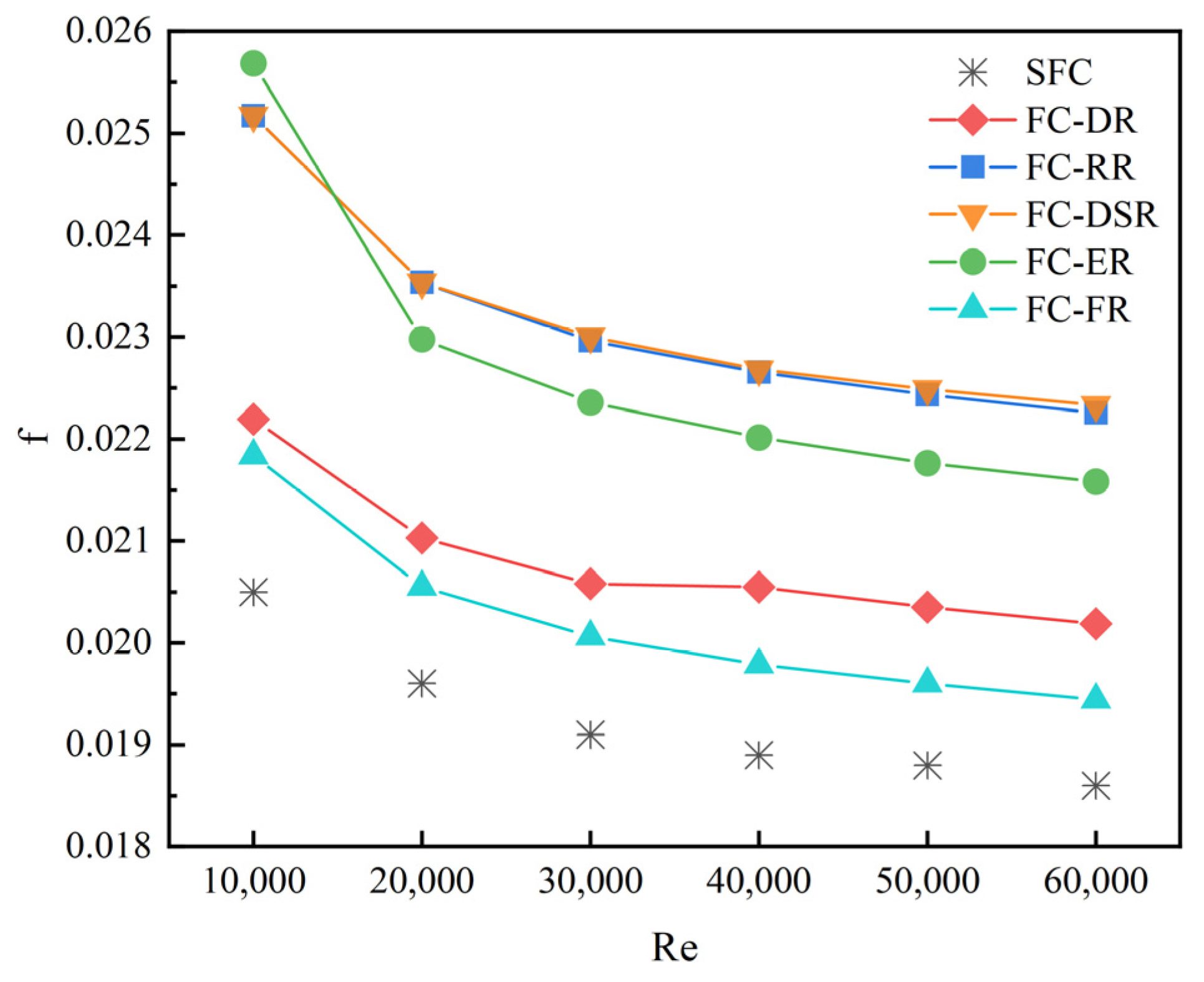
4.1.2. Hydraulic-Performance Analysis

Figure 11 illustrates the pressure distribution clouds for the SFC and the reinforced heat sinks at a Reynolds number of 20,000. As shown in Figure 11, the highest pressure is at the heat sink’s entrance, and the pressure of the fluid decreases with the direction of fluid flow. Compared with reinforced heat sinks, the SFC has a substantially lower pressure drop. Figure 11 clearly shows that the fluid pressure of FC-RR, FC-DSR and FC-ER is much greater than that of FC-DR and FC-FR. This is due to the fact that rectangular, drop-shaped and elliptic ribs form a large area of stagnation zone at the rib tips. The small rib-tip area and streamlined body of the diamond ribs ensure smooth reattachment and do not create large resistance to pressure-driven fluids. The frustum ribs have very little obstruction to the fluid because the angle with the fluid-flow direction is greater than 90°.
Figure 12 depicts the change in the inlet and output pressure drop for various flow-channel configurations as the Reynolds number changes from 10,000 to 60,000. Every flow channel has a greater pressure drop as the Reynolds number rises. As seen in Figure 12, the pressure drop of the SFC is always the lowest. In addition, the form of the ribs has a crucial role in the pressure drop of the heat sink. The pressure drop in different rib flow channels, from large to small, is drop-shaped, rectangular, elliptic, diamond and frustum, according to the data. This conclusion corroborates the analytical results in Figure 11.
In Figure 13, the curves of the friction factor with the Reynolds number in different flow channels are shown. It can be found that the friction factor for all flow channels first declines rapidly with increasing Reynolds number and then levels off in the high Reynolds number range. For the flow channel with ribbed structure, the friction factor inside the flow channel is much larger than that of the flow channel without ribbed columns due to the presence of ribbed columns, which block the flow of the mainstream fluid and enhance the perturbation. Among them, the friction factor of FC-DSR and FC-RR are similar and maximum, and the friction factor of FC-FR is the minimum.

4.2. Comprehensive Performance Analysis

Heat-transfer enhancement is typically accompanied by a boost in pressure loss; thus, while optimizing the flow-channel layout, we want to achieve not just improved heat-transfer efficiency but also as low a pressure cost as feasible. The next step is to compare the reinforced flow channels with the SFC from the perspective of comprehensive performance.

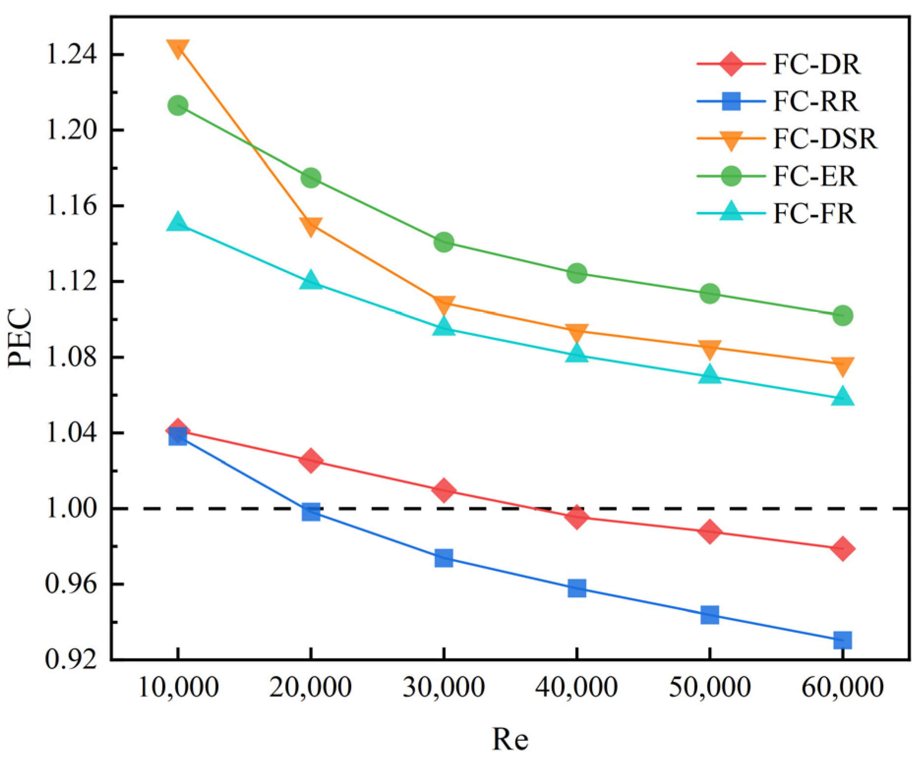
4.2.1. Performance Evaluation

Figure 14 reflects the PEC corresponding to each enhanced flow channel for various Reynolds values. As shown in Figure 14, the PEC values show a decreasing trend with the increase in Reynolds number. It can be concluded that a single increase in fluid velocity does not improve the comprehensive performance of the heat sink. In addition, the PEC values of FC-RR and FC-DR are lower than one in the high Reynolds number range, so it can be inferred that the rectangular and diamond ribs have a limited effect on the optimization of the flow channel. It is worth noting that FC-DSR has higher overall performance evaluation criteria than FC-ER when Re = 10,000; however, with a further increase in the Reynolds number, the PEC value of FC-ER is larger than that of FC-DSR. In summary, FC-ER has the best balance between enhanced heat transfer and flow losses in the simulated Reynolds number range.

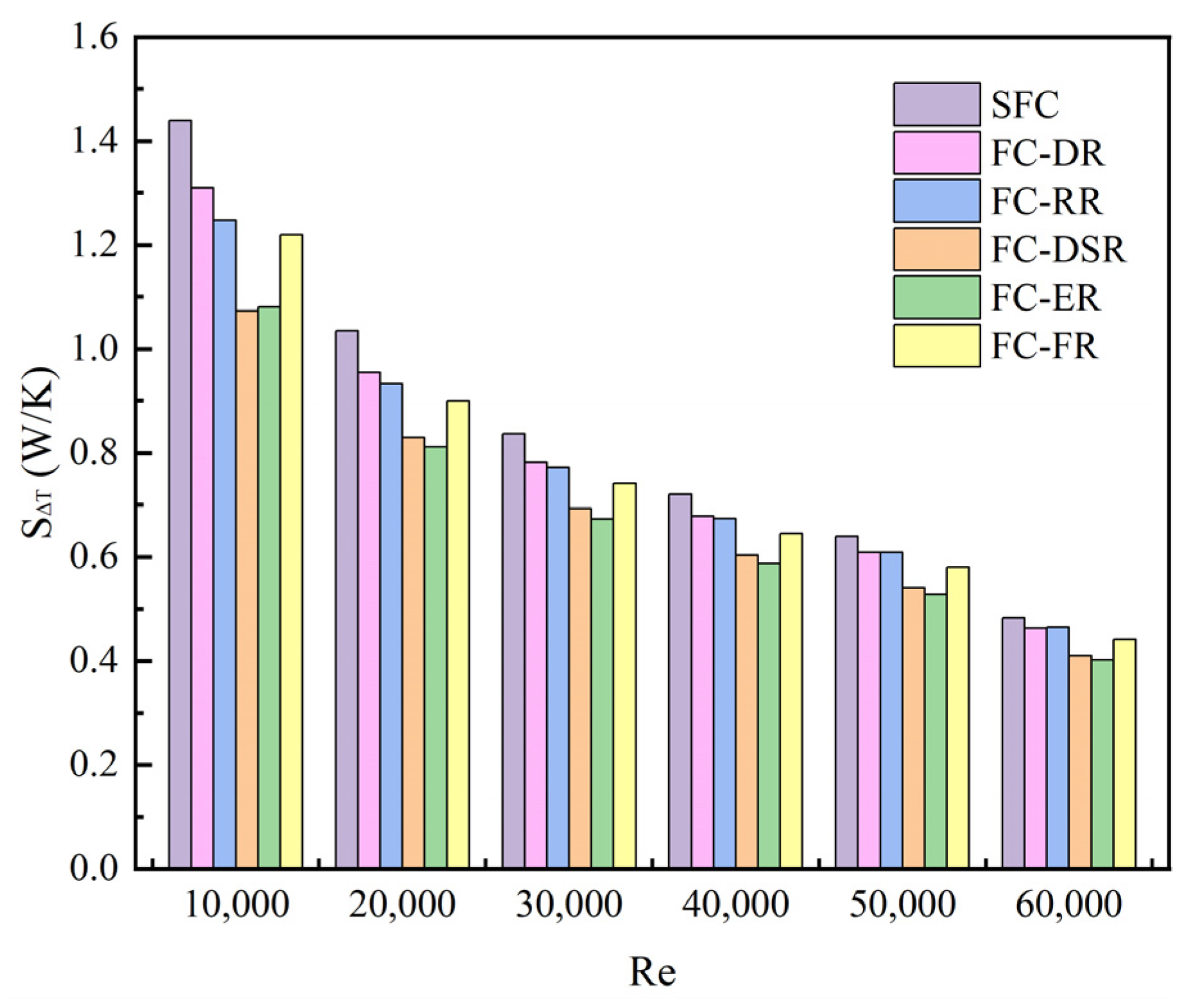
4.2.2. Analysis of Entropy Generation

Figure 15 shows how entropy generation due to heat transfer varies with the Reynolds number for all flow channels. The entropy generation in the flow channel owing to heat transfer reduces as the Reynolds number rises, which is apparent in Figure 15. Because the heat removed by the fluid rises as the Reynolds number rises, the average temperature of the heating surface lowers more than the average temperature of the fluid. From Formula (16), the heat-transfer entropy generation decreases. Additionally, Figure 15 demonstrates that the heat-transfer entropy generation in all the reinforced flow channels is smaller than that in the SFC. This is because the reinforced heat sink has a more uniform heating surface temperature and a lower average temperature at the same Reynolds number. Within the Reynolds number range studied, the heat-transfer entropy generation of FC-DSR is the smallest when Re = 10,000, followed by FC-ER. However, when the Reynolds number increases, the heat-transfer entropy production of FC-ER becomes lower than that of FC-DSR. Therefore, it can be concluded that FC-ER has the least irreversible losses in the procedure of heat transfer, and its heat-transfer performance is better than that of other enhanced heat sinks.
Figure 16 depicts the relationship between flow entropy generation and the Reynolds number for all flow channels. As observed in Figure 16, the flow entropy generation of the flow channel increases with an increase in Reynolds number, and the difference between the flow entropy generation increases as well. The flow entropy generation of the SFC is smaller than that of all reinforced heat sinks. This is due to the rib structure impeding the fluid flow; the shear force inside the fluid increases, the mutual collision between the fluid is intense, and the momentum loss increases. In general, among the different enhanced flow channels, FC-FR has the smallest entropy generation due to flow, followed by FC-DR, then FC-ER, while the largest is that of FC-RR and FC-DSR. In the simulated Reynolds number range, the flow entropy generation of FC-RR and FC-DSR is essentially the same.
We analyzed the role played by different ribs in the irreversible losses of the convection heat-transfer process. Figure 17 shows how the augmentation entropy-generation number varies with the Reynolds number for each augmented flow channel. It is often assumed that the smaller the augmentation entropy-generation number, the higher the corresponding heat-transfer efficiency. As observed in Figure 17, the augmentation entropy-generation numbers for all the reinforced flow channels are less than one in the Reynolds number range under discussion, which indicates that the irreversible losses caused by the fluid in the reinforced heat sinks are less than those in the SFC. Additionally, when the Reynolds number grows, the augmentation entropy-generation number of all the flow channels increases continually. When Re = 60,000, the augmentation entropy-generation number of FC-RR and FC-DR approaches one. This suggests that the ribs are more effective in low-Reynolds-number cases than in high-Reynolds-number ones. As shown in Figure 17, FC-ER has the smallest augmentation entropy-generation number, which means the least loss of available energy for the same gain.

5. Conclusions

The flow and heat transfer of a double-helical-type channel heat sink with varied shaped ribs positioned on the top wall were numerically modelled at a constant heat-flow density and a turbulent Reynolds number of 10,000–60,000. The FC-DR testing findings were utilized to validate the numerical model’s dependability. There was found to be significant consistency between the computational and experimental results. The maximum deviation of both the Nusselt number and the pressure drop was controlled within 10% of each other. This indicates that the numerical simulation findings are credible. The study yielded a number of significant findings:
(1)
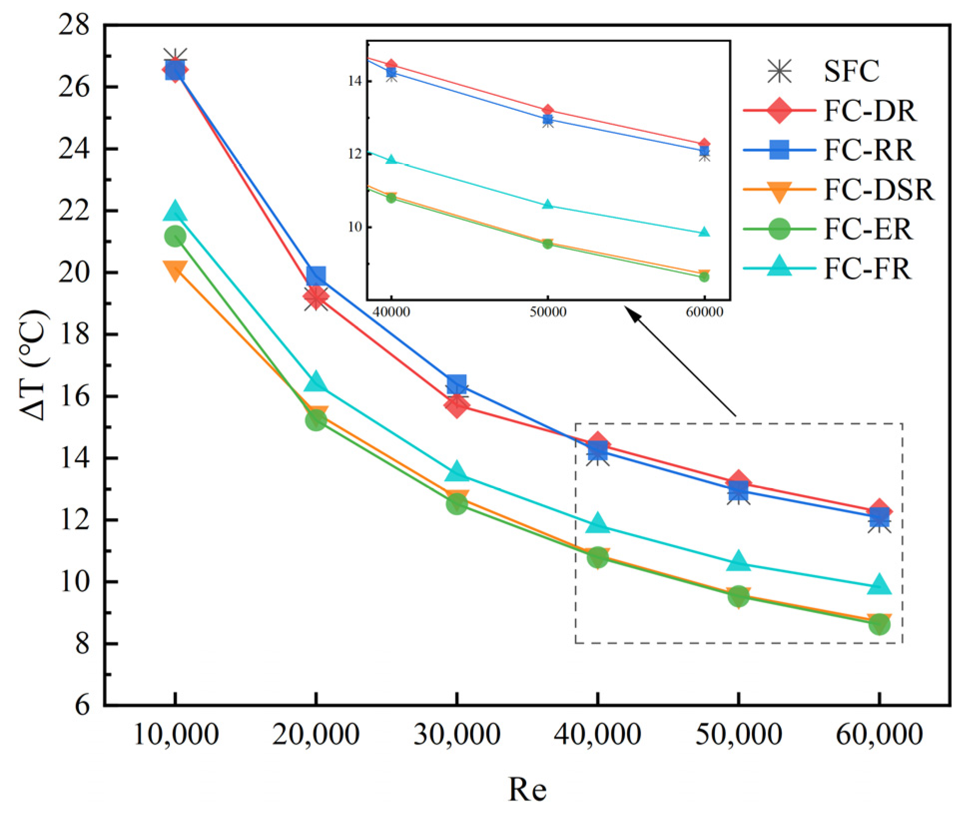
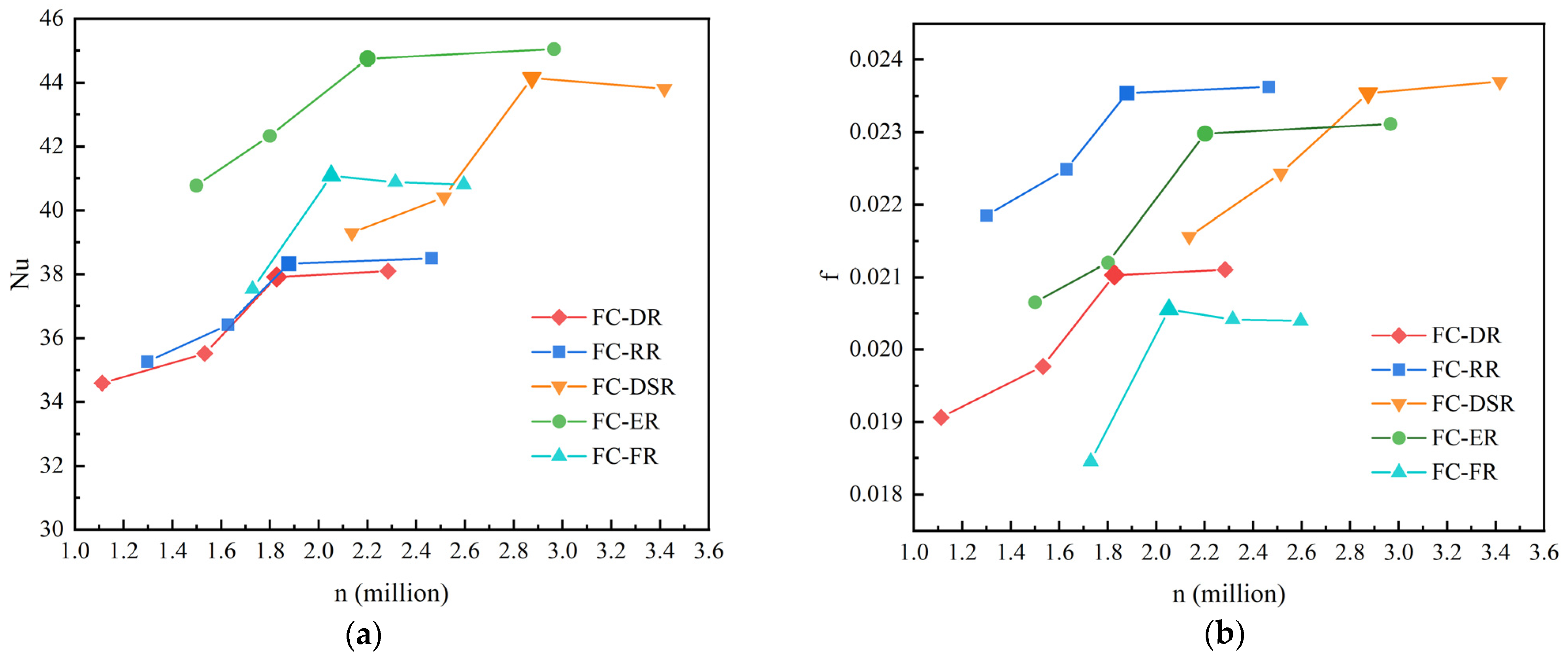
Channels with ribbed construction outperform SFC in terms of thermal performance. However, diamond and rectangular ribs have little influence in boosting the heat sink’s thermal performance. The elliptic, drop-shaped and frustum ribs considerably increase the heat sink’s heat-transmission performance. FC-ER offers the lowest average temperature and the highest temperature uniformity, with a Nusselt number improvement percentage ranging from 15.80% to 30.77%.
(2)
The inlet and outlet pressure drops and the friction factor of the rib structure flow channel are larger than those of the SFC.
(3)
For the smooth flow channel, it is more effective to improve the comprehensive performance by arranging elliptic, drop-shaped and frustum ribs. FC-ER provides the best balance between enhanced heat transfer and flow losses over the range of Reynolds numbers studied.
(4)
For all flow channels with ribbed structures, the augmentation entropy-generation number is below one. From the viewpoint of entropy generation, flow channels with ribbed structures are all superior to SFC. In generally, FC-ER has the smallest augmentation entropy-generation number, which means the least loss of available energy for the same gain.

Author Contributions

Conceptualization, L.H. and L.Z.; methodology, X.H.; software, L.H.; validation, F.C. and X.Z.; writing—original draft preparation, L.H. and F.C.; supervision, X.H. and X.Z.; project administration, X.H.; funding acquisition, X.H. and L.Z. All authors have read and agreed to the published version of the manuscript.

Funding

This research was funded by the National Natural Science Foundation of China (grant number: 51665052) and the Corps Outstanding Talent Support Program (Youth Program), China, (grant number: CZ001320).

Data Availability Statement

Data are contained within the article.

Conflicts of Interest

Authors Feng Chen and Xinwang Zhang were employed by Urumqi Jinfeng Tianyi Wind Power Co., Ltd. The remaining authors declare that the research was conducted in the absence of any commercial or financial relationships that could be construed as a potential conflict of interest.

Nomenclature

Variables
Aarea (m2)
Cpspecific heat capacity (J/(kg*k))
Dhhydraulic diameter (m)
hheat-transfer coefficient (W/m2*K)
Hcheight of the channel (m)
Lchlength of the flow channel (m)
m ˙ mass flow rate (kg/s)
Nsthe augmentation entropy-generation number
NuNusselt number
Ppressure (Pa)
Qheat-transfer gain(W)
ReReynolds number
Sgthe total entropy-generation rate (W/ K)
TTemperature (°C)
uflow velocity (m/s)
u,v,wvelocity at the x, y z directions, respectively (m/s);
x,y,zCartesian coordinates;
Greek symbols
λfluid thermal conductivity (W/m*K)
μfluid dynamic viscosity (Pa*s)
ρdensity (kg/m3)
f friction factor
ΔPpressure drop (Pa)
ΔTtemperature non-uniformity (°C)
Subscripts
ffluid
Rribbed
Soriginal
wwall
ininlet
aveaverage

References

  1. Anandan, S.S.; Ramalingam, V. Thermal Management of Electronics: A review of Literature. Therm. Sci. 2008, 12, 5–26. [Google Scholar] [CrossRef]
  2. Huai, W.; Liserre, M.; Blaabjerg, F. Toward Reliable Power Electronics: Challenges, Design Tools, and Opportunities. IEEE Ind. Electron. Mag. 2013, 7, 17–26. [Google Scholar]
  3. Ui-Min, C.; Blaabjerg, F.; Kyo-Beum, L. Study and Handling Methods of Power IGBT Module Failures in Power Electronic Converter Systems. IEEE Trans. Power Electron. 2015, 30, 2517–2533. [Google Scholar]
  4. Mohammadian, S.K.; Zhang, Y. Thermal management optimization of an air-cooled Li-ion battery module using pin-fin heat sinks for hybrid electric vehicles. J. Power Sources 2015, 273, 431–439. [Google Scholar] [CrossRef]
  5. Teng, H.; Yeow, K. Design of direct and indirect liquid cooling systems for high-capacity, high-power lithium-ion battery packs. SAE Int. J. Altern. Powertrains 2012, 1, 525–531. [Google Scholar] [CrossRef]
  6. Yeo, D.Y.; No, H.C. Modeling film boiling within chimney-structured porous media and heat pipes. Int. J. Heat Mass Transf. 2018, 124, 576–585. [Google Scholar] [CrossRef]
  7. Mira-Hernandez, C.; Clark, M.D.; Weibel, J.A.; Garimella, S.V. Development and validation of a semi-empirical model for two-phase heat transfer from arrays of impinging jets. Int. J. Heat Mass Transf. 2018, 124, 782–793. [Google Scholar] [CrossRef]
  8. Lyu, Y.; Siddique, A.R.M.; Majid, S.H.; Biglarbegian, M.; Gadsden, S.A.; Mahmud, S. Electric vehicle battery thermal management system with thermoelectric cooling. Energy Rep. 2019, 5, 822–827. [Google Scholar] [CrossRef]
  9. Bilen, K.; Cetin, M.; Gul, H. The investigation of groove geometry effect on heat transfer for internally grooved tubes. Appl. Therm. Eng. 2009, 29, 753–761. [Google Scholar] [CrossRef]
  10. Mesalhy; Aziz, S.S.A.; El-Sayed, M.M. Flow and heat transfer over shallow cavities. Int. J. Thermal. Sci. 2021, 49, 514–521. [Google Scholar] [CrossRef]
  11. Chai, L.; Xia, G.D.; Zhou, M.Z. Numerical simulation of fluid flow and heat transfer in a microchannel heat sink with offset fan-shaped reentrant cavities in sidewall. Int. Commun. Heat Mass Transf. 2011, 38, 577–584. [Google Scholar] [CrossRef]
  12. Zhou, J.; Hatami, M.; Song, D. Design of microchannel heat sink with wary channel and its time-efficient optimization with combined RSM and method. Int. J. Heat Mass Tran. 2016, 103, 715–724. [Google Scholar] [CrossRef]
  13. Mohammed, H.A.; Gunnasegaran, P.; Shuaib, N.H. Influence of channel shape on the thermal and hydraulic performance of microchannel heat sink. Int. Commun. Heat Mass Transfer. 2011, 38, 474–480. [Google Scholar] [CrossRef]
  14. Mohammed, H.A.; Gunnasegaran, P.; Shuaib, N.H. Numerical simulation of heat transfer enhancement in wavy microchannel heat sink. Int. Commun. Heat Mass Transfer. 2011, 38, 63–68. [Google Scholar] [CrossRef]
  15. Hua, J.; Li, G.; Zhao, X.; Li, Q.; Hu, J. Study on the flow resistance performance of fluid cross various shapes of micro-scale pin fin. Appl. Therm. Eng. 2016, 107, 768–775. [Google Scholar] [CrossRef]
  16. Xie, G.; Liu, X.; Yan, H.; Qin, J. Turbulent flow characteristics and heat transfer enhancement in a square channel with various crescent ribs on one wall. Int. J. Heat Mass Transf. 2017, 115, 283–295. [Google Scholar] [CrossRef]
  17. Gholami, M.R.; Akbari, O.A.; Marzban, A. The effect of rib shape on the behavior of laminar flow of oil/MWCNT nanofluid in a rectangular microchannel. J. Therm. Anal. Calorim. 2017, 134, 1611–1628. [Google Scholar] [CrossRef]
  18. Chai, L.; Xia, G.D.; Wang, H.S. Numerical study of laminar flow and heat transfer in microchannel heat sink with offset ribs on sidewalls. Appl. Therm. Eng. 2016, 92, 32–41. [Google Scholar] [CrossRef]
  19. Jaffal, H.M.; Mahmoud, N.S.; Imran, A.A.; Hasan, A. Performance enhancement of a novel serpentine channel cooled plate used for cooling of Li-ion battery module. Int. J. Therm. Sci. 2023, 184, 107955. [Google Scholar] [CrossRef]
  20. Bejan, A.; Pfister, P.A. Evaluation of heat transfer augmentation techniques based on their impact on entropy generation. Lett. Heat Mass Transf. 1980, 7, 97–106. [Google Scholar] [CrossRef]
  21. He, Y.-L.; Tang, S.-Z.; Tao, W.-Q.; Li, M.-J.; Wang, F.-L. A general and rapid method for performance evaluation of enhanced heat transfer techniques. Int. J. Heat Mass Tran. 2019, 145, 118780. [Google Scholar] [CrossRef]
  22. Liu, W.; Liu, P.; Wang, J.B. Exergy destruction minimization: A principle to convective heat transfer enhancement. Int. J. Heat Mass Tran. 2018, 122, 11–21. [Google Scholar] [CrossRef]
  23. Ji, W.T.; Jacobi, A.M.; He, Y.L. Summary and evaluation on single-phase heat transfer enhancement techniques of liquid laminar and turbulent pipe flow. Int. J. Heat Mass Tran. 2015, 88, 735–754. [Google Scholar] [CrossRef]
  24. Wang, F.; Wang, G. Heat transfer augmentation and entropy generation analysis of a helically coiled tube with internal longitudinal fins. Chem. Eng. Technol. 2011, 34, 1876–1882. [Google Scholar] [CrossRef]
  25. Datta, V.; Sharma, D.; Sanyal. A conjugate heat transfer analysis of performance for rectangular microchannel with trapezoidal cavities and ribs. Int. J. Therm. Sci. 2019, 138, 425–446. [Google Scholar] [CrossRef]
  26. Guo, K.; Li, Q.; Liu, B.T. A novel design method based on flow pattern construction for flow passage with low flow drag and pressure drop. Chem. Eng. Sci. 2015, 135, 89–99. [Google Scholar] [CrossRef]
  27. Guo, K.; Liu, B.T.; Li, X. Flow pattern construction-based tubular heat transfer intensification using calculus of variations. Chem. Eng. Sci. 2016, 152, 568–578. [Google Scholar] [CrossRef]
  28. Guo, K.; Qi, W.Z.; Liu, B.T. Optimization of an “area to point” heat conduction problem. App. Therm. Eng. 2016, 93, 61–71. [Google Scholar] [CrossRef]
  29. Zhao, N.; Guo, L.; Qi, C.; Chen, T.; Cui, X. Experimental study on thermo-hydraulic performance of nanofluids in CPU heat sink with rectangular grooves and cylindrical bugles based on exergy efficiency. Energy Convers. Manag. 2019, 181, 235–246. [Google Scholar] [CrossRef]
  30. Zhao, N.; Qi, C.; Chen, T.; Tang, J.; Cui, X. Experimental study on influences of cylindrical grooves on thermal efficiency, exergy efficiency and entropy generation of CPU cooled by nanofluids. Int. J. Heat Mass Transf. 2019, 135, 16–32. [Google Scholar] [CrossRef]
  31. Khalifa, M.A.; Jaffal, H.M. Effects of channel configuration on hydrothermal performance of the cylindrical mini-channel heat sinks. Appl. Therm. Eng. 2019, 148, 1107–1130. [Google Scholar] [CrossRef]
  32. He, L.; Hu, X.; Zhang, L. Performance Evaluation and Optimization of Series Flow Channel Water-Cooled Plate for IGBT Modules. Energies 2023, 16, 5205. [Google Scholar] [CrossRef]
  33. Xie, X.L.; Tao, W.Q.; He, Y.L. Numerical Study of Turbulent Heat Transfer and Pressure Drop Characteristics in a Water-Cooled Minichannel Heat Sink. J. Electron. Packag. 2017, 129, 247–255. [Google Scholar] [CrossRef]
  34. Webb, R.L. Performance evaluation criteria for use of enhanced heat transfer surfaces in heat exchanger design. Int. J. Heat Mass Transf. 1981, 24, 715–726. [Google Scholar] [CrossRef]
  35. Xia, G.D.; Zhai, Y.L.; Cui, Z.Z. Characteristics of entropy generation and heat transfer in a microchannel with fan-shaped reentrant cavities and internal ribs. Sci. China Technol. Sci. 2013, 56, 1629–1635. [Google Scholar] [CrossRef]
Figure 1. Heat-sink schematic with five distinct rib configurations.
Processes 12 00598 g001
Figure 2. Local schematic of the flow channel with a rib structure.
Processes 12 00598 g002
Figure 3. Meshing in ANSYS-Icepak.
Processes 12 00598 g003
Figure 4. Grid-independence validation. (a) Nusselt number; (b) Friction factor.
Processes 12 00598 g004
Figure 5. The experimental setup’s schematic diagram.
Processes 12 00598 g005
Figure 6. Comparison of simulation and experiment data. (a) Nusselt number; (b) Pressure drop.
Processes 12 00598 g006
Figure 7. Temperature distribution for different channel configurations. (a) SFC; (b) FC-DR; (c) FC-RR; (d) FC-ER; (e) FC-DSR; and (f) FC-FR.
Processes 12 00598 g007
Figure 8. Influence of rib architecture on temperature non-uniformity.
Processes 12 00598 g008
Figure 9. Influence of rib architecture on the average temperature.
Processes 12 00598 g009
Figure 10. Influence of rib architecture on the Nusselt number.
Processes 12 00598 g010
Figure 11. Pressure distribution in different channel layouts. (a) SFC; (b) FC-DR; (c) FC-RR; (d) FC-ER; (e) FC-DSR; and (f) FC-FR.
Processes 12 00598 g011
Figure 12. Influence of rib architecture on the pressure drop.
Processes 12 00598 g012
Figure 13. Influence of rib architecture on the friction factor.
Processes 12 00598 g013
Figure 14. Influence of rib architecture on the performance evaluation criteria.
Processes 12 00598 g014
Figure 15. Influence of rib architecture on heat-transfer entropy generation.
Processes 12 00598 g015
Figure 16. Influence of rib architecture on flow entropy generation.
Processes 12 00598 g016
Figure 17. Influence of rib architecture on the augmentation entropy-generation number.
Processes 12 00598 g017
Table 1. The physical parameters of the material.
MaterialDensity
(kg/m3)
Specific Heat
(kJ/(kg·k))
Thermal
Conductivity
(w/m·k)
Dynamic
viscosity
(Ps·s)
6063 Al27100.902218-
Coolant997.04.20.6099.028 × 10−4
Disclaimer/Publisher’s Note: The statements, opinions and data contained in all publications are solely those of the individual author(s) and contributor(s) and not of MDPI and/or the editor(s). MDPI and/or the editor(s) disclaim responsibility for any injury to people or property resulting from any ideas, methods, instructions or products referred to in the content.

