Abstract
An efficient and accurate method for optimizing capsule-type plate heat exchangers is proposed in this paper. This method combines computational fluid dynamics simulation, a backpropagation algorithm and multi-objective optimization to obtain better heat transfer performance of heat exchanger structures. For plate heat exchangers, the heat transfer coefficient j and friction coefficient f are a pair of contradictory objectives. The optimization of capsule-type plate heat exchangers is a multi-objective optimization problem. In this paper, a backpropagation neural network was used to construct an approximate model. The plate shape was optimized by a multi-objective genetic algorithm. The optimized capsule-type plate heat exchanger has lower flow resistance and higher heat exchange efficiency. After optimization, the heat transfer coefficient is increased by 8.3% and the friction coefficient is decreased by 14.3%, and the heat transfer effect is obviously improved. Further, analysis of flow field characteristics through field co-ordination theory provides guidance for the further optimization of plates.
1. Introduction
The plate heat exchanger uses plates as the heat exchange surfaces; the gap between the plates is the heat exchange channel and heat transfer and convection heat transfer are the main heat exchange modes. With a compact structure and high heat transfer coefficient, it is widely used in industry. It has high economic and ecological benefits to improve its heat transfer effect and reduce energy consumption. Therefore, in recent years, researchers have conducted a lot of research on plate heat exchangers with different surfaces, hoping to improve the performance of plate heat exchangers.
Arsenyeva O et al. proposed a method for selecting a pillow-plate heat exchanger (PPHE) with a minimum heat transfer area, which is based on the mathematical model of thermal and hydraulic PPHE behavior. They discussed two case studies for water heating and crude oil preheat train operating conditions. The results show that PPHE has a higher velocity in the channel, a longer plate and a lower heat transfer area. It can be successfully applied to the conditions of distinctly different flow rates of cold and hot fluids [1,2]. M. Piper et al. proposed a method to determine the cross-sectional area of the hydraulic diameter and heat transfer area for pillow-plate geometries. Based on forming simulation, the method accurately reproduces the inherent three-dimensional wavy pillow channel by imitating the actual manufacturing process of pillow plates [3]. The authors proposed a method to enhance heat transfer in PPHE [4] and two methods for determining the heat transfer coefficient [5]. The CFD method was used to study the single-phase turbulent flow in the pillow plate, and the results were verified by experiments. A simple geometric improvement scheme is proposed, which improves the thermo-hydraulic performance of the pillow board significantly [6]. Tran JM et al. carried out an experimental study of internal-side heat transfer and pressure drop, and their results improve the understanding of the thermal–hydraulic characteristics of pillow plates [7]. Condensation experiments were carried out on a pilot scale using unconventional optical fiber measurement technology to determine the axial temperature distribution in the condensation channel. The heat transfer coefficient and pressure drop value on the cooling side were obtained based on laboratory-scale measurement and numerical simulation [8]. Shirzad M et al. investigated the effect of using different nanofluids as coolant fluids on the thermal performance of pillow-plate heat exchangers; then, three-dimensional numerical simulations of the heat transfer and pressure drop of three water-based nanofluids were carried out using commercial CFD software. Regarding the nanofluids, the results show that the heat transfer coefficient at a low Reynolds number can be significantly increased by increasing the volume concentration of nanoparticles in a certain range [9].
Song J et al. performed an experimental study and analysis of a novel multi-media plate heat exchanger, which is formed by a discontinuous-structure wave consisting of a convex sphere and a concave sphere; its performance is better than that of a chevron plate heat exchanger. Furthermore, a mechanism analysis of heat transfer enhancement showed that a spherical wave structure can reduce the local field synergy angle and improve the field synergy of the velocity vector and temperature gradient vector [10]. Pei B et al. proposed a honeycomb ultra-compact plate heat exchanger with a hexagonal channel as a heat exchanger of the supercritical CO2 (SCO2) Brayton cycle and carried out a numerical simulation. The results show that the buoyancy effect has a weak influence on heat transfer at a high temperature because the thermal properties of SCO 2 undergo little change. And, because of the remarkable buoyancy effect, the turbulent energy and the secondary flow intensity reach the maximum near the pseudo-critical point, which leads to the enhancement of heat transfer [11]. Wenjing DU et al. proposed a hexagonal spherical ribbed-plate heat exchanger. Thermodynamic analysis of the heat exchanger was carried out based on the entropy yield, and the flow of fluid in the channel formed by spherical ribs was analyzed using the finite volume method. The distribution of entropy production on the plate caused by finite temperature difference heat conduction and resistance was obtained, and the variation in entropy production with the Reynolds number was obtained [12]. Jamzad P et al. presented a new fabrication method for chevron-type plate heat exchangers and designed a custom-designed water–water experimental testbed to measure the performance of the proposed graphite plate heat exchanger. Compared with the commercially available unit, the proposed graphite plate heat exchanger shows identical thermal performance and a 26% higher pressure drop due to its narrower channel design [13]. Durmus A et al. studied the effects of the surface geometry of three different types of heat exchangers on heat transfer performance, friction coefficient and exergy loss [14].
Zhang C et al. studied the heat transfer and flow performance of a circular spot-type plate heat exchanger through numerical research and an experimental test, analyzed and discussed its parameters, and comprehensively analyzed the heat transfer performance of different plate heat exchangers by using the exergy and entransy principle. The results show that the plate heat exchanger has better heat transfer performance than the flat panel heat exchanger [15]. Jeong JY et al. used computational fluid dynamics (CFD) technology to analyze the heat transfer and pressure drop characteristics of three types of plate heat exchangers (V-shaped embossing, elliptic embossing and round embossing). The results show that the performance of the elliptical plate is better than that of the V-shaped plate in terms of heat transfer and pressure drop [16]. Jiang C et al. carried out an experimental study on the flow characteristics of a capsule-type plate heat exchanger to expand its application in phase-change heat transfer [17]. Zhang Y et al. proposed a capsule-type plate heat exchanger to address high-viscosity fluid, which has concave and convex ellipsoidal embossing like half capsules, and carried out a numerical study of single-phase flow and heat transfer in the channel. It was found that the main reason for heat transfer enhancement is eddy currents, one of which has a unique butterfly head [18]. Alqutub AM et al. measured the overall heat transfer coefficient, friction coefficient and effectiveness of a dimple-protrusion air-to-air counter-flow plate heat exchanger at low Reynolds number [19].
Kim M et al. conducted an experimental study on cross-flow air-cooled corrugated plate radiator. The results of the experiment showed that the heat transfer performance of the double-wave heat exchanger was improved by approximately 50% compared to the single-wave heat exchanger [20]. Doo JH et al. proposed a cross-corrugated primary surface heat exchanger and used three-dimensional numerical simulation to analyze the improved original surface geometry [21]. Lee JM et al. obtained different geometric shapes (sinusoidal and asymmetric) and valley shapes (linear and sinusoidal) of the parameterized cross-corrugated plate heat exchanger surfaces and provided high-resolution heat transfer distribution data obtained from experiments [22]. Kanaris AG et al. proposed a general method for optimizing the design of corrugated surface plate heat exchangers in accordance with the principle of sustainability. They utilized a CFD program to predict the heat transfer rate and pressure drop of these devices. The obtained results showed good agreement with experimental data [23]. Imran M et al. used the multi-objective genetic algorithm to optimize the thermal and hydraulic design of V-shaped plate heat exchangers and found a set of optimal solutions to balance the pressure drop and heat transfer. The sensitivity analysis of the geometric parameters of the heat exchanger to the thermal and hydraulic performance is carried out. The sensitivity analysis results show that the center distance of vertical holes, the plate distance and the number of hot plates have great influence on heat transfer and pressure drop [24]. Giurgiu O et al. carried out computational fluid dynamics (CFD) numerical study and experimental simulation on two kinds of microchannel models in plate heat exchanger structure. It shows that the geometrical structure of the plate had a significant effect on the flow of fluid in the channel, which highlighted the thermodynamic characteristics of the fluid [25]. Jin S et al. introduced the heat transfer of a frame plate. The analysis of the experimental results shows that the end plate is not adiabatic but acts as a heat sink due to the contact between adjacent plates. The heat conduction model is validated by experimental data. The results show that the heat dissipation efficiency of the end plate is a function of the convective heat transfer coefficient and the heat conduction resistance of the fluid [26]. Longo GA et al. introduced the experimental study of the “cross groove” surface to evaporation and condensation of refrigerant in the plate heat exchanger (PHE) with herringbone macro-ripple. The experimental results show that the “cross groove” surface is useful for evaporation and condensation, while the increase in surface roughness is only useful for evaporation. The increase in the heat transfer coefficient is higher than that of a simple heat transfer area [27]. Hu S et al. installed 12 thermocouples on the surface of the plate heat exchanger and in the cooling water channel to obtain the condensation heat transfer coefficient. The results show that, at all concentrations, the steam flow rate of local high-temperature gas chromatography decreases in turn and the content of high-temperature gas chromatography increases linearly with the increase in outlet steam quality [28]. Khodabandeh E et al. used the finite volume method and two-phase mixing model to simulate the turbulent flow and heat transfer of water silver nanofluid in a spiral heat exchanger with elliptic valves. The results showed that the flow and heat transfer characteristics depended on the height of the pillow, the concentration of nanoparticles and the Reynolds number [29]. Hwang et al. [30] designed a plate heat exchanger (PHE) with a dimple-protrusion-patterned surface and conducted an experimental study on it. The data analysis shows that the high heat transfer regions appear on the front part of the protrusion and the rear part of the dimple. The friction factor on the side of the dimple is around 1/3 of the friction factor on the side of the protrusion.
The above research method for a capsule-type plate heat exchanger is new, but the optimal structure may not be obtained. In this paper, the optimal size structure of the heat exchanger plate is designed with the aim of optimum heat transfer and resistance performance. At the same time, the field synergy theory is introduced to verify the comparison. The design method described in this paper can improve the heat transfer performance of the designed plate and save the research and development time and cost. The designed plate can further realize the miniaturization and light weight of the heat exchanger.
2. Structure Parameters
Heat exchangers play a key role in maintaining the temperature of working medium. In order to obtain better heat exchange performance, a new capsule-type plate heat exchanger is designed. The structure change has obvious influence on the working performance. The structure of capsule-type plate heat exchangers is optimized to obtain a high-efficiency heat exchanger. The three-dimensional model of the new inner capsule plate is shown in Figure 1 and Table 1. The cold and hot sides of the heat exchanger are coolant and working oil, respectively.
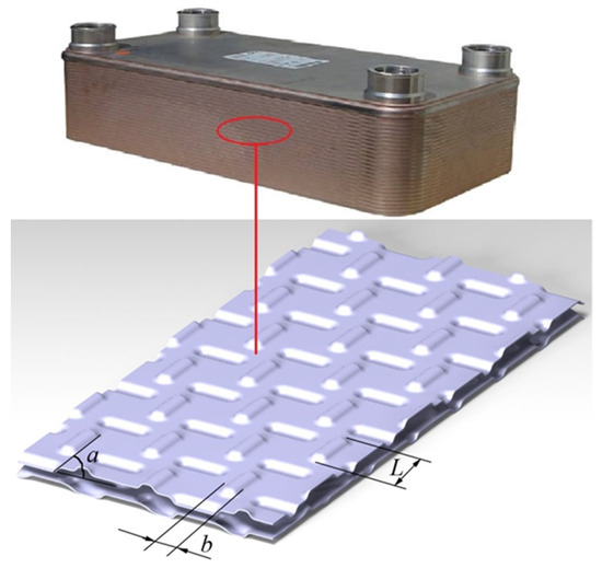
Figure 1.
The model of capsule-type plate heat exchanger.

Table 1.
Values of structural dimensions.
3. Simulating Calculation
3.1. Physical Condition Setting
The heat transfer process of a heat exchanger is an intricate physical process. The coolant is exchanged by heat flow. Therefore, CFD is used in this paper to solve the physical field of heat exchange. To save calculation time, the three-dimensional single-channel model of a capsule-type plate is shown in Figure 2. The surface of the plate is a pressed capsule structure. The wall around the inlet outlet is set as the static wall. The flow velocity is 0.8m/s and the temperature is 363 K. The capsule-type plate is set as the constant temperature wall surface and the temperature is 318 K.
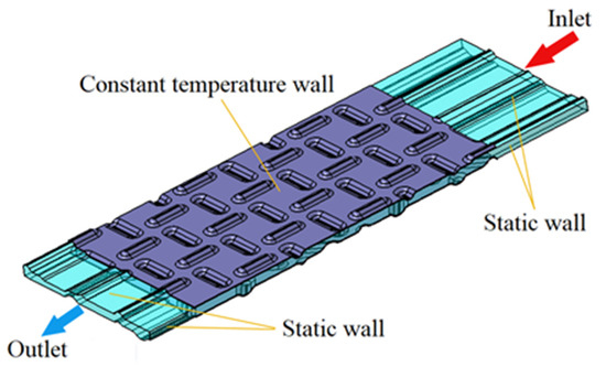
Figure 2.
Boundary conditions instruction.
3.2. Parameter Setting
The governing equation-solving algorithm should be determined for numerical calculation of the model. The SIMPLE algorithm is adopted to solve the coupling of pressure and velocity in fluid mechanics equations [31,32]. Table 2 shows the physical properties at the temperature of 363 K.
Table 2.
Physical properties of fluid and solid [33].
In order to give consideration to both simulation accuracy and calculation time, the solution domain is divided by Anasys mesh, and tetrahedral mesh was selected. In the grid independence verification, the computation time and results of seven different grid partitioning schemes are compared. The number of meshes of the seven schemes are 3.87 million, 4.39 million, 4.81 million, 5.32 million, 5.81 million, 6.36 million and 6.77 million. The simulation results are evaluated using Nusselt number. According to Nusselt number and calculation time, the optimal number of grids is evaluated comprehensively. As shown in Figure 3, as the number of grids increases, the calculation time is significantly prolonged, and the change in Nusselt number also tends to be stable. Therefore, 6.36 million grid units can meet the accuracy and time of calculation, as shown in Figure 4.
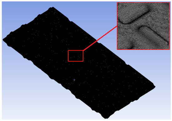
Figure 3.
The grid for entire computational domain.
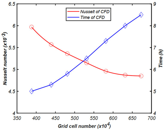
Figure 4.
Grid independence verification.
3.3. Comparison with the Experiment
In order to verify the credibility of the simulation results, the model is built according to the structural parameters in [22]. The data obtained through CFD calculation are compared with the results in the literature, as shown in Figure 5. Under the condition of RE = 3000 and RE = 9000, the Nu values of fluid simulation results and test results are compared. With the increase in turbulence, the variation trend of simulation and test is constant and Nu number increases. The coincidence between experimental and simulation data is higher than 90%. This comparison can confirm the accuracy of the simulation method and provide a credible basis for the follow-up research.
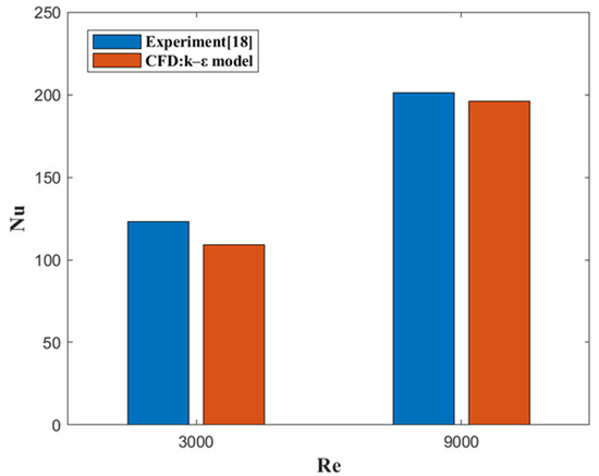
Figure 5.
Comparison of CFD result with experimental data [18].
4. Optimal Structure of Capsule-Type Plate
The capsule-type plate optimization problem of the heat exchanger is a multi-objective optimization problem. The optimization process is described as follows and the whole flow chart is shown in Figure 6.
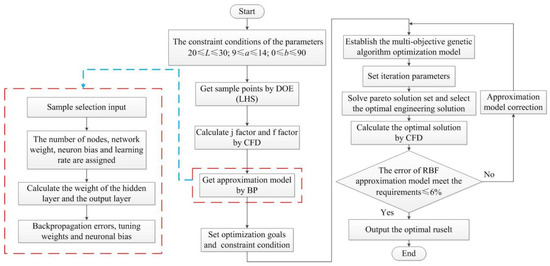
Figure 6.
Optimization process of capsule-type plate heat exchanger.
Step 1: constraint condition.
The purpose of plate heat exchangers shape optimization is to obtain high heat-transfer capability and low flow resistance. But the flow resistance and heat-transfer efficiency are contradictory conclusions. High heat-transfer performance usually requires a rough surface design, while low-resistance performance requires a smooth surface design. Due to these two conflicting objectives, the optimization of j/f is regarded as an optimization problem. j and f can be obtained as follows:
The variables in the above formula can be obtained by the nomenclature.
Because the design parameters are capsule length l, capsule angle a, capsule width b, the objective function can be defined as follows:
The structural parameters of the capsule plate are as follows [26]:
A higher heat transfer coefficient j usually means a higher friction coefficient f. However, in engineering applications, it is necessary to obtain a high heat transfer coefficient j, while friction coefficient f is as low as possible. The maximum j/f is selected as the objective function for optimization, which is defined as follows:
Max j/f = F(l,a,b)
Step 2: Design of experiments (DOE).
In this research, there is a nonlinear relationship between the three mechanism parameters, heat transfer factor j and friction factor f of heat exchanger performance. Therefore, experimental design methods of Latin Hypercube Sampling (LHS) are used to establish 50 groups of sample points. Colburn factor and friction factor are solved by CFD. LHS is the latest development in sampling techniques and is designed to accurately reconstruct the input distribution by sampling with fewer iterations. The key of LHS is to stratify the input probability distribution. The stratification divides the accumulation curve into equal intervals on the cumulative probability scale. The samples are then randomly drawn from each interval of the input distribution. The sampling is forced to represent the values of each interval and, thus, the input probability distribution is forced to be reconstructed.
Step 3: Approximation model.
In this paper, BP neural network is used to construct an approximation model. BP is a classical artificial neural network (ANN) training algorithm. By backpropagating the error signal, it adjusts the parameters of the network according to the gradient of the objective function to reduce the output error of the network so as to realize the purpose of learning and approximating any complex function. BP algorithm is a supervised learning algorithm, which requires a training data set as input, that is, input–output sample set. The nonlinear relationship between design variable and objective function is obtained by BP neural network, shown in Appendix B.
Step 4: Multi-objective optimization.
The MOGA is used to randomly generate an initial population. And each point is calculated. The optimal solution is determined according to constraints [26].
5. Optimal Result Analysis
After the above optimization process, l, a and b values of the optimal j/f capsule-type plate structure parameters were obtained, as shown in Table 3.
Table 3.
Structural parameters before and after optimization.
5.1. Physical Field Analysis
Figure 7, Figure 8 and Figure 9 show the flow field changes before and after capsule-type plate optimization. Figure 7 is the speed comparison diagram. The scattered capsule protrusions affect the fluid flow. As can be seen from the figure, a low-speed zone appears on the back flow surface of the capsule. At the same time, the phenomenon of flow around the region is generated and the fluid is turbulent.
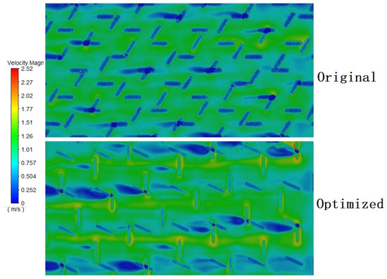
Figure 7.
The velocity comparison transverse section between the optimization and the original.
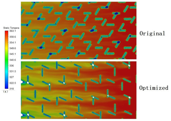
Figure 8.
The temperature comparison transverse section between the optimization and the original.
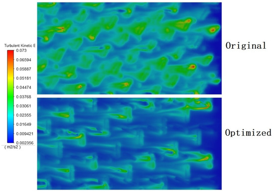
Figure 9.
The turbulent kinetic energy comparison transverse section between the optimization and the original.
After optimization, the layout angle of the bulge is changed so that the flow velocity through the plate is 11% higher. The higher flow rate in the runner is beneficial to the heat transfer of the plate. Figure 8 is the temperature comparison diagram. The results in the figure show that the temperature of the fluid decreases after flowing through the raised structure. After optimization, the temperature change of the plate is more obvious, and the temperature at the outlet is lower, increasing the temperature drop by 7.3%. Figure 9 is a comparison diagram of turbulence. It can be seen from the figure that the turbulent kinetic energy of the optimized plate is smaller. The optimized 3D model has a lower kinetic energy, which is reduced by 6%. At the same time, the reduced turbulent kinetic energy can reduce the pressure demand of fluid inflow. In terms of conjugate heat transfer, the optimized plate structure can be thermally coupled with the inflow better. When the fluid flows through the bulge, the turbulence formed can effectively improve the heat transfer effect and change the heat distribution of the heat exchange plate.
In conclusion, the optimized structure has higher flow rate, a larger temperature drop and smaller turbulent kinetic energy, and the performance of the optimized capsule-type plate heat exchanger has been improved. From the perspective of environmental sustainability, the processing difficulty of the optimized plate has not changed. But the heat transfer effect of the plate has been significantly improved. Compared with the original heat exchange plate, the optimized heat exchange plate can make the heat exchanger structure smaller and lighter with the same heat exchange efficiency. This also means optimized environmental sustainability benefits for heat exchangers.
5.2. The Field Synergy Analysis
In the study of convective heat transfer, the synergistic effect of fluid flow direction and temperature gradient plays a key role. The synergy between the two can be characterized by the synergy angle, as shown in Figure 10. The more co-operative the angle is conducive to heat transfer, the more reasonable the structure design. This paper introduces the synergy angle to evaluate the capsule-type plate. The synergy angle is defined as follows [31]:
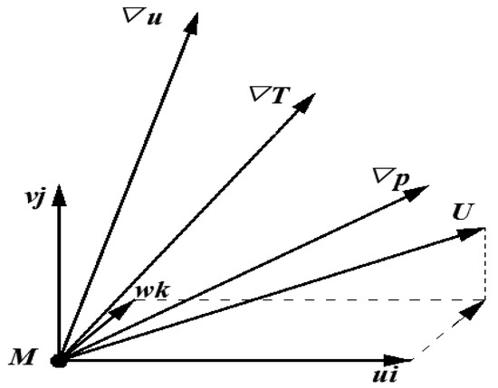
Figure 10.
Relationship between the physical qualities of particle M in the flow field.
5.2.1. Synergy Angle β
Figure 11 is a comparison of synergy angle β. It shows the ratio of velocity to temperature gradient of the flow field at the same position of the flow passage. According to the thermal principle, in the process of fluid flow along the flow channel, heat is continuously transmitted through the plate to the cold side, the temperature gradient is perpendicular to the flow direction, the synergy angle β is closer to 90° and the more conducive to the plate heat transfer, the higher the efficiency of the heat exchangers. By comparison, the optimized model has smaller β and better heat transfer performance.
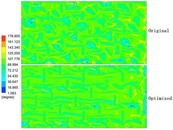
Figure 11.
Comparison of synergy angle β.
5.2.2. Synergy Angle θ
The comparison of the synergy angle θ is shown in Figure 12. It shows the ratio between velocity vector and pressure gradient of the flow field at the same position of the flow passage. It can be seen from the figure that synergy angle θ has similar characteristics before and after optimization, with higher values appearing in the bulge, because the bulge blocking causes the flow velocity to be opposite to the pressure direction. A higher synergy angle θ, on the other hand, indicates a higher inlet pressure for the fluid. Compared with the θ values before and after optimization, the optimized structure is smaller, which is beneficial to improve the heat transfer efficiency of the flow passage.
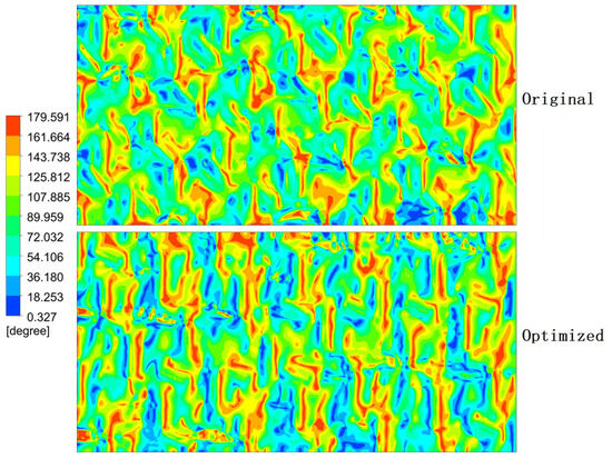
Figure 12.
Comparison of synergy angle θ.
5.2.3. Synergy Angle γ
Figure 13 below is a comparison of the synergy angle γ. It shows the ratio between the inflow velocity vector and the temperature gradient of the flow field at the same position in the flow passage. Larger γ indicates better overall heat transfer capacity. γ is obviously increased at the bulge, indicating that the bulge is an efficient area for heat exchange.
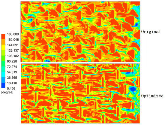
Figure 13.
Comparison of synergy angle γ.
6. Conclusions
In this study, a new capsule-type plate heat exchanger is used to optimize the plate structure by CFD, LHS, BP and MOGA. After optimization, the heat transfer coefficient is increased by 8.3% and the friction coefficient is decreased by 14.3% within the model size range. The heat transfer effect is obviously improved. At the same time, the velocity, temperature and turbulent kinetic energy are also optimized. The field co-ordination number is further analyzed. All in all, the optimized heat exchanger has better performance and can meet higher work requirements. The method proposed in this paper combines enhanced heat transfer theory and optimization theory. Using simulations rather than expensive and time-consuming experiments to obtain desirable structural parameters. It can provide a technical basis for the design of high-performance heat exchangers.
Author Contributions
Conceptualization, C.Y.; methodology, M.S.; software, W.Z.; validation, G.W.; formal analysis, M.H. All authors have read and agreed to the published version of the manuscript.
Funding
This research received no external funding.
Data Availability Statement
The data can be obtained by contacting the author via email.
Conflicts of Interest
The authors declare no conflicts of interest.
Nomenclature
| l | capsule length (mm) | ci | center of clustering |
| a | capsule angle ) | ∇T | temperature gradient (K/m) |
| b | capsule width (mm) | ∇p | pressure gradient (Pa/m) |
| t | capsule plate thickness (mm) | ∇u | velocity gradient (1/s) |
| j | Heat transfer factor | ||
| f | friction factor | Re | Reynolds number |
| T | temperature (K) | Pr | Prandtl number |
| D | hydraulic diameter (m) | Nu | Nusselt number |
| ΔP | pressure difference (Pa) | ||
| m | mass flow (kg/s) | ρ | density (kg/m3) |
| cp | constant-pressure specific heat (J/(kg °C)) | μ | dynamic viscosity (N s/m2) |
| w | weight | λt | thermal conductivity (W/(m °C)) |
| n | number of samples | σ | variance of basis function |
| ui, vj, wk | velocity component in co-ordinate system (m/s) | ||
Appendix A
| 50 sets of Structural Parameter Sample Points | |||||||
| Num | l (mm) | a (°) | b (mm) | Num | l (mm) | a (°) | b (mm) |
| 1 | 26 | 5 | 12.2 | 26 | 25 | 43 | 13 |
| 2 | 21 | 12 | 9.8 | 27 | 24 | 74 | 13.7 |
| 3 | 30 | 49 | 13.7 | 28 | 27 | 61 | 10.5 |
| 4 | 29 | 72 | 11.5 | 29 | 29 | 51 | 12.9 |
| 5 | 26 | 47 | 13.9 | 30 | 23 | 26 | 9.6 |
| 6 | 22 | 41 | 11.3 | 31 | 25 | 65 | 12.7 |
| 7 | 22 | 68 | 9.8 | 32 | 24 | 22 | 12.1 |
| 8 | 20 | 38 | 10.7 | 33 | 21 | 4 | 9.1 |
| 9 | 30 | 84 | 11.5 | 34 | 26 | 15 | 11.4 |
| 10 | 29 | 30 | 10.1 | 35 | 28 | 17 | 9.5 |
| 11 | 20 | 57 | 11 | 36 | 21 | 33 | 11.9 |
| 12 | 20 | 38 | 9.3 | 37 | 23 | 9 | 11.7 |
| 13 | 26 | 44 | 13.3 | 38 | 28 | 52 | 10.1 |
| 14 | 23 | 61 | 13.1 | 39 | 25 | 1 | 10.5 |
| 15 | 24 | 19 | 10.8 | 40 | 28 | 77 | 12.5 |
| 16 | 26 | 28 | 13.1 | 41 | 22 | 31 | 12.3 |
| 17 | 24 | 21 | 11.8 | 42 | 28 | 7 | 14 |
| 18 | 23 | 55 | 9.1 | 43 | 27 | 82 | 13.4 |
| 19 | 25 | 59 | 10.2 | 44 | 29 | 46 | 12.6 |
| 20 | 22 | 13 | 11.2 | 45 | 23 | 63 | 10.3 |
| 21 | 20 | 85 | 12.7 | 46 | 22 | 90 | 12.2 |
| 22 | 21 | 69 | 11.8 | 47 | 27 | 7 | 10.9 |
| 23 | 21 | 75 | 9.7 | 48 | 27 | 87 | 10.7 |
| 24 | 24 | 24 | 10 | 49 | 21 | 35 | 13.5 |
| 25 | 25 | 80 | 13.2 | 50 | 20 | 77 | 9.3 |
Appendix B. Nonlinear Relationship between Parameters and Performances

References
- Arsenyeva, O.; Tran, J.; Piper, M.; Kenig, E. An approach for pillow plate heat exchangers design for single-phase applications. Appl. Therm. Eng. 2019, 147, 579–591. [Google Scholar] [CrossRef]
- Arsenyeva, O.; Piper, M.; Zibart, A.; Olenberg, A.; Kenig, E.Y. Investigation of heat transfer and hydraulic resistance in small-scale pillow-plate heat exchangers. Energy 2019, 181, 1213–1224. [Google Scholar] [CrossRef]
- Piper, M.; Olenberg, A.; Tran, J.M.; Kenig, E.Y. Determination of the geometric design parameters of pillow-plate heat exchangers. Appl. Therm. Eng. 2015, 91, 1168–1175. [Google Scholar] [CrossRef]
- Piper, M.; Zibart, A.; Djakow, E.; Springer, R.; Homberg, W.; Kenig, E.Y. Heat transfer enhancement in pillow-plate heat exchangers with dimpled surfaces: A numerical study. Appl. Therm. Eng. 2019, 153, 142–146. [Google Scholar] [CrossRef]
- Piper, M.; Zibart, A.; Kenig, E.Y. New design equations for turbulent forced convection heat transfer and pressure loss in pillow-plate channels. Int. J. Therm. Sci. 2017, 120, 459–468. [Google Scholar] [CrossRef]
- Piper, M.; Zibart, A.; Tran, J.M.; Kenig, E.Y. Numerical investigation of turbulent forced convection heat transfer in pillow plates. Int. J. Heat Mass Transf. 2016, 94, 516–527. [Google Scholar] [CrossRef]
- Tran, J.M.; Piper, M.; Kenig, E.Y. Experimental Investigation of Convective Heat Transfer and Pressure Drop in Pillow Plates under Single-Phase Through-Flow Conditions. Chem. Ing. Tech. 2015, 87, 226–234. [Google Scholar] [CrossRef]
- Tran, J.M.; Sommerfeld, S.; Piper, M.; Kenig, E.Y. Investigation of pillow-plate condensers for the application in distillation columns. Chem. Eng. Res. Des. 2015, 99, 67–74. [Google Scholar] [CrossRef]
- Shirzad, M.; Ajarostaghi, S.S.M.; Delavar, M.A.; Sedighi, K. Improve the thermal performance of the pillow plate heat exchanger by using nanofluid: Numerical simulation. Adv. Powder Technol. 2019, 30, 1356–1365. [Google Scholar] [CrossRef]
- Song, J.; Wang, F.; Cheng, L. Experimental study and analysis of a novel multi-media plate heat exchanger. Sci. China-Technol. Sci. 2012, 55, 2157–2162. [Google Scholar] [CrossRef]
- Pei, B.; Chen, Z.; Li, F.; Bai, B. Flow and heat transfer of supercritical CO2 in the honeycomb ultra-compact plate heat exchanger. J. Supercrit. Fluids 2019, 148, 1–8. [Google Scholar] [CrossRef]
- Wenjing, D.U.; Wang, F.; Zhang, S.H.; Gao, X.D.; Cheng, L. Thermodynamic Analysis on The Regular Hexagonal Plate Heat Exchanger. J. Eng. Thermophys. 2010, 31, 1763–1766. [Google Scholar]
- Jamzad, P.; Kenna, J.; Bahrami, M. Development of novel plate heat exchanger using natural graphite sheet. Int. J. Heat Mass Transf. 2019, 131, 1205–1210. [Google Scholar] [CrossRef]
- Durmus, A.; Benli, H.; Kurtbas, I.; Gul, H. Investigation of heat transfer and pressure drop in plate heat exchangers having different surface profiles. Int. J. Heat Mass Transf. 2009, 52, 1451–1457. [Google Scholar] [CrossRef]
- Zhang, C.; Wang, D.; Han, Y.; Zhu, Y.; Peng, X. Experimental and numerical investigation on the exergy and entransy performance of a novel plate heat exchanger. Exp. Heat Transf. 2017, 30, 162–177. [Google Scholar] [CrossRef]
- Jeong, J.Y.; Hong Hk Kim, S.K.; Kang, Y.T. Impact of plate design on the performance of welded type plate heat exchangers for sorption cycles. Int. J. Refrig. 2009, 32, 705–711. [Google Scholar] [CrossRef]
- Jiang, C.; Bai, B.F. Flow patterns and pressure drop of downward two-phase flow in a capsule-type plate heat exchanger. Exp. Therm. Fluid Sci. 2019, 103, 347–354. [Google Scholar] [CrossRef]
- Zhang, Y.; Jiang, C.; Yang, Z.; Zhang, Y.; Bai, B. Numerical study on heat transfer enhancement in capsule-type plate heat exchangers. Appl. Therm. Eng. 2016, 108, 1237–1242. [Google Scholar] [CrossRef]
- Alqutub, A.M.; Linjawi, M.T.; Alrawi, I.M. Performance Study of a Dimpled-Protruded Air-to-Air Plate Heat Exchanger. In Proceedings of the International Conference on ASME Power Conference Collocated with the ASME International Conference on Energy Sustainability, San Diego, CA, USA, 28 June–2 July 2015. [Google Scholar]
- Kim, M.; Baik, Y.-J.; Park, S.-R.; Ra, H.-S.; Lim, H. Experimental study on corrugated cross-flow air-cooled plate heat exchangers. Exp. Therm. Fluid Sci. 2010, 34, 1265–1272. [Google Scholar] [CrossRef]
- Doo, J.H.; Ha, M.Y.; Min, J.K.; Stieger, R.; Rolt, A.; Son, C. An investigation of cross-corrugated heat exchanger primary surfaces for advanced intercooled-cycle aero engines (Part-I: Novel geometry of primary surface). Int. J. Heat Mass Transf. 2012, 55, 5256–5267. [Google Scholar] [CrossRef]
- Lee, J.M.; Kwan, P.W.; Son, C.M.; Ha, M.Y. Characterizations of aerothermal performance of novel cross-corrugated plate heat exchangers for advanced cycle aero-engines. Int. J. Heat Mass Transf. 2015, 85, 166–180. [Google Scholar] [CrossRef]
- Kanaris, A.G.; Mouza, A.A.; Paras, S.V. Optimal design of a plate heat exchanger with undulated surfaces. Int. J. Therm. Sci. 2009, 48, 1184–1195. [Google Scholar] [CrossRef]
- Imran, M.; Pambudi, N.A.; Farooq, M. Thermal and hydraulic optimization of plate heat exchanger using multi objective genetic algorithm. Case Stud. Therm. Eng. 2017, 10, 570–578. [Google Scholar] [CrossRef]
- Giurgiu, O.; Pleşa, A.; Socaciu, L. Plate Heat Exchangers—Flow Analysis through Mini Channels. Energy Procedia 2016, 85, 244–251. [Google Scholar] [CrossRef][Green Version]
- Jin, S.; Hrnjak, P. Effect of end plates on heat transfer of plate heat exchanger. Int. J. Heat Mass Transf. 2017, 108, 740–748. [Google Scholar] [CrossRef]
- Longo, G.A.; Gasparella, A.; Sartori, R. Experimental heat transfer coefficients during refrigerant vaporisation and condensation inside herringbone-type plate heat exchangers with enhanced surfaces. Int. J. Heat Mass Transf. 2004, 47, 4125–4136. [Google Scholar] [CrossRef]
- Hu, S.; Ma, X.; Zhou, W. Condensation heat transfer of ethanol-water vapor in a plate heat exchanger. Appl. Therm. Eng. 2017, 113, 1047–1055. [Google Scholar] [CrossRef]
- Yu, C.; Xue, X.; Shi, K.; Shao, M. A Three-Dimensional Numerical and Multi-Objective Optimal Design of Wavy Plate-Fins Heat Exchangers. Processes 2021, 9, 9. [Google Scholar] [CrossRef]
- Khodabandeh, E.; Toghraie, D.; Chamkha, A.; Mashayekhi, R.; Akbari, O.; Rozati, S.A. Energy saving with using of elliptic pillows in turbulent flow of two-phase water-silver nanofluid in a spiral heat exchanger. Int. J. Numer. Methods Heat Fluid Flow 2020, 30, 2025–2049. [Google Scholar] [CrossRef]
- Hwang, S.D.; Kwon, H.G.; Cho, H.H. Local Heat Transfer and Thermal Performance on Periodically Dimple-protrusion Patterned Walls for Compact Heat Exchangers. Energy 2010, 35, 5357–5364. [Google Scholar] [CrossRef]
- Yu, C.; Xue, X.; Shi, K.; Wang, R.; Zhang, L. Optimization of wavy fin-and-elliptical tube heat exchanger using CFD, multi-objective genetic algorithm and radical basis function. Energy Sci. Eng. 2021, 9, 1359–1372. [Google Scholar] [CrossRef]
- Li, P.P. Research on Performance of the Plate Oil Radiator for Construction Vehicle. Doctoral Dissertation, Jilin University, Changchun, Jilin, 2016. Available online: https://xueshu.baidu.com/usercenter/paper/show?paperid=1fabe1d7768e0820f565bb672e9b17d5&site=xueshu_se (accessed on 1 January 2024).


Disclaimer/Publisher’s Note: The statements, opinions and data contained in all publications are solely those of the individual author(s) and contributor(s) and not of MDPI and/or the editor(s). MDPI and/or the editor(s) disclaim responsibility for any injury to people or property resulting from any ideas, methods, instructions or products referred to in the content. |
© 2024 by the authors. Licensee MDPI, Basel, Switzerland. This article is an open access article distributed under the terms and conditions of the Creative Commons Attribution (CC BY) license (https://creativecommons.org/licenses/by/4.0/).