
Research on the Performance Characteristics of a Waste Heat Recovery Compound System for Series Hybrid Electric Vehicles

State Key Laboratory of Automotive Simulation and Control, Jilin University, Changchun 130025, China
*
Author to whom correspondence should be addressed.
Processes 2024, 12(3), 605; https://doi.org/10.3390/pr12030605
Submission received: 25 February 2024
/
Revised: 8 March 2024
/
Accepted: 11 March 2024
/
Published: 18 March 2024
(This article belongs to the Special Issue Advanced Thermodynamic Analysis of Chemical Systems)
Abstract
:In this paper, a waste heat recovery compound system for series hybrid electric vehicles is established. The existing components of vehicle air conditioning are used in the organic Rankine cycle (ORC) to realize miniaturization. The waste heat recovery compound system is constructed using GT-SUITE, and the objective of the analysis is to increase the power output and engine thermal efficiency increase ratio (ETEIR). The effects of the expander speed, pump speed, working fluid mass flow rate, and working fluid type on the waste heat recovery compound system are analyzed. The simulation results show that the optimal schemes for the ORC system and compound system corresponding to the expander speed and pump speed are 1000 pm, 2500 rpm, 1200 rpm, and 2500 rpm, respectively. Compared with the ORC system, the maximum power output of the compound system with the same working fluid in three states (1500 rpm, 2500 rpm, and 3500 rpm) of the engine is increased by 21.67%, 24.05%, and 28.23%, respectively. Working fluid supplies of 0.4 kg/s, 0.4 kg/s, and 0.6 kg/s in the three engine states are also considered the best solutions. The working fluid R1234yf and R1234ze are the preferred choices for a waste heat recovery compound system, which have a high system power output and ETEIR and are environmentally friendly.
1. Introduction
Energy and environmental problems urgently require the development of energy-saving and environmentally friendly vehicles [1], and hybrid electric vehicles (HEVs) are an effective energy conservation and environmental protection strategy [2]. Through the collaborative work of the engine and an electric motor, HEVs can achieve excellent comprehensive performance [3]. In most hybrid vehicles, the internal combustion engine (ICE) still plays an important role. Currently, the efficiency of primary energy being converted into the mechanical power of the ICE is low [4], and the thermal energy carried by the automobile exhaust accounts for about 40% of the fuel consumption [5]. The recovery of energy from the automobile exhaust can improve the power output and thermal efficiency of an ICE [6]. The waste heat recovery (WHR) and utilization of the ICE are of great significance to the global demand for energy conservation and emission reduction [7]. There are mainly two kinds of WHR technologies applied in automobiles: one is thermoelectric conversion (TEG) and TEG combined with heat pipes; the second is the organic Rankine cycle (ORC). The principle of thermoelectric conversion is the realization of the Seebeck effect. In thermoelectric power generation, when there is a temperature difference between the upper and lower ends of the semiconductor, a voltage will be generated. In the design of TEG, a higher conversion efficiency can be achieved by combining heat pipes. It uses low-boiling organic matter as a working medium to absorb the waste heat energy. After evaporation and gasification, it enters the expander for mechanical purposes. This mechanical work can drive the generator to generate electricity or can be superimposed onto the engine crankshaft using a transmission device. The ORC has significant advantages in recovering low-grade energy [8] and has been used in many fields [9]. However, the ICE operating condition range is very wide and often transient. In most cases, variability and transient operating conditions lead to the ICE being far from its ideal operating point. HEVs can make the engine work in an ideal range [10], effectively improving their fuel efficiency [11].
In the research on the WHR and utilization of hybrid vehicles, some scholars directly convert waste thermal energy into electrical energy of TEG [12]. Smith et al. [13] considered three HEV platforms, and a steady-state model predicted that 5% and 10% of the engine waste thermal energy could be recovered using the TEG system, respectively. Wang et al. [14] proposed a refined vehicle mode conversion strategy, and the results showed that the mode conversion strategy could improve the engine efficiency and average exhaust temperature. Vijayagopal et al. [15] improved the WHR by introducing a heat reservoir into the TEG model and determined the technology and threshold that may prevent TEG from becoming an acceptable means of automobile WHR. Fang et al. [16] proposed an integrated starter generator (ISG) HEV scheme, and the data analysis showed the superiority of the proposed integrated scheme and a reduction in the power consumption under the European driving cycle (EDC). Deng et al. [17] developed an electric and hybrid drive system with a 42 V power grid and an ISG. The system can achieve dual optimization of fuel economy and exhaust emissions and has better acceleration performance. When TEG is applied to an HEV, the torque separation control strategy is more advantageous than the electric assist control strategy. However, this technology is limited by its low conversion efficiency, so it has not been widely used. This limitation is reflected in the hot-end temperature limiting the selection of materials for thermoelectric conversion. Thus, materials are one of the main constraints of TEG technology. The combined use of heat pipes and TEG helps reach a TEG surface temperature closer to gas temperature and can also prevent TEG overheating when the TEG hot-end temperature is too high. However, the conversion efficiency is still low.
ORC is the most efficient and potentially industrial form of the existing WHR technologies. Thus far, many scholars have investigated ORC systems. Shu et al. [18] proposed an ORC system with hot oil storage, and the simulation results showed that the heat conduction oil positively impacts the change in the engine conditions. Zhang et al. [19] proposed a compound cycle system with a maximum recovery power of 13 kW. Konstantinos et al. [20] investigated an integrated thermal–economic optimization method for standard and regenerative ORC with significant economic effects. Another obvious advantage of the ORC’s application in ICEs is that the specific emissions are reduced through an additional power output without extra fuel [21]. The ORC system improves the thermal efficiency [22,23,24], the power output [25,26,27], the engine efficiency [28,29], and the system efficiency [30]. However, its commercial application is hampered by the compactness and economy of the vehicle [31]. The use of existing components of vehicles for the ORC provides an opportunity for improvement [32].
Compared with traditional vehicles, the main challenge and limitation of WHR for HEVs are the intermittent operation of the engine and the low total waste heat. A series hybrid electric vehicle (SHEV) is a special type of hybrid vehicle that works by providing power through a series combination of an internal combustion engine and an electric motor. In this configuration, the ICE does not drive the wheels directly but instead acts as a generator, providing electricity to the electric motor or charging the battery. Longer running times and the higher total exhaust energy of the SHEV make it more suitable for integration with the ORC system. On such a basis, a waste heat recovery compound system (WHRCS) for a SHEV is established in this paper, which integrates WHR and air conditioning (AC) refrigeration functions. The condenser and pump/compressor in the AC cycle are used in the ORC cycle to realize miniaturization. The system model is constructed using GT-SUITE, and the effects of the expander speed, pump speed, working fluid (WF) mass flow rate, and WF type on the WHRCS are analyzed. The innovation of this research is the recovery of waste heat from a SHEV within the fixed engine operating conditions and realizing miniaturization by combining WHR with the AC system.
2. Methodology and Assumption
2.1. System Description
A WHRCS can operate in three modes, AC cycle mode (ACCM), ORC mode (ORCM), and compound cycle mode (CCM), which are shown in Figure 1, where the condenser and pump/compressor in the AC cycle are added to the ORC cycle to realize miniaturization. The system operates in ACCM when cabin refrigeration is required (Figure 1a); in ORCM when WHR is required (Figure 1b); and in CCM when both refrigeration and WHR are required (Figure 1c). The operating mode is switched by activating and deactivating six automatic valves.
In Figure 1, symbol 1 (engine) mainly supplies energy to the generator and provides high-temperature exhaust gas (EG) for the WHR system; symbol 2 (exhaust gas bypass valve) controls whether the exhaust gas enters the WHR system; symbol 3 (WHR evaporator) heats the WF to a high temperature and a high-pressure vapor state; symbol 5 (expander) can convert thermal energy into mechanical energy; symbol 7 (condenser) cools the WF to a liquid state; symbol 8 (liquid storage tank) is for filtering; the function of symbol 9 (expansion valve) is to atomize the WF; symbol 10 (air conditioning evaporator) vaporizes the WF at a low temperature and low pressure; symbol 11 (air blower) blows cold air into the cab; symbol 12 acts as the AC cycle for the compressor, which pressurizes the WF; and in the ORC cycle and compound cycle is the pump, which adiabatically compresses the WF. Symbol s4, 6, 13, 14, and 15 are the valves, which control the flow of the WF.
First, the drive section needs to calculate the power required to follow the drive cycle, which is passed to the traction motors to move the vehicle. Then, with reference to the real-time state of charge (SOC) of the battery, the ICE–generator combination charges the battery. The ICE–generator set has four working states, as shown in Figure 2. When the battery SOC ≥ 75%, it is in state 1. The engine does not operate, and the battery discharges to drive the vehicle. When the battery SOC ≤ 65%, it is in state 2. The engine runs at 1500 rpm, and the battery is continuously charged while driving the vehicle. When the battery SOC ≤ 50%, it is in state 3. The engine runs at 2500 rpm, and the battery is continuously charged while driving the vehicle. When the battery SOC ≤ 35%, it is in state 4. The engine runs at 3500 rpm, and the battery is continuously charged while driving the vehicle.
The vehicle operation mode is first determined when the vehicle is in operation. The vehicle is in the energy recovery mode when it is downhill or decelerated, the engine and ORC system do not work, and the motor charges the battery. If the battery SOC ≥ 75%, the vehicle is in purely electric mode, the engine and ORC system do not operate, and the power is entirely provided by the battery. If the battery SOC ≤ 75%, the vehicle will be converted into hybrid power mode, and the motor works and drives the vehicle forward. If the power of the motor driving the vehicle is less than the power of the engine operation, the battery behaves charges; otherwise, the battery discharges. When the battery SOC is below a specific limit, the engine boosts the output power, and the battery continues to charge while driving the vehicle.
The vehicle is in hybrid power mode when the engine is in a cold start and idle stage, and due to the low energy of the exhaust gas, the recovery operation is not carried out. When the WHR is not operating, valve 4, valve 6 and valve 13 are closed. If AC refrigeration is required, valve 14 is opened, and the system works as an ACCM. Once the EG energy is sufficient to be recovered, WHR will run automatically. If AC refrigeration is not required, valve 9 is closed, and AC valve 15 is opened. At this time, the system works in ORCM. If AC refrigeration is required, the system works in CCM. When the energy is insufficient, valve 13 is closed, and valve 14 is opened to stop the WHR. In addition, the power from the expander is used to generate electricity to charge the battery. In pure electric mode and energy recovery mode, if AC refrigeration is needed, the starting method of the AC cycle system is the same as the above.
2.2. The SHEV Model
A SHEV is a medium-sized vehicle with a 120 kW 2.0 L spark ignition (SI) V4 engine and a total weight of 1600 kg. The related parameters of the SHEV are shown in Table 1. The motor drives the vehicle forward, and it can be used as a traction motor when driving or as a generator when braking. The power of the expander in the ORC/compound cycle is used to generate electricity to charge the battery.
The power balance equation is given as follows:
2.3. Performance Indicators
For AC cycle systems, the coefficient of performance (COP) can be calculated using Equation (3):
For ORC systems, the net power output can be calculated using Equation (4):
For the compound cycle system, the net power output can be calculated using Equation (5):
For the ORC system and the compound cycle system, the engine thermal efficiency increase ratio (ETEIR) can be calculated using Equation (6):
2.4. Model Verification
In the process of building the model, we mainly use the thermodynamics, fluid dynamics, and control system modules in GT-SUITE, which can help us accurately simulate the heat transfer, fluid flow, and control strategy in the system. Specifically, we used GT-POWER to simulate the working process of the engine and to evaluate the generation and availability of waste heat. At the same time, we use GT-COOL to simulate the WHR performance to determine the recovery power.
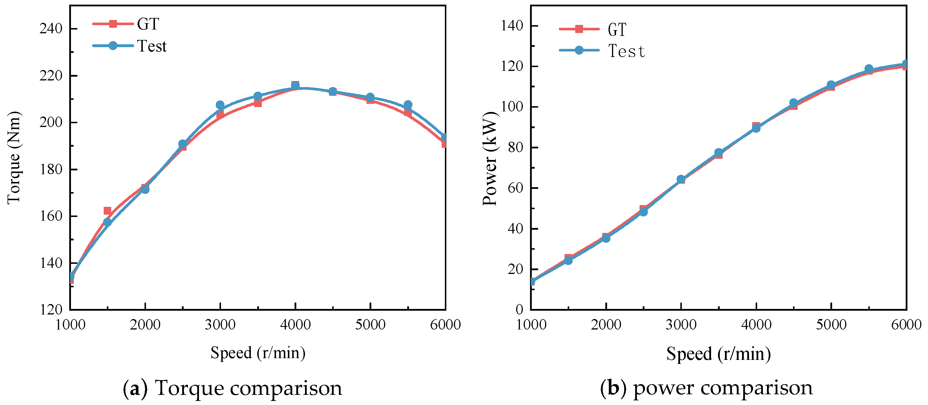
The feasibility of the model should be verified first before applying the model to performing several simulation experiments. GT-SUITE v2023 software is used to simulate and analyze the model of the 2.0 T GDI gasoline engine, and the operating points of the external characteristics of the gasoline engine test are used for the simulation calculations. A physical image of the experimental bench is shown in Figure 3.
The comparison results for the torque and power curves obtained using the simulation and the extra-experimental characteristic data are shown in Figure 4. It can be seen from Figure 4 that the simulation model is consistent with the actual bench test data, and the error is within 3%, which is within the allowable error range for engineering calculations.
The EG mass flow and exhaust temperature parameters of the simulation model are set according to the experimental results. To obtain the parameters of the engine EG, experiments are carried out according to the operating conditions of the gasoline engine at different speeds under full load. Table 2 shows the output power, EG temperature, exhaust mass flow rate, and other parameters at different engine speeds under a full load. It can be seen from Table 1 that under a full load, the EG temperature of the engine at different speeds is above 600 °C, which can meet the working conditions of the Rankine cycle.
To verify the models constructed using GT-SUITEs for a WHRCS, the results are compared with the existing research. Table 3 shows the comparison results. These results are only used as a reference, and the reason for the differences may be the combined effect of multiple factors.
According to the data in Table 3, it can be seen that compared with the results published previously, the model in this study has certain advantages in terms of the AC system and the ORC system; especially, the range of the output power of the ORC system is much higher than the values in the references. The output power of the compound system in this study differs significantly from that of the references, but the difference in the ETEIR is not significant. The main reason is that the engine in the references is a diesel engine, while the engine in this study is a gasoline engine. The different operating conditions and loads of the two engines result in the different engine output powers, different exhaust gas temperatures, and different exhaust gas flow rates provided. There is a big difference between the output power of the compound system and the reference, but there is little difference in the ETEIR. The main reason for this result is that the engine in the reference is a diesel engine, and the engine in this study is a gasoline engine. The different working conditions and loads of the two engines lead to different engine output powers, and the exhaust gas temperature and exhaust gas flow provided are also different.
3. Results and Analysis
3.1. Sensitivity Analysis of the Expander Speed and Pump Speed
The expander speed and pump speed are both influencing factors for the system’s power output and ETEIR. The engine of the SHEV only runs in three states (1500 rpm, 2500 rpm, and 3500 rpm), and the corresponding exhaust flow rates of the three states are 0.043 kg/s, 0.15 kg/s, and 0.23 kg/s, respectively. Refrigerant R134 A is an organic fluid with a low global warming potential (GWP) and relatively good environmental performance, which is widely used in refrigeration and air conditioning systems. Figure 5 and Figure 6 summarize the steady-state point of the simulation results of a set of ORC systems with a 0.6 kg/s supply of R134a and tests the heat utilization effect of the ORC systems with different expander speeds and pump speeds under three engine operating states. The parametric research ranges for the expander speed and pump speed are 800–2000 rpm and 1000–3000 rpm, respectively. Obviously, the power output of the ORC system increases first and then decreases with an increased expander speed, and it does not change after the pump speed increases to a specific value. This is because the rise in the expander speed and pump speed can generate more power. However, if the expander speed is too high, its power consumption will increase, and the power output will decrease.
When the pump speed increases to a certain value, the output power does not change. This is because the pump speed increases at this time; although the WF can carry more energy, the mechanical loss will be obvious. The maximum power output of the ORC system corresponds to an expander speed of 1000 rpm and a pump speed of 2500 rpm. Overall, the pump speed impacts the system output power more than the expander speed. This is mainly because the pump relies on the centrifugal force generated by the high-speed rotating impeller to transport the liquid. The kinetic energy is converted into static pressure energy, and the WF reaches a higher pressure. The pressure of the WF will directly affect the pressure drop in the WF in the adiabatic expansion process in the expander, which affects the system’s power output. In addition, the operating state of the engine has a more direct impact on the power output of the system, and the system’s power output increases with the increase in engine speed. An increase in engine speed is accompanied by an increase in the EG mass flow rate, which converts more exhaust thermal energy into mechanical energy. The ETEIR shows the same trend as the system power output. An expander speed of 1000 rpm and a pump speed of 2500 rpm can be regarded as the best solution. The system’s power output and ETEIR reached 0.775 kW, 1.852 kW, and 2.993 kW and 3.47%, 3.73%, and 4.23%, respectively.
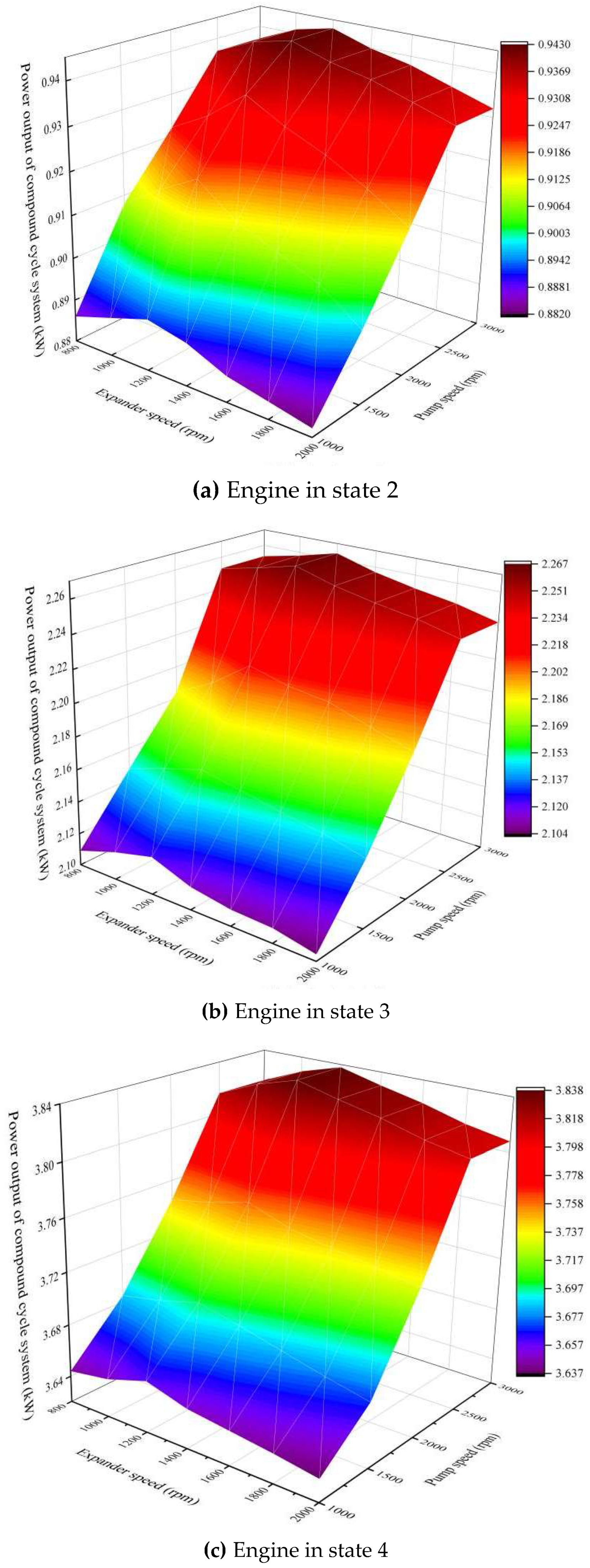
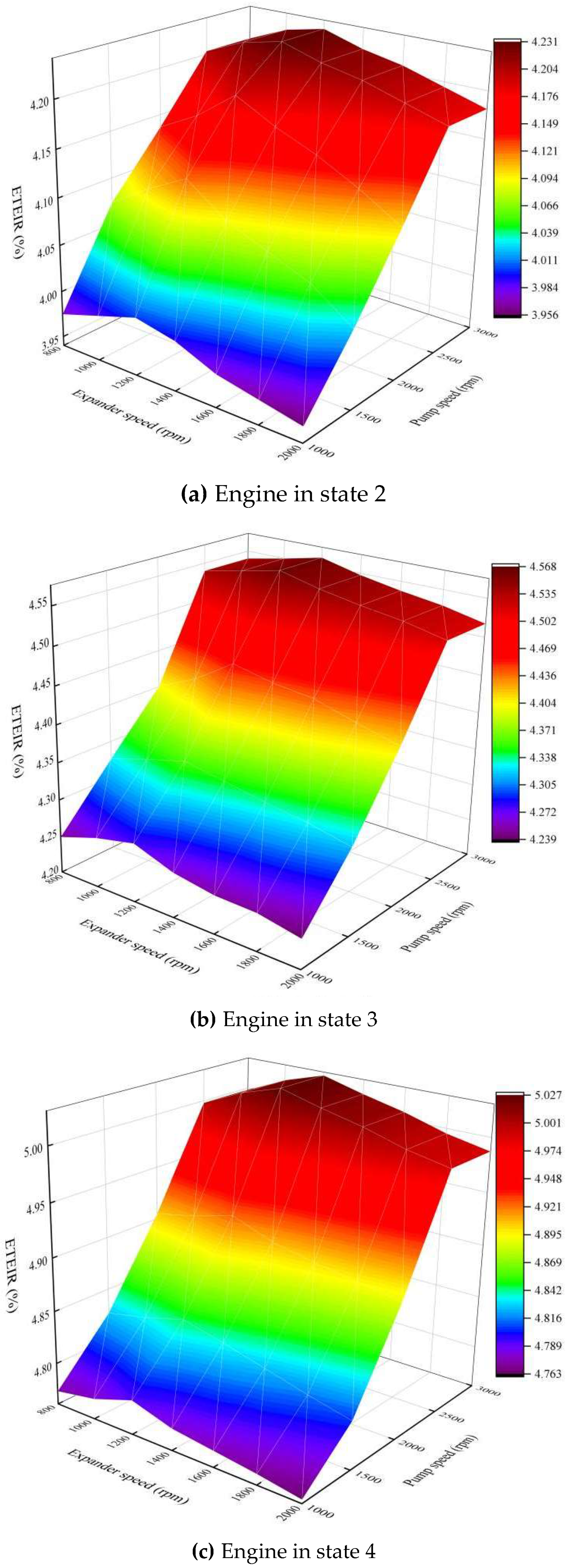
Figure 7 and Figure 8 show the results of the compound cycle system using R134a, which is similar to the ORC system. However, in fact, it can be seen from the results that the output power of CCM is more significant than that of the ORC system. Under the three engine states, the expander speed and pump speed corresponding to the maximum power output of the compound cycle system are 1200 rpm and 2500 rpm, respectively. Compared with the ORC system, the speed of the expander corresponding to the maximum power output of the compound cycle system increases because the WF expands in the expander and drives the impeller to rotate to generate the external output. And the greater the external power output of the system is, the higher the speed is. The compound cycle system power output and the ETEIR of the optimal solution reach 0.943 kW, 2.264 kW, and 3.838 kW and 4.23%, 4.56%, and 5.02%, respectively. Compared with the optimal solution for the ORC system, the maximum power output of the compound cycle system in the three states of the engine is increased by 21.67%, 24.05%, and 28.23%, respectively. These indicators represent the better performance of the compound cycle system than that of the ORC system.
3.2. Sensitivity Analysis of the WF Mass Flow Rate
As mentioned above, the system’s power output and the ETEIR increase and then decrease with the expander speed and pump speed at the same EG mass flow rate. However, whether increasing the mass flow rate of the WF has limitations in improving the system’s power output and the ETEIR needs to be discussed. This section evaluates supply strategies for the following WF mass flow rates. The parametric range for the mass flow rate of R134a in the research is 0.2–1.0 kg/s. The sensitivity of the expander and pump speeds has been discussed in Section 3.1. The optimal solution is selected, and R134a is supplied to the system at different mass flow rates, where the evaporator area is determined. Comparisons of different mass flow rates of R134a are shown in Figure 9 and Figure 10.
The results show that the mass flow rate has little effect at low and medium engine speeds (1500 rpm and 2500 rpm). At a high engine speed (3500 rpm), the sensitivity of the mass flow rate is enhanced. The system’s power output to the ETEIR shows the same trend, and the change in the ETEIR is more prominent. Overall, the power output and the ETEIR of the ORC and compound cycle systems increased initially and then decreased with an increasing WF mass flow rate. There is still an optimum WF supply mass flow rate to enhance the system’s power output and ETEIR. More fluid enhances the heat transfer with an increase in the WF mass flow rate to generate more power. However, if the mass flow rate of MF is large, the friction loss in the parts and pipes will be obvious, so the power output will be reduced. At low and medium engine speeds (1500 rpm and 2500 rpm), R134a is supplied at 0.4 kg/s, and at high engine speeds (3500 rpm), R134a is supplied at 0.6 kg/s as the optimal scheme. The power output and ETEIR of the ORC system and the compound cycle system in the optimal strategy under the three engine operating states are 0.782 kW, 1.857 kW, 2.993 kW and 3.5%, 3.74%, 3.92% and 0.947 kW, 2.269 kW, 3.838 kW and 4.24%, 4.57%, 5.02%, respectively.
3.3. Working Fluid Selection
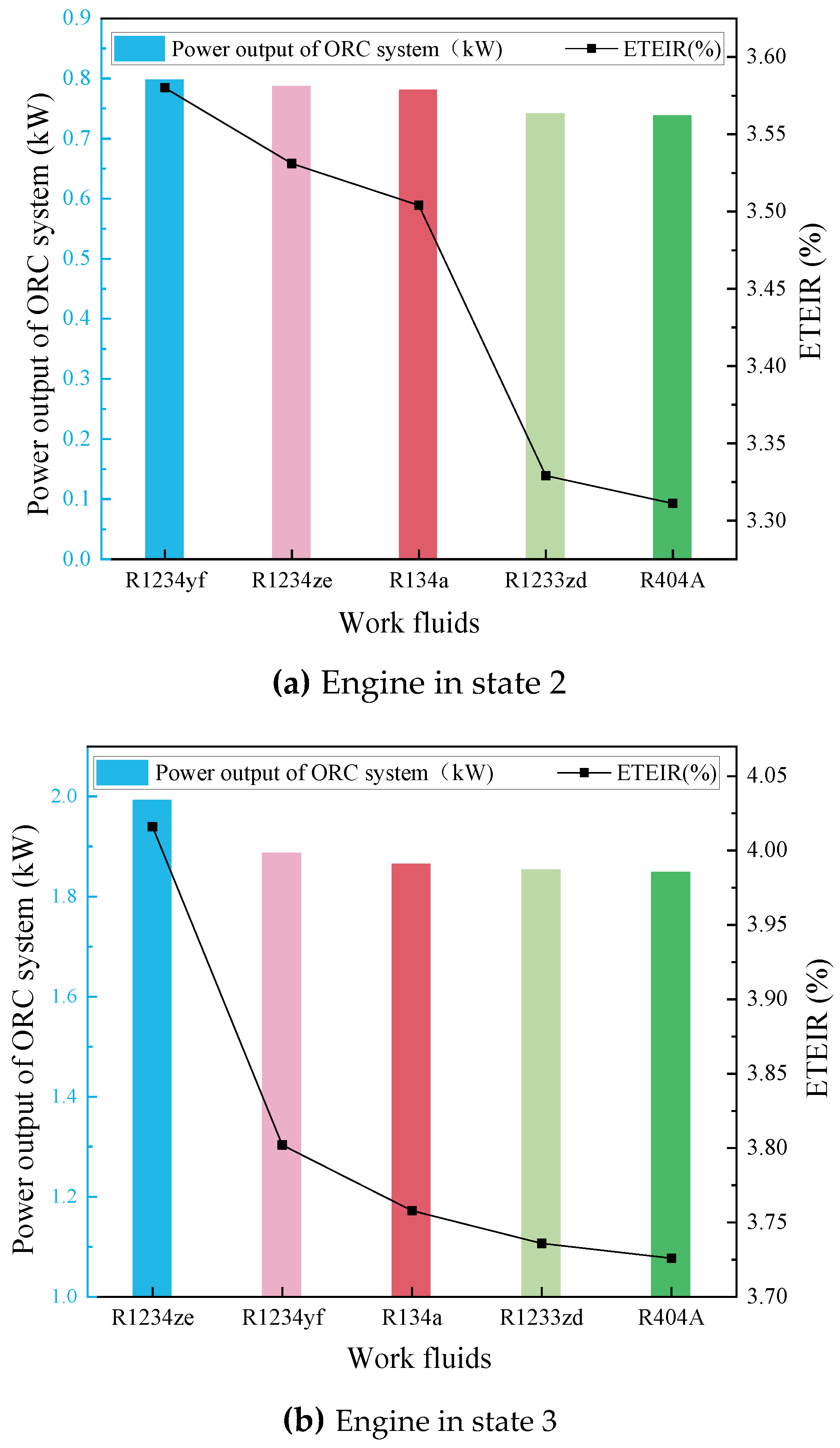
The previous Section 3.1 and Section 3.2 used R134a in the ORC and compound cycle systems, which are common WFs. R134a has been widely used in AC cycle systems since it has no ODP value [29], but the GWP value of R134a is high. In this section, five WFs (R134a, R1234yf, R404A, R1233zd, and R1234ze) are chosen to perform this selection. The properties of the five WFs are shown in Appendix A Table A1. The previous sections demonstrate an optimal supply strategy for WF mass flow rates. Hence, the ten WFs adopt this supply strategy as well. The WHRCS not only concentrates on the system’s power output and ETEIR but also considers an environmentally friendly process. A comparison of the five WFs are shown in Figure 11 and Figure 12. For the ORC system, using R1234yf has a higher power output and ETEIR at low and medium engine speeds, but at medium and high engine speeds, R1234ze performs best. For the compound cycle system, R134a performs best in all three engine states, and R1234yf and R1234ze also performed strongly. However, in contrast with the ORC system, R1234ze has a higher power output and ETEIR at a low engine speed, and R1234yf performs better at medium and high engine speeds. Overall, R1234yf and R1234ze are the preferred choices for an WHRCS with a high system power output and ETEIR, for fewer risks, and for an environmentally friendly process. The maximum recovery power and ETEIR of the compound cycle system using R1234yf reached 3.853 kW and 5.05%, respectively.
4. Discussion
Future research will explore the combination of a WHR system and an HEV to conduct actual road condition tests to evaluate the impact of WHR systems on the fuel consumption and pollutant emissions in real driving cycles in depth. At the same time, the potential negative impact of the WHR system on the vehicle performance will also be considered to provide better technical support for future vehicle design and manufacturing.
5. Conclusions
- The pump speed of an ORC system or compound cycle system has a great influence on the output power of the system. The pump is the key component responsible for transporting the working medium, and its speed directly affects the flow rate of the working fluid and the heat transfer efficiency of the system. In addition, the working state of the engine has a more direct impact on the output power of the system. The increase in the engine speed will lead to an increase in the exhaust gas flow, thus improving the system power output. The composite system achieves an improvement in the maximum power output under different engine conditions, and the power output and engine thermal efficiency ratio are better than the independent system, showing the advantages of the composite system in energy recovery.
- At a low engine speed, the influence of the working medium’s mass flow rate is limited. With a high-speed engine, the sensitivity of the working medium’s mass flow rate is enhanced. Under high-load conditions, increasing the working medium’s mass flow rate appropriately can improve the system performance. Under different engine conditions, selecting the appropriate working medium mass flow rate can maximize the system’s output power and efficiency.
- Comparing the five working mediums, R1234yf and R1234ze are the preferred candidates for the working medium of a waste heat recovery compound system in terms of the system’s output power, ETEIR, and environmental impact.
Future research will explore the combination of a WHR system and am HEV to conduct actual road condition tests to evaluate the impact of WHR systems on the fuel consumption and pollutant emissions in real driving cycles in depth. At the same time, the potential negative impact of the WHR system on the vehicle performance will also be considered to provide better technical support for future vehicle design and manufacturing.
Author Contributions
Conceptualization, Y.H.; Writing—original draft, H.D.; Writing—review & editing, H.D. All authors have read and agreed to the published version of the manuscript.
Funding
This work was supported by the Science Fund of State Key Laboratory of Engine Reliability (skler-201706), and the Technology Development Program of Jilin Province (20180519005JH).
Data Availability Statement
The simulation analyses in this paper are based in part on real operating vehicle data, and for confidentiality reasons, the data in this article will not be disclosed.
Conflicts of Interest
The authors declare no conflicts of interest.
Nomenclatures
| Nomenclature | Acronyms | ||
| P | power (kW) | AC | air conditioning |
| Q | refrigerating capacity (kJ) | ACCM | AC cycle mode |
| W | consumed power (kW) | CCM | compound cycle mode |
| Subscripts | COP | coefficient of performance | |
| EDC | European driving cycle | ||
| EG | exhaust gas | ||
| aux | auxiliary | ETEIR | engine thermal efficiency increase ratio |
| b | battery | GWP | global warming potential |
| com | consumed | HEV | hybrid electric vehicle |
| eng | engine | ICE | internal combustion engine |
| exp | expander | ISG | integrated starter generator |
| exp, compound | expander in compound cycle | ODP | ozone depletion potential |
| exp, ORC | expander in ORC | ORC | organic Rankine cycle |
| gen | generator | ORCM | ORC mode |
| net | net output | OS | oil storage |
| net, compound | net output in compound cycle | SHEV | series hybrid electric vehicle |
| net, ORC | net output in ORC | SI | spark ignition |
| pump, compound | pump in compound cycle | SOC | state of charge |
| pump, ORC | pump in ORC | TEM | thermoelectric module |
| ref | refrigeration | WF | working fluid |
| tm | traction motor | WHR | waste heat recovery |
| WHRCS | waste heat recovery compound system | ||
Appendix A

Table A1.
Thermodynamic/thermophysics and environmental properties of five working fluids.
| Comparative Parameters | R134a | R1234yf | R404A | R1233zd | R1234ze |
|---|---|---|---|---|---|
| Molar Mass (g/mol) | 102.03 | 114.04 | 97.60 | 130.51 | 114.0 |
| Critical Temperature (°C) | 101.1 | 94.7 | 71.97 | 165.6 | 109.4 |
| Critical Pressure (MPa) | 4.07 | 3.38 | 3.72 | 35.7 | 3.636 |
| Critical Density (kg/m3) | 511 | 475 | 484.17 | 478.92 | 1163.0 |
| Normal Boil Point (°C) | −26.2 | −29.5 | −46.8 | 18.32 | −18.95 |
| GWP (100 years) | 1300 | 4 | 0.94 | 1 | <1 |
| ODP | 0 | 0 | 0 | 0 | 0 |
| Safety Group | A1 | A2 | A1 | A1 | A2 |
| Remark | HFC | HFO | HFC | HFO | HFO |
References
- Wang, A.; Xu, J.; Zhang, M.; Zhai, Z.; Song, G.; Hatzopoulou, M. Emissions and fuel consumption of a hybrid electric vehicle in real-world metropolitan traffic conditions. Appl. Energy 2022, 306, 118077. [Google Scholar] [CrossRef]
- Sato, S.; Jiang, Y.J.; Russell, R.L.; Miller, J.W.; Karavalakis, G.; Durbin, T.D.; Johnson, K.C. Experimental driving performance evaluation of battery-powered medium and heavy duty all-electric vehicles. Int. J. Electr. Power 2022, 141, 108100. [Google Scholar] [CrossRef]
- Feng, H.; Ye, J.; Xiong, W.; Gong, Q.; Xu, J. Delay-Dependent MIMO Robust Control for Power Following System of Auxiliary Power Unit in Series Hybrid Electric Vehicles. IEEE Trans. Veh. Technol. 2021, 70, 4353–4365. [Google Scholar] [CrossRef]
- Zhuang, W.C.; Li, S.B.; Zhang, X.W.; Kum, D.; Song, Z.Y.; Yin, G.D.; Ju, F. A survey of powertrain configuration studies on hybrid electric vehicles. Appl. Energy 2020, 262, 114553. [Google Scholar] [CrossRef]
- Domingues, A.; Santos, H.; Costa, M. Analysis of vehicle exhaust waste heat recovery potential using a Rankine cycle. Energy 2013, 49, 71–85. [Google Scholar] [CrossRef]
- Aghaali, H.; Ngstrm, H.E. A review of turbocompounding as a waste heat recovery system for internal combustion engines. Renew. Sust. Energ. Rev. 2015, 49, 813–824. [Google Scholar] [CrossRef]
- Rodriguez, R.; Preindl, M.; Cotton, J.S.; Emadi, A. Review and Trends of Thermoelectric Generator Heat Recovery in Automotive Applications. IEEE Trans. Veh. Technol. 2019, 68, 5366–5378. [Google Scholar] [CrossRef]
- Lin, S.; Zhao, L.; Deng, S.; Ni, J.X.; Zhang, Y.; Ma, M.L. Dynamic performance investigation for two types of ORC system driven by waste heat of automotive internal combustion engine. Energy 2019, 169, 958–971. [Google Scholar] [CrossRef]
- Takahisa, Y.; Tomohiko, F.; Norio, A.; Koichi, M. Design and testing of the Organic Rankine Cycle. Energy 2014, 3, 239–251. [Google Scholar]
- Shafikhani, I.; Aslund, J. Analytical Solution to Equivalent Consumption Minimization Strategy for Series Hybrid Electric Vehicles. IEEE Trans. Veh. Technol. 2021, 70, 2124–2137. [Google Scholar] [CrossRef]
- Anselma, P.G.; Biswas, A.; Belingardi, G.; Emadi, A. Rapid assessment of the fuel economy capability of parallel and series—Parallel hybrid electric vehicles. Appl. Energy 2020, 275, 115319. [Google Scholar] [CrossRef]
- Hsiao, Y.Y.; Chang, W.C.; Chen, S.L. A mathematic model of thermoelectric module with applications on waste heat recovery from automobile engine. Energy 2010, 35, 1447–1454. [Google Scholar] [CrossRef]
- Smith, K.; Thornton, M. Feasibility of Thermoelectric for Waste Heat Recovery in Hybrid Vehicles; National Energy Research Lab. (NREL): Golden, CO, USA, 2007; p. CP-540-42256. [Google Scholar]
- Wang, R.C.; Wei, Y.; Meng, X.P. Performance investigation and energy optimization of a thermoelectric generator for a mild hybrid vehicle. Energy 2018, 162, 1016–1028. [Google Scholar] [CrossRef]
- Vijayagopal, R.; Rousseau, A. Impact of TEGs on the Fuel Economy of Conventional and Hybrid Vehicles; SAE Technical Papers; SAE International: Warrendale, PA, USA, 2015; Volume 28, pp. 2835–2838. [Google Scholar]
- Fang, W.; Quan, S.H.; Xie, C.J.; Tang, X.F.; Ran, B.; Jiao, Y.T. Energy optimization for a weak hybrid power system of an automobile exhaust thermoelectric generator. J. Electron. Mater. 2017, 46, 6617–6627. [Google Scholar] [CrossRef]
- Deng, Y.D.; Fan, W.; Ling, K. A 42–V electrical and hybrid driving system based on a vehicular waste–heat thermoelectric generator. J. Electron. Mater. 2012, 41, 1698–1705. [Google Scholar] [CrossRef]
- Galloni, E.; Fontana, G.; Staccone, S. Design and experimental analysis of a mini ORC (organic Rankine cycle) power plant based on R245fa working fluid. Energy 2015, 90, 768–775. [Google Scholar] [CrossRef]
- Shu, G.Q.; Zhao, M.R.; Tian, H.; Wei, H.Q.; Liang, X.Y.; Huo, Y.Z.; Zhu, W.J. Experimental investigation on thermal OS/ORC (Oil Storage/Organic Rankine Cycle) system for waste heat recovery from diesel engine. Energy 2016, 107, 693–706. [Google Scholar] [CrossRef]
- Zhang, Y.M.; Han, Y.Q.; Yan, J.Y.; Chen, R.L. Thermodynamic analysis of compound cycle system for automotive waste heat recovery and air conditioning refrigeration. Energ. Convers. Manag. 2018, 168, 32–48. [Google Scholar] [CrossRef]
- Braimakis, K.; Karellas, S. Integrated thermoeconomic optimization of standard and regenerative ORC for different heat source types and capacities. Energy 2017, 121, 570–598. [Google Scholar] [CrossRef]
- Trapp, C.; Colonna, P. Efficiency Improvement in Precombustion CO2 Removal Units with a Waste–Heat Recovery ORC Power Plant. J. Eng. Gas. Turb Power 2013, 135, 042311. [Google Scholar] [CrossRef]
- Mastrullo, R.; Mauro, A.W.; Revellin, R.; Viscito, L. Modeling and optimization of a shell and louvered fin mini–tubes heat exchanger in an ORC powered by an internal combustion engine. Energy Convers. Manag. 2015, 101, 697–712. [Google Scholar] [CrossRef]
- Shu, G.Q.; Yu, G.P.; Tian, H.; Wei, H.Q.; Liang, X.Y.; Huang, Z.Y. Multi-approach evaluations of a cascade-Organic Rankine Cycle (C-ORC) system driven by diesel engine waste heat, Part A—Thermodynamic evaluations. Energy Convers. Manag. 2016, 108, 579–595. [Google Scholar] [CrossRef]
- Uusitalo, A.; Honkatukia, J.; Backman, J.; Nyyssönen, S. Experimental study on charge air heat utilization of large–scale reciprocating engines by means of Organic Rankine Cycle. Appl. Therm. Eng. 2015, 89, 209–219. [Google Scholar] [CrossRef]
- Song, J.; Song, Y.; Gu, C.W. Thermodynamic analysis and performance optimization of an Organic Rankine Cycle (ORC) waste heat recovery system for marine diesel engines. Energy 2015, 82, 976–985. [Google Scholar] [CrossRef]
- Zhang, H.G.; Wang, E.H.; Fan, B.Y. A performance analysis of a novel system of a dual loop bottoming organic Rankine cycle (ORC) with a light–duty diesel engine. Appl. Energy 2013, 102, 1504–1513. [Google Scholar] [CrossRef]
- Song, J.; Gu, C.W. Analysis of ORC (Organic Rankine Cycle) systems with pure hydrocarbons and mixtures of hydrocarbon and retardant for engine waste heat recovery. Appl. Therm. Eng. 2015, 89, 693–702. [Google Scholar] [CrossRef]
- Yang, K.; Zhang, H.G.; Song, S.S.; Zhang, J.; Wu, Y.T.; Zhang, Y.Q.; Wang, H.J.; Chang, Y.; Bei, C. Performance analysis of the vehicle diesel engine-ORC combined system based on a screw expander. Energies 2014, 7, 3400–3419. [Google Scholar] [CrossRef]
- Shu, G.Q.; Gao, Y.Y.; Tian, H.; Wei, H.Q.; Liang, X.Y. Study of mixtures based on hydrocarbons used in ORC (Organic Rankine Cycle) for engine waste heat recovery. Energy 2014, 74, 428–438. [Google Scholar] [CrossRef]
- Hogerwaard, J.; Dincer, I.; Zamfirescu, C. Analysis and assessment of a new organic Rankine-based heat engine system with/without cogeneration. Energy 2013, 62, 300–310. [Google Scholar] [CrossRef]
- Di Cairano, L.; Nader, W.B.; Nemer, M. A simulation and experimental study of an innovative MAC/ORC/ERC system, ReverCycle with an ejector for series hybrid vehicles. Energy 2021, 230, 120830. [Google Scholar] [CrossRef]
Figure 1.
WHRCS in (a) ACCM, (b) ORCM, (c) CCM.
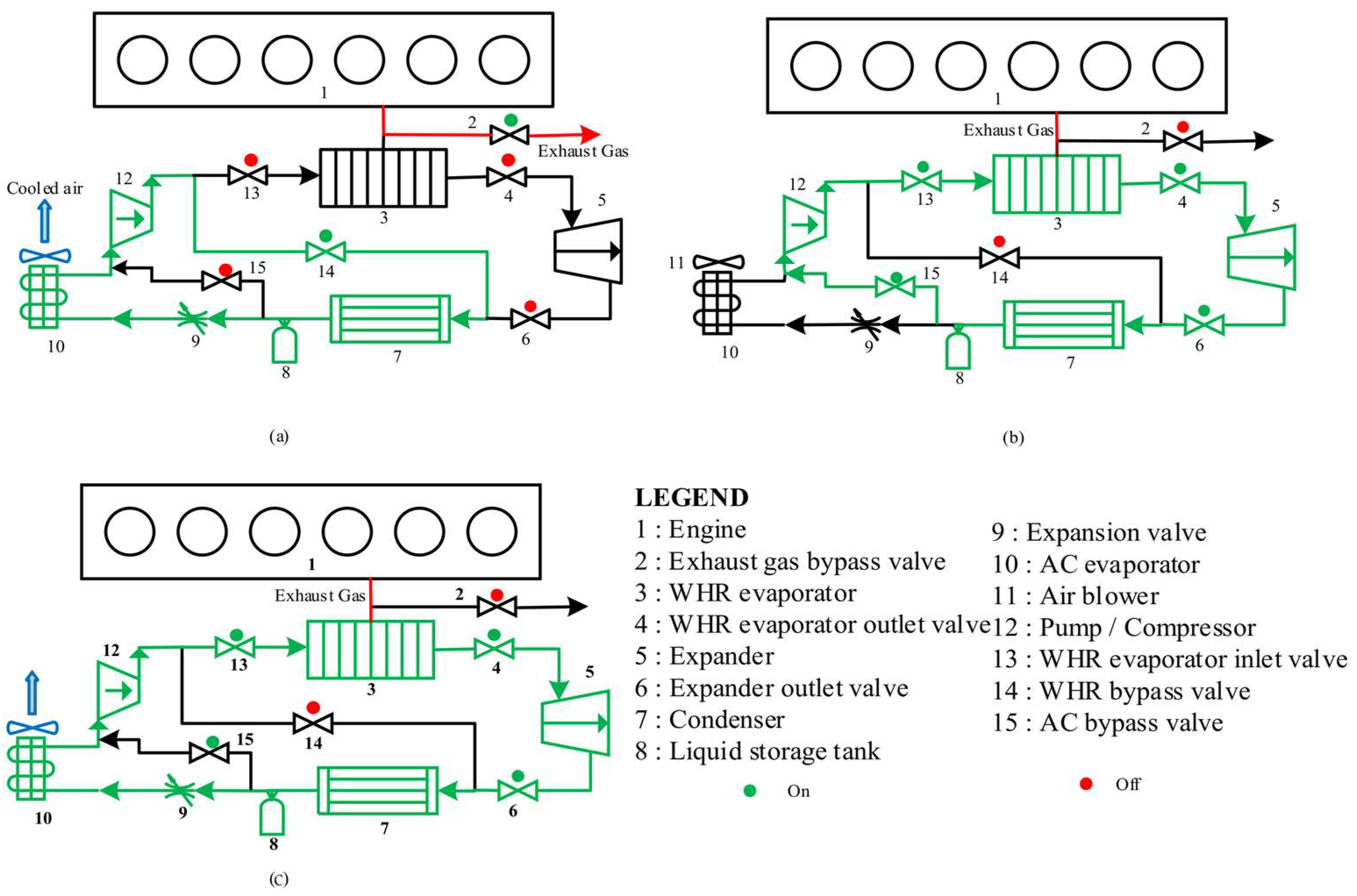
Figure 2.
System control strategy.
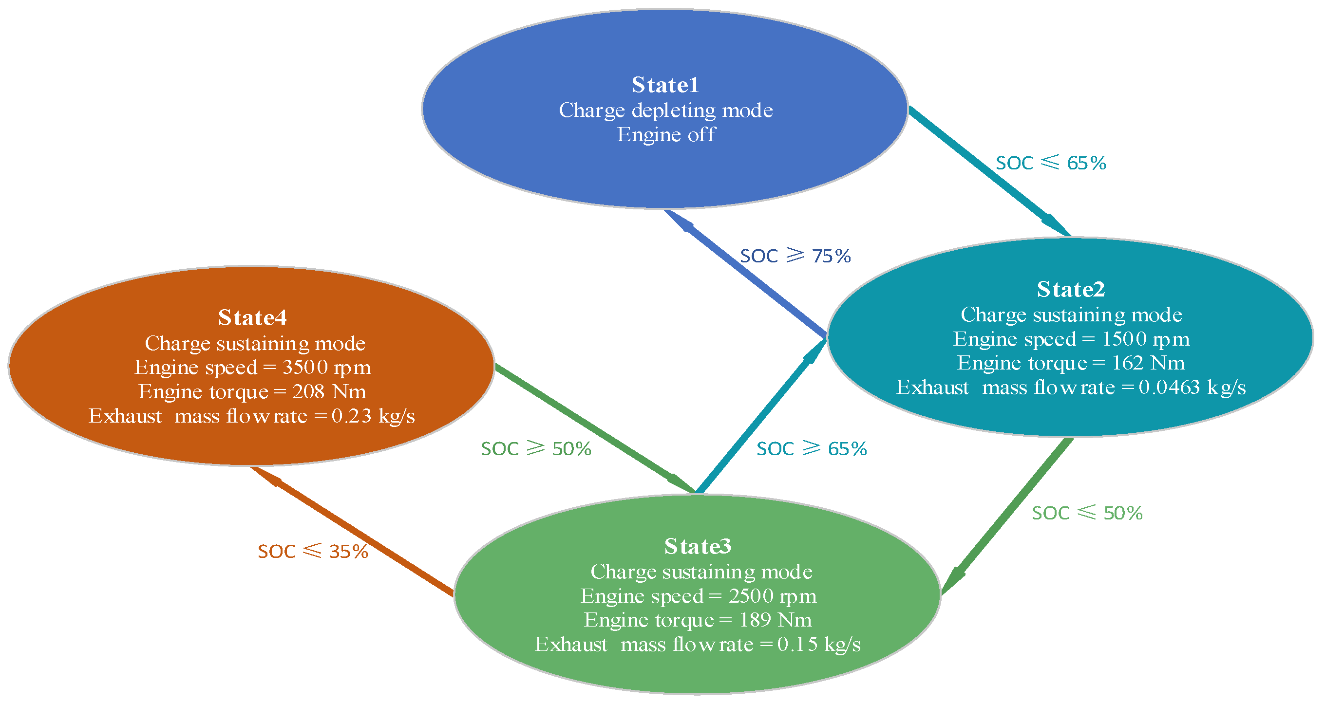
Figure 3.
A physical image of the experimental bench.
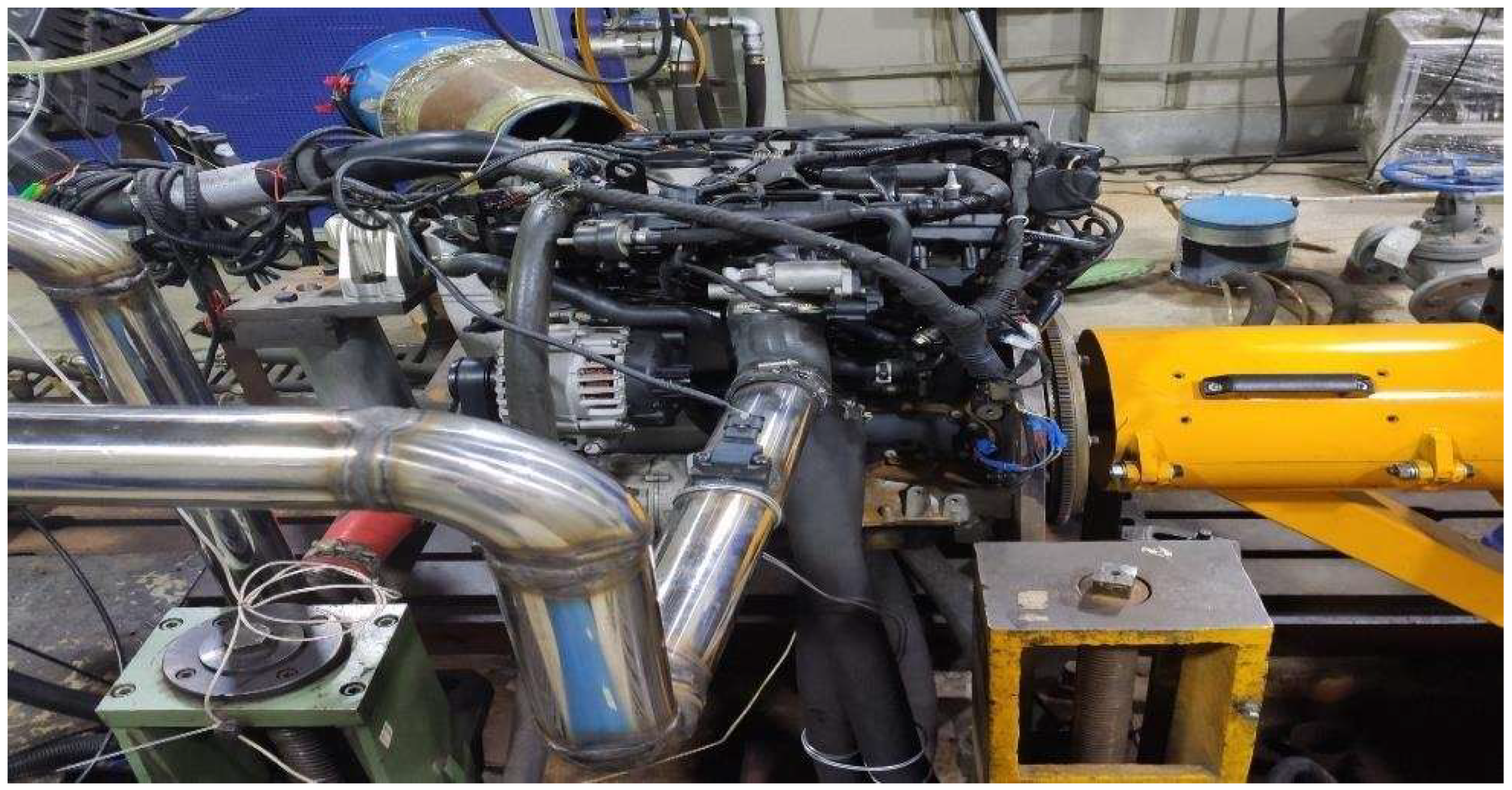
Figure 4.
Comparison of theoretical simulation data and experiments for the gasoline engine.

Figure 5.
Power output of the ORC system at different expander and pump speeds.
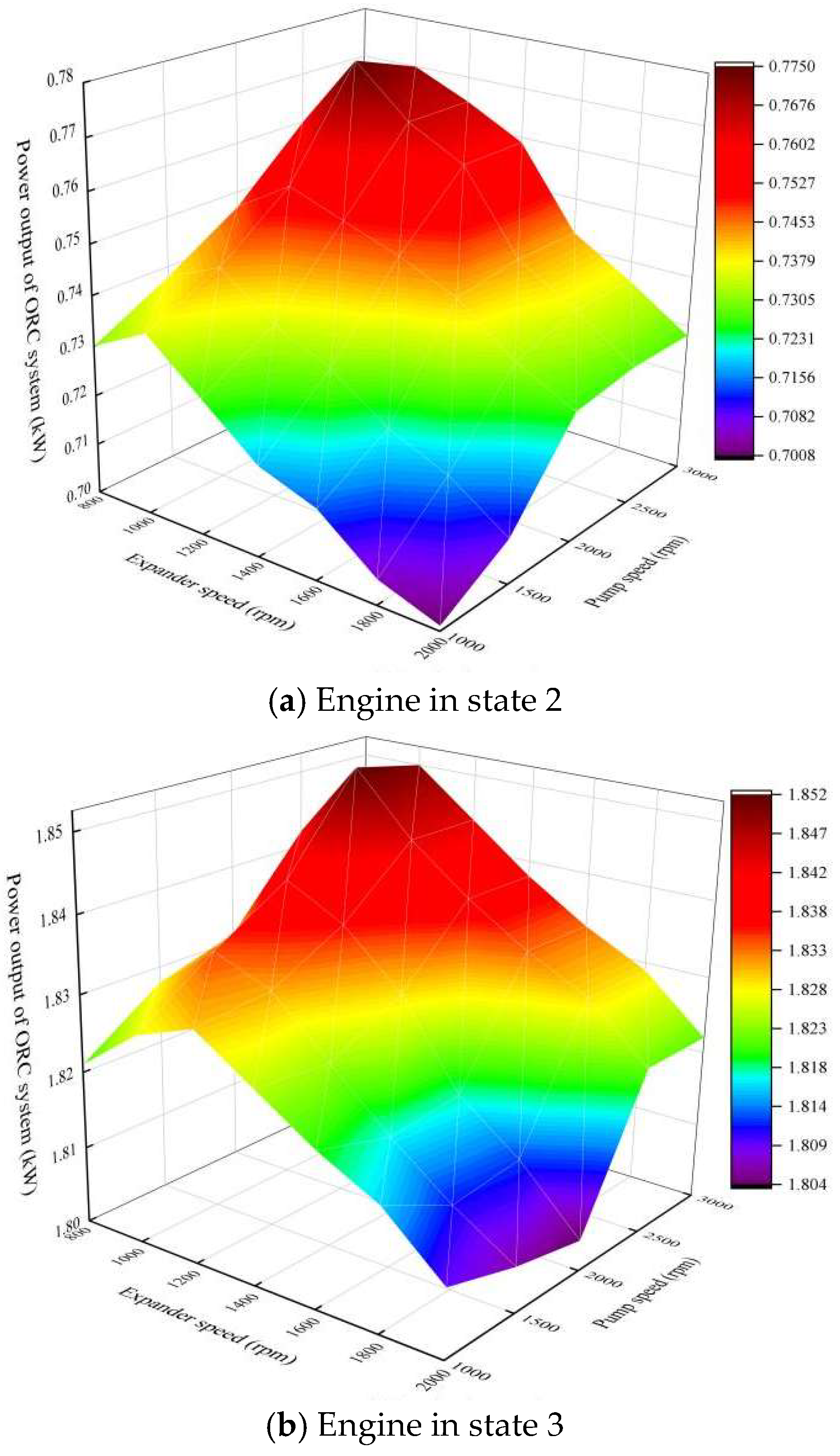
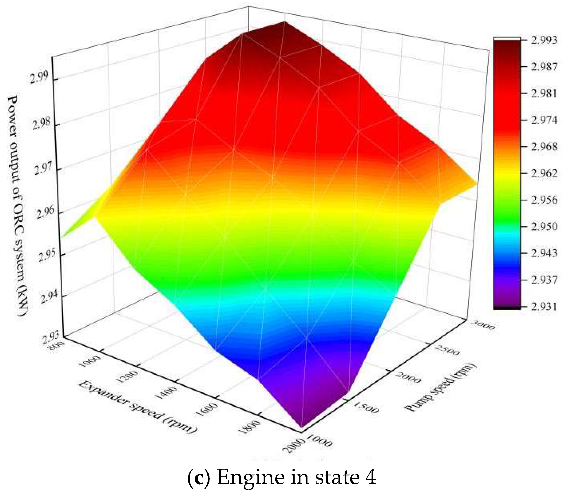
Figure 6.
ETEIR of the ORC system at different expander and pump speeds.

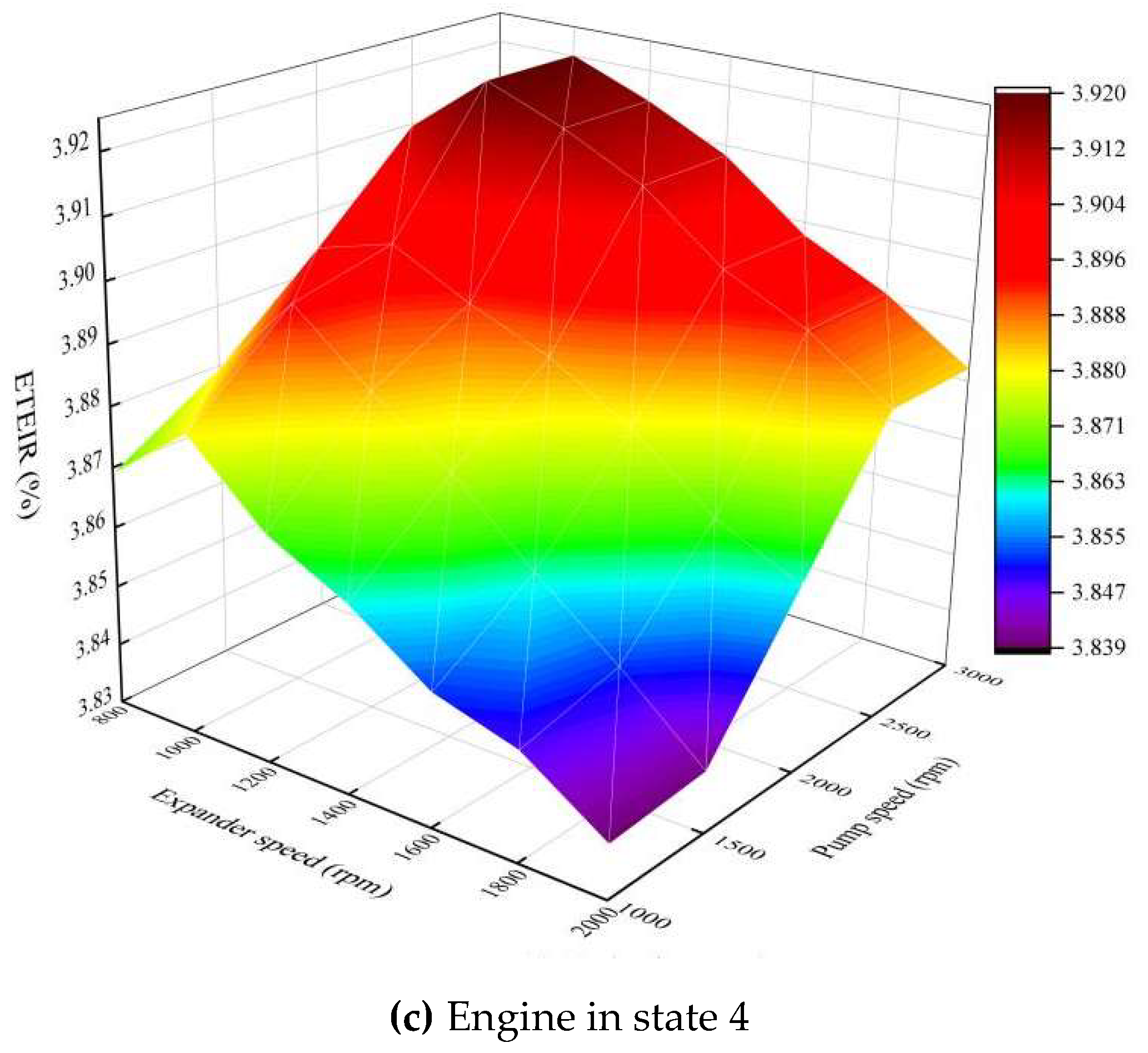
Figure 7.
Power output of the compound cycle system at different expander and pump speeds.

Figure 8.
ETEIR of the compound cycle system at different expander and pump speeds.

Figure 9.
Output power and ETEIR of the ORC system at different R134a mass flow rates.

Figure 10.
Output power and ETEIR of the compound cycle system at different R134a mass flow rates.

Figure 11.
Power output and ETEIR of five different working fluids in ORC system.

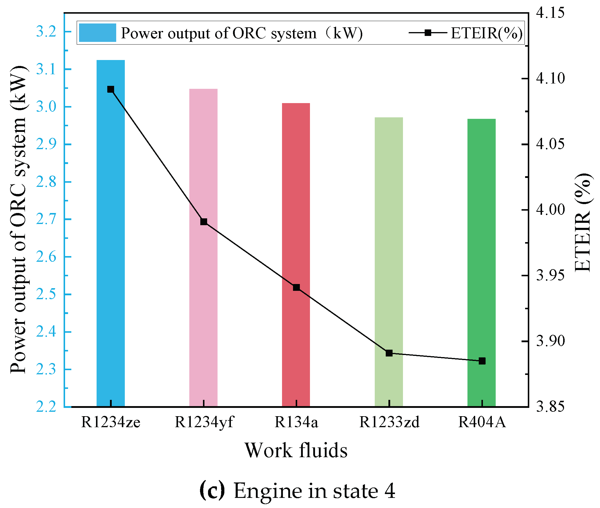
Figure 12.
Power output and ETEIR of five different working fluids in compound cycle system.
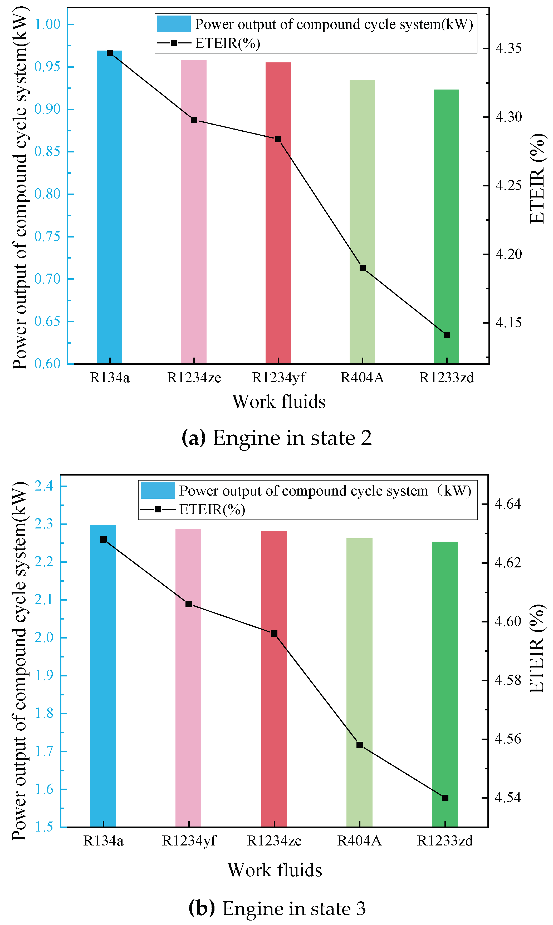

Table 1.
The related parameters of SHEV.
| Project | Parameters | Project | Parameters |
|---|---|---|---|
| Vehicle type | SHEV | Fuel injection method | Direct injection |
| ICE peak power (kW) | 120 | Combustion method | Homogeneous combustion |
| Total engine displacement (L) | 2.0 | Supercharging method | Exhaust turbocharged |
| Number of cylinders | 4 | Fuel system | High-pressure common rail |
| Battery capability (kWh) | 20 | Vehicle weight (kg) | 1600 |
| Compression ratio | 17.0 | Maximum power of generator (kW) | 60 |
| Battery pack voltage (V) | 260 | Maximum generator efficiency | 95% |
Table 2.
Experimental results under full engine load.
| Engine Speed (rpm) | Torque (Nm) | Output Power (kW) | EG Mass Flow Rate (kg/s) | EG Temperature (°C) |
|---|---|---|---|---|
| 1000 | 132.76 | 13.92 | 0.0263 | 621 |
| 1500 | 162.33 | 22.29 | 0.0463 | 627 |
| 2000 | 172.04 | 33.03 | 0.0742 | 629 |
| 2500 | 189.58 | 49.63 | 0.15 | 630 |
| 3000 | 203.58 | 63.95 | 0.16 | 631 |
| 3500 | 208.32 | 76.35 | 0.23 | 634 |
| 4000 | 216.08 | 90.51 | 0.28 | 636 |
| 4500 | 213.07 | 100.40 | 0.42 | 638 |
| 5000 | 209.60 | 109.74 | 0.45 | 642 |
| 5500 | 204.38 | 117.71 | 0.55 | 643 |
Table 3.
Comparison of calculation results with existing research.
| System | WF | Parameters | Results of the Existing Research | Results in This Paper |
|---|---|---|---|---|
| AC system | R134a | COP | 2.07 [26] | 2.24 |
| ORC system | R134a | Output power (kW) | 0.16~0.4 [20] | 0.796~3.009 |
| ETEIR (%) | 2.67~3.9 [20] | 3.57~3.94 | ||
| Compound system | R134a | Output power (kW) | 9.2~9.87 [20] | 0.958~3.856 |
| ETEIR (%) | 5.04~5.37 [20] | 4.29~5.05 |
Disclaimer/Publisher’s Note: The statements, opinions and data contained in all publications are solely those of the individual author(s) and contributor(s) and not of MDPI and/or the editor(s). MDPI and/or the editor(s) disclaim responsibility for any injury to people or property resulting from any ideas, methods, instructions or products referred to in the content. |
© 2024 by the authors. Licensee MDPI, Basel, Switzerland. This article is an open access article distributed under the terms and conditions of the Creative Commons Attribution (CC BY) license (https://creativecommons.org/licenses/by/4.0/).
Share and Cite
MDPI and ACS Style
Dang, H.; Han, Y. Research on the Performance Characteristics of a Waste Heat Recovery Compound System for Series Hybrid Electric Vehicles. Processes 2024, 12, 605. https://doi.org/10.3390/pr12030605
AMA Style
Dang H, Han Y. Research on the Performance Characteristics of a Waste Heat Recovery Compound System for Series Hybrid Electric Vehicles. Processes. 2024; 12(3):605. https://doi.org/10.3390/pr12030605
Chicago/Turabian StyleDang, Huifang, and Yongqiang Han. 2024. "Research on the Performance Characteristics of a Waste Heat Recovery Compound System for Series Hybrid Electric Vehicles" Processes 12, no. 3: 605. https://doi.org/10.3390/pr12030605
Note that from the first issue of 2016, this journal uses article numbers instead of page numbers. See further details here.