
Fluid Dynamics Investigation in a Cold Flow Model of Internal Recycle Quadruple Fluidized Bed Coal Pyrolyzer


Abstract
1. Introduction
2. Experiments
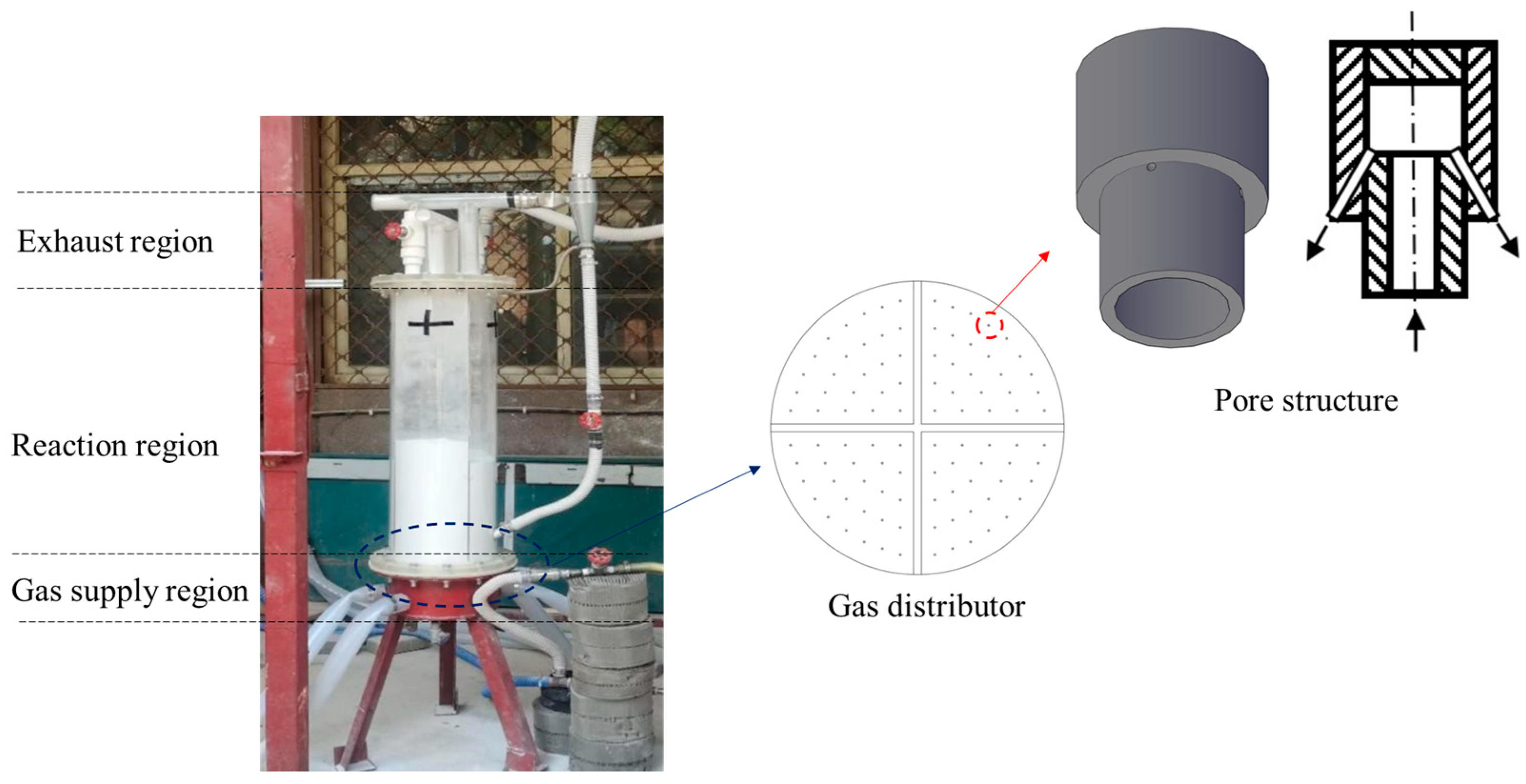
2.1. IR-QFBP Apparatus
2.2. Materials
2.3. Methodology
3. Simulations
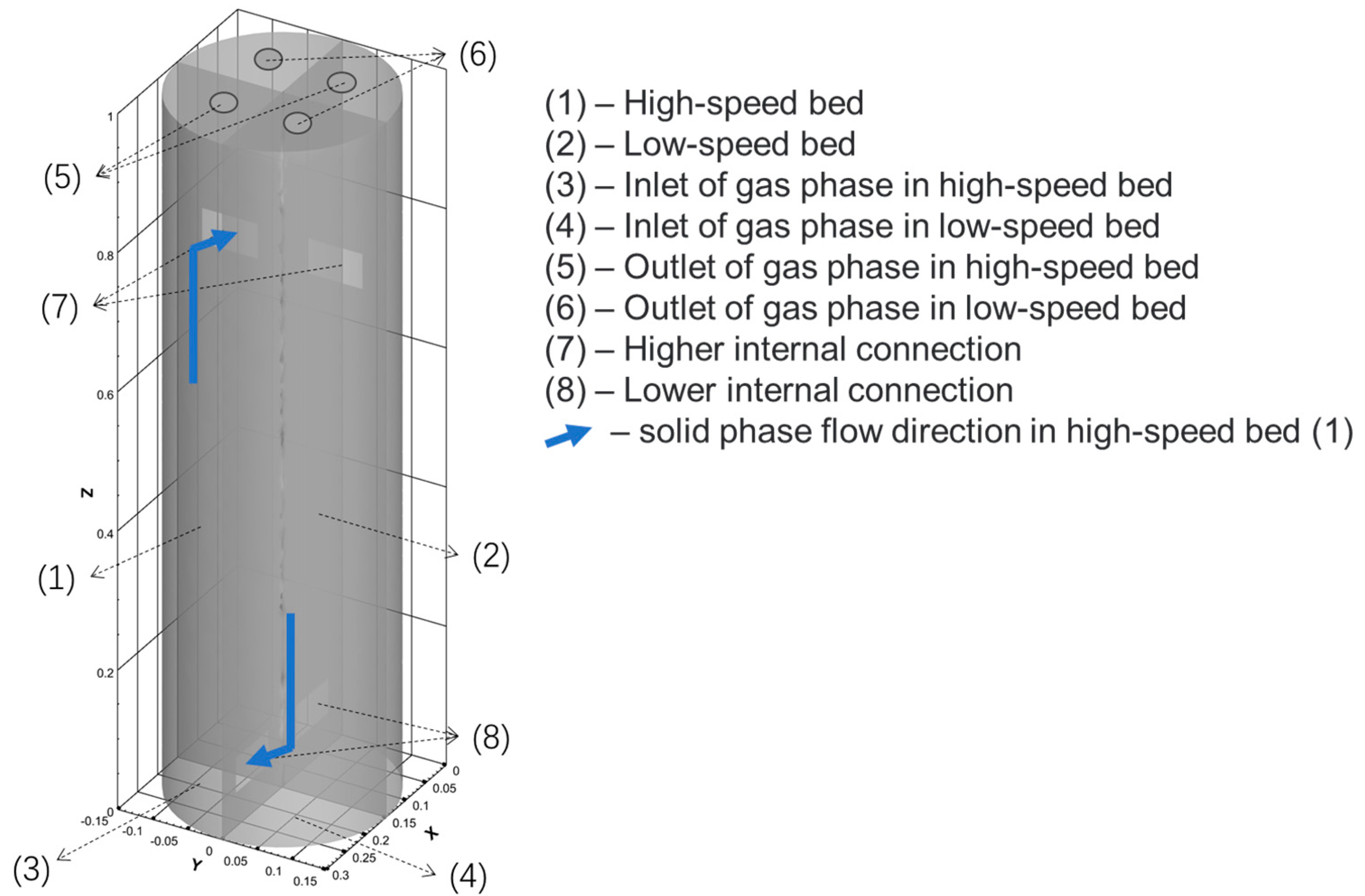
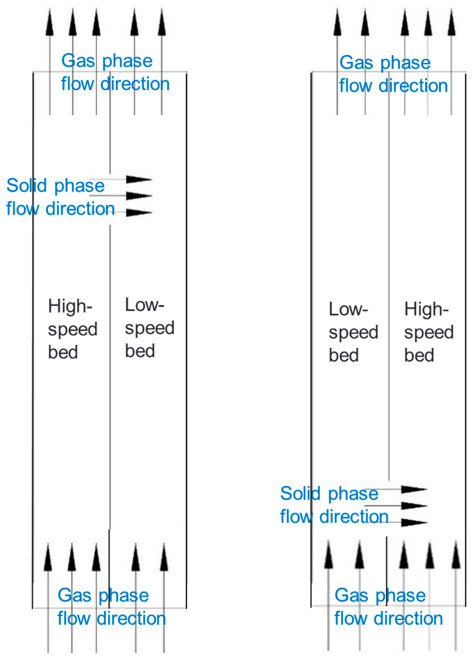
3.1. Physical Model
3.2. Numerical Model
3.3. Simulation Settings
4. Results and Discussion
4.1. Minimum Fluidization Velocity
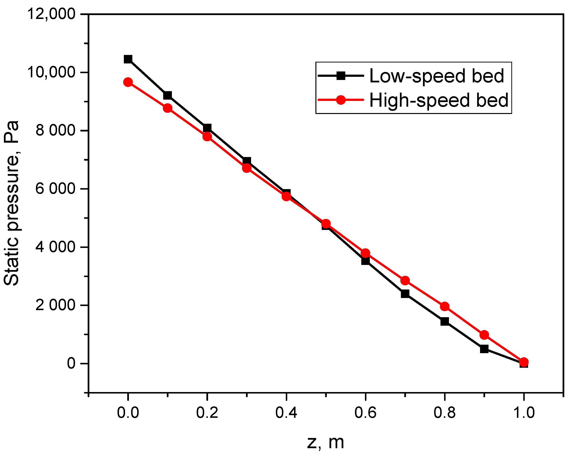
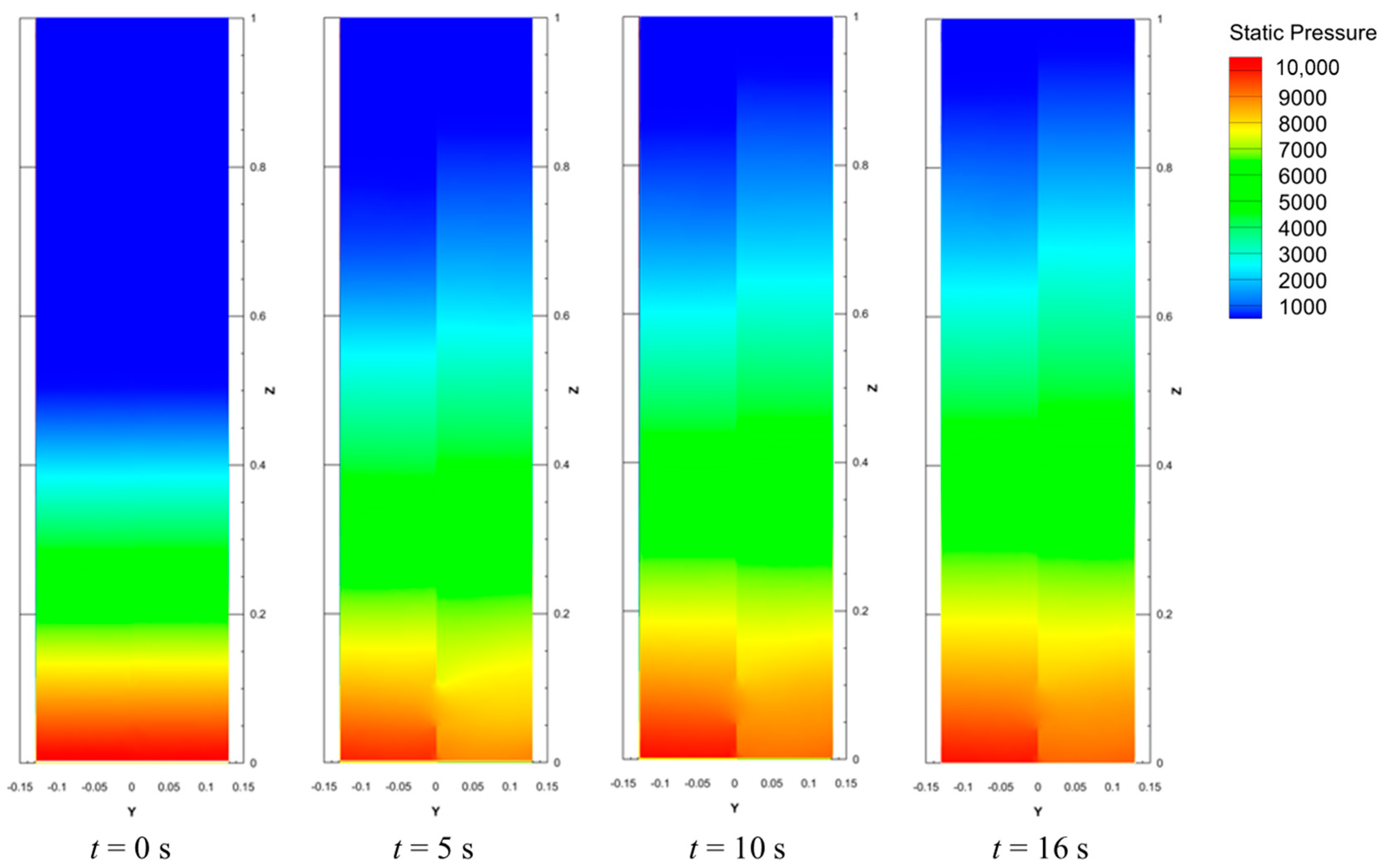
4.2. Pressure Profiles
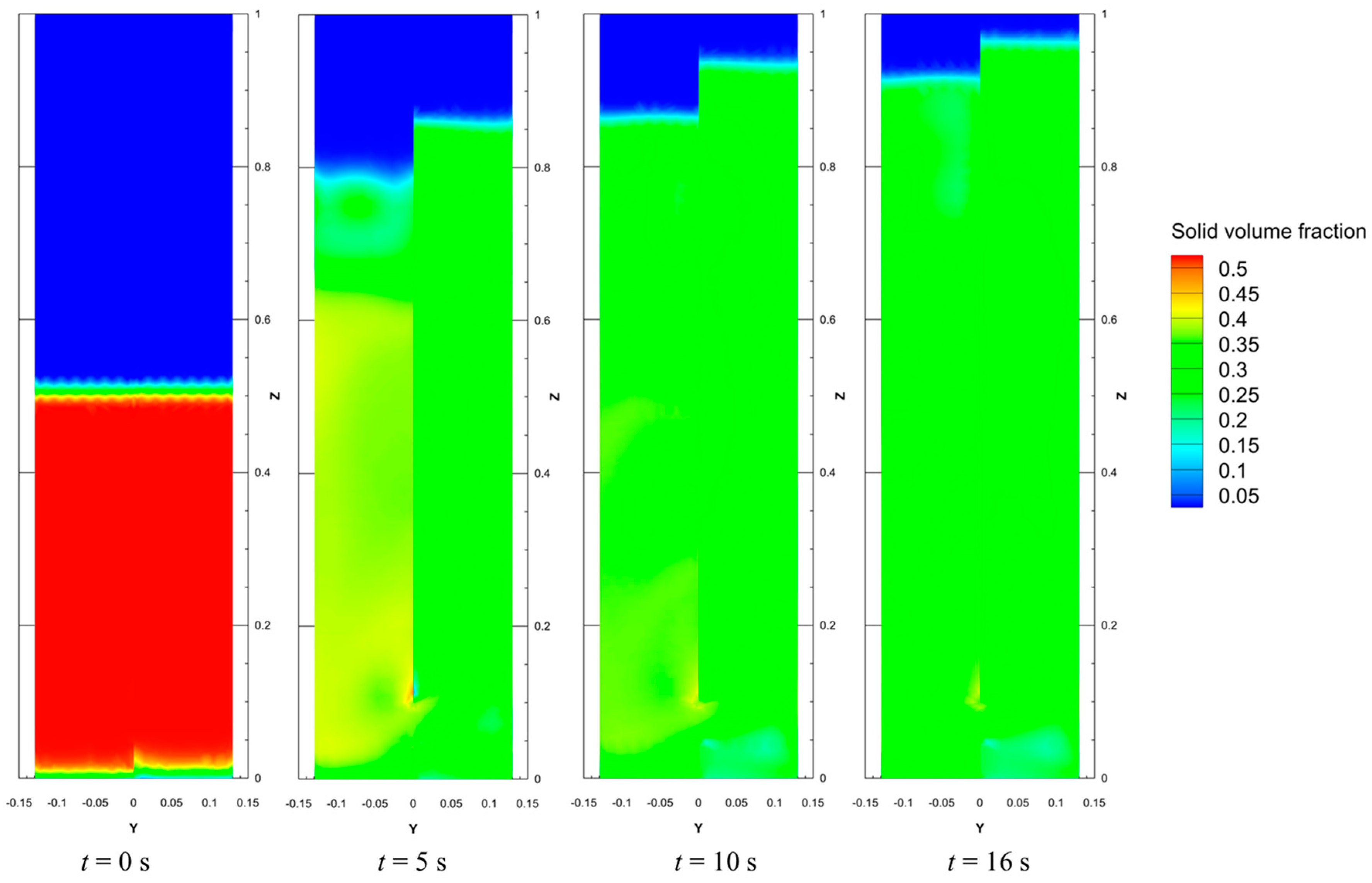
4.3. Fluidization State
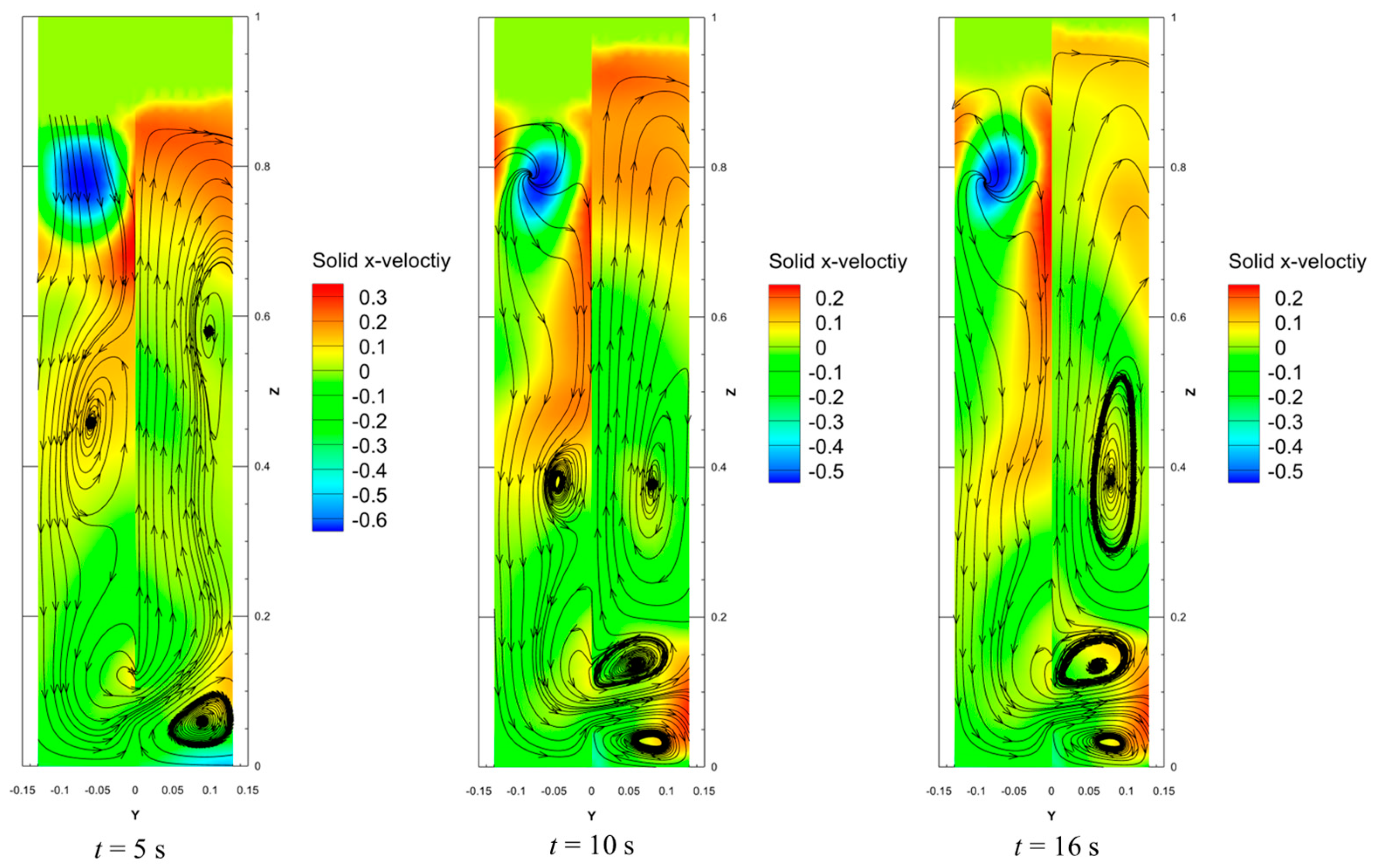
4.4. Velocity Profiles of Solid Phase
4.5. Solid Circulation Rate
5. Conclusions
Author Contributions
Funding
Data Availability Statement
Conflicts of Interest
Nomenclature
| Parameter | |
| ds | Particle diameter, m |
| e | Restitution coefficient |
| g | Gravitational acceleration (m/s2) |
| g0 | Radial distribution function |
| I | Unit tensor |
| ks | Conductivity of fluctuating energy, kg/(m·s) |
| p | Gas pressure, Pa |
| ps | Solid pressure, Pa |
| uf | Gas velocity, m/s |
| us | Solid velocity, m/s |
| Greek letters | |
| αf | Gas volume fraction |
| αs | Solid volume fraction |
| β | Drag coefficient, kg/(m3·s) |
| γ | Collisional dissipation of energy, J/(m3·s) |
| θs | Granular temperature, m2/s2 |
| λs | Solid phase bulk viscosity, Pa·s |
| μf | Gas and solid viscosity, Pa·s |
| μs | Solid viscosity, Pa·s |
| μs,col | Collisional part of solid viscosity, Pa·s |
| μs,kin | Kinetic part of solid viscosity, Pa·s |
| μs,fr | Frictional part of solid viscosity, Pa·s |
| ρf | Gas density, kg/m3 |
| ρs | Solid density, kg/m3 |
| τf | Gas phase stress tensor, Pa |
| τs | Solid phase stress tensor, Pa |
References
- Shi, X.; Wu, Y.; Zhang, J.; Ding, L.; Wang, C.; Lan, X.; Gao, J. Comparison of pyrolysis behavior between pure coal and mixture of coal/CaO. J. Anal. Appl. Pyrolysis 2021, 159, 105311. [Google Scholar] [CrossRef]
- Xue, F.; Li, D.; Guo, Y.; Liu, X.; Zhang, X.; Zhou, Q.; Ma, B. Technical Progress and the Prospect of Low-Rank Coal Pyrolysis in China. Energy Technol. 2017, 5, 1897–1907. [Google Scholar] [CrossRef]
- Wu, Y.; Shi, X.; Wang, C.; Gao, J.; Lan, X. CPFD Simulation of Hydrodynamics, Heat Transfer, and Reactions in a Downer Reactor for Coal Pyrolysis with Binary Particles. Energy Fuels 2019, 33, 12295–12307. [Google Scholar] [CrossRef]
- Shu, Z.; Fan, C.; Li, S.; Wang, J. Multifluid Modeling of Coal Pyrolysis in a Downer Reactor. Ind. Eng. Chem. Res. 2016, 55, 2634–2645. [Google Scholar] [CrossRef]
- Wu, L.; Guan, Y.; Li, C.; Shi, L.; Yang, S.; Reddy, B.R.; Ye, G.; Zhang, Q.; Liew, R.K.; Zhou, J.; et al. Free-radical behaviors of co-pyrolysis of low-rank coal and different solid hydrogen-rich donors: A critical review. Chem. Eng. J. 2023, 474, 145900. [Google Scholar] [CrossRef]
- Zhang, Y.; Zhao, Y.; He, X. Modeling coal pyrolysis in a cocurrent downer reactor. Particuology 2015, 21, 154–159. [Google Scholar] [CrossRef]
- Beis, S.; Onay, Ö.; Koçkar, Ö.M. Fixed-bed pyrolysis of safflower seed: Influence of pyrolysis parameters on product yields and compositions. Renew. Energy 2002, 26, 21–32. [Google Scholar] [CrossRef]
- Pütün, A.E.; Özbay, N.; Önal, E.P.; Pütün, E. Fixed-bed pyrolysis of cotton stalk for liquid and solid products. Fuel Process Technol. 2005, 86, 1207–1219. [Google Scholar] [CrossRef]
- Encinar, J.M.; González, J.F.; González, J. Fixed-bed pyrolysis of Cynara cardunculus L. Product yields and compositions. Fuel Process Technol. 2000, 68, 209–222. [Google Scholar] [CrossRef]
- Ly, H.V.; Kim, S.-S.; Woo, H.C.; Choi, J.H.; Suh, D.J.; Kim, J. Fast pyrolysis of macroalga Saccharina japonica in a bubbling fluidized-bed reactor for bio-oil production. Energy 2015, 93, 1436–1446. [Google Scholar] [CrossRef]
- Xu, R.; Ferrante, L.; Briens, C.; Berruti, F. Flash pyrolysis of grape residues into biofuel in a bubbling fluid bed. J. Anal. Appl. Pyrolysis 2009, 86, 58–65. [Google Scholar] [CrossRef]
- Lee, S.-H.; Eom, M.-S.; Yoo, K.-S.; Kim, N.-C.; Jeon, J.-K.; Park, Y.-K.; Song, B.-H.; Lee, S.-H. The yields and composition of bio-oil produced from Quercus Acutissima in a bubbling fluidized bed pyrolyzer. J. Anal. Appl. Pyrolysis 2008, 83, 110–114. [Google Scholar] [CrossRef]
- Thomsen, T.P.; Sárossy, Z.; Gøbel, B.; Stoholm, P.; Ahrenfeldt, J.; Frandsen, F.J.; Henriksen, U.B. Low temperature circulating fluidized bed gasification and co-gasification of municipal sewage sludge. Part 1: Process performance and gas product characterization. Waste Manag. 2017, 66, 123–133. [Google Scholar] [CrossRef]
- Zuo, W.; Jin, B.; Huang, Y.; Sun, Y.; Li, R.; Jia, J. Pyrolysis of high-ash sewage sludge in a circulating fluidized bed reactor for production of liquids rich in heterocyclic nitrogenated compounds. Bioresour. Technol. 2013, 127, 44–48. [Google Scholar] [CrossRef]
- Lappas, A.A.; Samolada, M.C.; Iatridis, D.K.; Voutetakis, S.S.; Vasalos, I.A. Biomass pyrolysis in a circulating fluid bed reactor for the production of fuels and chemicals. Fuel 2002, 81, 2087–2095. [Google Scholar] [CrossRef]
- Sun, S.; Tian, H.; Zhao, Y.; Sun, R.; Zhou, H. Experimental and numerical study of biomass flash pyrolysis in an entrained flow reactor. Bioresour. Technol. 2010, 101, 3678–3684. [Google Scholar] [CrossRef] [PubMed]
- Dupont, C.; Commandré, J.-M.; Gauthier, P.; Boissonnet, G.; Salvador, S.; Schweich, D. Biomass pyrolysis experiments in an analytical entrained flow reactor between 1073K and 1273K. Fuel 2008, 87, 1155–1164. [Google Scholar] [CrossRef]
- Van de Velden, M.; Baeyens, J.; Brems, A.; Janssens, B.; Dewil, R. Fundamentals, kinetics and endothermicity of the biomass pyrolysis reaction. Renew. Energy 2010, 35, 232–242. [Google Scholar] [CrossRef]
- Ullah, A.; Shabbir, M.B.; Umair, M.; Nadeem, M.; Xin, F. Eulerian CFD analysis of clustering gas-solid flows in fluidized bed pyrolysis reactors. J. Anal. Appl. Pyrolysis 2021, 158, 105261. [Google Scholar] [CrossRef]
- Abaimov, N.; Ryzhkov, A.; Dubinin, A.; Ding, L.; Tuponogov, V.; Alekseenko, S. Investigation into the operation of an auto-thermal two-section subbituminous coal fluidized bed gasifier. Int. J. Coal Sci. Technol. 2023, 10, 37. [Google Scholar] [CrossRef]
- Zhang, J.; Wu, R.; Zhang, G.; Yao, C.; Zhang, Y.; Wang, Y.; Xu, G. Recent Studies on Chemical Engineering Fundamentals for Fuel Pyrolysis and Gasification in Dual Fluidized Bed. Ind. Eng. Chem. Res. 2013, 52, 6283–6302. [Google Scholar] [CrossRef]
- Zhu, Y.; Li, K.; Wang, Q.; Cen, J.; Fang, M.; Luo, Z. Low-rank coal pyrolysis polygeneration technology with semi-coke heat carrier based on the dual-fluidized bed to co-produce electricity, oil and chemical products: Process simulation and techno-economic evaluation. Fuel Process Technol. 2022, 230, 107217. [Google Scholar] [CrossRef]
- Xie, J.; Zhong, W.; Shao, Y.; Zhou, G. Simulation of co-gasification of coal and wood in a dual fluidized bed system. Adv. Powder Technol. 2021, 32, 52–71. [Google Scholar] [CrossRef]
- Yan, L.; Cao, Y.; Li, X.; He, B. Characterization of a dual fluidized bed gasifier with blended biomass/coal as feedstock. Bioresour. Technol. 2018, 254, 97–106. [Google Scholar] [CrossRef]
- Han, Z.; Zeng, X.; Yao, C.; Wang, Y.; Xu, G. Comparison of Direct Combustion in a Circulating Fluidized Bed System and Decoupling Combustion in a Dual Fluidized Bed System for Distilled Spirit Lees. Energy Fuels 2016, 30, 1693–1700. [Google Scholar] [CrossRef]
- Hejazi, B.; Grace, J.R.; Bi, X.; Mahecha-Botero, A. Kinetic Model of Steam Gasification of Biomass in a Dual Fluidized Bed Reactor: Comparison with Pilot-Plant Experimental Results. Energy Fuels 2017, 31, 12141–12155. [Google Scholar] [CrossRef]
- Liu, J.; Zhu, Z.; Jiang, H.; Lu, Q.; Zhang, H. Gasification of Bituminous Coal in a Dual-Bed System at Different Air/Coal Ratios. Energy Fuels 2015, 29, 496–500. [Google Scholar] [CrossRef]
- Zhang, Y.; Wang, Y.; Cai, L.; Yao, C.; Gao, S.; Li, C.-Z.; Xu, G. Dual bed pyrolysis gasification of coal: Process analysis and pilot test. Fuel 2013, 112, 624–634. [Google Scholar] [CrossRef]
- Ren, J.; Wang, Z.; He, B.; Yan, L.; Wang, Z.; Ding, G.; Ying, Z. Hydrodynamic Characteristics in a Cold Flow Model of Quadruple Fluidized Bed Gasifier. Ind. Eng. Chem. Res. 2020, 59, 4775–4784. [Google Scholar] [CrossRef]
- Yan, L.; Cao, Y.; Li, X.; He, B. On a carbon-negative energy production scheme via a quadruple fluidized bed gasifier. Energy Convers. Manag. 2018, 171, 326–338. [Google Scholar] [CrossRef]
- Yan, L.; He, B. On a clean power generation system with the co-gasification of biomass and coal in a quadruple fluidized bed gasifier. Bioresour. Technol. 2017, 235, 113–121. [Google Scholar] [CrossRef]
- Yan, L.; Jia, Z.; Wang, Z.; He, B.; Fang, B. Numerical Research on Biomass Gasification in a Quadruple Fluidized Bed Gasifier. Processes 2022, 10, 2526. [Google Scholar] [CrossRef]
- Abaimov, N.; Ryzhkov, A.; Tuponogov, V.; Simbiriatin, L.; Dubinin, A.; Ding, L.; Alekseenko, S. Steam Gasification in a Fluidized Bed with Various Methods of In-Core Coal Treatment. Axioms 2023, 12, 587. [Google Scholar] [CrossRef]
- Yu, Z.; Chen, Y.; Feng, D.; Qian, Y. Process Development, Simulation, and Industrial Implementation of a New Coal-Gasification Wastewater Treatment Installation for Phenol and Ammonia Removal. Ind. Eng. Chem. Res. 2010, 49, 2874–2881. [Google Scholar] [CrossRef]
- Feng, D.; Yu, Z.; Chen, Y.; Qian, Y. Novel Single Stripper with Side-Draw to Remove Ammonia and Sour Gas Simultaneously for Coal-Gasification Wastewater Treatment and the Industrial Implementation. Ind. Eng. Chem. Res. 2009, 48, 5816–5823. [Google Scholar] [CrossRef]
- Shi, J.; Wang, N.; Li, L.; Li, Z.; Han, H. Review on treatment technologies of coal gasification wastewater in China. J. Clean. Prod. 2022, 333, 130166. [Google Scholar] [CrossRef]
- Yuan, Y.; Li, D.; Zhang, L.; Zhu, Y.; Wang, L.; Li, W. Development, Status, and Prospects of Coal Tar Hydrogenation Technology. Energy Technol. 2016, 4, 1338–1348. [Google Scholar] [CrossRef]
- LaMarche, C.Q.; Freireich, B.; Cocco, R.; Chew, J.W. Understanding drag part 1: Well-established drag limits and homogeneous drag laws. Chem. Eng. J. 2023, 471, 144541. [Google Scholar] [CrossRef]
- Nijssen, T.M.J.; Padding, J.T.; Ottens, M. Hydrodynamics of expanded bed adsorption studied through CFD-DEM. Chem. Eng. Sci. 2023, 280, 119027. [Google Scholar] [CrossRef]
- Wu, W.; Leckner, B.; Pallarès, D.; Duan, L. Solids separation efficiency at the outlet of a circulating fluidized bed riser. Powder Technol. 2023, 428, 118748. [Google Scholar] [CrossRef]
- Kunii, D.; Levenspiel, O. Fluidization Engineering; Butterworth-Heinemann: Oxford, UK, 1991. [Google Scholar]
- Gidaspow, D. Multiphase Flow and Fluidization: Continuum and Kinetic Theory Description. J. Non-Newton Fluid. 1994, 55, 207–208. [Google Scholar]
- Liu, X.; Su, J.; Qian, Y.; Cui, L.; Liu, X. Comparison of two-fluid and discrete particle modeling of gas-particle flows in micro fluidized beds. Powder Technol. 2018, 338, 79–86. [Google Scholar] [CrossRef]
- Dai, F.; Zhang, S.; Luo, Y.; Wang, K.; Liu, Y.; Ji, X. Recent Progress on Hydrogen-Rich Syngas Production from Coal Gasification. Processes 2023, 11, 1765. [Google Scholar] [CrossRef]
- Gai, H.; Yang, P.; Zhang, Q.; Lin, M.; Song, H.; Xiao, M.; Huang, T.; Zhu, Q. Dual-dense gas-solid circulating fluidized bed reactor. Fuel 2023, 337, 126872. [Google Scholar] [CrossRef]


| Parameter | Value |
|---|---|
| Height of the reaction region of IR-QFBP (H, mm) | 1000 |
| Diameter of IR-QFBP (D, mm) | 300 |
| Diameter of the gas outlet (mm) | 45 |
| Number of the gas outlets | 4 |
| Diameter of the hole in the inlet gas distributor (mm) | 2 |
| Number of the holes in the inlet gas distributor | 100 |
| Length of the internal connection (Lc, mm) | 80 |
| Width of the internal connection (Wc, mm) | 50 |
| Number of connections | 4 |
| Parameter | Aluminum Oxide | Low-Grade Pulverized Coal |
|---|---|---|
| Particle size (μm) | 60 (average) | 10~70 |
| Particle density (kg/m3) | 3660 | 1900~2900 |
| Specific surface area (m2/g) | 5000 | 800~19,500 |
| Continuity equations | |
| (1) | |
| (2) | |
| Momentum equations | |
| (3) | |
| (4) | |
| where | |
| (5) | |
| (6) | |
| Solid pressure | |
| (7) | |
| Solid phase bulk viscosity | |
| (8) | |
| Solid phase shear viscosity | |
| (9) | |
| (10) | |
| (11) | |
| (12) | |
| (13) | |
| Radial distribution function | |
| (14) | |
| Granular temperature equations | |
| (15) | |
| Conductivity of fluctuating energy | |
| (16) | |
| Collisional energy dissipation | |
| (17) | |
| Inter-phase drag coefficient Gidaspow drag model | |
| (18) | |
| (19) |
| Inlet Velocity of High-Speed Bed (m/s) | Inlet Velocity of Low-Speed Bed (m/s) | Simulated Pressure Differences (Pa) | Experimental Pressure Differences (Pa) | |
|---|---|---|---|---|
| Case 1 | 0.1 | 0.04 | 467.5 | 460 |
| Case 2 | 0.1 | 0.06 | 662.2 | 660 |
| Case 3 | 0.1 | 0.08 | 518.3 | 520 |
| Inlet Velocity of High-Speed Bed (m/s) | Inlet Velocity of Low-Speed Bed (m/s) | Solid Circulation Rate through Lower Connection (kg/s) | Solid Circulation Rate through Higher Connection (kg/s) | |
|---|---|---|---|---|
| Case 1 | 0.1 | 0.04 | 0.46 | 0.46 |
| Case 2 | 0.1 | 0.06 | 0.62 | 0.62 |
| Case 3 | 0.1 | 0.08 | 0.69 | 0.69 |
Disclaimer/Publisher’s Note: The statements, opinions and data contained in all publications are solely those of the individual author(s) and contributor(s) and not of MDPI and/or the editor(s). MDPI and/or the editor(s) disclaim responsibility for any injury to people or property resulting from any ideas, methods, instructions or products referred to in the content. |
© 2024 by the authors. Licensee MDPI, Basel, Switzerland. This article is an open access article distributed under the terms and conditions of the Creative Commons Attribution (CC BY) license (https://creativecommons.org/licenses/by/4.0/).
Share and Cite
Cao, X.; Yu, H.; Wang, J.; Zhou, L.; Hu, Y. Fluid Dynamics Investigation in a Cold Flow Model of Internal Recycle Quadruple Fluidized Bed Coal Pyrolyzer. Processes 2024, 12, 625. https://doi.org/10.3390/pr12030625
Cao X, Yu H, Wang J, Zhou L, Hu Y. Fluid Dynamics Investigation in a Cold Flow Model of Internal Recycle Quadruple Fluidized Bed Coal Pyrolyzer. Processes. 2024; 12(3):625. https://doi.org/10.3390/pr12030625
Chicago/Turabian StyleCao, Xuepu, Haoran Yu, Jianying Wang, Lilong Zhou, and Yongqi Hu. 2024. "Fluid Dynamics Investigation in a Cold Flow Model of Internal Recycle Quadruple Fluidized Bed Coal Pyrolyzer" Processes 12, no. 3: 625. https://doi.org/10.3390/pr12030625
APA StyleCao, X., Yu, H., Wang, J., Zhou, L., & Hu, Y. (2024). Fluid Dynamics Investigation in a Cold Flow Model of Internal Recycle Quadruple Fluidized Bed Coal Pyrolyzer. Processes, 12(3), 625. https://doi.org/10.3390/pr12030625