Article

Research on a Sensorless ADRC Vector Control Method for a Permanent Magnet Synchronous Motor Based on the Luenberger Observer

Beijing Engineering Research Center of Precision Measurement Technology and Instruments, Beijing University of Technology, No. 100, Pingleyuan, Chaoyang District, Beijing 100124, China
*
Author to whom correspondence should be addressed.
Processes 2024, 12(5), 906; https://doi.org/10.3390/pr12050906
Submission received: 23 March 2024 / Revised: 21 April 2024 / Accepted: 24 April 2024 / Published: 29 April 2024
(This article belongs to the Section Process Control and Monitoring)

Abstract

:
A sensorless vector active disturbance rejection control (ADRC) method for permanent magnet synchronous motors (PMSM) utilizing a Luenberger observer is presented. This method aims to address the challenges associated with weak active disturbances, substantial steady-state speed amplitude fluctuations, and difficulty in achieving a balance between overshoot and speed control in the sensorless PMSM control system. Mathematical models of the Luenberger observer and the ADRC were analyzed, leading to the proposal of a second-order ADRC control method based on the Luenberger observer. A mathematical model of the permanent PMSM has been introduced. Additionally, the necessary conditions for the convergence of the Luenberger observer were derived and examined. The allowable range of error feedback gain values was determined, and rotor position data were acquired using a phase-locked loop. The principle of the ADRC was analyzed, and the ADRC simulation results, along with the PI simulation results, were detailed. When the target speed is 1000 r/min, the steady-state error and load disturbance resistance of the ADRC control method outperform those of the PI control method. Finally, the control method was experimentally tested on an STM32F4 chip, demonstrating the advantages of small steady-state error and strong active disturbance ability.

1. Introduction

The permanent magnet synchronous motor (PMSM) offers advantages such as a simple structure, high efficiency, wide speed range, large acceleration and deceleration capabilities, and fast dynamic response [1,2]. With the advancement of power electronics technology, rare earth permanent magnet materials, and advanced control theory, the PMSM has found increasingly widespread applications in fields such as computer numerical control (CNC) machine tools, ships, household appliances, aviation, aerospace, automobiles, and robots [3,4,5]. Mainstream control methods for PMSMs include variable voltage and frequency control, vector control, and direct torque control. Variable voltage and frequency control, essentially an open-loop control method, is susceptible to disturbances. The direct torque control strategy exhibits some torque ripple due to hysteresis comparators [6]. Vector control, also known as field orientation control (FOC), involves multiple coordinate transformations and intricate calculations. Among these control methods, vector control stands out for its superior performance and minimal torque fluctuations.
In FOC control, two methods exist for obtaining rotor position information. One method employs position sensors such as photoelectric encoders, magnetic encoders, and rotary transformers to gather rotor position data. An alternative approach involves estimating the rotor position without the use of a position sensor [7]. Sensorless methods not only reduce cost, size, and weight but also mitigate environmental factors such as drastic temperature and humidity changes, small high-frequency vibrations, and dusty environments. The PMSM’s noninductive control technology can be broadly categorized into two groups: those suitable for medium- and high-speed anti-electromotive force and flux estimation methods and those designed for low- and zero-speed operations with high-frequency injection methods [8,9,10,11]. A key objective of sensorless control is to minimize speed fluctuations.
Position sensors for PMSMs have garnered significant attention from researchers both domestically and internationally. Currently, there is no sensorless control technology that can be universally applied across the entire speed range. Sensorless control methods for medium- and high-speed operations primarily include model reference adaptive control, the sliding mode observer, the extended Kalman filter method, the Luenberger observer method, and advanced artificial intelligence methods. For zero-speed and low-speed operations, sensorless control methods mainly involve the rotating high-frequency injection method and pulse high-frequency injection method [12,13]. In an investigation [14], a PMSM sensorless control based on an extended Kalman filter, which offers strong active disturbance capability, although it involves a substantial number of complex matrix operations, was implemented. Several previous studies have investigated the use of sliding mode observers for sensorless control [15,16], which reduces high-frequency jitter during steady-state operation. Earlier studies [17,18] have introduced the high-frequency injection method to enhance steady-state accuracy by studying the insensitivity strategy of adaptive observers. Finally, some researchers [19,20] have employed a Luenberger observer for noninductive control, expanding the control speed range and enhancing active disturbance resistance.
The most commonly employed control strategy for speed regulation in PMSMs is the use of a PID controller. The fundamental principle of the PID controller is “error-based error elimination,” which offers several advantages, such as a simple structure, fewer adjustment parameters, and ease of implementation. However, the PID controller has limitations, including an inability to address issues of overshoot and speed, tracking lag, susceptibility to external disturbances, and the challenge of adapting a single set of control parameters to different speeds. In cases where the speed range is extensive, multiple sets of coefficients are often required to achieve optimal control outcomes.
The PMSM is a strongly coupled, multivariable, nonlinear control system, with challenges such as load disturbances and parameter perturbations. The ADRC, a novel nonlinear controller introduced by Mr. Han Jingqing of the Chinese Academy of Sciences, is based on a comprehensive analysis of PID control [21,22]. It exhibits excellent dynamic and static characteristics, robust active disturbance handling capabilities, and robustness.
ADRC technology has been widely applied in PMSM speed control systems. Lu W et al. [23] enhanced the tracking accuracy of a PMSM by modeling and simulating an improved ADRC controller. In a study [24], a comparative analysis between first-order ADRC and PID controllers demonstrated that ADRC technology can initiate control without overshoot and offers a faster response speed. A study [25] proposed the linear integration method, which linearizes and parameterizes the extended state observer (ESO) in ADRC for practical implementation. Some studies [26,27,28] have incorporated fuzzy control into ADRC to improve the robustness and dynamic characteristics of PMSM speed control systems. Li J et al. [29] replaced the speed loop with a first-order ADRC controller to investigate changes in controller parameters, yielding favorable control results.
This article establishes a Luenberger observer within a two-phase stationary coordinate system. Furthermore, this article derives the range of error feedback gains K1, K2 required for the convergence of the Luenberger observer. The enhancement of rotor position estimation is achieved by implementing a phase-locked loop. The design principle of the ADRC was analyzed, a simulation model of a noninductive PMSM ADRC FOC control was built based on the Luenberger observer, and the feasibility of a second-order ADRC based on the Luenberger observer was verified. The feasibility of this control strategy was substantiated through experimental validation, including a comparative analysis with traditional PI control. The outcomes of the experiments demonstrated that this control strategy offers several advantages, including a wide speed range, absence of overshoot, rapid response speed, minimal steady-state speed jitter amplitude, and robust active disturbance handling capability.
The second section analyzes the mathematical model of PMSMs, and the third section analyzes the method of estimating the position of PMSMs using the Luenberger observer. The fourth section analyzes the PMSM ADRC control method. The fifth section constructs a sensorless ADRC control model based on the Luenberger observer and conducts simulation and experimental analysis. The sixth section provides an overview of the entire article.

2. Mathematical Model of PMSM

The PMSM represents a nonlinear, strongly coupled multivariable system that experiences interactions between permanent magnets and windings during operation. Additionally, it is affected by nonlinear factors such as magnetic circuit saturation, contributing to a highly intricate electromagnetic relationship. The PMSM mathematical model includes equations for voltage, flux, torque, and mechanical behavior.
For the embedded PMSM, Ld = Lq, and for the surface PMSM, LdLq = Ls Ld and Lq are the stator inductance d-q axis components, and Ls is the stator inductance. For the surface PMSM, the voltage equation in the α-β two-phase stationary coordinate system and the equation in the Park transformation synchronous rotating coordinate system, obtained through Clarke transformation, are denoted as Equations (1) and (2), respectively.
{ u α = R s i α + d ψ α d t u β = R s i β + d ψ β d t
{ u d = R s i d + d ψ d d t ω e L q i q u q = R s i q + d ψ q d t + ω e ( ψ f + L d i d )
Here, uα, uβ, ud, and uq are the stator voltages in the α-β and d-q coordinate systems; iα, iβ, and id, and iq are the stator currents in the α-β and d-q coordinate systems; Rs is the phase resistance; and ψα, ψβ, ψd, and ψq are the excitation winding fluxes of the α-β and d-q axes. The magnetic linkage equations α and α and α and β are
{ ψ α = L s i α + ψ f cos θ e ψ β = L s i β + ψ f sin θ e ω e = p n ω θ e = ω e t = p n ω t
Here, Ls represents the stator inductance, ψf represents the permanent magnet flux, ωe represents the electrical angular velocity, θe represents the electrical angle, θ represents the mechanical angle, ω represents the mechanical angular velocity, and pn represents the polar logarithm.
The torque equation is (4):
T e = 1.5 p n [ ψ f i q + ( L d L q ) i d i q ]
Te represents the electromagnetic torque, and for the surface PMSM, Ld = Lq,
The mechanical torque equation is
J d ω d t = T e T L B ω
J is the moment of inertia, TL is the load torque, and B is the damping coefficient. Combining Equations (1)–(3) yields
{ u α = R s i α + L s d i α d t ψ f p n ω sin ( p n ω t ) u β = R s i β + L s d i β d t + ψ f p n ω cos ( p n ω t )
The back electromotive force of the PMSM is defined as
{ e α = ψ f p n ω sin ( p n ω t ) e β = ψ f p n ω cos ( p n ω t )
The PMSM current state equation obtained by combining (6) and (7) is
{ d i α d t = u α L s R s i α L s e α L s d i β d t = u β L s R s i β L s e β L s

3. Construction of the Luenberger Observer and Estimation of the Rotor Position

3.1. Construction of the Luenberger Observer

A system is deemed observable if it can reconstruct its internal state using detected output values. A state observer is a tool that can estimate the internal state of a system by relying on observed input and output values. In actual operation, the mechanical parameters are much less influential than the electrical parameters are. Equations (7) and (8) can be rewritten as
{ d i α d t = u α L s R s i α L s e α L s d i β d t = u β L s R s i β L s e β L s d e α d t = p n ω e β d e β d t = p n ω e α
Assuming that the input vector is u = [ u α , u β ] T , the intermediate state vector is x = [ i α , i β , e α , e β ] T , and the output vector is y = [ i α , i β ] T , the PMSM state equation can be linearly expressed as
{ x ˙ ( t ) = A x ( t ) + B u ( t ) y ( t ) = C x ( t )
A is the state matrix, B is the input matrix, and C is the output matrix of the Luenberger observer constructed based on the PMSM position sensorless back electromotive force mathematical model. The block diagram of the Luenberger observer model for PMSM is shown in Figure 1.
The PMSM state observation equation can be expressed as
{ x ˙ ^ ( t ) = A x ^ ( t ) + B u ( t ) + K ( y y ^ ) y ^ ( t ) = C x ^ ( t )
K represents the error feedback matrix. The model representation of the PMSM Luenberger observer is
{ d i ^ α d t = u α L s R s i ^ α L s e ^ α L s + K 1 ( i ^ α i α ) d i ^ β d t = u β L s R s i ^ β L s e ^ β L s + K 1 ( i ^ β i β ) d e ^ α d t = p n ω e ^ α + K 2 ( i ^ α i α ) d e ^ β d t = p n ω e ^ β + K 2 ( i ^ β i β )
Discretization processing includes
{ i ^ α ( k + 1 ) = i ^ α ( k ) + T u α ( k ) L s T R s i ^ α ( k ) L s T e ^ α ( k ) L s + T K 1 ( i ^ α ( k ) i α ( k ) ) i ^ β ( k + 1 ) = i ^ β ( k ) + T u β ( k ) L s T R s i ^ β ( k ) L s T e ^ β ( k ) L s + T K 1 ( i ^ β ( k ) i β ( k ) ) e ^ α ( k + 1 ) = e ^ α ( k ) T p n ω e ^ α ( k ) + T K 2 ( i ^ α ( k ) i α ( k ) ) e ^ β ( k + 1 ) = e ^ β ( k ) + T p n ω e ^ β ( k ) + T K 2 ( i ^ β ( k ) i β ( k ) )
According to Equations (12) and (11), the state matrix, input matrix, output matrix, and error feedback matrix can be expressed as follows:
A = [ R s L s 0 1 L s 0 0 R s L s 0 1 L s 0 0 0 p n ω 0 0 p n ω 0 ] K = [ K 1 0 0 K 1 K 2 0 0 K 2 ]   B = [ 1 L s 0 0 1 L s 0 0 0 0 ] C = [ 1 0 0 0 0 1 0 0 ]
To analyze the convergence of the state observer x ˜ , the state error vector is introduced
x ˜ = x x ^
The state error equation is
x ˜ ˙ = x ˙ x ^ ˙ = A x + B u ( ( A K C ) x ^ + K y + B u ) = A x + B u A x ^ + K C x ^ K y B u = A x A x ^ + K C x ^ K y = ( A K C ) ( x x ^ ) = ( A K C ) x ˜
Equation (15) is a homogeneous differential equation, and the solution of Equation (15) is
x ˜ ( t ) = e ( A K C ) t x ˜ ( 0 ) , t > 0
At this stage, it is essential to guarantee that the eigenvalues of the matrix A K C have negative real parts to enable the observed state x ^ to converge toward the actual state x , and the greater the absolute value of the negative real parts of the eigenvalues is, the faster the convergence speed. The characteristic equation of the Luenberger observer is given by:
| λ I ( A K C ) | = [ λ ( λ K 1 + R s L s ) + K 2 L s ] 2 + ( λ K 1 + R s L s ) p n 2 ω 2 = 0
The eigenvalues of this matrix are
λ = 1 2 [ K 1 R s L s ± ( K 1 R s L s ) 2 4 K 2 L s ]
The eigenvalues of a matrix should satisfy
{ K 1 < R s L s K 2 > R s 4 ( K 1 R s L s ) 2
When the error feedback gains K1 and K2 satisfy Equation (18), the state error variable approaches 0 at a certain speed, and the smaller K1 is, the faster the convergence speed is; however, more noise will be generated. By selecting suitable error feedback gains K1 and K2, it is possible to ensure that the estimated back electromotive force closely approximates the actual back electromotive force.

3.2. Estimation of Rotor Position and Speed

Through the observation and calculation of the back electromotive forces e ^ α and e ^ β and the use and utilization of Equations (3) and (7), it becomes possible to determine the position and speed of the rotor as follows:
{ θ e = arctan ( e ^ α e ^ β ) ω = 1 p n d θ e d t
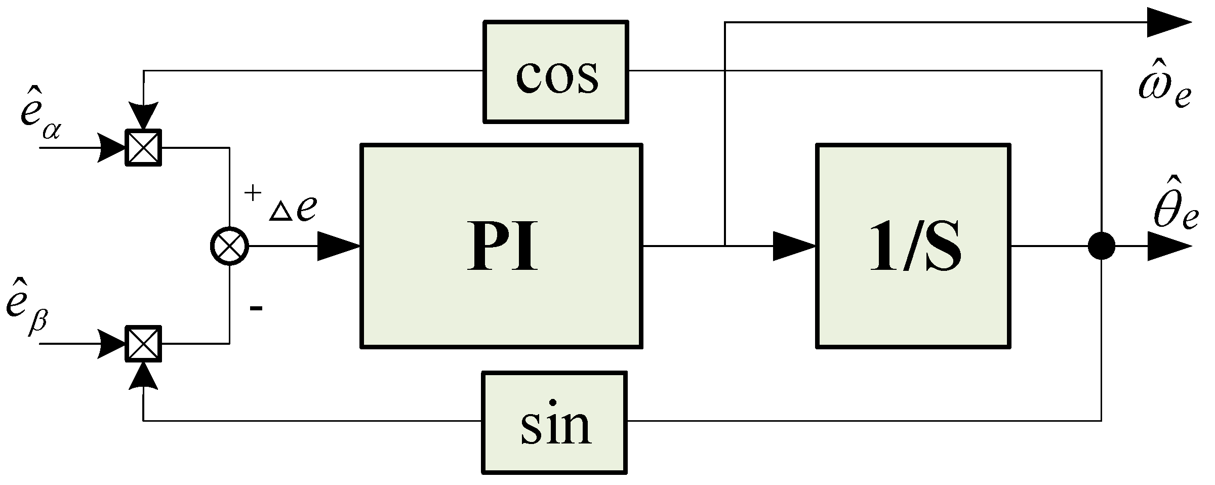
The estimated back electromotive force includes noise signals, particularly at lower speeds. This noise signal becomes more prominent, increasing errors during division and arctangent calculations. A phase-locked loop method is employed to derive the rotor position and speed from the estimated back electromotive force to enhance the estimation accuracy of the rotor position and speed, particularly when the speed is not high and noise signals are prominent. A block diagram illustrating the phase-locked loop for extracting rotor position and speed is depicted in Figure 2.
The angle error signal Δe can be derived from the estimated inverse electromotive force sine–cosine signal. When the estimated angle is very close to the actual angle, sin ( θ e θ ^ e ) ( θ e θ ^ e ) can be considered, and according to the trigonometric function relationship, the following equation can be obtained:
Δ e = e α cos θ ^ e e β sin θ ^ e = ψ f p n ω ( sin θ e cos θ ^ e cos θ e sin θ ^ e ) = n sin ( θ θ ^ ) n ( θ θ ^ )
The mechanism diagram of the phase-locked loop (PLL) according to Formula (21) can be simplified as Figure 3.
According to Figure 3, the transfer function of the PLL is
G ( s ) = θ ^ e θ e = k ( k p + k i s ) 1 s 1 + k ( k p + k i s ) 1 s = k k p s + k k i s 2 + k k p s + k k i
Equation (22) shows that G(s) has a low-pass filtering effect, which can weaken the high-frequency harmonics when estimating the electrical angle. The angle and speed information extracted using a phase-locked loop exhibit superior observation accuracy and increased robustness.

4. Construction of the PMSM Second-Order ADRC

The control of the speed loop and current loop in PMSM control systems mostly relies on the classical PI control strategy, which has low requirements for controller performance and is easy to implement. However, this approach cannot balance system overshoot and speed and has weak resistance to load disturbances. The ADRC builds upon the fundamental concept of error feedback control found in PID controllers, employing errors to rectify errors and resolve the tradeoff between overshoot and fast response. It primarily comprises three components: a tracking differentiator, an extended state observer, and nonlinear error state feedback. This approach does not rely on the mathematical model of the control object, which features a straightforward structure, ease of implementation, and favorable dynamic/static characteristics.
By incorporating PID control as a foundation, this approach introduces methods for “arranging transition processes” and the real-time “extraction of differential signals”. Additionally, an extended state observer is introduced to estimate and counteract the unknown model and external disturbances in real time, thereby enhancing controller performance.
The tracking differentiator (TD) serves as a nonlinear tracking differentiator capable of effectively filtering out higher-order harmonic disturbances in the signal. Properly arranging the transition processes enhances the system response speed, effectively prevents overshoot, and generates the differential signal of the input signal. This results in the swift and accurate tracking of input signals, addressing the tradeoff between response speed and overshoot.
The ADRC treats the unmodeled portion of the system as an internal disturbance, combining it with external disturbances to form the total disturbance of the system. The extended state observer (ESO) not only estimates the system’s state variables but also provides real-time estimates of the “sum disturbance” arising from model uncertainty and external disturbances. This compensates for this in the control law, significantly improving the system’s active disturbance handling capability.
Nonlinear state error feedback (NLSELF) not only compensates for disturbances but also achieves control of the system with the principle of “small errors with large gain and large errors with small gain,” thereby enhancing control accuracy.
The differential equation representation of uncertain objects subject to unknown disturbances is as follows:
{ x n = f ( x , x ˙ , ~ , x ( n 1 ) , t ) + d ( t ) + b u ( t ) y = x ( t )
Here, f ( x , x ˙ , ~ , x ( n 1 ) , t ) represents an unknown function, d(t) represents an unknown disturbance, y represents the system output, and u(t) represents the system control variable. A schematic diagram of the standard ADRC [30] is shown in Figure 4.
If the PMSM corner is known θ and the angle differential signal ω, according to Equations (4) and (5), the second-order state expression of speed ω is
Set   K s = 1.5 p n ψ f ,   T d = T L + B ω
J d ω d t = K s i q T d
J d 2 ω d t 2 = K s d i q d t T ˙ d = K s L q u ^ q K s L q ( u ^ q u q + R s i q + ω ψ f ) T ˙ d = b u ^ q + a ( t )
where a(t) is the disturbance term, b = u d c K s 3 J L q ,
a ( t ) = 1 J [ K s L q ( u ^ q u q + R s i q + ω ψ f ) T ˙ d ] .
Let ω be the state variable x1 and the angular acceleration be the differential x2 of the tracking signal. We expand the disturbance term a(t) to the state variable x3.
The discrete expression of the second-order ADRC for the PMSM speed is as follows:
Tracking differentiator:
{ x 1 ( k + 1 ) = x 1 ( k ) + T x 2 ( k ) x 2 ( k + 1 ) = x 2 ( k ) + T f h a n ( x ( k ) ω ( k ) , x 2 ( k ) , r , h 1 )
T represents the integration step size, while r determines the tracking speed parameter, often referred to as the speed factor. h1 is the filtering factor responsible for determining the filtering effect. In this context, x1(k) represents the tracking signal of the input signal and x2(k) is the differential signal of the input signal. The function fhan(·) denotes the fastest synthesis function of the discrete system.
{ d = r h 1 ; d 0 = h 1 d y = x 1 + h 1 x 2 v ( k ) ; a 0 = d 2 + 8 r | y | a = { x 2 + ( a 0 d ) 2 , | y | > d 0 x 2 + y h 1 , | y | d 0 f s t = { r a d , | a | d r s i g n ( a ) , | a | > d
Extended state observer
{ e = z 1 ( k ) y ( k ) z 1 ( k + 1 ) = z 1 ( k ) + T ( z 2 ( k ) β 01 e ) z 2 ( k + 1 ) = z 2 ( k ) + T ( z 3 ( k ) β 02 f a l ( e ( k ) , α 01 , δ ) + b 0 u ( k ) ) z 3 ( k + 1 ) = z 3 ( k ) T β 03 f a l ( e ( k ) , α 02 , δ )
Among these variables, z1(k) and z2(k) correspond to the differentials of the actual speed output y(k) and the tracked speed output y(k) of the controlled object, respectively. z3(k) represents the summation of disturbances in the controlled object, and it is compensated for by providing feedback to the control variable u(k). The compensation factor for this process is denoted as b0.
Nonlinear state error feedback:
{ e 1 = x 1 ( k ) z 1 ( k ) e 2 = x 2 ( k ) z 2 ( k ) u 0 ( k ) = β 1 f a l ( e 1 , α 1 , δ ) + β 2 f a l ( e 2 , α 2 , δ ) u ( k ) = u 0 ( k ) z 3 ( k ) b 0
The nonlinear feedback function fal(·) is
f a l = { | x | e sgn ( e ) , | e | > δ x δ ( 1 e ) , | e | δ
The fal(·) function represents a mathematical fitting that aims to achieve “small error with large gain, large error with small gain”. Various control techniques, including variable gain PID, fuzzy control, and intelligent control, are built upon this control concept.
To attain optimal control outcomes, it is essential to make judicious adjustments to the control parameters of the tracking differentiator, extended state observer, and nonlinear error feedback components within the ADRC framework.

5. Analysis of the Experimental Results

5.1. Model Simulation and Results Analysis

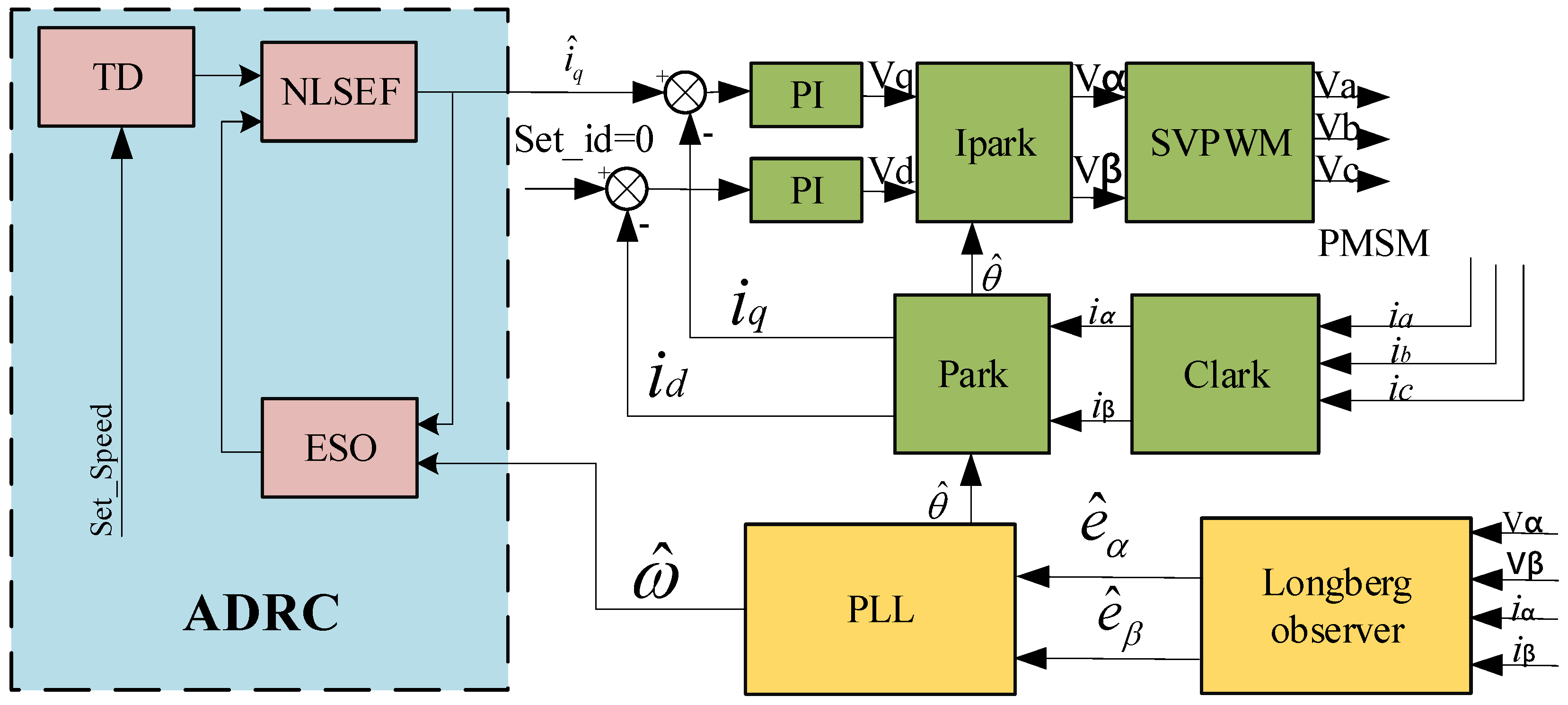
By utilizing a control strategy with id = 0, all stator currents are transformed into torque currents. The structural diagram of the noninductive FOC ADRC for the PMSM, which relies on the Luenberger observer, is depicted in Figure 5. Following the sampling of the three-phase current with a resistor, it is converted into iα and iβ through a Clarke transformation, with one input directed to the Luenberger observer and the other subjected to a Park transformation.
The Luenberger observer results in the back electromotive force e ^ α ,   e ^ β , and after passing through a phase-locked loop, e ^ α ,   e ^ β outputs the estimated angle θ ^ and angular velocity ω ^ . θ ^ participates in the subsequent Park transformation and IPark transformation, where the phase shift of an output from the IPark transformation is 90°. Input A is fed into the space vector modulator (SVPWM), which generates six complementary symmetrical PWM wave control signals to drive the PMSM for rotation. There is still some speed fluctuation in the output speed of the noninductive Luenberger observer. To enhance control quality, an ADRC controller is implemented within the framework of traditional vector control, replacing the PI controller in the speed loop. However, the torque loop and magnetic linkage loop continue to employ PI controllers.
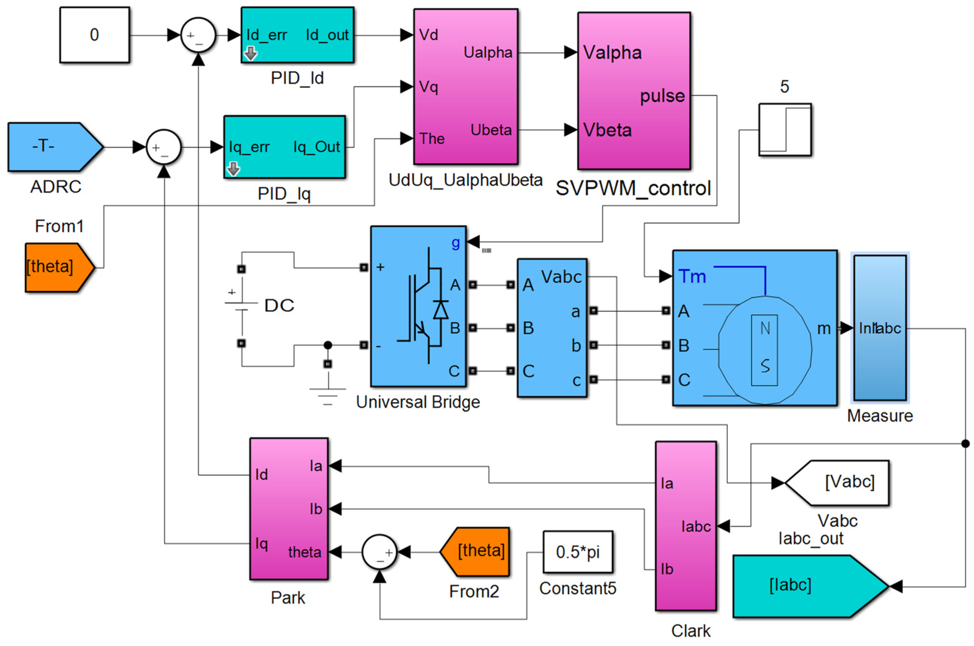
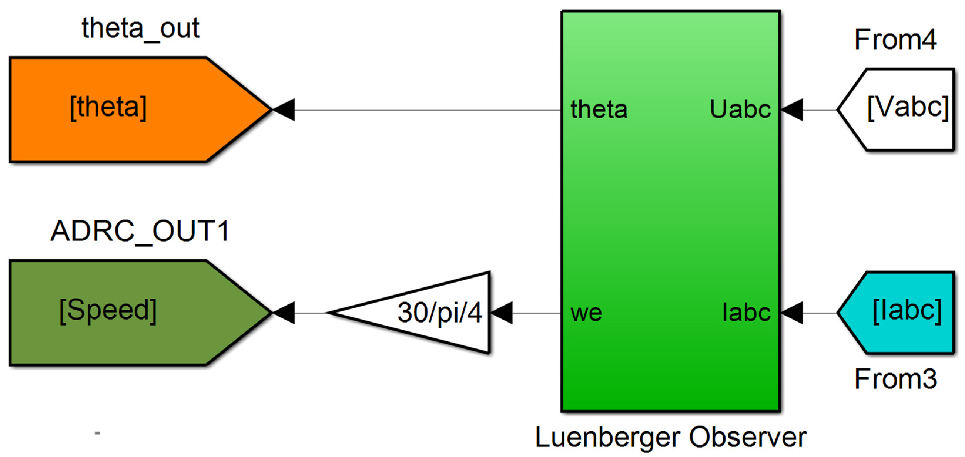
An ADRC simulation model was built based on the Luenberger observer on the Simulink platform, as shown in Figure 6, Figure 7 and Figure 8. During the model building process, modules from the Simulink library were used as much as possible. If it is impractical to measure the Va, Vb, and Vc signals during operation, the outputs Vα and Vβ from the IPark transformation can be directly utilized as inputs for the Luenberger observer.
The control effectiveness of the PI controller and the ADRC controller is verified through the speed step response. The starting speed is set to 1000 r/min, and the control parameters of the PI and ADRC controllers are adjusted to ensure that the time needed for the controller to reach a steady state is basically the same.
The parameters used during the simulation process are shown in Table 1.
The system simulation time was set to 0.5 s, a 4 Nm load was applied to the PMSM at 0.3 s, and the speed, current, and torque simulation test results of the PI and the ADRC were compared.
The results of the speed step response test are shown in Figure 9.
Based on the speed simulation test results, it can be deduced that both the PI control method and the ADRC control method can rapidly reach the desired position. Both achieve the preset target speed in approximately 0.015 s. Following a 0.3 s loading period, both the PI control mode and the ADRC control mode can sustain stable operation.
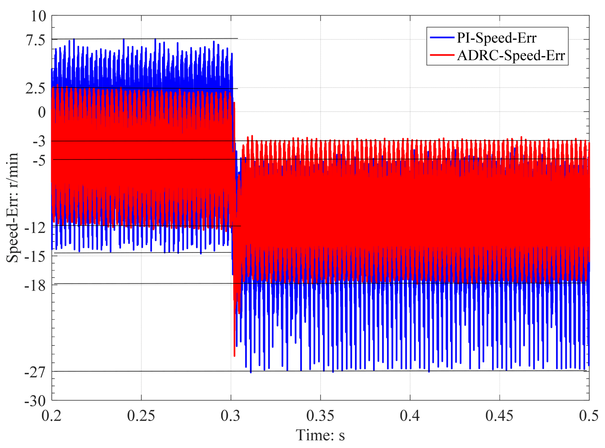
The speed error variation curves of the ADRC and PI control modes during stable operation at speeds ranging from 0.2 s to 0.5 s are shown in Figure 10.
From the speed error variation curve in Figure 10, it can be concluded that both before and after loading, the steady-state speed error of the PI control method is greater than that of the ADRC method.
Before 0.3 s, during steady-state operation without loading, the maximum speed error fluctuation in the PI control mode was 7.5 r/min, with a minimum value of −15 r/min. In contrast, the ADRC control mode exhibited a maximum speed error fluctuation of 2.5 r/min, with a minimum value of −12 r/min. After 0.3 s of loading, during steady-state operation, the maximum speed error fluctuation in the PI control mode was −5 r/min, with a minimum value of −27 r/min. On the other hand, the ADRC control mode had a maximum speed error fluctuation of −3 r/min, with a minimum value of −18 r/min. Overall, the ADRC control method demonstrates superior steady-state error and resistance to load disturbances compared to the PI control method.
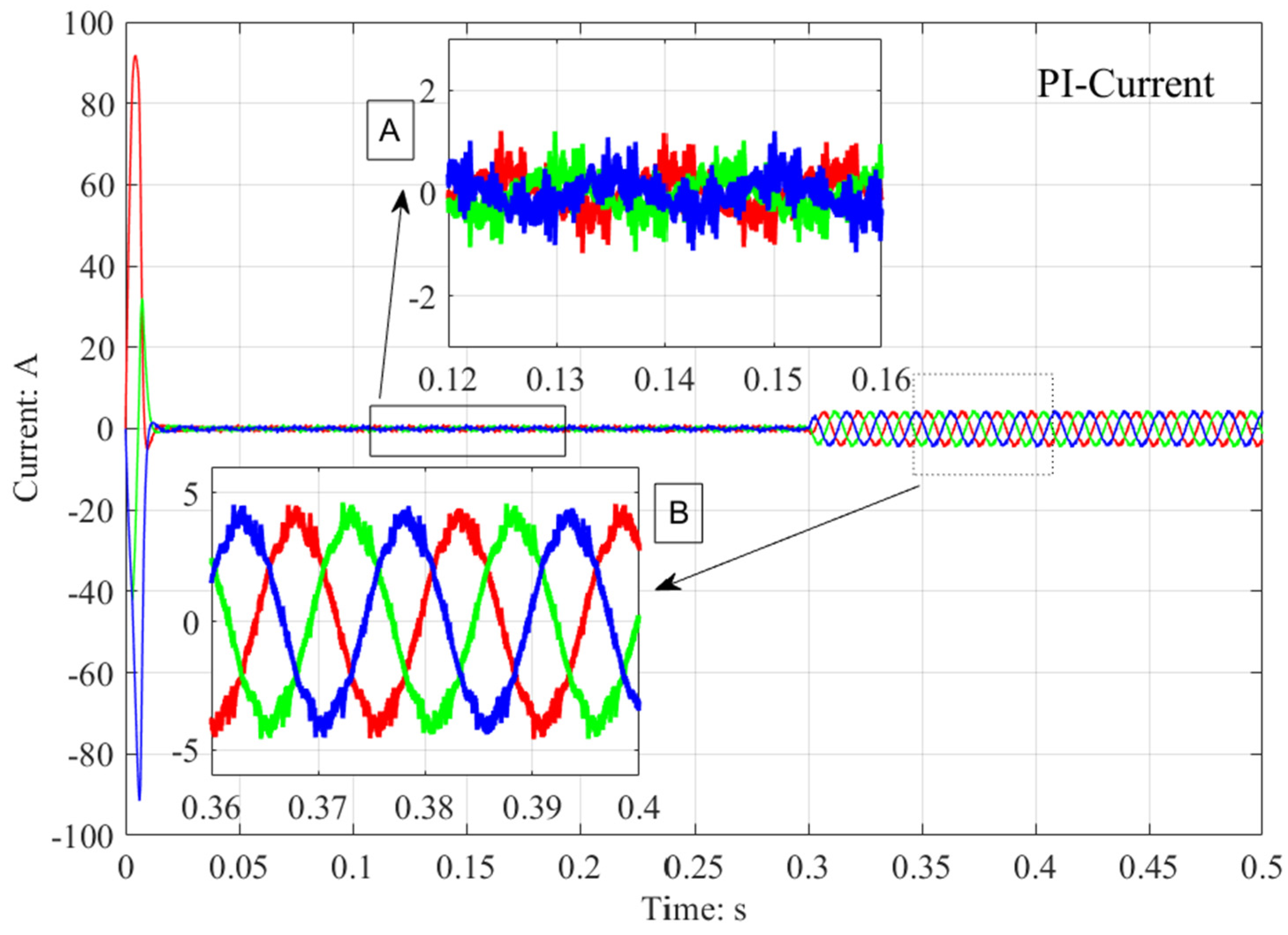
The simulation test results of the three-phase current for the PI control mode and the ADRC control mode during the speed operation are shown in Figure 11 and Figure 12, respectively. The red, green, and blue curves in the figure represent the three-phase current of U, V, W. The locally enlarged figure A in the Figure 11 and Figure 12 represents the current in the no-load state. The locally enlarged figure B in the Figure 11 and Figure 12 represents the current under load condition.
From Figure 11 and Figure 12, it is evident that during the no-load process, when given a target speed, both the three-phase current of the PI control and ADRC control methods increase rapidly. As the speed gradually approaches the specified target speed, the current gradually converges to 0. However, after applying a 4 Nm load for 0.3 s, the three-phase current undergoes an immediate change in a sinusoidal pattern. Figure 11 and the locally enlarged inset A in Figure 12 reveal that during no-load operation, the three-phase current amplitudes in both control methods are small. However, the PI control method exhibits significant sinusoidal current distortion. At this time, the electromagnetic torque generated primarily balances resistance factors such as PMSM friction and cogging torque. After applying a 4 Nm load for 0.3 s, as seen in locally enlarged image B, the three-phase current amplitudes in both control methods range between [−4.8A, 4.8A]. Nevertheless, the distortion level of the three-phase current in the PI control method is considerably greater than that in the ADRC control method.
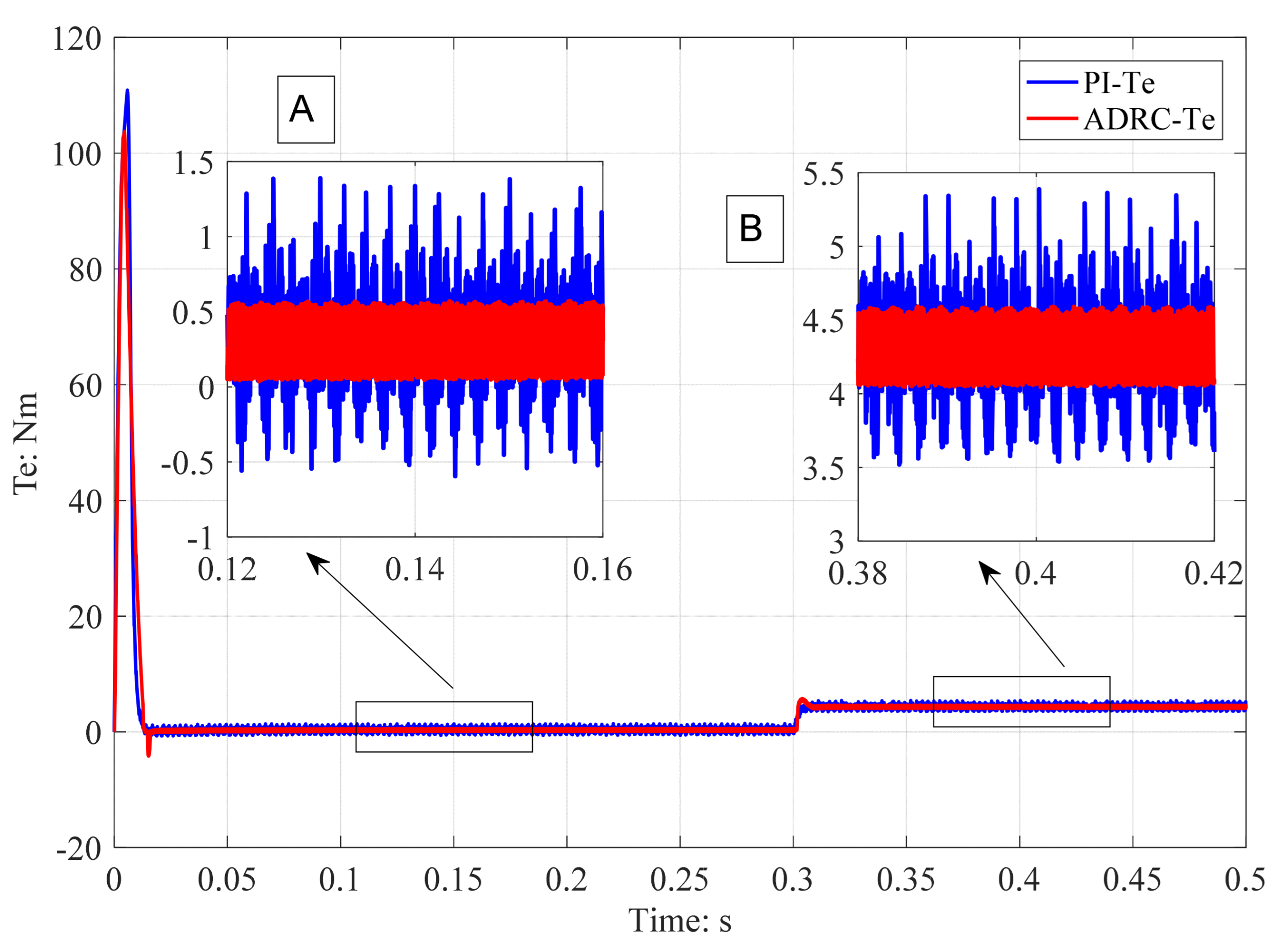
The torque simulation test results for both the PI control mode and the ADRC control mode during speed operation are displayed in Figure 13. The locally enlarged figure A in the Figure 13 represents the torque variation curve under no-load condition. The locally enlarged figure B in the Figure 13 represents the torque variation curve under load conditions.
Figure 13 clearly shows that during the no-load process, at the specified target speed, the torques of both the PI control and ADRC control systems exhibit rapid increases. As the torque increases from 0 to its peak value, the PMSM accelerates at a gradually increasing rate. Upon reaching the peak torque, it steadily decreases, and as the torque diminishes from its peak back to 0, the PMSM experiences an acceleration characterized by gradually diminishing acceleration. When the PMSM reaches the target speed and the torque drops to 0, it maintains a constant speed. Examining the magnified view in image A, it becomes apparent that during constant-speed operation before 0.3 s of loading, the torque does not reach 0 due to the necessity of overcoming its inherent frictional damping force. The maximum torque fluctuation for the PI control method is 1.5 Nm, with a minimum value of −0.5 Nm. Conversely, the maximum torque for the ADRC control mode is 0.5 Nm, and the minimum value is 0 Nm. After applying a 4 Nm load at the 0.3 s mark, the PMSM’s electromagnetic torque rapidly adjusts to 4 Nm, serving to counterbalance external loads and maintain the rotor’s rotation at 1000 r/min. In the magnified view presented in image B, the maximum torque for the PI control method is 5.5 Nm, with a minimum of 3.5 Nm. For the ADRC control method, the minimum torque is 4 Nm and the maximum is 4.5 Nm. Notably, the torque fluctuation observed in the ADRC control method is smaller than that in the PI control method.

5.2. Experimental Results

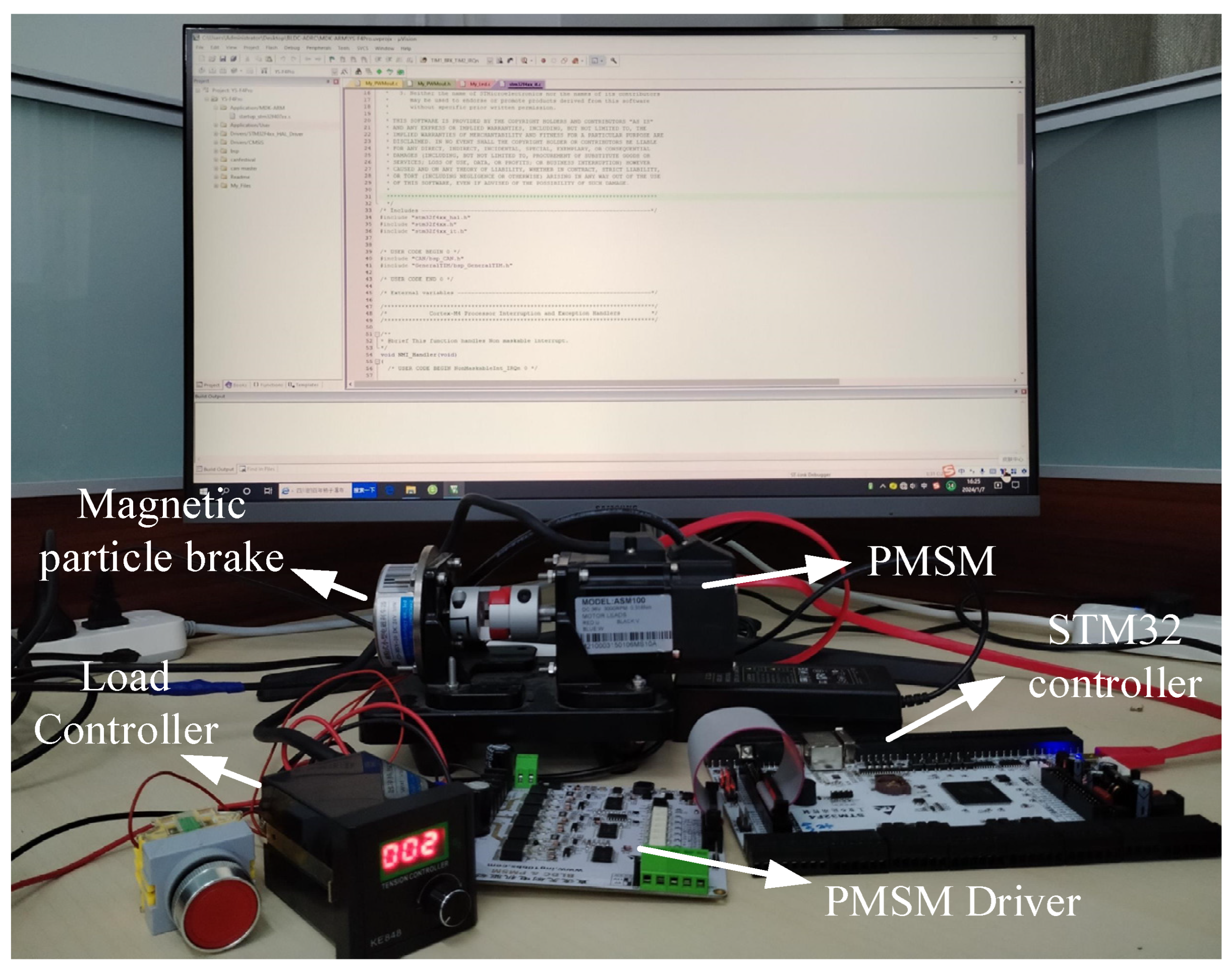
To verify the effectiveness of the proposed sensorless ADRC control method for PMSM based on the Luenberger observer in this paper, we employed the STM32F4 controller. The experimental setup, depicted in Figure 14, was utilized for this purpose. In the course of the experiments, a magnetic powder brake was employed to impart a load onto the PMSM. The essential parameters of the PMSM are detailed in Table 2.
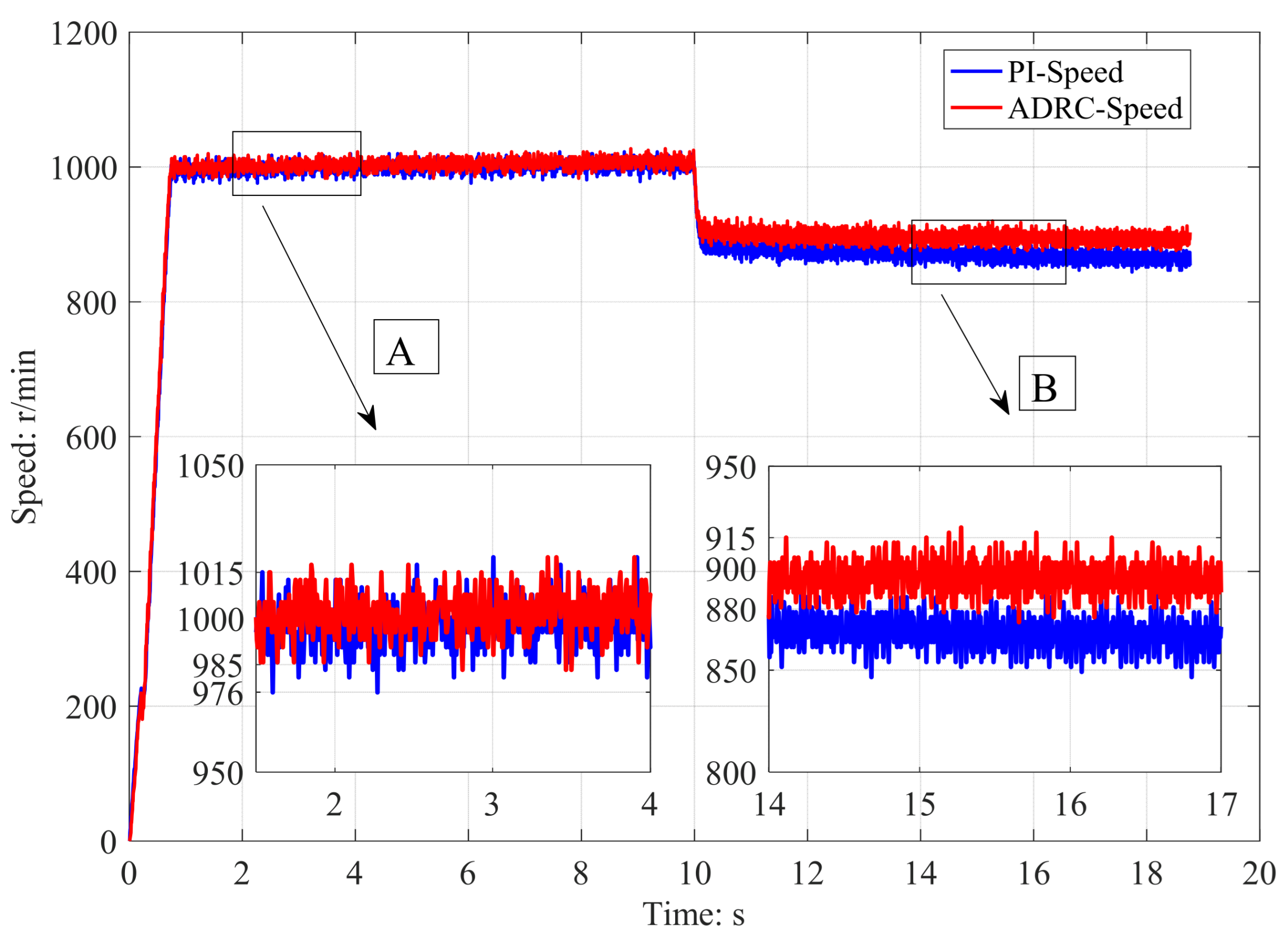
At the starting time, a target speed of 1000 r/min is given, and at 10 s, a load of 0.2 Nm is applied with a speed loop execution frequency of 400 Hz. Figure 15 presents the results of the ADRC control method, which is based on the Luenberger observer, alongside the speed test results for the PI control method, which is also based on the Luenberger observer. The locally enlarged figure A in Figure 15 represents the speed variation curve under no-load conditions. The locally enlarged figure B in Figure 15 represents the speed variation curve under load conditions.
The PI control parameters and the ADRC control parameters are adjusted to achieve the target speed at the same time. From the speed experiment results, it can be concluded that given a speed step signal of 1000 r/min, the times required for both to reach the target speed are the same. A zoomed-in image A shows that during stable operation without loading for 0 to 10 s, the minimum speed fluctuation in the PI control mode is 976 r/min, and the maximum speed fluctuation is 1015 r/min, and the minimum speed fluctuation in the ADRC control mode is 985 r/min, and the maximum speed fluctuation is 1015 r/min. After a 10 s interval, a certain static error becomes evident in both control methods that lack sensors. The ADRC control method, based on the Luenberger observer, exhibits a minimum speed fluctuation of 880 r/min and a maximum of 915 r/min. Similarly, the speed fluctuation of the PI control method, which also utilizes the Luenberger observer, reaches a minimum of 850 r/min and a maximum of 880 r/min. Based on the results of the speed experiment, it can be concluded that when utilizing the Luenberger observer, the ADRC control method demonstrates superior resistance to load disturbances. The ADRC controller enhances the speed control accuracy in sensorless operation with the Luenberger observer, reduces the speed jitter amplitude during sensorless steady-state operation, and enhances the system’s resilience to load disturbances.

6. Conclusions

This article presents an approach to inductive vector ADRC for permanent magnet synchronous motors that relies on the Luenberger observer. It establishes mathematical models for the Luenberger observer and the second-order ADRC, along with deriving the range of error feedback gain required for the Luenberger observer’s convergence. This study conducts a comprehensive analysis of simulation outcomes, including speed, current, and torque, for both the ADRC sensorless control method based on the Luenberger observer and the PI sensorless control method based on the Luenberger observer. Additionally, experimental verification is performed for these two control methods to validate the effectiveness of the proposed control strategy through both simulation and physical testing.
The findings indicate that the ADRC sensorless control method, which relies on the Luenberger observer, enhances the speed control accuracy during sensorless operation, diminishes the speed jitter amplitude in sensorless steady-state operation, and increases the system’s resilience to load disturbances.

Author Contributions

Conceptualization, P.Z.; methodology, P.Z., B.Y. and H.Q.; software, P.Z.; validation, P.Z. and H.Q.; formal analysis, P.Z.; investigation, H.Q.; resources, Z.S.; data curation, P.Z.; writing—original draft preparation, P.Z.; writing—review and editing, P.Z. and B.Y.; visualization, P.Z. and H.Q.; supervision, H.Q.; project administration, Z.S.; funding acquisition, Z.S. All authors have read and agreed to the published version of the manuscript.

Funding

This research was funded by the National Natural Science Foundation of China Youth Fund (Granted No. 52305046).

Data Availability Statement

Data are contained within the article.

Conflicts of Interest

The authors declare no conflict of interest.

References

  1. Lu, H.; Li, S. Speed control for PMSM servo system using predictive functional control and extended state observer. IEEE Trans. Ind. Electron. 2011, 59, 1171–1183. [Google Scholar] [CrossRef]
  2. Ahn, H.; Park, H.; Kim, C.; Lee, H. A Review of State-of-the-art Techniques for PMSM Parameter Identification. J. Electr. Eng. Technol. 2020, 15, 1177–1187. [Google Scholar] [CrossRef]
  3. Ullah, K.; Guzinski, J.; Mirza, A.F. Critical review on robust speed control techniques for permanent magnet synchronous motor (PMSM) speed regulation. Energies 2022, 15, 1235. [Google Scholar] [CrossRef]
  4. Niu, S.; Luo, Y.; Fu, W.; Zhang, X. Robust model predictive control for a three-phase PMSM motor with improved control precision. IEEE Trans. Ind. Electron. 2020, 68, 838–849. [Google Scholar] [CrossRef]
  5. Hong, D.-K.; Hwang, W.; Lee, J.-Y.; Woo, B.-C. Design, analysis, and experimental validation of a permanent magnet synchronous motor for articulated robot applications. IEEE Trans. Magn. 2017, 54, 1–4. [Google Scholar] [CrossRef]
  6. Vafaie, M.H.; Dehkordi, B.M.; Moallem, P.; Kiyoumarsi, A. A new predictive direct torque control method for improving both steady-state and transient-state operations of the PMSM. IEEE Trans. Power Electron. 2015, 31, 3738–3753. [Google Scholar] [CrossRef]
  7. Wang, Q.; Wang, S.; Chen, C. Review of sensorless control techniques for PMSM drives. IEEJ Trans. Electr. Electron. Eng. 2019, 14, 1543–1552. [Google Scholar] [CrossRef]
  8. Kim, H.; Son, J.; Lee, J. A High-Speed Sliding-Mode Observer for the Sensorless Speed Control of a PMSM. IEEE Trans. Onindustrial Electron. 2011, 58, 4069. [Google Scholar]
  9. Abdelrahem, M.; Hackl, C.M.; Kennel, R. Finite Position Set-Phase Locked Loop for Sensorless Control of Direct-Driven Permanent-Magnet Synchronous Generators. IEEE Trans. Power Electron. 2018, 33, 3097. [Google Scholar] [CrossRef]
  10. Yang, H.; Xu, A.; Zhang, Y.; Chai, X. Error Analysis and Design of Sliding Mode Observer-based Sensorless PMSM Drives under Low Sampling Ratio. IEEE Trans. Power Electron. 2024. [Google Scholar] [CrossRef]
  11. Li, Y.; Hu, H.; Shi, P. A Review of Position Sensorless Compound Control for PMSM Drives. World Electr. Veh. J. 2023, 14, 34. [Google Scholar] [CrossRef]
  12. Benchabane, F.; Titaouine, A.; Bennis, O.; Yahia, K.; Taibi, D. Sensorless fuzzy sliding mode control for permanent magnet synchronous motor fed by AC/DC/AC converter. Int. J. Syst. Assur. Eng. Manag. 2012, 3, 221–229. [Google Scholar] [CrossRef]
  13. Teymoori, V.; Kamper, M.; Wang, R.-J.; Kennel, R. Sensorless control of dual three-phase permanent magnet synchronous machines—A review. Energies 2023, 16, 1326. [Google Scholar] [CrossRef]
  14. Quang, N.K.; Hieu, N.T.; Ha, Q.P. FPGA-based sensorless PMSM speed control using reduced-order extended Kalman filters. IEEE Trans. Ind. Electron. 2014, 61, 6574–6582. [Google Scholar] [CrossRef]
  15. Liang, D.; Li, J.; Qu, R. Sensorless control of permanent magnet synchronous machine based on second-order sliding-mode observer with online resistance estimation. IEEE Trans. Ind. Appl. 2017, 53, 3672–3682. [Google Scholar] [CrossRef]
  16. Qiao, Z.; Shi, T.; Wang, Y.; Yan, Y.; Xia, C.; He, X. New sliding-mode observer for position sensorless control of permanent-magnet synchronous motor. IEEE Trans. Ind. Electron. 2012, 60, 710–719. [Google Scholar] [CrossRef]
  17. Antti, P.; Marko, H. Adaptation of motor parameters in sensorless PMSM drives. IEEE Trans. Ind. Appl. 2009, 45, 203–212. [Google Scholar]
  18. Antti, P.; Jorma, L. Adaptive observer combined with HF signal injection for sensorless control of PMSM drives. In Proceedings of the IEEE International Conference on Electric Machines and Drives, San Antonio, TX, USA, 15 May 2005; pp. 674–681. [Google Scholar]
  19. Faten, G.; Lassaâd, S. Speed sensorless IFOC of PMSM based on adaptive Luenberger observer. Int. J. Electr. Electron. Eng. 2009, 2, 7–13. [Google Scholar]
  20. Huang, X.; Guan, P.; Pan, H.; Liu, S.; Du, G.; Huang, X.; Wang, X. Research on grey predictive control of PMSM based on reduced-order luenberger observer. J. Electr. Eng. Technol. 2021, 16, 2635–2646. [Google Scholar] [CrossRef]
  21. Wang, B.; Tian, M.; Yu, Y.; Dong, Q.; Xu, D. Enhanced ADRC with quasi-resonant control for PMSM speed regulation considering aperiodic and periodic disturbances. IEEE Trans. Transp. Electrif. 2021, 8, 3568–3577. [Google Scholar] [CrossRef]
  22. Zhao, Y.; Dong, L. Robust current and speed control of a permanent magnet synchronous motor using SMC and ADRC. Control Theory Technol. 2019, 17, 190–199. [Google Scholar] [CrossRef]
  23. Lu, W.; Li, Q.; Lu, K.; Lu, Y.; Guo, L.; Yan, W.; Xu, F. Load adaptive PMSM drive system based on an improved ADRC for manipulator joint. IEEE Access 2021, 9, 33369–33384. [Google Scholar] [CrossRef]
  24. Tian, M.; Wang, B.; Yu, Y.; Dong, Q.; Xu, D. Discrete-time repetitive control-based ADRC for current loop disturbances suppression of PMSM drives. IEEE Trans. Ind. Inform. 2021, 18, 3138–3149. [Google Scholar] [CrossRef]
  25. Ahcene, F.; Bentarzi, H. Synthesis of ADRC and its Application to an Electrical Power System. Alger. J. Signals Syst. 2022, 7, 122–134. [Google Scholar] [CrossRef]
  26. Ma, Z.; Liu, G.; Liu, Y.; Yang, Z.; Zhu, H. Research of a six-pole active magnetic bearing system based on a fuzzy active controller. Electronics 2022, 11, 1723. [Google Scholar] [CrossRef]
  27. Tao, L.; Chen, Q.; Nan, Y.; Dong, F.; Jin, Y. Speed tracking and synchronization of a multimotor system based on fuzzy ADRC and enhanced adjacent coupling scheme. Complexity 2018, 2018, 5632939. [Google Scholar] [CrossRef]
  28. Su, G. Fuzzy ADRC controller design for PMSM speed regulation system. Adv. Mater. Res. 2011, 201, 2405–2408. [Google Scholar] [CrossRef]
  29. Li, J.; Ren, H.; Zhong, Y. Robust speed control of induction motor drives using first-order autodisturbance rejection controllers. IEEE. Trans. Ind. Appl. 2015, 51, 712–720. [Google Scholar] [CrossRef]
  30. Han, J. From PID to active disturbance rejection control. IEEE Trans. Ind. Electron. 2009, 56, 900–906. [Google Scholar] [CrossRef]
Figure 1. PMSM Luenberger observer model.
Processes 12 00906 g001
Figure 2. Structural diagram of the PLL.
Processes 12 00906 g002
Figure 3. Structural block diagram of the PLL.
Processes 12 00906 g003
Figure 4. The structural diagram of ADRC.
Processes 12 00906 g004
Figure 5. Block diagram of the sensorless ADRC for the Luenberger observer.
Processes 12 00906 g005
Figure 6. ADRC simulation module.
Processes 12 00906 g006
Figure 7. PMSM simulation module based on FOC.
Processes 12 00906 g007
Figure 8. Luenberger observer module.
Processes 12 00906 g008
Figure 9. Speed step response results.
Processes 12 00906 g009
Figure 10. Speed error variation curve.
Processes 12 00906 g010
Figure 11. Three-phase current variation curve of the PI control method.
Processes 12 00906 g011
Figure 12. Three-phase current variation curve of the ADRC control mode.
Processes 12 00906 g012
Figure 13. Torque variation curve.
Processes 12 00906 g013
Figure 14. Experimental testing system.
Processes 12 00906 g014
Figure 15. Speed test results.
Processes 12 00906 g015
Table 1. Simulation process parameter table.
ParameterValueParameterValue
Luenberger−K1155,000ADRC−β1250
Luenberger−K2140,000ADRC−β21.2
ADRC−r0.1ADRC−β012000
ADRC−h0.25ADRC−β022100
ADRC−α10.5ADRC−β032400
ADRC−α20.75PI−kp/ki0.4/0.02
Table 2. Basic Experimental Parameters.
NameValueUnit
Maximum speed5000r/min
Rated voltage24V
Rated torque0.318Nm
Rated current4.6A
Moment of inertia0.0588kg·m2 10−4
Line resistance0.75Ω
Weight0.8kg
Disclaimer/Publisher’s Note: The statements, opinions and data contained in all publications are solely those of the individual author(s) and contributor(s) and not of MDPI and/or the editor(s). MDPI and/or the editor(s) disclaim responsibility for any injury to people or property resulting from any ideas, methods, instructions or products referred to in the content.