Article

Study on the Deactivation Mechanism of Ru/C Catalysts

China Institute of Atomic Energy, Beijing 102413, China
*
Authors to whom correspondence should be addressed.
Processes 2024, 12(6), 1138; https://doi.org/10.3390/pr12061138
Submission received: 4 May 2024 / Revised: 20 May 2024 / Accepted: 22 May 2024 / Published: 31 May 2024
(This article belongs to the Section Catalysis Enhanced Processes)

Abstract

:
Employing catalytic decomposition to break down reducing agents in intermediate-level radioactive waste during nuclear fuel reprocessing offers significant advantages. This study focuses on investigating the deactivation behavior of 5% Ru/C catalysts by two different synthesis processes used for reducing agent destruction. Deactivation experiments were conducted by subjecting the 5% Ru/C catalysts to 100 and 150 reaction cycles. Changes in the concentration of free radicals on the carbon-based carrier were measured to analyze the loading position and loss of Ru ions. Additionally, sorption–desorption curves and pore size distributions of the four catalysts were obtained. Analysis results reveal that Ru ions on the catalyst adsorb onto active free radical sites on the carbon-based carrier. Under ultrasonic conditions, some Ru ions partially desorb from the free radical sites on the carbon-based carrier, and desorbed Ru ions may adsorb onto weak free radical sites, while undesorbed Ru ions may adsorb onto strong free radical sites. After hundreds of hours of reaction, SM1 and SM2 exhibited approximately a 30% decrease in specific surface area and pore volume compared to SM0. However, the catalyst activity remained unchanged, and the catalyst pore size remained essentially unchanged, which primarily means that the micropores on the catalyst’s surface have undergone corrosion and damage.

1. Introduction

Nuclear fuel reprocessing entails the extraction and recovery of valuable elements from spent fuel within reactors [1,2,3,4]. Its primary procedures encompass cutting the fuel into short segments, dissolving it in nitric acid, and employing chemical extraction methods [5,6,7]. During the chemical extraction phase, a technique involving the introduction of a reducing back-extractant is utilized to modulate the valence state of plutonium in the solution. This adjustment serves to regulate the distribution ratio of plutonium in the oil–water solution, facilitating the separation and extraction of uranium and plutonium. However, the crude product 1BP solution obtained from the co-decontamination separation cycle contains Pu(III) and residual reducing agents. Before entering the plutonium purification cycle, it is essential to first adjust the valence state and acidity. This adjustment is necessary to prepare the solution (2AF) for the purification cycle [8,9]. During this process, it is crucial to eliminate any remaining reducing agents in 1BP and convert Pu(III) to Pu(IV). Similarly, the Pu product solution 2BP obtained from the plutonium purification cycle also contains Pu(III) and residual reducing agents. Hence, it requires oxidation of both the reducing agents and Pu(III), followed by acid adjustment, before proceeding to the oxalate precipitation process. The precipitated Pu oxalate is then calcined to produce PuO2 [10,11,12].
Additionally, the aqueous waste 2DW from the uranium purification cycle, classified as intermediate-level waste, needs evaporation, concentration, and denitrification treatment. However, the presence of residual reducing agents in 2DW during the chemical denitrification process can lead to severe consequences such as radioactive contamination in condensate and potential explosions [13,14]. Therefore, before undergoing evaporation and concentration, 2DW should undergo a process to neutralize the reducing agents [15].
In the early stages of reprocessing, sodium nitrite (NaNO2) is commonly employed to adjust the valence state of plutonium [8,16]. This compound facilitates the rapid conversion of plutonium from its trivalent to tetravalent state within minutes. Even after the reducing agent and its supporting reagents are depleted, sodium nitrite can continue to oxidize plutonium(III) to plutonium(IV). The advantages of using sodium nitrite for valence adjustment are manifold: it boasts a swift reaction rate, ensures operational safety, requires minimal complexity in handling, and comes at a low cost. However, there are drawbacks to consider. Excessive sodium nitrite is susceptible to extraction by tributyl phosphate (TBP), leading to the degradation of organic solvents and hindering the efficient stripping of Pu(IV) post-extraction. Additionally, the introduction of sodium ions into the system elevates the salinity of the waste solution. It is estimated that due to these factors, every ton of produced plutonium results in approximately seven tons of sodium nitrate α waste, substantially augmenting the burden of storing and treating radioactive waste. Consequently, various nations have embarked on the development of “salt-free” valence adjustment technologies, including the nitrogen oxide (nitrous gas) method [17], liquid N2O4 method [18], electrochemical method [19,20,21], and Pt-catalyzed oxidation method [22], among others.
Since the late 1990s, scholars from Russia and France have contributed extensively to the literature on Pt-catalyzed oxidation or reduction [23,24,25,26,27,28,29]. This catalytic oxidation method achieves the dual objectives of reducing agent degradation and Pu valence adjustment through the catalyst’s activity. Notably, it introduces no additional ions, marking a significant advancement in salt-free oxidation-reduction techniques. In 2000, during the “Full-flow Bench Scale Test of Power Reactor Spent Fuel Reprocessing” conducted by the China Institute of Atomic Energy, a breakthrough was made. Utilizing a bespoke small-scale Pt catalytic device, researchers successfully achieved the catalytic oxidation valence adjustment of Pu(III) in a 7 mol/L HNO3 solution, without the need for additional chemical reagents, by employing retained 3BP solution [30]. Following this milestone, China Institute of Atomic Energy delved deeper into catalytic decomposition. They explored Pt’s catalytic role in decomposing reducing agents such as hydroxylamine, hydrazine, dimethylhydroxylamine, and methylhydrazine, alongside Pt-catalyzed oxidation valence adjustment of Pu in a nitric acid medium. The results revealed Pt’s significant catalytic prowess in both reducing agent decomposition and Pu(III) oxidation valence adjustment. These findings portend promising applications of catalytic decomposition techniques within the Purex process [30].
In recent years, the China Institute of Atomic Energy has designed and developed Ru/C catalysts and catalytic decomposition processes for the “nitric acid hydroxylamine-nitric acid hydrazine” system [31,32]. In this system, aqueous waste containing reducing agents undergoes full decomposition upon contact with the catalyst, yielding nitrogen oxides, nitrogen gas, water, and small amounts of ammonia, effectively achieving removal objectives. This method presents several advantages over the nitrogen oxide oxidation approach: (1) Simplified equipment system composition reduces the need for nitrogen oxide preparation and transportation systems. (2) The treatment process eliminates the requirement for introducing chemical reagents. (3) Overall process operation is convenient, requiring only control of the flow rate and temperature of the 2DW solution, facilitating unmanned operation. (4) Significant reduction in waste liquid and gas volume minimizes excess nitrogen oxides entering the exhaust gas and the generation of high-acid salt waste liquid during nitrogen oxide preparation. (5) Enhanced cost-effectiveness due to reduced reliance on chemical reagents for nitrogen oxide preparation, as well as reduced expenses for personnel, equipment maintenance, and waste treatment. The catalytic decomposition process offers significant advantages in safety, cost-effectiveness, and environmental friendliness compared to traditional methods, showing promising prospects for widespread application [33].
To realize the industrial application of this catalyst, understanding its deactivation mechanism is essential. Previous research on the deactivation mechanisms of hydrazine decomposition catalysts has primarily focused on factors such as chemical degradation, leading to a reduction in catalyst activity. J. P. Contour [34] utilized infrared spectroscopy to investigate catalysts after hydrazine decomposition reactions. They discovered that atomic-state nitrogen strongly adsorbs onto the catalyst surface, occupying metal sites and consequently reducing the active surface area of the catalyst, leading to decreased activity. Additionally, the loss of surface chlorine on the catalyst is considered a significant cause of deactivation in hydrazine decomposition catalysts. Hydrazine decomposition is an exothermic reaction, with the catalyst bed reaching temperatures as high as 1200 K under steady-state conditions. For metal catalysts with high loadings, the reduction in active surface area due to high-temperature sintering also contributes to catalyst deactivation.
S. Mary [35] investigated the impact of chlorine content in iridium catalysts on their performance during aging. They found that removing surface chlorine ions from the catalyst can enhance its stability in water vapor treatment without significantly affecting metal dispersion or catalytic activity. However, the aggregation of small iridium grains or the transformation of iridium into mobile oxygen–chlorine surface compounds during catalyst aging can lead to decreased catalytic activity.
Research on the potential mechanisms of deactivation in supported catalysts has received considerable attention [36,37,38,39,40]. It primarily stems from changes in the catalyst’s physical structure, active components, and auxiliary components due to chemical reactions or phase transitions [41,42,43,44,45,46]. The China Institute of Atomic Energy has developed a process utilizing small organic molecules as reducing agents. In this process, the nitric acid solution containing dimethylhydroxylamine (DMHAN) and monomethylhydrazine (MMH) as reducing agents undergoes catalytic decomposition before entering the next process unit. The catalytic decomposition process predominantly employs a Ru/C catalyst system. This paper primarily investigates the deactivation mechanism of the Ru/C catalyst during this process.
The study conducted deactivation experiments using two kinds of 5% Ru/C catalysts which are prepared by different synthesis processes. After 100 and 150 reaction cycles, changes in the concentration of free radicals on the carbon-based carrier were measured to analyze the loading position and loss of Ru ions. Additionally, the specific surface area, average pore diameter, and pore volume of the four catalysts were analyzed.

2. Experimental Methods and Materials

2.1. The Synthesis Method of the Catalyst Used in This Paper

The preparation of ruthenium-supported catalysts was carried out using two distinct particle size activated carbon supports through the conventional impregnation-reduction method. The sizes of the two types of activated carbon carriers were 4–8 mesh and 10–20 mesh, respectively. Hydrated ruthenium trichloride (RuCl3·3H2O) was used as the precursor for ruthenium. In a typical process, the activated carbon was added into the hydrated ruthenium trichloride aqueous solution, stirred at room temperature for 12 h, dried by vacuum distillation at 50 °C in a round-bottom flask, and then kept at 110 °C for 12 h in an oven. The resulting solid was reduced by H2 (heating rate of 5 °C/min and flow rate of 60 mL/min) at 350 °C for 2 h. The catalysts, denoted as Ru/C-1 and Ru/C-2, respectively, were loaded with 5 wt% of Ru.

2.2. DMHAN and MMH Concentrations Analysis

The concentrations of DMHAN and MMH were determined using ultraviolet-visible spectrophotometry.
The hydroxylamine exhibits the ability to effectively reduce Fe3+ ions to Fe2+ ions in solution. In a pH range of 2–9, o-phenanthrene undergoes a color reaction with Fe2+ ions. This reaction demonstrates remarkable selectivity and yields a highly stable orange-red complex, exhibiting maximum absorption at 510 nm. By utilizing this color reaction, trace amounts of DMHAN can be accurately quantified through spectrophotometry.
Under acidic conditions, hydrazine undergoes a color reaction with p-dimethylaminobenzaldehyde. The absorbance is measured at 457 nm. The concentration of hydrazine exhibits proportionality to the measured absorbance within a specific range, thereby enabling accurate determination of its concentration.

2.3. The Catalyst Treatment Process

The reaction will employ the 5% Ru/C catalyst synthesized in Section 2.1. Reaction conditions include a temperature of 80 °C, a solid-to-liquid ratio of 1:20, and a test solution composed of 0.1 mol/L DMHAN, 0.1 mol/L MMH, and 1 mol/L HNO3. Each reaction cycle is deemed complete when the concentrations of DMHAN and MMH in the feed are below 0.01 mol/L. The DMHAN and MMH concentrations analysis is presented in Section 2.2. After the reaction was completed, the catalyst was separated from the reaction mixture by simple filtration and then reused directly in model reaction for the next round without further purification. Subsequently, the test solution was replaced with fresh solution for successive catalytic reactions, repeating this process iteratively. The catalyst reaction setup is depicted in Figure 1, and the sample designations post-treatment are listed in Table 1.

2.4. Characterization of Catalyst

The specific surface areas of the prepared materials were determined by N2 physical adsorption at 77 K, following the degassing of the samples using a Micromeritics Model ASAP 2010 instrument. The specific surface area of the sample was measured employing the BET method. The morphology of activated carbon and Ru/AC catalysts was visualized with a scanning electron microscope (SEM, PHENOM PHAROS G2, Holland) and transmission electron microscope (TEM, JEOL JEM-F200, Japan) after pulverizing them into powders finer than 200 mesh. Inductively coupled plasma atomic emission spectroscopy (ICP-AES, Thermo ICAT6000, Americ) was employed to measure the actual content of Ru in the catalysts.

2.5. Ru Concentrations Analysis

The determination method for the Ru content in catalysts using ICP-AES is as follows. Take an appropriate amount of catalyst sample in a crucible and heat it at 420 °C for 3 h, followed by cooling to room temperature using a dryer. Subsequently, grind the sample to achieve particle size below 200 mesh. Employing the aqua regia system, dissolve the sample at 200 °C for 30 min utilizing a microwave digestion instrument (CEM MARS6), America, and subsequently determine the Ru content through ICP-AES(Thermo ICAT6000, Americ) analysis.

2.6. Experiment to Determine the Types of Free Radical Sites on Carbon-Based Supports

The primary cause of catalyst activity loss stems from the ineffective bonding of metal ions with the active sites on carbon-based supports, leading to reduced stability. Functional groups and defect sites on carbon-based supports are commonly identified as active sites. These defect sites, existing in an electron-deficient state, have the ability to alter the distribution of active metal electron clouds, thereby strengthening the interaction between the carbon-based support and the metal active phase. Referred to as free radical sites, these defect sites can be analyzed to determine the loading position and loss of Ru ions by measuring changes in the concentration of free radicals on the carbon-based supports.
To ascertain the types of free radical sites on carbon-based supports, the following experimental approach is proposed: Fresh carbon-based supports without Ru ion loading are exposed to pure oxygen. Given that oxygen molecules themselves are free radicals, they can combine with the free radical sites on the carbon-based supports, resulting in a reduction in free radical concentration. Subsequently, nitrogen gas is introduced to displace oxygen molecules, facilitating the separation of free radicals from oxygen molecules on the carbon-based supports. Analysis of the fluctuation in free radical concentration throughout this process aids in identifying the types of free radical sites present on the catalyst.

2.7. Ultrasound Experiment

Similar to the experimental design described above, this study proposes subjecting catalysts loaded with Ru ions to ultrasound treatment, comparing changes in free radical concentration before and after ultrasound treatment. This approach indirectly assesses the impact of Ru ion loss on catalyst activity. The experimental design concept is illustrated in Figure 2.
The catalyst’s ultrasound treatment is conducted at room temperature. Initially, the carbon-based support catalyst loaded with Ru ions is immersed in water. Following a 30 min ultrasound treatment, the catalyst is dried to eliminate moisture, enabling a comparison of free radical concentrations before and after ultrasound exposure.
Free radical analysis is performed using the the electron paramagnetic resonance spectrometer(ESR, Bruker JES-FA200, German). The specific testing parameters include a microwave frequency of 9.5 GHz, a microwave power of 1.578 mW, a central magnetic field of 337 mT, a scanning time of 1 min, and a time constant of 0.03 s. The concentration of free radicals on the carbon-based support is calibrated using 1,1-diphenyl-2-picrylhydrazyl (DPPH) with a known free radical concentration. The free radical concentration (CR) per unit mass of the carbon-based support sample is calculated using Equations (1) and (2), where CR,DPPH denotes the known concentration of DPPH free radicals, DDPPH and Dsample represent the number of free radicals determined by ESR, and msample represents the mass of the sample.
CR = CR,sample/msample
CR,sample/Dsample = CR,DPPH/DDPPH

3. Results and Discussion

3.1. Analysis of Free Radical Site Types

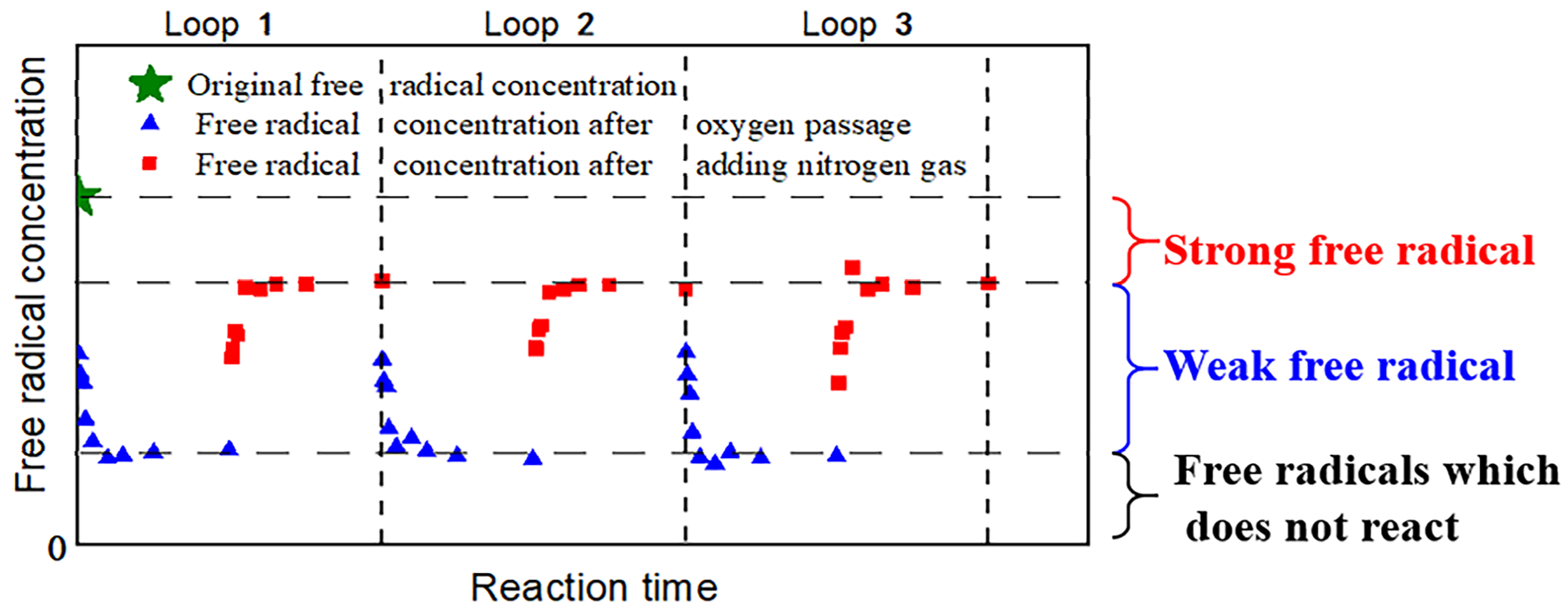
After introducing pure oxygen into fresh carbon-based supports without loaded Ru ions, the concentration of free radicals on the carbon-based supports increases, as illustrated in Figure 3. It can be observed from the graph that even after replacing the adsorbed oxygen with nitrogen gas, the concentration of free radicals on the carbon-based supports does not return to the level observed with fresh carbon-based supports. Based on this observation, the free radical sites on the carbon-based supports can be classified into three categories: strong free radicals, weak free radicals, and non-reactive free radicals. Strong free radical sites can firmly bind with oxygen, weak free radical sites can bind with oxygen but are prone to loss, and non-reactive free radical sites cannot bind with oxygen.
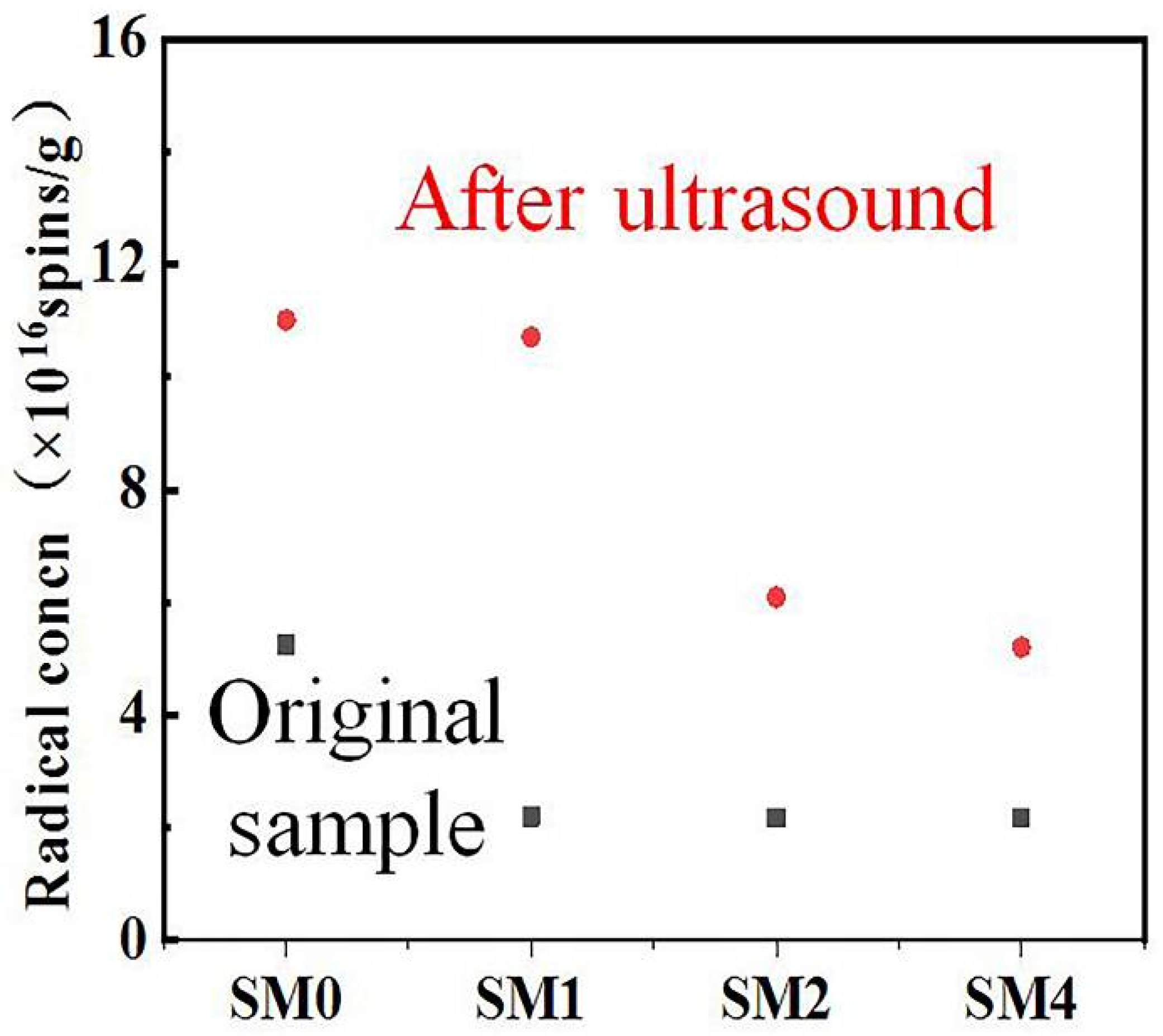
Figure 4 depicts the changes in free radical concentration for four catalyst samples before and after ultrasound treatment. It is evident from the graph that all four catalysts show varying degrees of increase in free radical concentration after ultrasound treatment. This suggests several points: (1) Ru ions on the catalysts adsorb onto the free radical active sites of the carbon-based support, (2) under ultrasound conditions, some Ru ions desorb from the free radical sites on the carbon-based support, and (3) desorbed Ru ions may adsorb onto weak free radical sites, while those remaining adsorbed may occupy strong free radical sites. Previous studies suggest that the strong free radical sites form pseudo-chemical bonds with Ru ions, which is the primary reason for their firm existence and resistance to desorption.
The two types of activated carbon, 4–8 mesh and 10–20 mesh, were procured from different manufacturers, leading to variations in their adsorption capacity for Ru due to disparities in structural properties and chemical composition. As depicted in Figure 4, SM4 exhibited a lower number of free radical sites following ultrasound treatment, which can be attributed to the differential adsorption capacity of activated carbon for Ru rather than the particle size of the activated carbon.
Figure 4 indicates that following ultrasound treatment, the catalyst’s free radical concentration rose from its original level of 2.1 × 10¹⁶ spins/g to 5.1 × 10¹⁶ spins/g, marking an increase of 3.0 × 10¹⁶ spins/g. This suggests that 2.57% of Ru which desorbed under ultrasound conditions is distributed across 3.0 × 10¹⁶ spins/g of free radical sites on the catalyst.

3.2. Scanning Electron Microscope Analysis

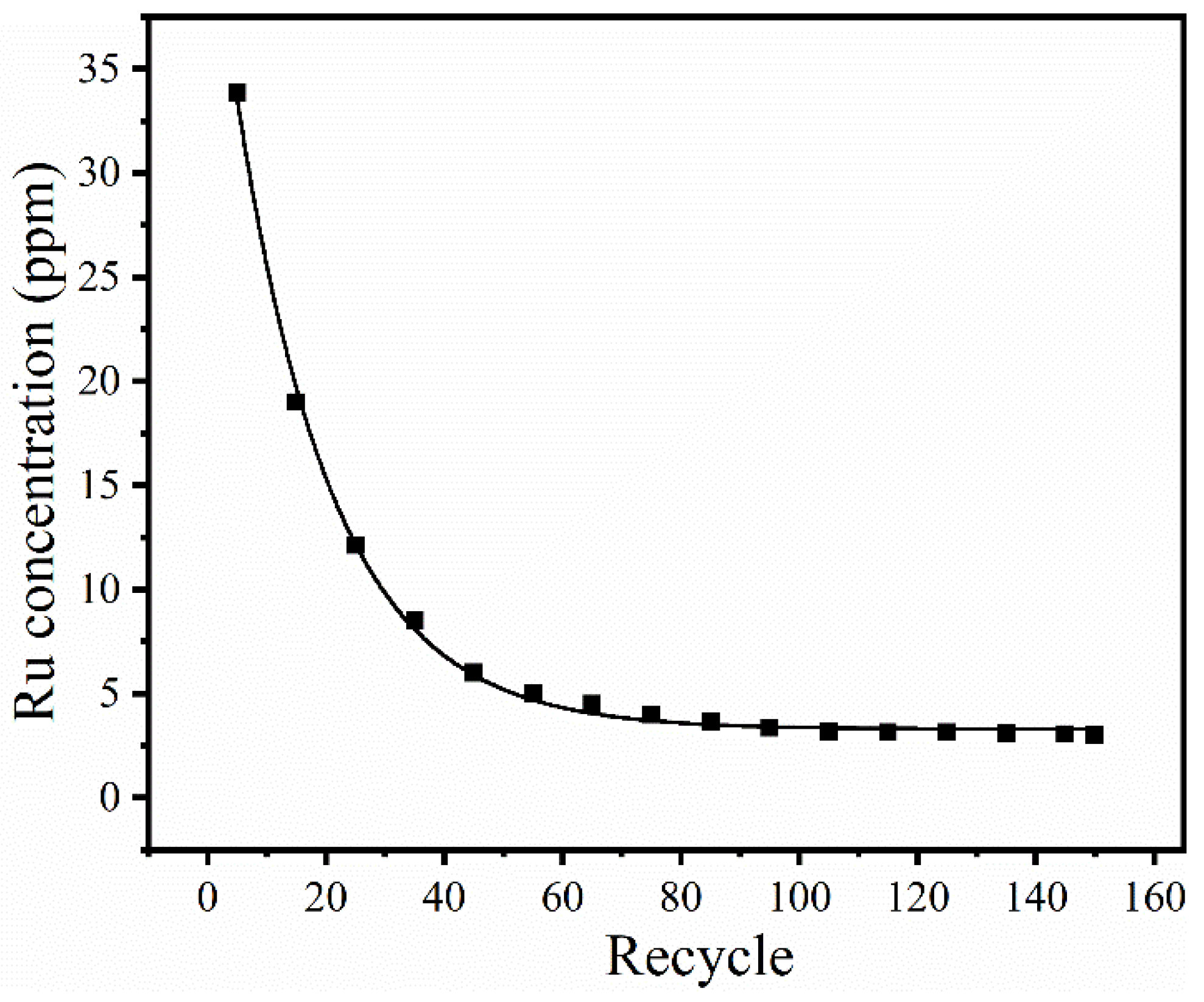
To ascertain the dispersal characteristics of Ru ions, scanning electron microscope (SEM) analysis was employed to examine the distribution of Ru on the four catalysts. The findings are depicted in Figure 5. As depicted in Figure 5, SEM mapping images clearly illustrate a significant reduction in Ru particle density for SM1 and SM2 compared to SM0 over time, with SM2 exhibiting the lowest Ru particle density. Furthermore, we employed the ICP-AES method to determine the actual Ru content of the catalysts. The results revealed that SM1 and SM2 had Ru contents of 4.1% and 3.6%, respectively, indicating a noticeable decline in Ru concentration. These results suggest a substantial decline in the loaded Ru on the catalysts during their utilization. To further analyze the Ru loss pattern, the concentration of Ru in the solution after completion of the reaction was measured using the ICP-AES method, as depicted in Figure 6. In the initial stages of the cycle, a substantial loss of Ru occurs primarily due to inadequate adsorption of large Ru particles on the catalyst surface. With an increasing number of uses, the concentration of Ru gradually decreased and reached equilibrium in the solution. These findings also validate that there is a loss of Ru during usage, which aligns with observations made through SEM and TEM techniques.
To ascertain the distribution of Ru ions on the carbon-based support, transmission electron microscope (TEM) analysis was performed on the catalyst, using SM4 as an example. The findings are presented in Figure 7. It is evident from the image that Ru ions are uniformly dispersed on the carbon-based catalyst support, with an average particle size of 4.63 nm.
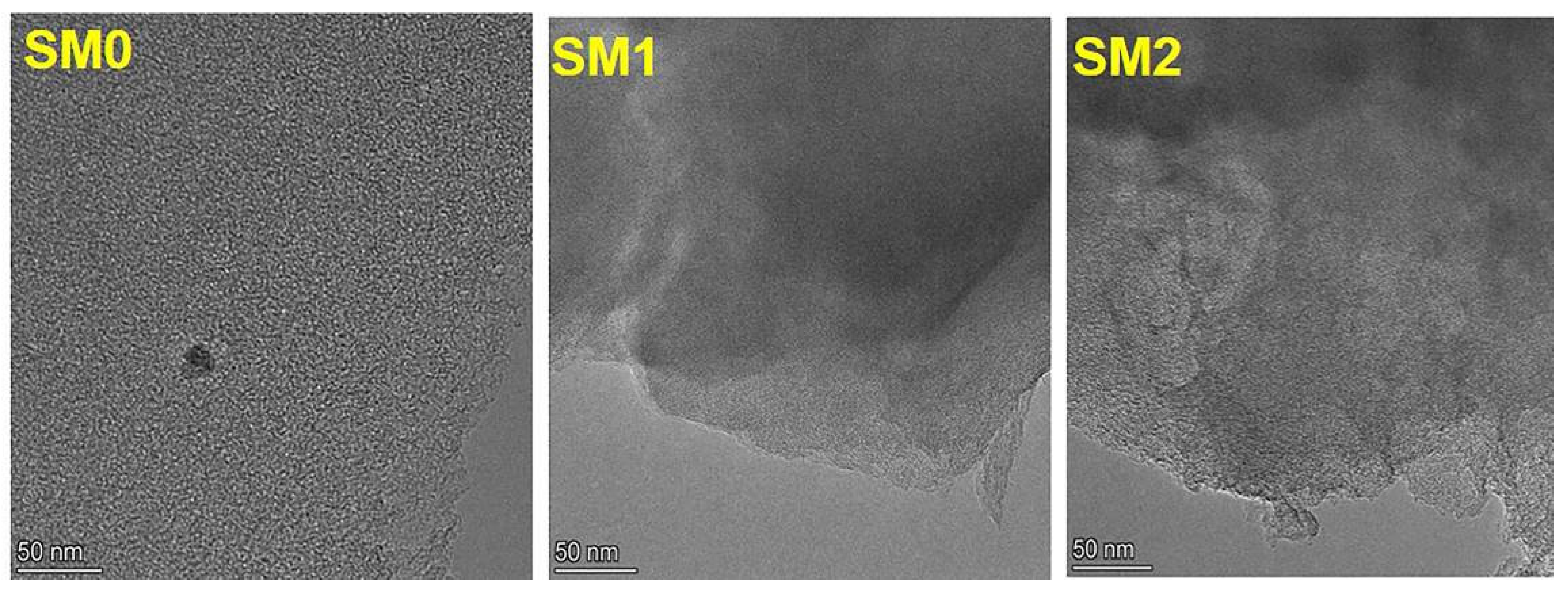
The transmission electron microscope results from Figure 7 and Figure 8 indicate that, following ultrasound treatment, Ru ions are scarcely visible on the carbon-based catalyst support of SM1 and SM2.

3.3. Analysis of Activity and Pore Structure

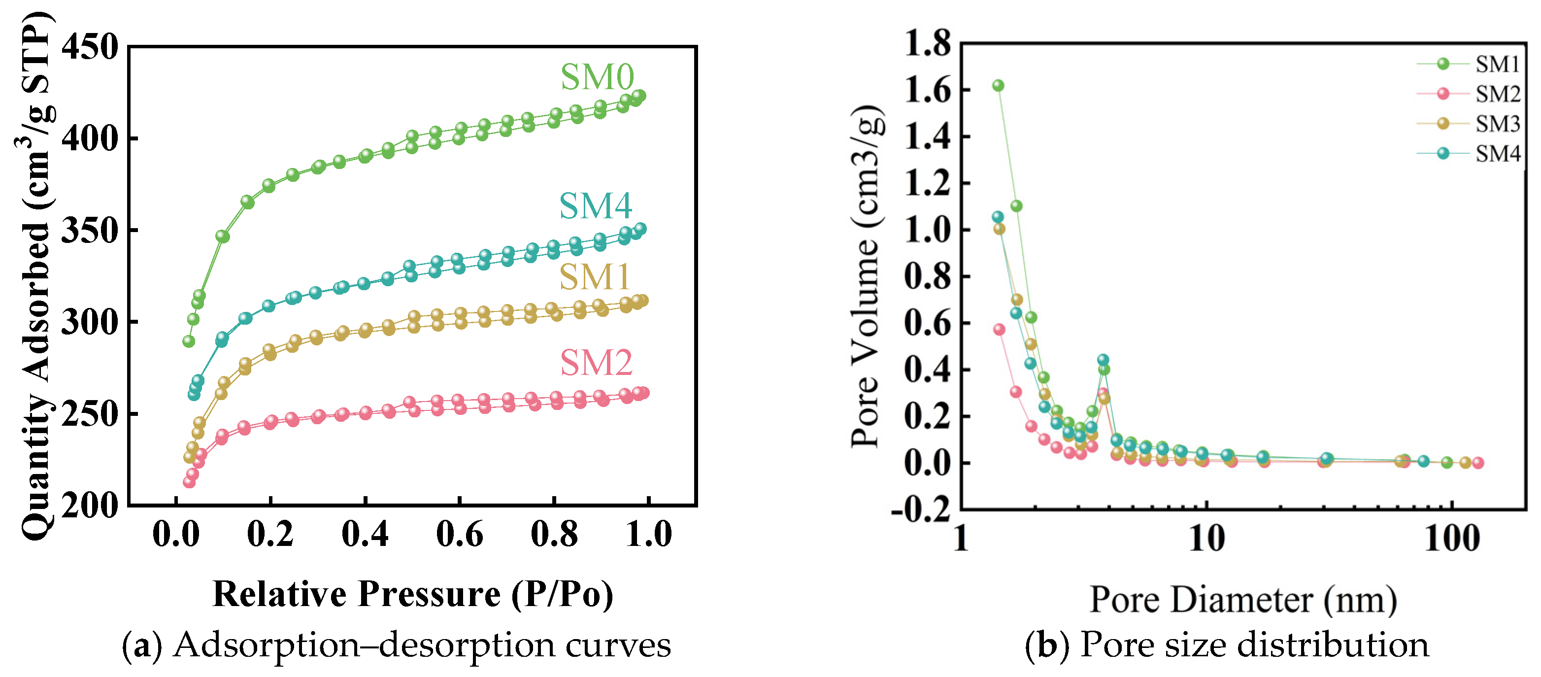
Analyzing changes in pore structure before and after catalyst deactivation can help assess whether the pores of the carbon-based support are blocked or if the support structure has collapsed. Figure 9 presents the sorption–desorption curves and pore size distribution of the four catalysts. The shape of the adsorption curve indicates that all four catalysts exhibit Type I adsorption with a H4 type hysteresis loop, typical for solids containing narrow slit pores similar to those found in activated carbon. The pore size distribution shown in the right panel of Figure 8 reveals that the carbon-based supports of all four catalysts possess a microporous structure.
Table 2 presents a summary of the specific surface area, average pore diameter, and pore volume parameters for the four catalysts obtained from multiple measurements. It is evident from the table that all four catalysts exhibit high specific surface areas and well-developed porous structures. SM1 and SM2 represent catalysts tested after several hundred hours of reaction. It is evident that with increasing usage time, the catalyst’s specific surface area decreases while the average pore size and pore volume remain relatively unchanged. This observation primarily suggests that the micropores on the catalyst’s surface have undergone corrosion and damage, without any discernible alteration in the distribution of internal micropores. SM4, a modified catalyst based on SM0, also shows a minor reduction in specific surface area and pore volume post-modification, while the average pore diameter remains relatively stable.

4. Summary

This study conducted deactivation experiments using the prepared 5% Ru/C catalyst. By subjecting the 5% Ru/C catalyst to 100 and 150 reaction cycles, changes in free radical concentration on the carbon-based support were measured to analyze the loading position and loss of Ru ions. Additionally, sorption–desorption curves and pore size distributions were obtained for the four catalysts. The main conclusions are as follows:
(1)
Ru ions on the catalysts adsorb onto the free radical active sites of the carbon-based support. Under ultrasound conditions, some Ru ions desorb from these sites. Those that desorb may re-adsorb onto weak free radical sites, while those that remain adsorbed may occupy strong free radical sites.
(2)
The adsorption curves of all four catalysts exhibit Type I adsorption with a H4 type hysteresis loop, characteristic of solids containing narrow slit pores, akin to those found in activated carbon.
(3)
After several hundred hours of reaction, SM1 and SM2 experience a slight reduction in specific surface area and pore volume compared to SM0. However, there is no observed change in catalyst activity, and the pore diameter remains largely unchanged. This observation primarily suggests that the micropores on the catalyst’s surface have undergone corrosion and damage, without any discernible alteration in the distribution of internal micropores.

Author Contributions

Validation, X.C.; Data curation, T.L.; Writing—original draft, Z.C.; Writing—review & editing, B.L., C.Z. and W.Z. All authors have read and agreed to the published version of the manuscript.

Funding

This research received no external funding.

Data Availability Statement

The data presented in this study are available on request from the corresponding author.

Conflicts of Interest

The authors declare no conflict of interest.

References

  1. Fishwick, T. The development of conventional safety culture in the nuclear industry. Part 2—Manufacture and reprocessing of nuclear fuel. Loss Prevent. Bull. 2022, 288, 7–12. [Google Scholar]
  2. Boparai, A.S. Gas Chromatographic Analysis of Nuclear Fuel Reprocessing TRUEX-CCI4 Process Solvent. J. Chromatogr. Sci. 1986, 24, 434–437. [Google Scholar] [CrossRef]
  3. NFCC. Status of Nuclear Fuel Reprocessing, Spent Fuel Storage and High-Level Waste Disposal. 1978. Available online: https://www.osti.gov/biblio/5964412 (accessed on 11 January 1978).
  4. Soelberg, N.R.; Garn, T.G.; Greenhalgh, M.R.; Law, J.D.; Jubin, R.; Strachan, D.M.; Thallapally, P.K. Radioactive iodine and krypton control for nuclear fuel reprocessing facilities. Sci. Technol. Nucl. Install. 2013, 2013, 702496. [Google Scholar] [CrossRef]
  5. Li, T.; Liu, F.; Zhou, J.; Zuo, C.; Yan, T.; Zheng, W. Establishment and Verification of the Kinetics Model of Uranium Continuous Dissolution by Using Discrete Element Method. Processes 2023, 11, 2343. [Google Scholar] [CrossRef]
  6. Vance, R.F. Characterization of the Head End Cells at the West Valley Nuclear Fuel Reprocessing Plant; West Valley Nuclear Services Co.: West Valley, NY, USA, 1986. [Google Scholar] [CrossRef]
  7. Liu, H.J.; Wu, H. Numerical Investigation of Uranium Nitrate Atomization Properties during the Nuclear Fuel Reprocessing. Energy Conserv. Technol. 2016, 34, 3–6,12. [Google Scholar] [CrossRef]
  8. Zhang, Z.F.; Wang, J.F.; Zhang, T.X. Power Reactor Nuclear Fuel Reprocessing Technology; China Atomic Energy Press: Beijing, China, 2013. [Google Scholar]
  9. Zhang, H.; Ye, G.A.; Li, L.; Yang, H.; Li, H.R. Preparation of 2AF Solution by Electrochemical Method Ⅱ. Electrooxidation of Pu(Ⅲ) to Prepare 2AF Solution. J. Nucl. Radiochem. 2010, 32, 145–148. [Google Scholar]
  10. Ren, F.Y.; Zhou, Z.X. Foreign Nuclear Fuel Reprocessing; Atomic Energy Press: Beijing, China, 2006. [Google Scholar]
  11. Chang, L.; Tian, B.S.; Li, W.M. Oxidation Decomposition of Hydrazine in Nitric Acid. J. Nucl. Radiochem. 2005, 27, 96–99. [Google Scholar] [CrossRef]
  12. Ren, X.G.; Li, M.H.; Wang, A.Q.; Li, L.; Wang, X.D.; Zhang, T. Catalytic Decomposition of Hydroxyl Ammonium Nitrate at Room Temperature. Chin. J. Catal. 2007, 28, 1–2. [Google Scholar] [CrossRef]
  13. Wei, C.; Saraf, S.R.; Rogers, W.J.; Mannan, M.S. Thermal runaway reaction hazards and mechanisms of hydroxylamine with acid/base contaminants. Thermochim. Acta 2004, 421, 1–9. [Google Scholar] [CrossRef]
  14. Iwata, Y.; Koseki, H. Risk evaluation of decomposition of hydroxylamine/water solution at various concentrations. Process Saf. Prog. 2002, 21, 136–141. [Google Scholar] [CrossRef]
  15. Breschet, C.; Miquel, P. Improvement of the procedure used to treat highly irradiated fuels. In Proceedings of the International Solvent Extraction Conference, Lyon, France, 8–14 September 1974; London Society of Chemical Industry: London, UK, 1971; pp. 565–576. [Google Scholar]
  16. Jiang, S.J.; Ren, F.Y. Nuclear Fuel Reprocessing Technology; Atomic Energy Press: Beijing, China, 1995. [Google Scholar]
  17. Benedict, M. Nuclear Chemical Engineering, 2nd ed.; McCraw-Hill BooK Company: New York, NY, USA, 1981. [Google Scholar]
  18. Hou, X.L.; Zhang, S.Q.; Hu, J.; Wei, X.F.; Zhao, H.G. Study of plutonium valence adjustment in 1AF solution in purex process with nitrogen oxide. Nucl. Sci. Eng. 1995, 15, 165–171. [Google Scholar]
  19. Zhang, S.Q.; Wei, X.F.; Ye, G.A.; Zhang, X.Y.; Zhuang, W.X.; Liu, S.Y.; Fu, L.C. Research on Regulating Plutonium Valence State with N2O4 in Purex Process. Atom. Energy Sci. Technol. 1993, 72, 130–137. [Google Scholar]
  20. Schmieder, H.; Baumgartner, B.; Goldacker, H.; Hausberger, H.; Warnecke, E. Electrolytic Methods for Ap-plication in the Purex Process. In Proceedings of the International Solvent Extration Conference; Thornton, J.D., Naylor, A., Jeffreys, G.V., Eds.; Society of Chemical Industru: London, UK, 1974; pp. 200–206. [Google Scholar]
  21. Duan, Y.F. Photochemical reaction in Pu (III)—Fe (II)—N2H5+—HNO3 solution. J. Nucl. Radiochem. 1987, 9, 200–206. [Google Scholar]
  22. Chang, L. Study on Price Adjustment of Plutonium by Catalytic Oxidation. Master’s Thesis, China Institute of Atomic Energy, Beijing, China, 2008. [Google Scholar]
  23. Anan’Ev, A.; Boltoeva, M.Y.; Sukhov, N.; Bykov, G.; Ershov, B. Catalytic decomposition of hydrazine in weakly alkaline solutions on platinum nanoparticles. Radiochemistry 2004, 46, 578–582. [Google Scholar] [CrossRef]
  24. Anan’Ev, A.; Shilov, V. Catalytic Reduction of Pu (IV) with Formic Acid in Nitric Acid Solutions. Radiochemistry 2004, 46, 242–245. [Google Scholar] [CrossRef]
  25. Ananiev, A.; Shilov, V.; Moisy, P.; Madic, C. Heterogeneous catalytic redox reactions of neptunium ions in the aqueous system HNO3-HCOOH. Radiochim. Acta 2004, 92, 81–88. [Google Scholar] [CrossRef]
  26. Ananiev, A.; Shilov, V.; Moisy, P.; Madic, C. Heterogeneous catalytic oxidation of neptunium (IV) in nitric acid solutions. Radiochim. Acta 2003, 91, 499–504. [Google Scholar] [CrossRef]
  27. Ananiev, A.; Shilov, V.; Brossard, P. Kinetics of the platinum catalyzed hydrazoic acid decomposition in acidic media. Appl. Catal. A-Gen. 2004, 257, 151–156. [Google Scholar] [CrossRef]
  28. Ananiev, A.; Broudic, J.C.; Brossard, P. The platinum catalyzed hydrazine decomposition in non-nitrate acidic media. Appl. Catal. A-Gen. 2003, 242, 1–10. [Google Scholar] [CrossRef]
  29. Boltoeva, M.Y.; Shilov, V.; Anan’Ev, A. Reactivity of platinum nanoaggregates in catalytic reduction of U (VI) with hydrazine in acid solutions. Radiochemistry 2007, 49, 603–606. [Google Scholar] [CrossRef]
  30. Chang, L.; Zhang, Q.; Guo, J.H.; Liu, L.S.; Wang, C.S.; Chang, S.W.; Li, R.X.; Ou, Y.Y.G.; Tian, B.S. Pt-Catalyzed Oxidation of Pu(Ⅲ) in Nitric Acid. J. Nucl. Radiochem. 2012, 34, 218–222. [Google Scholar]
  31. Li, B.; He, T.; Zuo, C.; Cao, Z.; Yan, T.; Zheng, W. The reaction kinetics and mechanism of catalytic decomposition of hydrazine nitrate on Ru/C catalyst in nitric acid solutions. New J. Chem. 2023, 47, 7583–7587. [Google Scholar] [CrossRef]
  32. Zhang, Z.; Li, B.; Chen, Q.; Chen, X.; Yan, T.; Zheng, W.; Zuo, C. Catalytic decomposition of hydroxylamine nitrate and hydrazine nitrate using Ru/ZSM-5 catalyst under mild reaction conditions. RSC Adv. 2022, 12, 4469–4474. [Google Scholar] [CrossRef] [PubMed]
  33. Anan’Ev, A.; Boltoeva, M.Y.; Sharygin, L.; Grigor’ev, M.; Shilov, V. Reactivity of platinum nanoaggregates on various types of supports in catalytic decomposition of hydrazine in acid solutions. Radiochemistry 2006, 48, 119–124. [Google Scholar] [CrossRef]
  34. Zhou, S.X. Study on Deactivation Mechanism of Hydrazine Decomposition Catalyst. Master’s Thesis, Dalian Institute of Chemical Physics, Chinese Academy of Sciences, Dalian, China, 1989. [Google Scholar]
  35. Mary, S.; Kappenstein, C.; Balcon, S.; Rossignol, S.; Gengembre, E. Monopropellant decomposition catalysts. I. Ageing of highly loaded Ir/Al2O3 catalysts in oxygen and steam. Influence of chloride content. Appl. Catal. A Gen. 1999, 182, 317–325. [Google Scholar] [CrossRef]
  36. Mattos, L.V.; Jacobs, G.; Davis, B.H.; Noronha, F.B. Production of hydrogen from ethanol: Review of reaction mechanism and catalyst deactivation. Chem. Rev. 2012, 112, 4094–4123. [Google Scholar] [CrossRef] [PubMed]
  37. Chen, S.; Zaffran, J.; Yang, B. Dry reforming of methane over the cobalt catalyst: Theoretical insights into the reaction kinetics and mechanism for catalyst deactivation. Appl. Catal. B Environ. 2020, 270, 118859. [Google Scholar] [CrossRef]
  38. Li, X.; Li, P.; Pan, X.; Ma, H.; Bao, X. Deactivation mechanism and regeneration of carbon nanocomposite catalyst for acetylene hydrochlorination. Appl. Catal. B Environ. 2017, 210, 116–120. [Google Scholar] [CrossRef]
  39. Bonnin, A.E.L.; Pouilloux, Y.; Coupard, V.; Uzio, D.; Pinard, L. Deactivation mechanism and regeneration study of Zn/HZSM-5 catalyst in ethylene transformation. Appl. Catal. A Gen. 2021, 611, 117976. [Google Scholar] [CrossRef]
  40. Otor, H.O.; Steiner, J.B.; Garcia-Sancho, C.; Alba-Rubio, A.C. Encapsulation methods for control of catalyst deactivation: A review. ACS Catal. 2020, 10, 7630–7656. [Google Scholar] [CrossRef]
  41. Yuan, B.; Zhu, T.; Han, Y.; Zhang, X.; Wang, M.; Li, C. Deactivation Mechanism and Anti-Deactivation Measures of Metal Catalyst in the Dry Reforming of Methane: A Review. Atmosphere 2023, 14, 770. [Google Scholar] [CrossRef]
  42. Goodman, E.D.; Johnston-Peck, A.C.; Dietze, E.M.; Wrasman, C.J.; Hoffman, A.S.; Abild-Pedersen, F.; Bare, S.R.; Plessow, P.N.; Cargnello, M. Catalyst deactivation via decomposition into single atoms and the role of metal loading. Nat. Catal. 2019, 2, 748–755. [Google Scholar] [CrossRef] [PubMed]
  43. Jin, X.; Li, M.; Fu, L.; Wu, C.; Tian, X.; Wang, P.; Zhou, Y.; Zuo, J. A thorough observation of an ozonation catalyst under long-term practical operation: Deactivation mechanism and regeneration. Sci. Total Environ. 2022, 830, 154803. [Google Scholar] [CrossRef] [PubMed]
  44. Wang, H.; Li, G.; Rogers, K.; Lin, H.; Zheng, Y.; Ng, S. Hydrotreating of waste cooking oil over supported CoMoS catalyst–Catalyst deactivation mechanism study. Mol. Catal. 2017, 443, 228–240. [Google Scholar] [CrossRef]
  45. Xu, L.; Wu, Q.; Chang, H.; Li, G.; Zou, J.; Wang, S. Chemical deactivation of Selective Catalytic Reduction catalyst: Investigating the influence and mechanism of SeO2 poisoning. Fuel 2020, 269, 117435. [Google Scholar] [CrossRef]
  46. Li, Y.; Yellezuome, D.; Li, C.; Liu, R. Deactivation mechanism and regeneration effect of bi-metallic Fe-Ni/ZSM-5 catalyst during biomass catalytic pyrolysis. Fuel 2022, 312, 122924. [Google Scholar] [CrossRef]
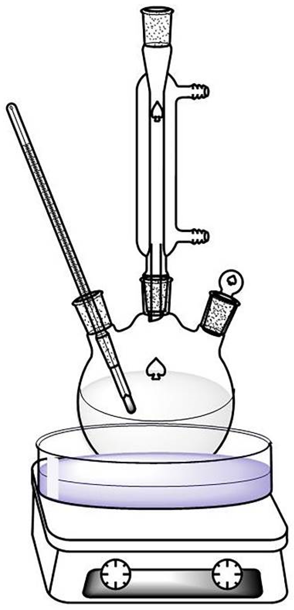
Figure 1. Batch reactor system.
Processes 12 01138 g001
Figure 2. Experimental design of ultrasound treatment for Ru/C catalyst.
Processes 12 01138 g002
Figure 3. Different types of free radical sites on carbon-based supports.
Processes 12 01138 g003
Figure 4. Free radical concentration on four catalysts before and after ultrasound treatment.
Processes 12 01138 g004
Figure 5. Distribution of Ru ions on four catalysts—SEM mapping image.
Processes 12 01138 g005
Figure 6. The concentration change curve of Ru in the solution upon completion of the reaction.
Processes 12 01138 g006
Figure 7. Transmission electron microscope (TEM) image (a) and particle size distribution of catalyst SM4 (b).
Processes 12 01138 g007
Figure 8. Distribution of Ru ions on catalysts after ultrasound treatment—TEM scan.
Processes 12 01138 g008
Figure 9. Adsorption–desorption curves (a) and pore size distribution (b) of four catalysts.
Processes 12 01138 g009
Table 1. Sample description.
NumberSample Description
SM05% Ru/C catalyst-1, a particle size range of 4–8 mesh
SM15% Ru/C catalyst for 100 reactions, a particle size range of 4–8 mesh
SM25% Ru/C catalyst for 150 reactions, a particle size range of 4–8 mesh
SM45% Ru/C-2 catalyst, a particle size range of 10–20 mesh
Table 2. Specific surface area, average pore diameter, and pore volume of four catalysts.
Catalyst SamplesSpecific Surface Area (m2/g)Average Pore Diameter (nm)Pore Volume (cm3/g)
SM01407.41.20.5
SM11058.31.20.4
SM2939.31.20.4
SM41165.81.20.5
Disclaimer/Publisher’s Note: The statements, opinions and data contained in all publications are solely those of the individual author(s) and contributor(s) and not of MDPI and/or the editor(s). MDPI and/or the editor(s) disclaim responsibility for any injury to people or property resulting from any ideas, methods, instructions or products referred to in the content.