Abstract
The classifier is an essential tool for the development of contemporary engineering technology. The application of classifiers is to categorize mixed-sized particles into multi-stage uniform particle sizes. In current studies, the particles in the classifier obtain their initial velocity when feeding. The classification effect is impacted by the inability to precisely control the initial state of the particles. To solve this problem, a pusher feed classifier was designed in this study, and a numerical simulation was performed to investigate its flow field characteristics and classification performance using the RNG-DPM method. A pusher is utilized to achieve particle feeding without initial velocity and to precisely control the initial state of the particles in the classification flow field. A newly developed two-way air inlet structure is designed to provide a superimposed flow field and enable the five-stage classification. Our results show that this pusher feed classifier has the best classification effect when the vertical airflow velocity is 10 m/s and the horizontal airflow velocity is 3 m/s. Meanwhile, the classification size ratio (CSR) from outlet 1 to outlet 5 was 1.24, 0.55, 0.45, 0.39, and 0.15, respectively.
1. Introduction
In powder technology, particle size is one of the main factors determining the performance of powder products and their application efficiency. Particle classification is an important method to obtain powders of different particle sizes. Common types of classifiers include centrifugal classifiers [1], gravity classifiers [2], inertial classifiers [3], and fluidized bed classifiers [4], which are designed based on the forces in the fluid resulting from particles with various particle sizes.
With the development of powder technology, the production of powder particles with fine and uniform sizes has become a topic of great interest. Thus, a matched powder particle classifier is indispensable for current development. Many researchers have investigated the structural innovation and parameter optimization of different types of classifiers. In the centrifugal classifier and fluidized bed classifier, the particles are mainly fed by airflow conveying, and the centrifugal force is used to classify the particles. Examples include vortex classifiers [5,6,7,8], cyclone classifiers [9,10,11], and fluidized bed turbine classifiers [12,13]. These classifiers have the characteristics of high classification efficiency, and are applicable to the classification of fine particles. However, only two levels of powder particles can be classified with these classifiers. In gravity-inertia-type classifiers, gravity and inertia forces are mainly relied on to classify particles. The horizontal basin and the inverse gravity basin can be constructed at the same time. Therefore, different particle sizes are subjected to different gravity and inertia forces, resulting in different trajectories and the realization of a multi-stage classifier of particles [14,15]. Particles mainly rely on their gravity or the airflow to complete the feeding. The particles carry the initial velocity into the classified flow field, and it is difficult to accurately control the initial kinetic energy of particles of different sizes, which affects the final classification accuracy and classification efficiency [16,17].
The initial state of particles before entering the classified flow field can be accurately controlled by changing the particle feeding method. Dang et al. [18] designed a cyclone classifier with a “step positioning” inlet channel so that the particles are fed from four inlets. Li et al. [19] installed a dispersing structure at the particle inlet of a gravity classifier to feed the particles uniformly. Banjac et al. [20] designed a “Z” type particle inlet so that the particles enter the classified flow field along a “Z” type slope. Weingerl et al. [21] designed a conveyor belt feeding structure to complete the particle feeding. Changing the feeding method of the classifier allows the particles to maintain a stable feeding speed and uniform feeding concentration, which can reduce the mutual collision and agglomeration phenomenon between particles. Compared with the centrifugal classifier, the gravity inertia classifier can perform a variety of structural innovations and optimization designs. It is necessary to make particles have accurate control and acquisition of kinetic energy before entering the classified flow field. Improving the control of the initial state of the particles has brought new challenges to the design of traditional classifiers.
In recent years, computational fluid dynamics (CFD) has been widely used in the design and optimization studies of classifiers [22,23]. In simulating particle motion, discrete phase model (DPM) and discrete element method (DEM) are commonly used. DPM has a larger time step and less stored information than DEM and is more suitable for simulating thin-phase flows with a volume fraction of less than 10% [24]. Zhang et al. [25] used DPM to simulate the motion of coke particles in the flow field and optimized the design of a new downward-exit cyclone classifier. Guo et al. [26] used the DPM to track the particle trajectories and optimize the design of the classifier. Some turbulence models were used to simulate the flow inside the classifier. The two-equation models, such as the standard - model and the renormalization group (RNG) - model [27], the Reynolds stress model (RSM) [28], and the large eddy simulation (LES) [29]. Among them, RSM and LES have higher accuracy for the prediction of complex flows but require more computational time. When researching and designing a new type of classifier, the main observation is the trajectory of the particles; the - model can be preferred. Compared with the standard - model, the RNG - model adds a computational formula to the turbulent viscous term. Because of the consideration of the impacts from eddy currents, the RNG - model improves computational accuracy; therefore, it is more applicable in near-wall turbulence [30,31]. In the design study of a new type of classifier, CFD simulation technology can be utilized to save design time and provide more convenient methods and approaches.
In this study, a pusher feed classifier was designed. A pusher feed structure was designed to achieve particle feeding without initial velocity. So that particles of different sizes have the same initial state before entering the classified flow field. At the same time, the horizontal airflow and vertical airflow bidirectional intake structures were designed to form a superposition classified flow field to realize the multi-stage classification of particles. The classification effect and classification performance of the pusher classifier were simulated using the RNG-DPM method to explore the optimal structural and process parameters of the classifier. The accuracy of the simulation results was also verified by experimental studies.
2. Materials and Methods
2.1. Design of Pusher Feed Classifier
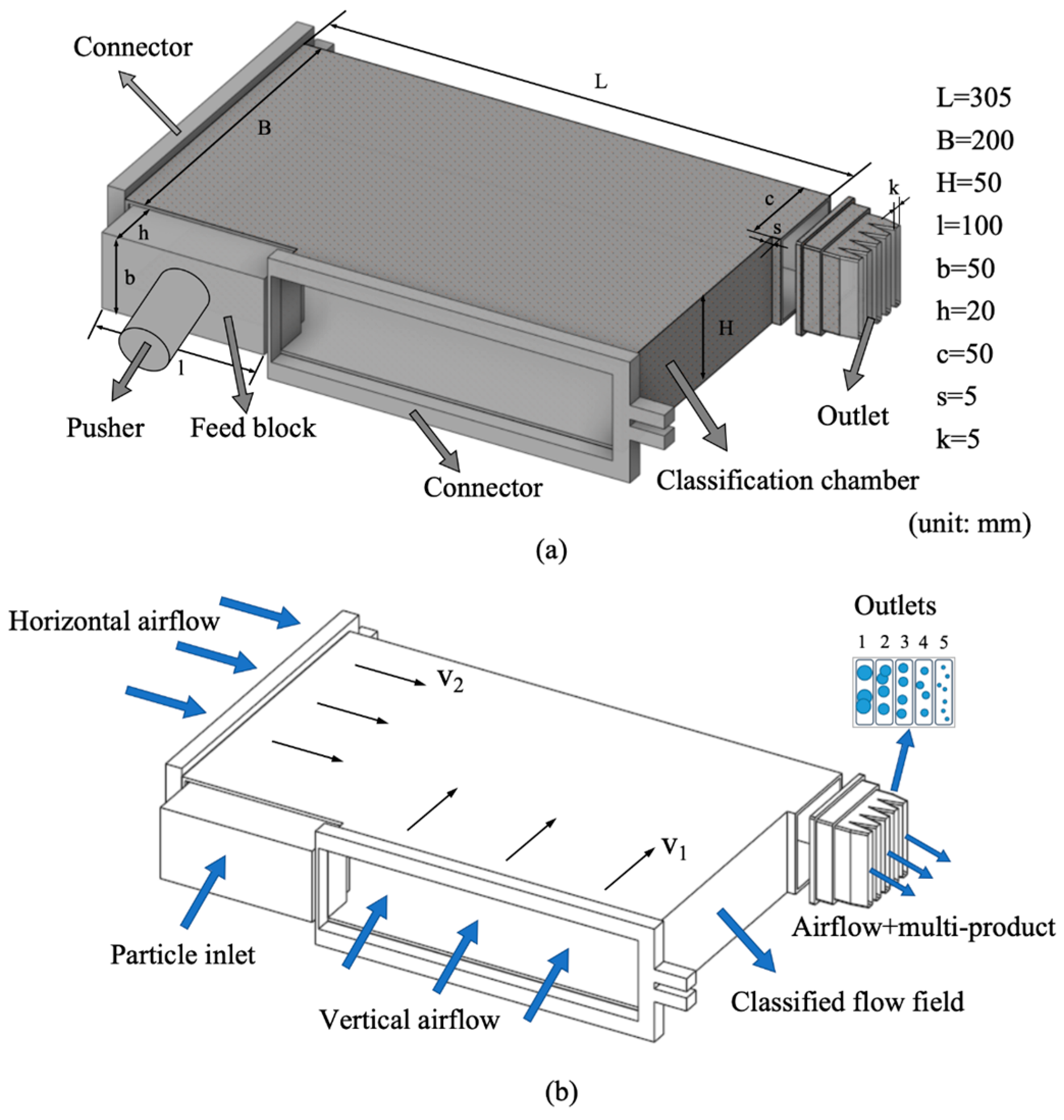
The structural size and working process of the pusher feed classifier are shown in Figure 1. The classifier mainly consists of a pusher, feed block, connector, classification chamber, and outlet. The basic size of the classification chamber is 200 mm × 300 mm × 50 mm, the width of the feed block is 100 mm, and the pusher pushes the feed block to move up and down to complete the feeding of particles. The left side and the lower side of the classifier are connected to the blower through the connector and are fed with horizontal airflow (V2) and vertical airflow (V1), respectively. The outlet of the classifier is set above the right side, and the outlet cross-section is 50 mm × 50 mm square, which is equidistantly divided into five outlets through the partition board and is numbered 1–5 from the top to the bottom in order.
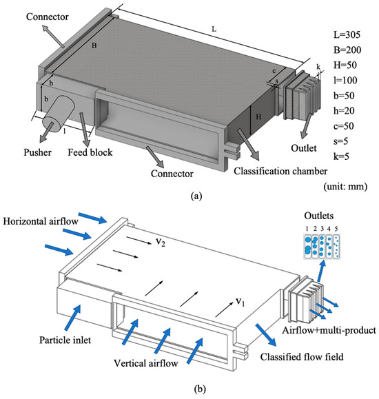
Figure 1.
(a) Pusher feed classifier structure size. (b) Particle classification working process.
The particles of this pusher feed classifier are kept uniformly fed without initial velocity under the movement of the pusher. The particles always remain relatively stationary on the surface of the feed block during the feeding process, and the initial velocity of the particles is 0. The particles of different particle sizes have the same kinetic energy before entering the classified flow field. The left side and the lower side of the classification chamber are fed with horizontal airflow V2 and vertical airflow V1, and the two-way airflow is arranged at 90°, which is superimposed to form a stable classified flow field. The horizontal airflow V2 brings the stationary particles into the classified flow field, and the particles of different sizes are subjected to different gravity, buoyancy, and fluid traction, obtaining different kinetic energy and producing different trajectories. The particles of different sizes are subjected to different gravity, buoyancy, and fluid traction, obtaining different kinetic energies and producing different trajectories.
2.2. Mathematical Model
2.2.1. Geometric Modeling and Meshing
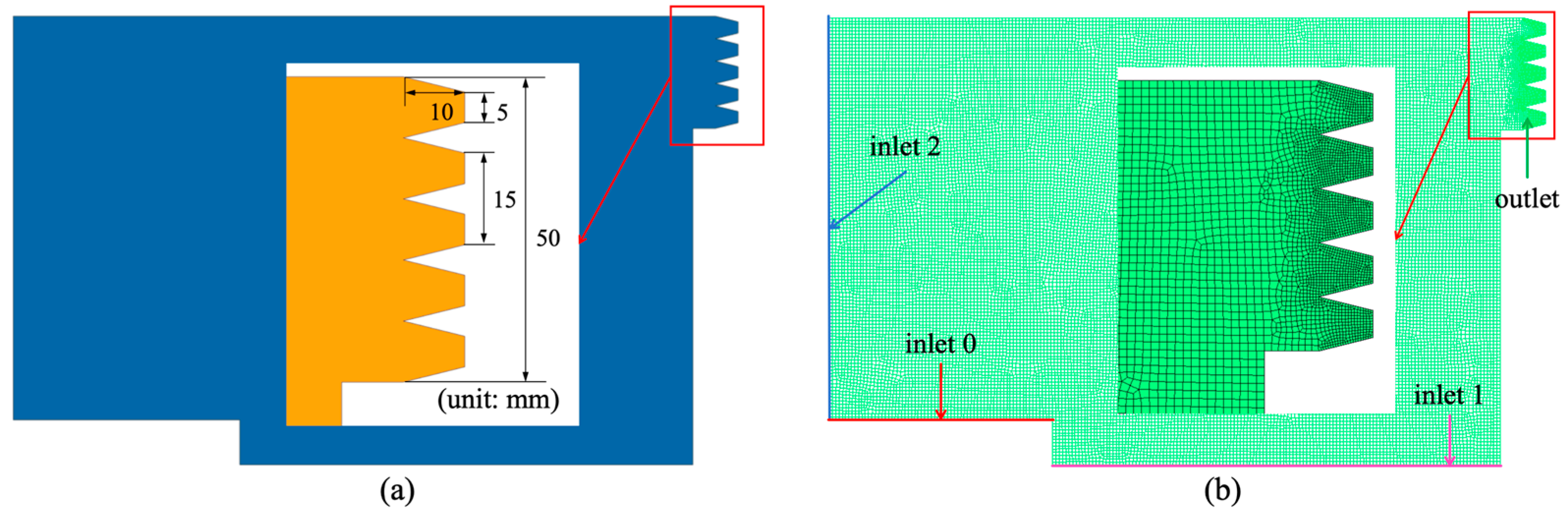
Establish the XoY coordinate system by taking the intersection point between the left wall of the classifier and the feed inlet of the pusher as the coordinate origin, the horizontal airflow direction as the positive direction of the X-axis, and the gravity direction as the negative direction of the Y-axis. A geometric structure was constructed for the classifier basin inside the classification chamber, as shown in Figure 2a.
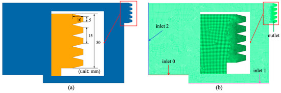
Figure 2.
(a) Geometric structure. (b) The mesh division.
In this study, ICEM 2021 software is utilized to mesh the computational domain model of the pusher feed classifier. Before meshing, the computational domain model needs to be divided into parts, as shown in Figure 2b. The particle inlet is set as “inlet 0”, the vertical airflow inlet is set as “inlet 1”, the horizontal airflow inlet is set as “inlet 2”, the particle and airflow The outlet of the particles and airflow is set as “outlet”, and the other surfaces are set as “walls”. Use a tetrahedral mesh shape for unstructured meshing. The maximum allowed mesh size is set to 0.1 mm globally, and the maximum allowed mesh size is set to 0.05 mm for the “outlet” region. The total number of meshes is 270,981.
To ensure computational accuracy and reduce the simulation time, four mesh schemes are adopted to verify mesh independence. The pressure drops at the inlet and outlet of the pusher feed classifier with different mesh numbers are shown in Table 1. The pressure drops at the inlet and outlet of the pusher feed classifier with different mesh numbers are shown in Table 1. The number of gratings was 157,725, 270,981, 308,235, and 417,399. The rate of change of pressure drop at the inlet and outlet of the classifier was 8.4%, 0.3%, and 0.08%, respectively, with an increase in the number of gratings. When the mesh number reaches 270,981, the variation rate of the pressure drop between the inlet and outlet is less than 1%, and the influence of the mesh number on the pressure drop between the inlet and outlet is negligible, so the mesh model with the number of 270,981 is used for the subsequent simulation. As shown in Table 2, these are the quality detection results for the number of grids under 270,981. The detection results of its mesh quality are within the range of the index, and the mesh has a good quality [32].

Table 1.
Mesh independence verification.
Table 2.
Grid quality test results [32].
2.2.2. RNG - Turbulence Model
In this study, the classifying airflow is air, which is chosen for its low velocity and is assumed to be incompressible and turbulent. The particle trajectories are of high interest in this study, and the - model can be prioritized. The RNG - model is a simulation and calculation method based on reformed groups. Its equations for turbulent kinetic energy and dissipation rate are as follows, respectively:
where: is the generation term of turbulent kinetic energy caused by the average velocity gradient; and are the model coefficients of turbulent kinetic energy and dissipation rate , respectively; and are empirical constants.
Simulation of the classifying airflow in a pusher feed classifier using the RNG - model allows the description of small-scale motions in the context of large-scale motions. Compared to the standard - model, the dissipation rate equation of the RNG - model incorporates an average strain rate in the calculation of the dissipation term, which takes into account the effect of eddies in turbulent phenomena and improves the accuracy of the calculation in the case of strained and rotating flows. Meanwhile, the constant term in the RNG - model is derived accurately, which is more advantageous for the calculation of turbulence near the wall, and has better adaptability and accuracy in simulating the classification process of this pusher feed classifier [31].
2.2.3. Particle Phase Model
In this study, the volume fraction of the particles is much less than 10%, so the DPM model is used to track the particle trajectories. Particles in a fluid are mainly subjected to gravity , fluid trailing force , flotation force , and other forces (Magnus force, Bassett force, etc.). In this study, the classified particles are considered spheres and the dynamic equilibrium equations of the particles in the classifier based on Newton’s second law are as follows:
where and represent the density of particles and fluids, whereas and represent the velocity of particles and fluids, is the diameter of the particle, is the acceleration of gravity, is other interaction forces, and is the particle resistance coefficient.
In this study, the flow field characteristics and classification performance of a pusher feed classifier are simulated by the RNG - model to simulate the classified flow field and the DPM model to track the particle trajectories. The feasibility of this combined model has been verified in Raeesh’s study on sedimentation tanks [33].
2.3. Simulation Boundary Conditions and Parameter Settings
The numerical simulation is conducted using ANSYS 2021 Fluent software. As shown in Figure 3, the boundary conditions are set as three “velocity inlets” and one “pressure outlet”, and the rest are “walls”. The particle injection type is “surface”, the surface shear condition was set as “no-slip”, and the velocity is 0 (Velocity-inlet 0 = 0). the lower boundary is set as “Velocity-inlet 1”, and the left boundary is set as “Velocity-inlet 2”. The vertical and horizontal airflow velocities are denoted by V1 and V2, respectively, and their values are equal to the inlet value of each velocity. Five “Pressure outlets” are provided on the right side. The particles are categorized into two states in this study. For studying the particle trajectories, single particle size particles were used, as shown in state 1 in Figure 3. The diameter distribution was set as an “Unrosin” distribution, the number of particles was 10, and the number of streams was 2. A total of 20 particles were generated randomly from the inlet surface. For studying the flow field state and classification effect, mixed multi-particle size particles were used, as shown in state 2 in Figure 3. The diameter distribution was set as a “Rosin–Rammler” distribution; the number of particles was 150, and the number of streams was 200. A total of 30,000 particles were generated randomly from the inlet surface. The minimum particle size is 10 μm, the maximum particle size is 50 μm, and the average particle size is 30 μm. The mean value of the solved diffusion coefficients obtained from the “Rosin–Rammler” distribution formula for each of its particle sizes at the cumulative mass fraction share, the spread parameter, is 1.46.
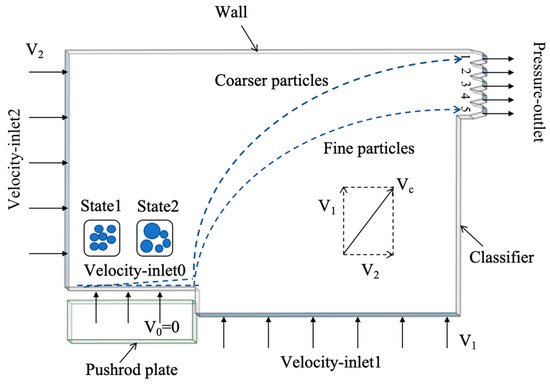
Figure 3.
The classification parameter and boundary conditions.
In this case, air was used for the fluid, and seafoam mineral powder was used for the particle material. The specific physical and chemical parameters are shown in Table 3.
Table 3.
Simulation parameters.
2.4. Classification Experiment
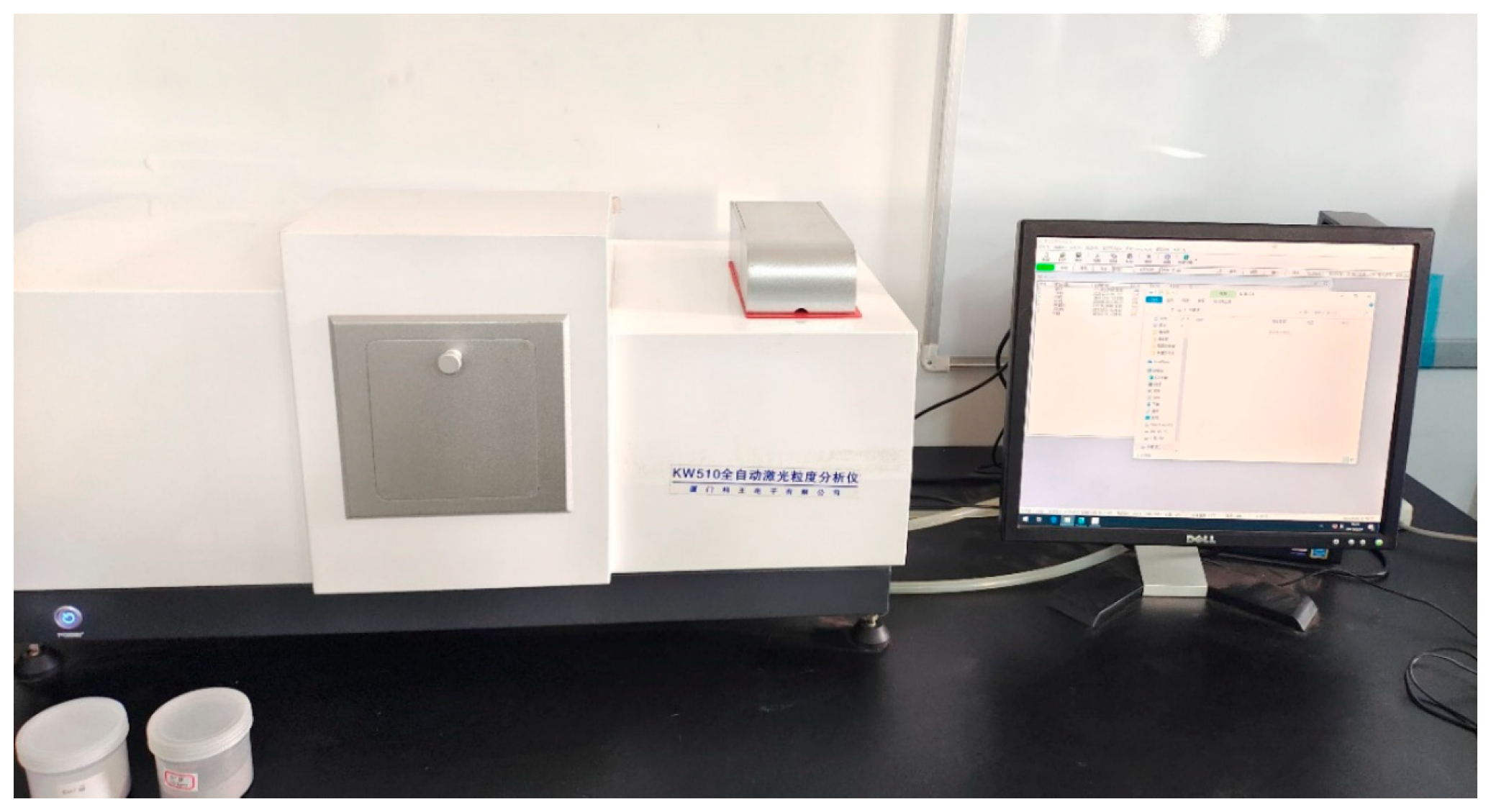
The particle material used in this experiment was seafoam particles, produced in Xiangtan, Hunan, China, and the same batch of seafoam particles was used in all the classification experiments. As shown in Figure 4, the seafoam samples were purchased for this experiment. Firstly, the particle size distribution of the particles was measured by the KW510 Automatic Laser Particle Sizing Analyzer, as shown in Figure 5. The particle size range of the seafoam particles used in this experiment was 0.5–65 μm, and the median particle size value of the particles, d50, was about 15 μm.
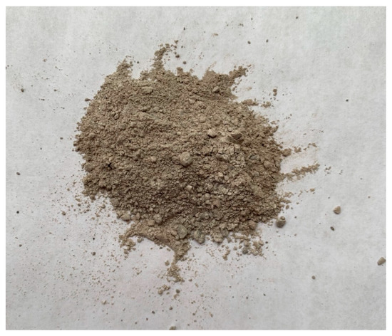
Figure 4.
Seafoam particles and raw materials.
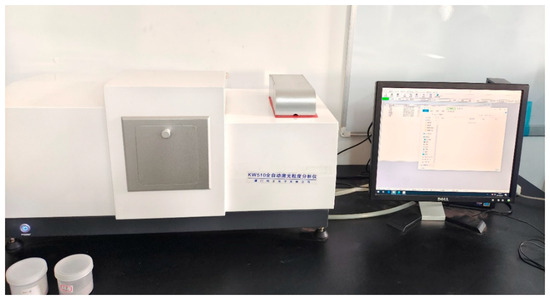
Figure 5.
KW510 Automatic Laser Particle Sizing Analyzer.
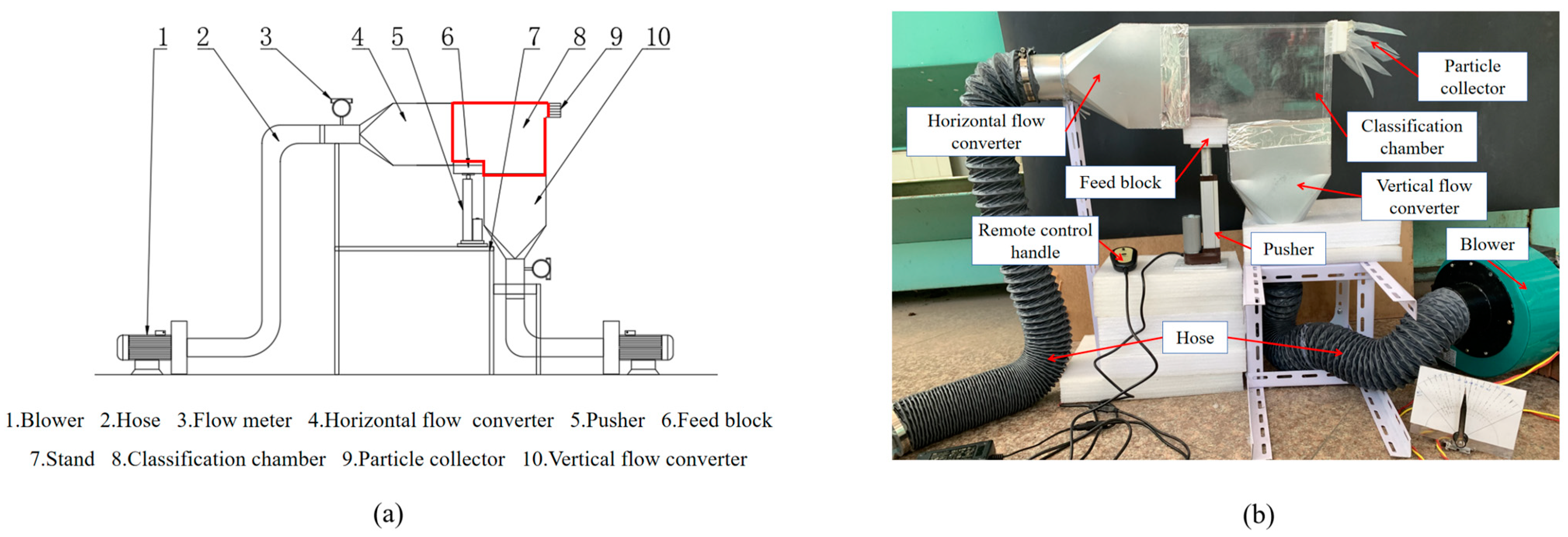
The experimental setup mainly consists of a classification chamber, pusher, feed block, converter, blower, hose, and stand. As shown in Figure 6, the pusher is a flat-topped pusher with a stroke of 100 mm, a speed of 5 mm/s and a torque of 700 N. A feed block is mounted on its top plane. The material used for the classification chamber is polymethylmethacrylate (PMMA), which is constructed by adhesive splicing. The outlet of the classifier was made by 3D printing, the material was photosensitive resin, and the size of the outlet was 50 mm × 50 mm, which was divided into five same-sized outlets equally from top to bottom using a 1 mm thin block, numbered 1–5 in order.
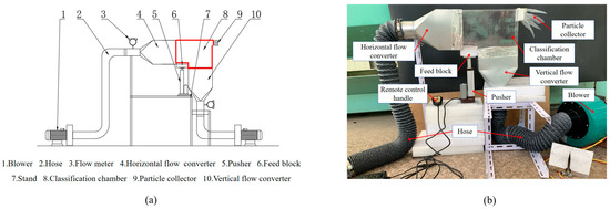
Figure 6.
(a) Schematic diagram of the experimental setup. (b) Physical diagram of the experimental setup.
Before the beginning of the experiment, the raw material of seafoam particles was placed statically on the feed block, and the handle was used to control the up-and-down movement of the pusher to feed the particles into the classification chamber. Start the blower to generate airflow through the conversion connector into the classification chamber to form a stable airflow field to classify the particles. Set different feed depths by adjusting the stroke of the pusher and the flow meter of the blower to control the size of the grading airflow. After classification, the particles are collected at different outlets, and the particle size distribution is measured by the KW510 Automatic Laser Particle Size Analyzer.
3. Results and Discussion
3.1. Characterization of the Classified Flow Field
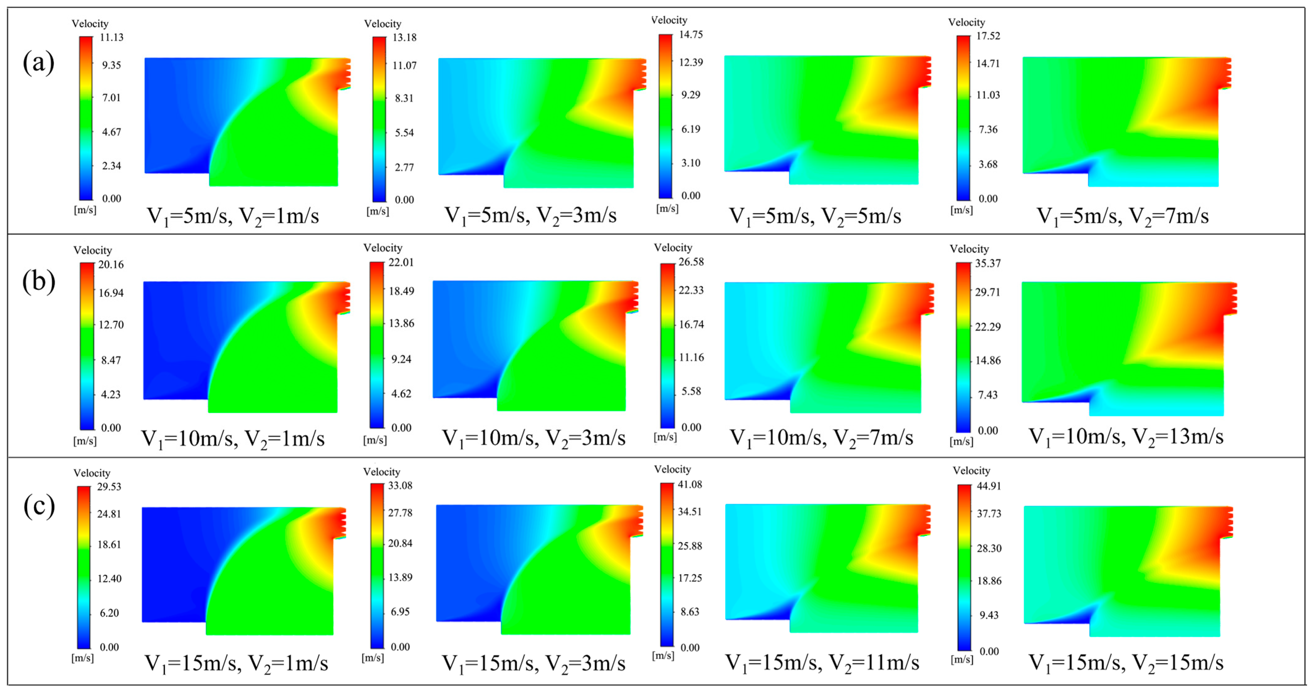
The classified flow field was simulated and studied under different classification parameters. The velocity distribution diagrams of the flow field in the pusher feed classifier under different sizes of vertical airflow V1 and horizontal airflow V2 are shown in Figure 7.
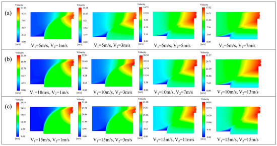
Figure 7.
Flow field character at different classification parameters. (a) V1 = 5 m/s, velocity distribution at different V2, (b) V1 = 10 m/s, velocity distribution at different V2, (c) V1 = 15 m/s, velocity distribution at different V2.
When V2 is much smaller than V1, a large static region appears at the intersection of the horizontal airflow inlet and the particle inlet. Due to the interference between the vertical airflow and the horizontal airflow, the vertical airflow will hinder the normal flow of the horizontal airflow. At this time, the horizontal airflow velocity is too small, which will affect the particle feed. As V2 increases, the static region decreases, and the degree of particle feeding increases. When V2 increases to 1/3–1/5 of V1, the particles have a longer residence time and classification process in the classified flow field and can be fully classified. The classifier has a stable classification flow field and optimal classification.
When V2 is equal to or greater than V1, the static region in the classified flow field disappears, and the classified flow field remains unchanged. The residence time of the particles in the classified flow field is shortened, and the particles are incompletely classified. At the same time, the fine particles are easy to follow in the horizontal airflow, resulting in the phenomenon of particle mixing and entrainment.
3.2. The Effect of Particle Classification under Different Velocity Matching
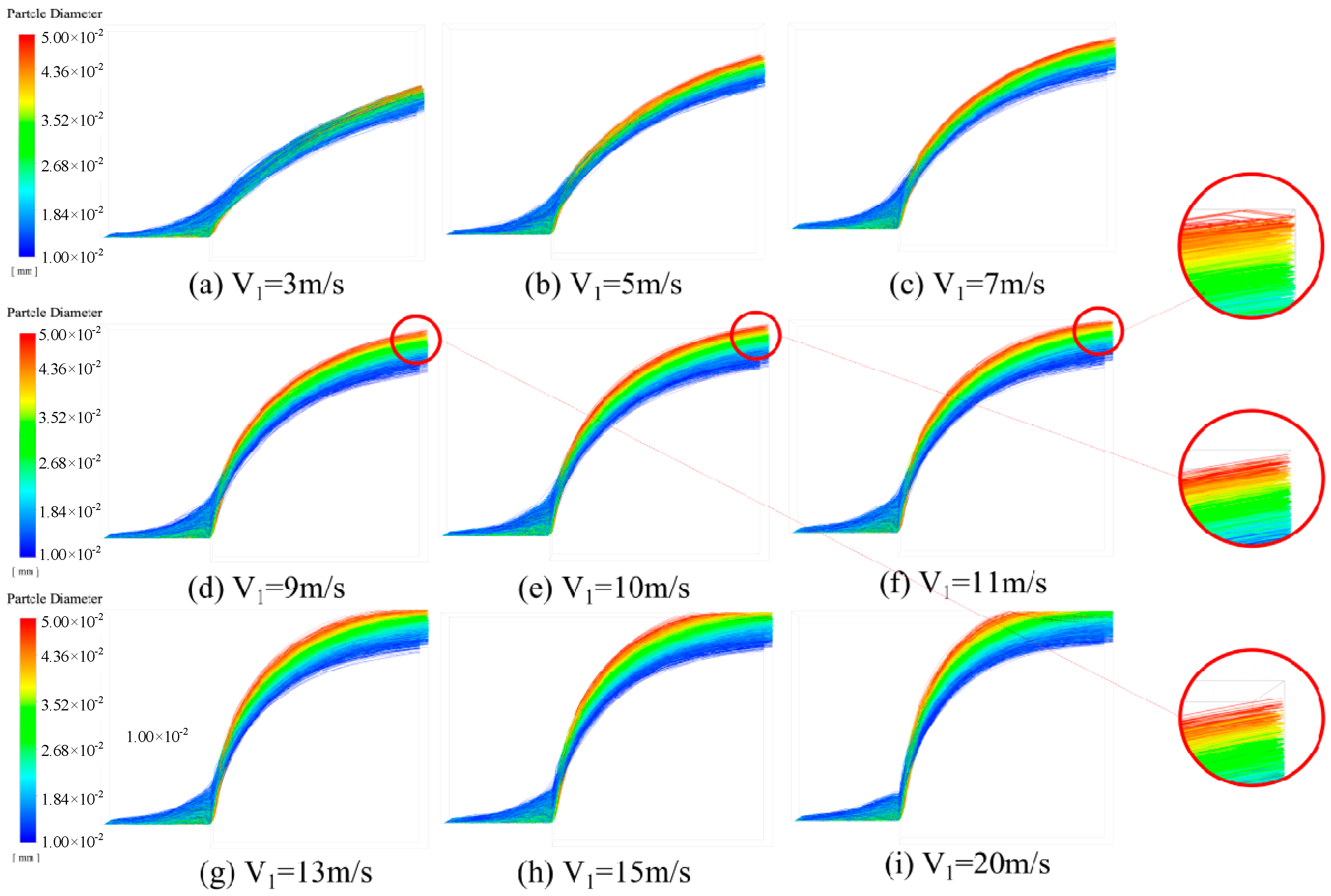
The particles are affected by the horizontal airflow V2 and the vertical airflow V1 in the classifier. Under different velocity matching schemes, different classification effects are produced. Through the above analysis of the classified flow field, the classification effect of the pusher feed classifier is simulated by keeping V2 = 3 m/s constant and changing V1. The particle classification effect under different velocity matchings is shown in Figure 8.

Figure 8.
Particle classification effects under different velocity matching schemes.
When V1 is less than 10 m/s, the mixed particles are not completely separated and cannot completely flow out of the outlet. The dispersion of the separated particles is low, and the classification effect is poor. When V1 is greater than 10 m/s, the mixed particles can be fully separated. However, the coarse particles will hit the wall and impact the classification effect. When V1 = 10 m/s, the mixed particles can be fully separated and concentrated at the outlet of the classifier. Therefore, when V2 = 3 m/s and V1 = 10 m/s, the pusher feed classifier has the best classification effect.
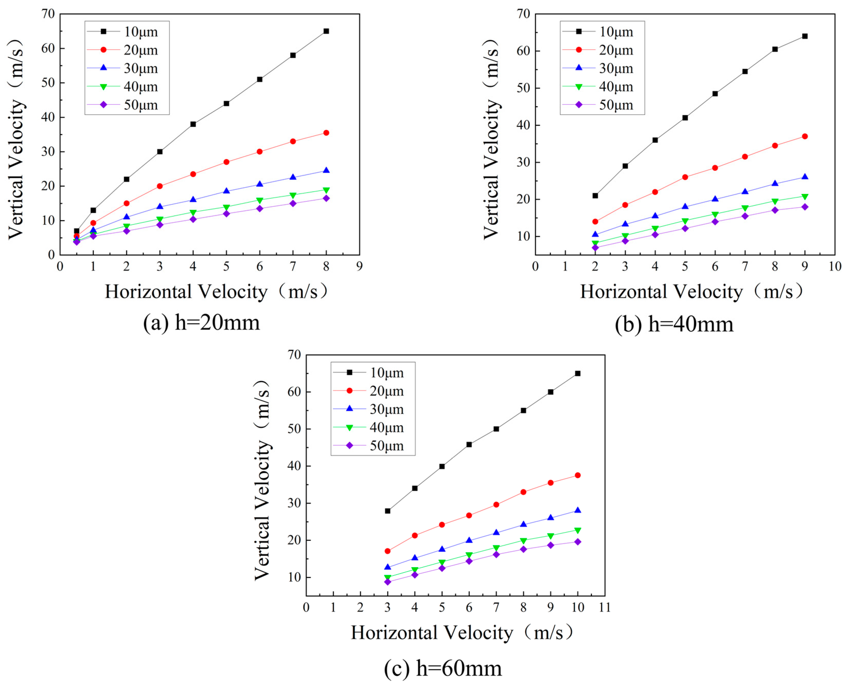
To further investigate the effect of different feed depths on the classification effect. The feed depths h = 20 mm, 40 mm, and 60 mm were selected for simulation. The maximum particle sizes were set to be 10 μm, 20 μm, 30 μm, 40 μm, and 50 μm, making the largest particles flow out of the No. 1 outlet of the classifier. The relationship between horizontal airflow velocity V2 and vertical airflow velocity V1 was obtained, as shown in Figure 9.
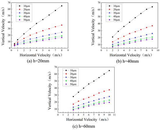
Figure 9.
Velocity matching scheme for different feed depths (h).
Under three different feed depths, the horizontal airflow velocity V2 and the vertical airflow velocity V1 in the classifier are in an approximately linear relationship. The slop is inversely related to the particle size, and different feed depths give different slopes. When the horizontal air velocity remains constant, the particle size decreases and the required vertical air velocity increases. Therefore, the classification energy consumption of fine particles is greater than that of coarse particles. Meanwhile, with the increase in feed depth, the vertical airflow gradually decreases, and the energy consumption of classification decreases. However, when the particle size is larger than 30 μm, the feed depth no longer affects the classification effect.
3.3. Trajectories of Particles of Different Sizes
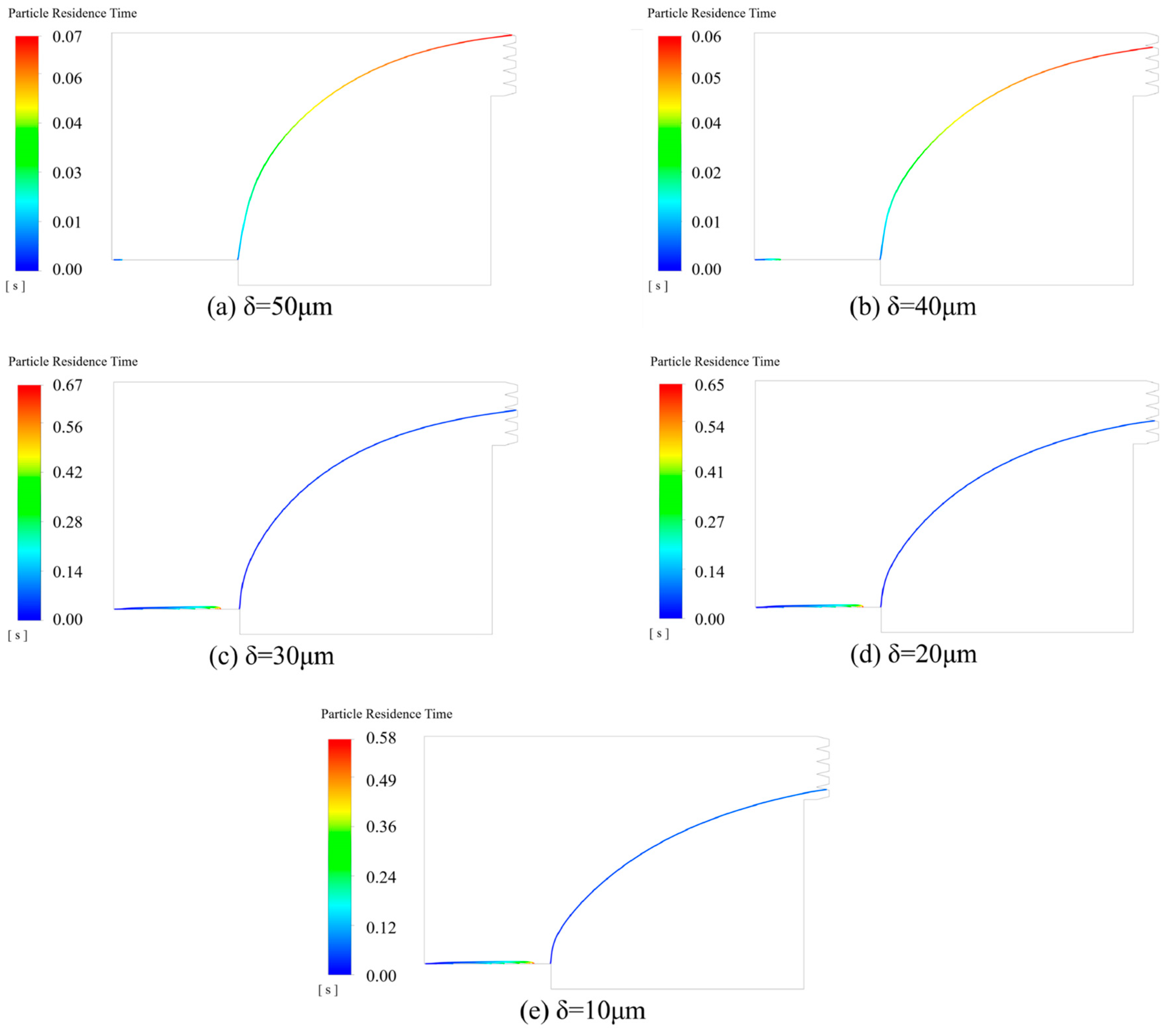
Different particle sizes have different trajectories. To investigate the trajectories of different particle sizes in the pusher feed classifier, the feed depth was set to h = 20 mm, V1 = 3 m/s, V2 = 10 m/s, and the pressure at the outlet was 1.01 × 10⁵ Pa (the relative pressure was 0). The simulations were performed for particle sizes of 10 μm, 20 μm, 30 μm, 40 μm, and 50 μm using a single particle size in state 1. The traced particle trajectories are shown in Figure 10.
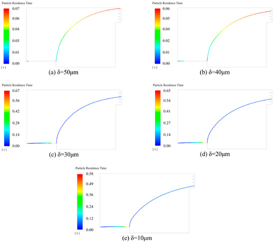
Figure 10.
Trajectories of particles at different particle sizes .
The trajectory of particles in a classified flow field is mainly influenced by the Stokes number. The Stokes number is used to characterize the ratio of particle inertial action to turbulent diffusion action. It is related to the diameters of the particles [34], can be defined as the ratio of the particle relaxation time to the system response time, and is calculated as follows:
where is the Cunningham coefficient, is the average flow rate of fluid, is the characteristic length, and is the particle diameter.
As seen in Figure 10a, particles with a size of 50 μm flow out of outlet No. 1 at the topmost part of the classifier. There are almost no particles left on the inlet surface. Due to the large particle size, the Stokes number is large and is affected by the inertia force. The particles in the classified flow field are mainly influenced by the vertical airflow and are fully classified to the topmost outlet. As the particle size decreases, the Stokes number decreases, and the particles affected by the turbulent diffusion effect become larger. The control ability of the horizontal airflow on the particles increases, and the particles tend to follow the original streamlined trajectory. As shown in Figure 10e, particles with a size of 10 μm flow out of outlet No. 5 at the bottom of the classifier. When = 50 μm, particles flow out of outlet 1. When = 40 μm, the particles flow out of outlet 2. When = 30 μm, particles flow out of outlet 3. When = 20 μm, the particles flow out of outlet 4. When = 10 μm, the particles flow out of outlet 5. The pusher feed classifier can classify particles with a size of 10–50 μm in five stages.
3.4. Outlet Particle Size Distribution
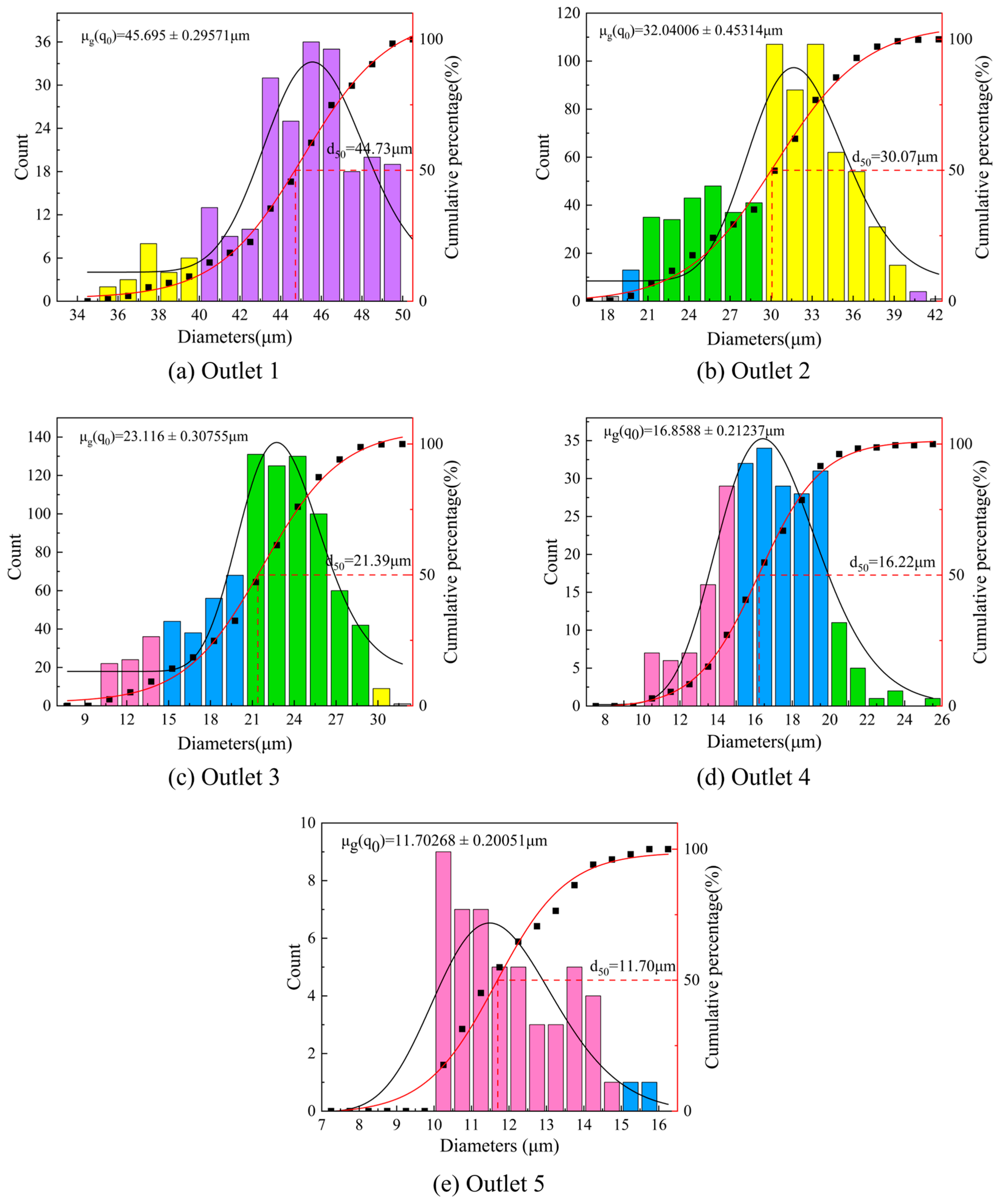
To investigate the particle size distribution law at each outlet of the pusher feed classifier, set the feed depth h = 20 mm, V1 = 10 m/s, V2 = 3 m/s, and simulate the mixed particles with a particle size of 10–50 μm. The histogram of particle size distribution and cumulative frequency distribution at each outlet were obtained, as shown in Figure 11. The Gaussian function and Boltzmann function were used to fit them, and the corresponding fitting curves were obtained, respectively. In the figure, μg(q0) is the geometric mean of particle size, and d50 is the median particle size of the particles. Different colors represent particles of different size ranges.

Figure 11.
Particle size distribution diagram under each outlet.
It can be seen that both μg (q0) and d50 decrease gradually from outlet 1 to outlet 5. The particles above 30 μm mainly flow out of outlet 1 and outlet 2, and the particles below 30 μm mainly flow out of outlet 3, outlet 4, and outlet 5. There are overlapping parts between the same colors, and there is particle size overlap between two adjacent outlets. There are overlapping parts between the same colors, and there is particle size overlap between two adjacent outlets. The overlap is more serious for particles below 30 μm. Because the fine particle size is small, it is easy to move with the horizontal airflow. The separation is incomplete, and the particles are mixed. As the particle size increases, the coarse particles are fully separated, reducing the inter-particle mixing phenomenon. The coarse particles in the pusher feed classifier have a better classification effect. However, from the range of particle size distribution at each outlet, the width of fine particle size distribution at outlet 5 is narrower than other outlets. And with the increase in μg (q0), the width of particle size distribution is becoming larger and larger. This indicates that the fine particles obtained by classification have a more concentrated distribution and better monodispersity.
3.5. Experimental Results Analysis
According to the simulation results, particle classification experiments were carried out. Seafoam mineral powder was used as the particle raw material, and its particle size distribution range was roughly 0.5–65 μm, and the median particle size value d50 of the particles was about 15 μm. Scheme 1, Scheme 2, and Scheme 3 were set up, respectively, and the horizontal air velocity V2 was 1 m/s, 3 m/s and 11 m/s, and the vertical air velocity V1 was 5 m/s, 10 m/s, and 15 m/s. The three schemes corresponded to the three simulation conditions in Figure 7. The classification effect is evaluated using the classification size ratio (CSR). The larger the value of CSR, the higher the degree of coarse and fine particle classification and the better the classification effect [2,35]. It can be defined as:
where is the particle diameter corresponding to 10% of the accumulated volume of particles and is the particle diameter corresponding to 90% of the accumulated volume of particles.
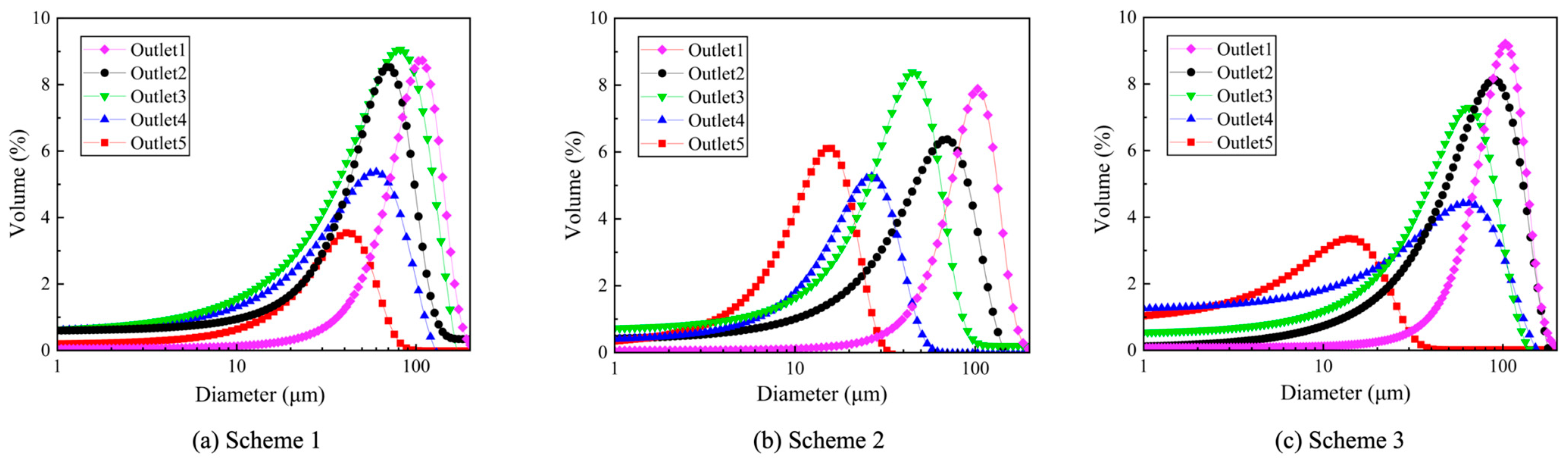
The particle size distribution of each outlet obtained under Scheme 1, Scheme 2, and Scheme 3 is shown in Figure 12. As seen from Figure 12b, the seafoam particles obtained from the classification have different particle sizes at each outlet, and the pusher feed classifier can carry out multi-stage classification of seafoam particles with mixed particle sizes. The particle size of the seafoam particles at each outlet may overlap, and the particle size at each outlet has the best distribution effect under Scheme 2, and particles of different sizes can flow out from different outlets.
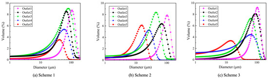
Figure 12.
Particle size distribution under different schemes.
Comparing Scheme 1 and Scheme 2, when the horizontal airflow velocity V2 = 1 m/s, the overlap range of particle size between the outlets is larger, as shown in Figure 12a. Since the horizontal airflow velocity and the vertical airflow velocity are both smaller at this time, the degree of feeding of particles is reduced, fine particles are easily left in the plane of the classification outlet, and the particles are easily classified incompletely. Comparing Scheme 3 with Scheme 2, when the horizontal airflow velocity increases from 3 m/s to 7 m/s, the particles have a better feeding degree, and more dispersed fine particles can be obtained, as shown in Figure 12c. Where the coarse particles have a higher degree of particle size overlap than the fine particles. Due to the vertical air velocity V1 = 15 m/s at this time, the particles are less affected by the vertical airflow in the classification process, and the particles are easier to flow with the horizontal airflow. Resulting in coarse particles that are easy to classify as incomplete, resulting in the entrainment phenomenon. The energy consumption of the classification at this time is greater than that of Scheme 2.
The CSR values at different outlets in Scheme 2 are shown in Table 4. The value obtained at outlet 1 is 131.2 μm, and the CSR value is 1.24. The best classification effect is obtained for coarse particles from outlet 1. From outlets 1–5, its , and CSR values are gradually decreasing. The CSR values of each outlet particle distribution obtained at V1 = 10 m/s and V2 = 3 m/s under the parameters of Section 3.1 are shown in Table 5. The comparison shows that the simulation results have the same trend as the experimental results. It indicates that the coarse powder particle product obtained from the classification of this pusher feed classifier has a higher degree of classification and a better classification effect than the fine powder particle product.
Table 4.
Particle size distribution at different outlets in Scheme 2.
Table 5.
Values of particle distribution at each outlet obtained from simulation results at V1 = 10 m/s and V2 = 3 m/s.
4. Conclusions
In the current particle classification technology, it is very important to precisely control the kinetic energy of particles of different sizes before they enter the classified flow field. In this study, a pusher feed classifier was designed. Utilizing a pusher to realize no initial velocity feeding of particles, particles of different sizes have the same kinetic energy before entering the classified flow field. At the same time, to build a horizontal airflow and vertical airflow bidirectional intake structure, the formation of a superposition of classified flow fields is necessary, to achieve the multi-stage classification of particles. The design of this pusher feed classifier is of research value to control the initial state of particles in the classified flow field. The RNG-DPM method was used to simulate the pusher feed classifier and was experimentally validated. The following conclusions were obtained:
- The pusher feed classifier has a stable classified flow field and a better classification effect when V2 is 1/3–1/5 of V1. When V2 = 3 m/s and V1 = 10 m/s, it has the best classification effect. With the increase in feed depth, the energy consumption for fine particle classification decreases.
- The pusher feed classifier can classify particles with a particle size of 10–50 μm in five stages. The geometric mean of particle size μg(q0) decreases from outlet 1 to outlet 5. There is particle size overlap between neighboring outlets. Coarse particles have a better classification effect, and fine particles have a more concentrated distribution and better monodispersity.
- The CSR values of the pusher feed classifier from outlet 1 to outlet 5 are 1.24, 0.55, 0.45, 0.39, and 0.15. Under suitable structural and process parameters, the particles can flow from outlet 1 to outlet 5 of the pusher feed classifier, from large to small. Coarse particles at outlet 1 have a better classification effect.
Author Contributions
Conceptualization, Y.Z. and X.Z.; Methodology, X.Z. and Y.L.; Formal analysis, X.Z. and C.W.; Investigation, X.Z.; Writing—original draft, X.Z.; Writing—review and editing, Y.Z., X.Z. and Z.M.; Supervision, Y.Z. and Z.M. All authors have read and agreed to the published version of the manuscript.
Funding
This research was supported by the National Natural Science Foundation of China (No. 52175254). The authors also acknowledge the Postgraduate Scientific Research Innovation Project of Hunan Province, China (CX20220603, CX20230550) for their support of this work.
Data Availability Statement
The datasets generated and analyzed during the present study are available from the corresponding author upon reasonable request.
Conflicts of Interest
The authors declare no conflicts of interest.
References
- Sun, Z.P.; Liu, C.Y.; Yang, G.; Chen, L. Orthogonal vortices characteristic performance evaluation and classification mechanism of a horizontal classifier with three rotor cages. Powder Technol. 2022, 404, 117438. [Google Scholar] [CrossRef]
- Zhou, Y.H.; Shen, W. Numerical simulation of particle classification in new multi-product classifier. Chem. Eng. Res. Des. 2022, 177, 484–492. [Google Scholar] [CrossRef]
- Blake, T.R. Assessment of fractional collection efficiency in louvered inertial particle classifiers. Powder Technol. 2017, 311, 432–438. [Google Scholar] [CrossRef]
- Jayarathna, C.K.; Moldestad, B.M.; Britt, M.E.; Tokheim, A. Improved multi-stage cross-flow fluidized bed classifier. Powder Technol. 2019, 342, 621–629. [Google Scholar] [CrossRef]
- Peng, J.; Hui, C.; Zhao, Z.; Fang, Y. Research and optimization of operating parameters of a rotor classifier for calcined petroleum coke. Processes 2024, 12, 603. [Google Scholar] [CrossRef]
- Abohelwa, M.; Benker, B.; Javadi, M.; Wollmann, A.; Weber, A.P. Limitation in the performance of fine powder separation in a turbo air classifier. Processes 2023, 11, 2817. [Google Scholar] [CrossRef]
- Sun, Z.P.; Liang, L.L.; Liu, C.Y.; Yang, G. Structural optimization of vortex finder for a centrifugal air classifier. Chem. Eng. Res. Des. 2021, 166, 220–226. [Google Scholar] [CrossRef]
- Fatahian, H.; Esmaeel, N.; Majid, E.; Ahmadi, G. Novel designs for square cyclone using rounded corner and double-inverted cones shapes. Powder Technol. 2021, 380, 67–79. [Google Scholar] [CrossRef]
- Li, Q.; Mou, X.; Fang, Y. Effects of a guide cone on the flow field and performance of a new dynamic air classifier. Processes 2022, 10, 874. [Google Scholar] [CrossRef]
- El-Emam, A.; Mahmoud, L.; Zhou, W.D.; Han, C. Performance evaluation of standard cyclone separators by using CFD-DEM simulation with realistic bio-particulate matter. Powder Technol. 2021, 385, 357–374. [Google Scholar] [CrossRef]
- Huang, L.; Yuan, J.L.; Pan, M.; Wu, J.D.; Qiao, J.P.; Jiang, H.S.; Duan, C.L. CFD simulation and parameter optimization of the internal flow field of a disturbed air cyclone centrifugal classifier. Sep. Purif. Technol. 2022, 307, 122760. [Google Scholar] [CrossRef]
- Jayarathna, C.K.; Moldestad, B.M.; Britt, M.E.; Tokheim, L.A. Impact of solids loading and mixture composition on the classification efficiency of a novel cross-flow fluidized bed classifier. Powder Technol. 2019, 336, 30–44. [Google Scholar] [CrossRef]
- Guo, M.; Le, D.K.; Sun, X.; Yoon, J.Y. Multi-objective optimization of a novel vortex finder for performance improvement of cyclone separator. Powder Technol. 2022, 410, 117856. [Google Scholar] [CrossRef]
- Petit, H.A.; Edgardo, F.I. The throat classifier: A novel air classifier for the control of dust in manufactured sands. Powder Technol. 2021, 390, 417–427. [Google Scholar] [CrossRef]
- Prasad, K.; Sachinraj, D.; Awasthi, A.; Mukherjee, A.K.; Ranjan, A. Intermediate size fine coal beneficiation by Reflux ™ Classifier using statistical approach. Powder Technol. 2020, 361, 548–561. [Google Scholar] [CrossRef]
- Wasilewski, M.; Brar, L.S. Effect of the inlet duct angle on the performance of cyclone separators. Sep. Purif. Technol. 2019, 213, 19–33. [Google Scholar] [CrossRef]
- Zhou, J.W.; Shangguan, L.J.; Gao, K.D.; Wang, Y.H.; Hao, Y.X. Numerical study of slug characteristics for coarse particle dense phase pneumatic conveying. Powder Technol. 2021, 392, 438–447. [Google Scholar] [CrossRef]
- Dang, K.L.; Joon, Y.Y. Numerical investigation on the performance and flow pattern of two novel innovative designs of four-inlet cyclone separator. Chem. Eng. Process. Process Intensif. 2022, 150, 107867. [Google Scholar] [CrossRef]
- Li, H.X.; Song, Z.H.; Sun, Z.J.; Zhang, A.Z.; Si, H.B.; Hu, R.G.; Yang, C.Z.; Zhang, S.B.; Jin, L.Y. Operational performance characteristics of an axial double baffles three channels classifier for coarse pulverized coal. Powder Technol. 2022, 400, 117250. [Google Scholar] [CrossRef]
- Banjac, V.; Pezo, L.; Pezo, M.; Vukmirovic, Ð.; Colovic, D.; Fistes, A.; Colovic, R. Optimization of the classification process in the zigzag air classifier for obtaining a high protein sunflower meal-chemometric and CFD approach. Adv. Powder Technol. 2017, 28, 1069–1078. [Google Scholar] [CrossRef]
- Weingerl, U.; Schaflinger, U. Feeding of granular material on conveyer bands or chutes. Powder Technol. 2000, 108, 1–5. [Google Scholar] [CrossRef]
- Hou, D.; Liu, P.; Zhao, Q.; Jiang, L.; Cui, B.; Wei, D. Numerical study on the separation performance of hydro cyclones with different secondary cylindrical section diameters. Processes 2023, 11, 2542. [Google Scholar] [CrossRef]
- Hong, G.Y.; Wang, N.; Cao, Y.X.; Meng, X.J.; Yao, L. Effects of helical fins on the performance of a cyclone separator: A numerical study. Adv. Powder Technol. 2023, 34, 103929. [Google Scholar] [CrossRef]
- Mezhericher, M.; Brosh, T.; Levy, A. Modeling of particle pneumatic conveying using DEM and DPM methods. Part. Sci. Technol. 2011, 29, 197–208. [Google Scholar] [CrossRef]
- Zhang, L.L.; Yan, X.C.; Bo, Z.; Min, H.D.; Yan, F.Y. Numerical simulation on structure optimization of escape-pipe of cyclone separator with downward outlet. Powder Technol. 2022, 411, 17588. [Google Scholar] [CrossRef]
- Guo, M.; Hao, X.; Jiang, P.; Dang, K.L.; Xun, S.; Joon, Y.Y. Numerical investigation on the swirling vortical characteristics of a Stairmand cyclone separator with slotted vortex finder. Powder Technol. 2023, 416, 118236. [Google Scholar] [CrossRef]
- Ahn, S.H.; Ye, X.X.; Zheng, W.W.; Yong, Y.L.; Hong, G.F. Unsteady prediction of cavitating flow around a three dimensional hydrofoil by using a modified RNG - model. Ocean Eng. 2018, 158, 275–285. [Google Scholar] [CrossRef]
- Pandey, S.; Brar, L.S. On the performance of cyclone separators with different shapes of the conical section using CFD. Powder Technol. 2022, 407, 117629. [Google Scholar] [CrossRef]
- Brar, L.S.; Wasilewski, M. Investigating the effects of temperature on the performance of novel cyclone separators using large-eddy simulation. Powder Technol. 2023, 416, 118213. [Google Scholar] [CrossRef]
- Park, I.H.; Cho, Y.J.; Lee, J.S. Analysis of empirical constant of eddy viscosity by - and RNG - turbulence model in wake simulation. J. Korean Soc. Mar. Environ. Saf. 2019, 25, 344. [Google Scholar] [CrossRef]
- Daryus, A.; Siswantara, A.I.; Darmawan, S.; Gunadi, G.R.; Camalia, R. CFD simulation of turbulent flows in Proto X-3 bioenergy micro gas turbine combustor using STD - and RNG - model for green building application. Int. J. Technol. 2016, 7, 204. [Google Scholar] [CrossRef]
- Javidinejad, A.; Clayton, J.; Vecchio, D.C. FEA Practical Illustration of Mesh-Quality-Results differences between structured mesh and unstructured mesh. ISRN Mech. Eng. 2012, 6, 1–7. [Google Scholar] [CrossRef]
- Raeesh, M.; Devi, T.T. Comparison of Three Turbulence Models in Predicting the Particle Removal Efficiency of a Sedimentation Tank. Recent Adv. Civ. Eng. 2023, 431, 151–160. [Google Scholar] [CrossRef] [PubMed]
- Zakeri, A.; Alizadeh Behjani, M.; Hassanpour, A. Fully coupled CFD-DEM simulation of oil well hole cleaning: Effect of mud hydrodynamics on cuttings transport. Processes 2024, 12, 784. [Google Scholar] [CrossRef]
- Lai, W.; Lu, W.; Chen, C. The new expression of the effectiveness of powder classification. Adv. Powder Technol. 2005, 16, 611–620. [Google Scholar] [CrossRef]


Disclaimer/Publisher’s Note: The statements, opinions and data contained in all publications are solely those of the individual author(s) and contributor(s) and not of MDPI and/or the editor(s). MDPI and/or the editor(s) disclaim responsibility for any injury to people or property resulting from any ideas, methods, instructions or products referred to in the content. |
© 2024 by the authors. Licensee MDPI, Basel, Switzerland. This article is an open access article distributed under the terms and conditions of the Creative Commons Attribution (CC BY) license (https://creativecommons.org/licenses/by/4.0/).