Abstract
Gob-side entry driving near an advancing working face can improve the recovery rate of coal resources and keep the balance between mining and development. However, the large displacement of the gob-side entry caused by the mining dynamics of abutment pressure challenges the safety and processes of coal mining. This article takes the 15102 tailentry of Xizhang Coal Mine in Changzhi City, Shanxi Province, as an example to study the stability of the coal pillar and the failure characteristics of the surrounding rock and proposes cooperative control strategies of surrounding rock stability. Field tests indicated that when the coal pillar width was 15 m, the displacements of the entry floor, roof, coal pillar side, and solid coal side were 1121 mm, 601 mm, 783 mm, and 237 mm, respectively. A meticulously validated numerical model, incorporating a double-yield model for the gob materials and calibrated parameters, was developed to investigate the stress changes and yield zone distribution across the coal pillar with different sizes. The results of the simulation indicate that the influence range of the dynamic abutment pressure caused by mining in the upper section of gob-side entry driving is 30 m ahead and 70 m behind. When the coal pillar width increases from 7 m to 20 m, the internal stress of the coal pillar increases continuously, while the internal stress of the solid coal decreases continuously. It is estimated that the reasonable coal pillar width should be 7 m, which is subjected to a lower load. The cooperative control strategies comprising a narrow coal pillar, hydraulic fracturing roof cutting for pressure relief, and entry dynamic support were proposed and applied in the 15103 tailentry. The final displacements of the floor, roof, coal pillar side, and solid coal side were 66.01%, 62.06%, 61.05%, and 63.30% lower than that of the 15102 tailentry in the same period, respectively, which effectively controlled the stability of surrounding rock. In addition, this finding for the gob-side entry driving near an advancing working face in this study can potentially be applied to other similar projects.
1. Introduction
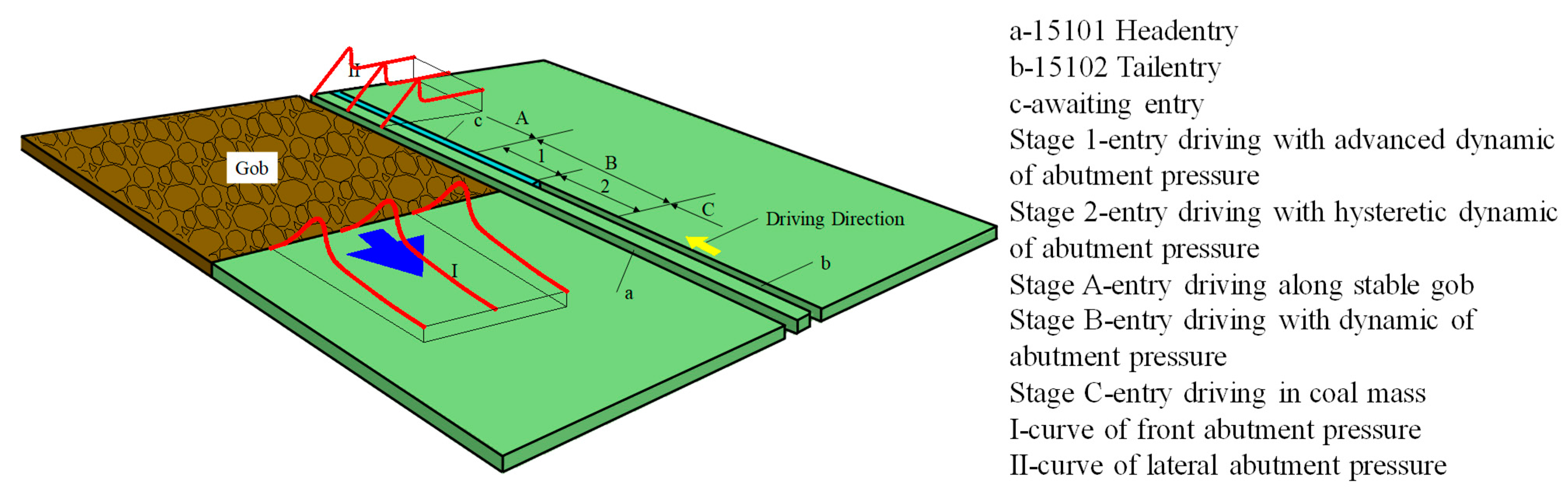
In recent years, with the rapid intensification of mining activities in coal mines, the balance between mining and development has become increasingly fragile. In order to solve the contradiction between fast mining and slow development, gob-side entry driving near an advancing working face (NAWF) has been applied to numerous coal mines in China and has emerged as an important means to address this challenge. As illustrated in Figure 1, when preparing for the subsequent working face through sequential mining, the entry must be advanced toward the retreating face through three stages: the stage of driving in the coal mass (Stage C), the stage of driving with dynamic abutment pressure (Stage B), and the stage of driving along the stable gob (Stage A). Stage B, in particular, is susceptible to significant deformation due to the influence of dynamic abutment pressure, which can adversely affect production operations. Consequently, determining the appropriate coal pillar width and implementing effective control measures pose a substantial challenge for gob-side entry driving near an advancing working face [1,2].

Figure 1.
Position of gob-side entry driving near an advancing working face.
Traditional gob-side entry driving typically involves advancing the tunnel along the edge of a stabilized mined-out area [3,4,5,6,7]. Gob-side entry driving near an advancing working face involves excavating the tunnel along the edge of the previously mined area with a narrow coal pillar left in advance of the adjacent working face, where the width of the coal pillar significantly influences the stability of the surrounding rock mass. The widely applied analytical approach for coal pillar design is the Wilson formula, which is based on the assumption of coal pillar elasticity. It is primarily suited for conditions of low stress and in the context of hard rock formations [8,9]. Salamon et al. [10], drawing from extensive data on multiple coal pillars in South African mines, proposed empirical formulas for coal pillar strength varying with different width-to-height ratios (W/H). Field tests and studies [11] have confirmed that unreasonable design of coal pillar dimensions can lead to severe instability of the surrounding rock mass around the entry, thereby posing significant safety hazards. A wealth of research and practical experience demonstrate that during the process of driving entries along the gob, ensuring stability is predicated upon the majority of the load being borne by the solid coal body. Coal pillars, when subjected to prolonged high-stress conditions, undergo plastic flow deformation [12].
Numerical simulation techniques have progressively become a vital tool in studying the stability of coal pillars. Zhang, Li et al. employed FLAC software to examine the stress distribution within coal pillars of varying widths during the practice of excavating alongside gobs [13,14]. Wang et al. [15] investigated the micro-damage mechanisms of overlying residual coal pillars influenced by longwall mining in underlying seams, revealing the evolution and distribution of foundation stresses. Wu et al. [16] utilized UDEC to simulate the natural deformation of entries in coal pillars and the distribution of fractures, examining the extension of cracks in coal pillars under dynamic abutment pressure and proposing principles for controlling narrow coal pillars. The double-yield model in FLAC has proven capable of reasonably simulating the stress–strain evolution process within gob areas, often yielding more detailed and realistic information compared to theoretical analyses and empirical methods [17]. Li et al. [18] introduced a numerical approach to coal pillar design, employing the double-yield model to simulate the mined-out area. Jaiswal et al. [19] conducted a back-analysis on various stability conditions of coal pillars in Indian coal mines, applying a strain-softening model to describe the stress–strain behavior of the coal pillars. Li et al. [20,21] noted that the Salamon model has a broader application range and utilized the double-yield constitutive model within the finite difference software FLAC to simulate the unique loading mechanism of caved rock in gob areas. The stress distribution obtained from the established numerical gob model agreed essentially with theoretical study results, confirming the rationality and reliability of the model.
Aside from leaving an appropriately sized coal pillar, the stability control of gob-side entry driving near an advancing working face is also critically dependent on effective techniques for surrounding rock control. Yu et al. [22] investigated the functional relationship between the deformation of surrounding rock in the advancement stage of the entry and the mining face, determining the timing for driving each section of the tunnel and the support parameters. This study put forth the principle of segmented control and a technique for robust roof support, thereby contributing to enhanced management of ground conditions during gob-side entry driving. Wang et al. [23] conducted research on the deformation patterns of surrounding rock and control techniques in gob-side entry driving adjacent to an active working face. The work proposed a novel ground control strategy combining the use of narrow coal pillars with high deformation capacity roof bolts, effectively addressing the challenges in maintaining rock stability during this complex mining operation. Weakening the strength of the overhanging roof and inducing fragmentation in the roof strata are vital measures to mitigate the impacts of hard and highly dynamic roof conditions on the stability of entries [24]. Chen et al. [25] investigated the effects of secondary stresses induced by working face extraction on the propagation of hydraulic fractures and proposed roof and surrounding rock control strategies combining hydraulic fracturing with roof cutting for depressurization. Yang et al. [26] delved into the mechanisms of directional blasting and its associated calculation formulas, introducing a method of directional blasting for cutting roof control. In many Chinese mines, complex and difficult entry support challenges persist. For such driving entries, the adoption of a holistic approach known as ‘cooperative control strategies’ serves as an integrative strategy. The merit of cooperative control strategies lies in their ability to maximize the effectiveness of each control method, enabling them to complement one another, thereby proving applicable in entries severely impacted by dynamic abutment pressure [27,28,29,30,31].
This study, taking Xizhang Coal Mine as a case, employs numerical simulations and field experiments to establish the spatial and temporal relationship between the stability of the surrounding rock in gob-side entry driving near an advancing working face and coal pillar width. Ultimately, this research puts forward cooperative control strategies that include a narrow coal pillar, hydraulic fracturing roof cutting for pressure relief, and entry dynamic support for the tunnels. By establishing principal technical parameters, it furnishes a valuable reference for analogous projects in the future.
2. Case Study
2.1. Field Background
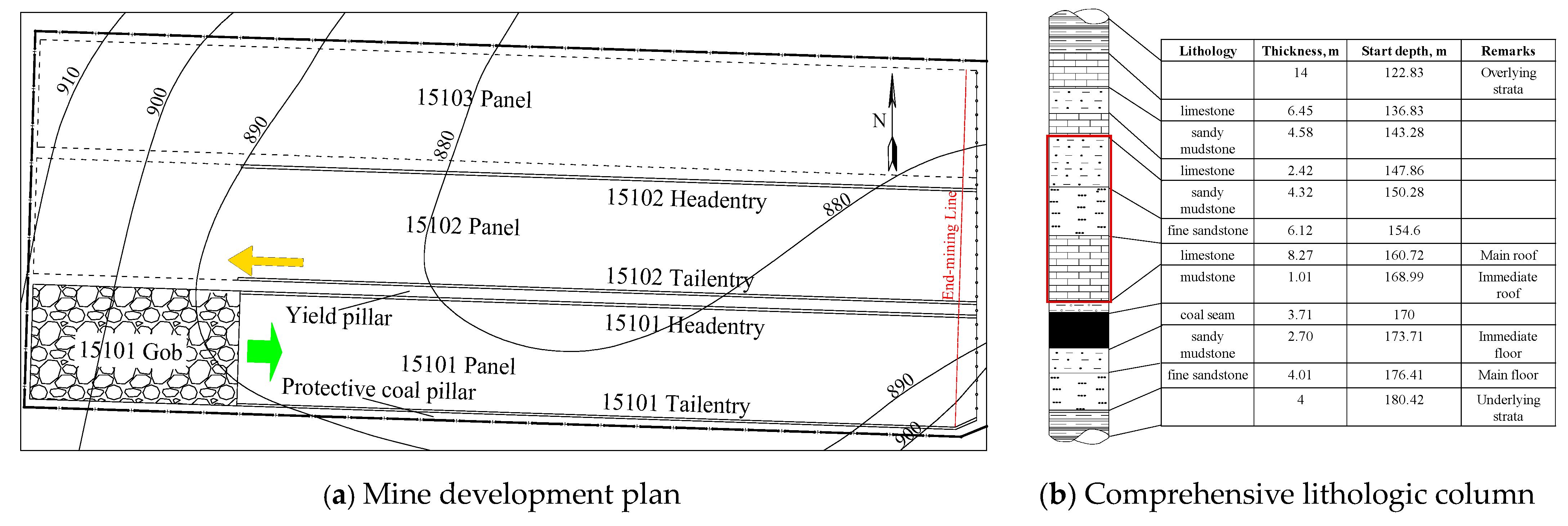
Xizhang Coal Mine is extracting the 15# coal seam in sequence through workings 15101, 15102, and 15103. The planar layout of the development is depicted in Figure 2. Currently, the 15101 working face is being mined. In accordance with the development and support succession requirements at Xizhang Coal Mine, the tailentry of the 15102 working face is being driven ahead, facing the extraction direction of 15101, with a coal pillar width of 15 m. The 15102 working face must be fully prepared before the extraction concludes in the 15101 working face. The 15101 working face has a width of 160 m and extends longitudinally for approximately 1250 m. The average depth of burial for the coal seam is around 170 m, with an average thickness of 3.71 m. The full-height mining technology of fully mechanized mining is adopted.
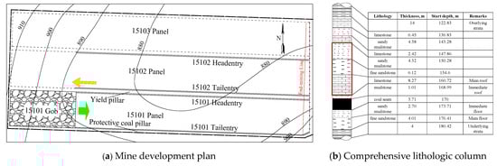
Figure 2.
Mine development plan and lithologic column.
The comprehensive lithologic column of the 15# coal seam is illustrated in Figure 2b. The immediate roof consists of mudstone, measuring 1.01 m thick, while the main roof is composed of K2 limestone, with a thickness of 8.27 m. Overlying the limestone is a composite roof formation made up of fine sandstone and sandy mudstone, totaling 10.44 m in thickness. In this composite section, the fine sandstone is situated beneath, directly connecting to the K2 limestone layer. In order to gain a more comprehensive understanding of the mechanical properties of surrounding rock for the purpose of this study, indoor experiments were conducted on rock core sampling, and three samples were tested for each specific rock unit. According to the test results, the mechanical properties of strata are shown in Figure 3. Specifically, the tensile strengths are recorded as 8.01 MPa for limestone, 4.94 MPa for fine sandstone, and 3.92 MPa for mudstone. Meanwhile, their respective compressive strengths are 95.86 MPa, 62.14 MPa, and 30.91 MPa. These values indicate a strong and stable roof that is resistant to collapse.
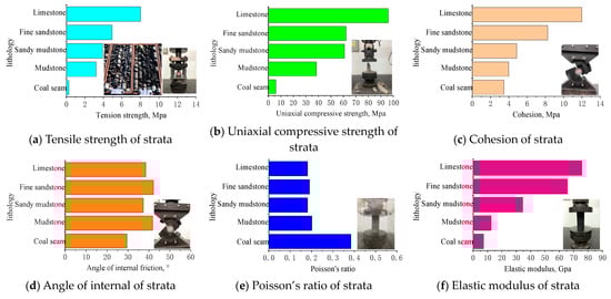
Figure 3.
Mechanical properties of strata.
2.2. Displacement Characteristics of Entry
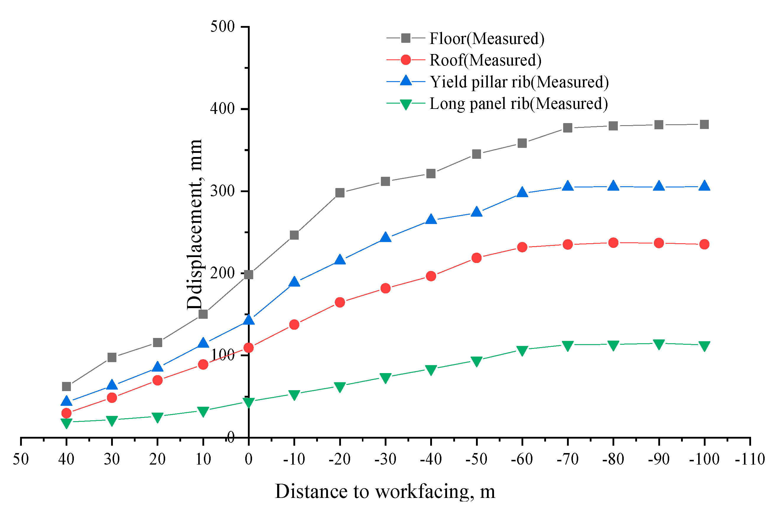
During the extraction of the 15101 working face and the development of the 15102 tailentry, select one key measuring point in the 15102 tailentry, which should be located more than 300 m ahead of the 15101 working face to ensure the complete capture of the impact of the near 15101 working face mining on the 15102 tailentry [32]. Permanent wooden stakes are installed on the top and bottom plates of the tunnel and on both sides of the measuring point. The displacements of the two sides and the top and bottom plates are recorded separately using a tape measure to extend and retract the measuring rod, and the results of this monitoring are illustrated in Figure 4. It can be seen that under the influence of the mining of the 15101 working face, the tailentry of the 15102 working face has a serious displacement at a distance from the heading end. The surrounding rock experienced the most intense displacement when it was located 40 m ahead to 20 m behind the working face undergoing extraction. Displacement rates slowed down from 20 m behind to 70 m behind the working face, and beyond 70 m to 100 m, the surrounding rock essentially ceased further deformation, stabilizing with minimal change. Ultimately, the maximum displacements recorded were 1121 mm for the floor heave, 601 mm for the roof, 783 mm for the coal pillar side, and 237 mm for the solid coal side, with the floor heave presenting the most severe issue, the entry side had to be enlarged and repaired. Consequently, scientific optimization of the gob-side entry driving NAWF process is imperative, necessitating the determination of an appropriate coal pillar width and the implementation of control technologies.
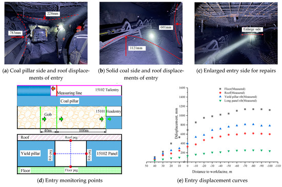
Figure 4.
Entry monitoring points and displacement.
3. Establishment of Numerical Analysis Model
3.1. Numerical Model and Simulation Scheme
3.1.1. Numerical Model
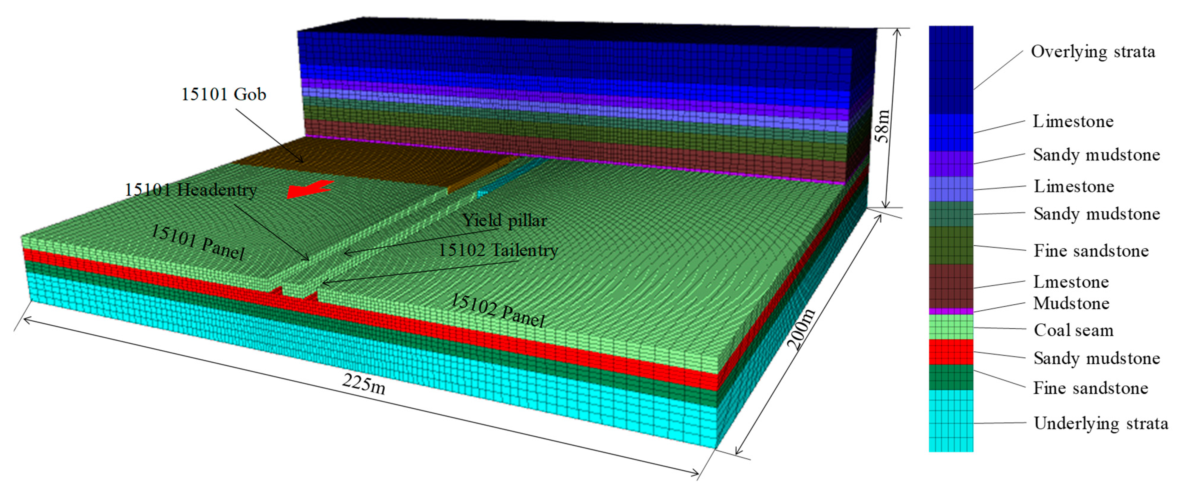
Based on the comprehensive lithologic column of strata, a FLAC3D numerical model was established, as illustrated in Figure 5. The model encompasses the 15101 working face, the 15102 working face, the coal pillar, and the entries. The model spans 225 m in length and 200 m in width, with a height of 58 m. Fixed deformation boundaries are applied to all sides except the top surface of the model. A lateral pressure coefficient of 1.2 is adopted. Rock and coal failure adhere to the Mohr–Coulomb model, while the gob follows the double-yield model.

Figure 5.
Numerical model.
3.1.2. Numerical Simulation Scheme and Measurement Scheme
This simulation analyzed four different coal pillar widths: 20 m, 15 m, 10 m, and 7 m. The computational steps for the model are as follows: ① calculation of the original rock stress state → ② development of the 15101 headentry → ③ development of the 15102 tailentry → ④ extraction of the 15101 working face.
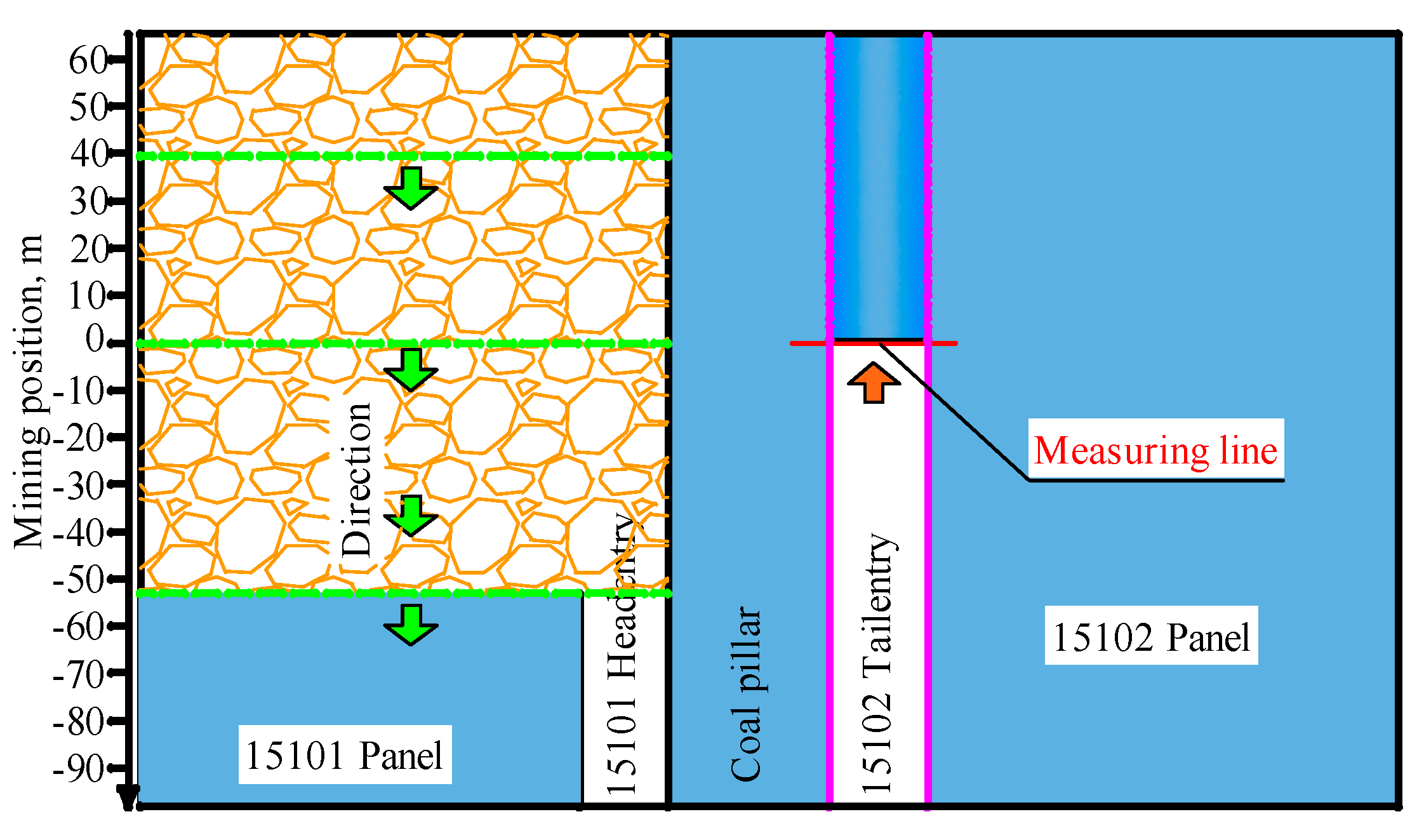
The survey lines for the model are positioned at the heading end of the 15102 tailentry, as shown in Figure 6. Taking this location as the origin (0 point), advancements of the 15101 working face toward the front of the survey line are considered positive, while advancements behind the survey line are considered negative. Data are collected to analyze the impact of 15101 working face extraction on the stability of the coal pillar and the 15102 tailentry.
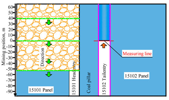
Figure 6.
Measurement scheme.
3.2. Numerical Simulation of Mechanical Properties of Rock
To ensure the reliability of numerical study results, a thorough assessment of the rock mass mechanical properties is essential. Laboratory tests conducted indoors, such as uniaxial compression and Brazilian splitting tests to obtain parameters of rock samples, do not necessarily represent the deformation characteristics of rock masses. Research indicates that the stiffness of numerical models averages 0.496 times that of laboratory samples, while the uniaxial compressive strength of the models averages 0.284 times the laboratory-measured strength [33,34]. For coal–rock masses, the elastic modulus, cohesion, and tensile strength can be estimated to be within 0.1 to 0.25 times the results from indoor experiments, with Poisson’s ratio taken as 1.2 to 1.4 times the indoor test results [35]. Accordingly, the mechanical parameters used in the model for the coal and rock masses were estimated, with the elastic modulus, cohesion, and tensile strength set at 0.2 times the laboratory values and the Poisson’s ratio at 1.2 times the indoor experimental results. The final coal and rock mass mechanical parameters applied in the model are summarized in Table 1.

Table 1.
Key rock parameters used in the numerical model.
3.3. Double-Yield Model of Gob Area
The bearing capacity of the caved surrounding rocks in the gob has a significant influence on the distribution law of the supporting stress induced by dynamic abutment pressure. The greater the bearing capacity of the surrounding rocks, the less pronounced the manifestation of the extraction-induced supporting stress becomes. At the edge of the gob, the vertical stress is essentially zero. As the distance from the gob increases to 0.12–0.6 times the depth of coal seam burial, the stress in the gob area generally recovers to the level of the original rock stress, with the gob materials exhibiting strain hardening characteristics [36]. Consequently, to better assess the impact of gob stress recovery and the load-bearing characteristics of the collapsed zone’s strata on the extraction-induced supporting stress during mining, the double-yield model is commonly employed in FLAC3D simulations to capture the strain-hardening behavior of gob materials.
Based on the Salamon model [37], the material elements in the gob conform to the following equations:
where is the expansion coefficient of the gob; is the maximum strain of the gob material; is the height of the caving zone in m; is the thickness of the coal seam mining in m; is the initial vertical stress at the top of the coal seam in MPa; and is the initial modulus of the mined-out area material in GPa. The height of the caving zone is generally 2–8 times the thickness of the coal seam mining [38]. According to the geological conditions of the working face, the thickness of the coal seam mining is 3.7 m, and the height of the caving zone is 9.27 m. Substituted into Formulas (1)–(4), the expansion coefficient of the gob material is 1.42, the maximum strain is 0.24, the initial vertical stress at the top of the coal seam is 4.2 MPa, and the initial modulus of the gob material is 22.4 GPa. The stress–strain relationship of the gob material is shown in Table 2.
Table 2.
The stress–strain relationship for the double-yield model.
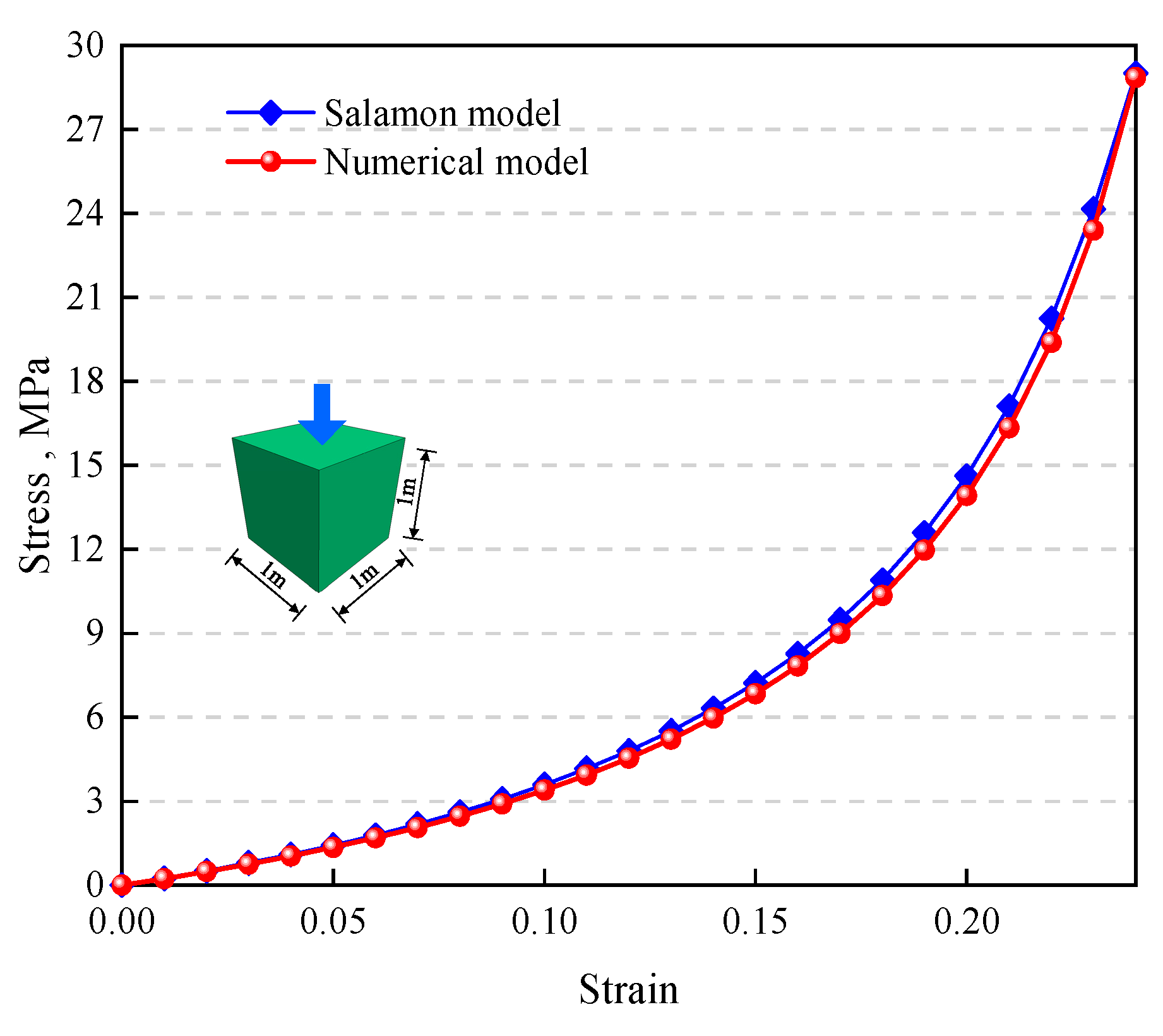
To validate the reasonableness and accuracy of the parameters in the FLAC3D calculation using the double-yield model, a single-element calibration method is employed. The unit block size is set at 1 m × 1 m × 1 m, with fixed deformation applied around the periphery and at the bottom of the model. A constant vertical velocity load is imposed at the top of the model. Using the trial-and-error method for inversion calculations, the primary mechanical parameters for the double-yield gob material in the FLAC3D computation are determined to be a bulk modulus of 1.5 GPa, a shear modulus of 1 GPa, an internal friction angle of 3°, a dilation angle of 8°, and a density of 1650 kg/m3. The comparison of numerical calculation results with the stress–strain relationship of gob materials from the Salamon model is illustrated in Figure 7.

Figure 7.
Comparison of the stress–strain curves between the numerical model and the Salamon model.
To verify the reliability of the double-yield model for the gob, a simulation was conducted to illustrate the distribution of vertical stress in the gob during the extraction process of the 15101 working face, as shown in Figure 8. At the edge of the 15101 gob, the vertical stress is merely 0.25 MPa; it gradually increases toward the center of the gob, reaching and stabilizing at approximately 4.1 MPa, around 80 m away from the gob edge, which restores to the state of initial stress. The calculated stress distribution in the gob by the model is in good agreement with results from other researchers [13,14]. Hence, the calibrated parameters can be used for modeling the coal and rock mass in this study.
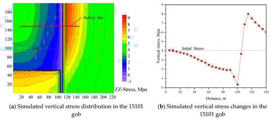
Figure 8.
Vertical stress distribution of the 15101 gob after the modeling process.
3.4. Validation of Simulation Model Parameters
To validate the reliability of the global model, in situ deformation data collected from the surface of the driving entries along the gob are utilized to calibrate the coal and rock layer parameters. Figure 9 displays a comparison between the measured displacement data and the numerically simulated displacement of the entry after the extraction of the 15101 working face, with a coal pillar width of 15 m. The curve derived from numerical simulation aligns well with the actual measurement data, thereby validating the rationality and reliability of the numerical model.
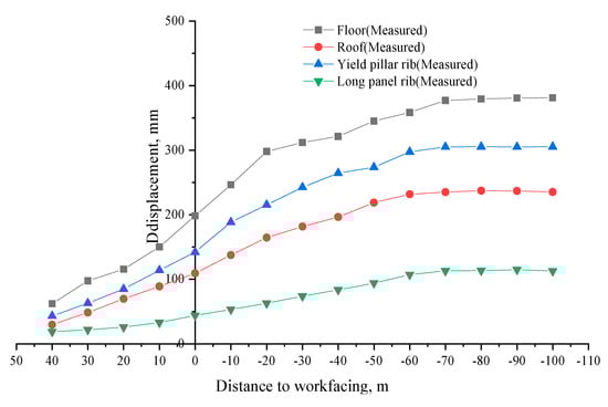
Figure 9.
Simulated and measured entry displacements.
4. Simulation Results of Gob-Side Entry Driving NAWF
4.1. The Influence Range of 15101 Working Face Mining
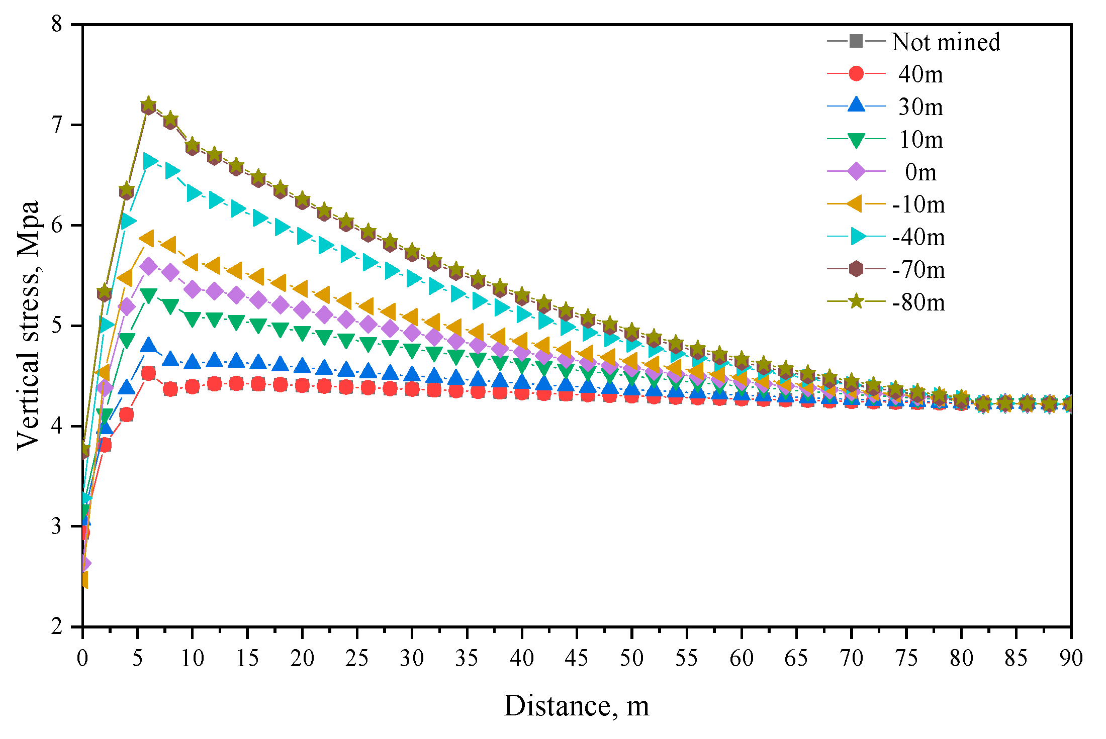
Figure 10 illustrates the variation curve of lateral supporting stress in the process of 15101 working face mining. It can be seen that during the extraction process, the lateral supporting stress curves exhibit a single-peak distribution, peaking at a distance of 6 m from the gob. Beyond 75 m from the gob, the stress in the surrounding rock essentially returns to the level of the original rock stress.
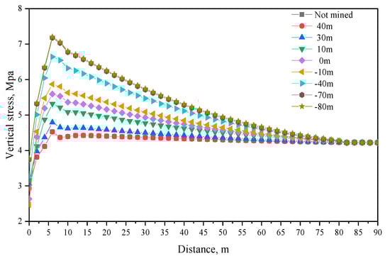
Figure 10.
Lateral supporting pressure in the process of mining.
During the extraction of the 15101 working face, the entry begins to be affected by dynamic abutment pressure 30 m ahead of the working face. As the extraction progresses, the vertical stress gradually increases, with a substantial growth in the peak vertical stress occurring 10 m ahead of the measurement line’s position. This rapid increase persists until the measurement line is located 40 m behind the working face. By the time the measurement line is 70 m behind the working face, the lateral supporting stress starts to stabilize. The peak stresses in the surrounding rock before any mining influence, when the working face is 30 m ahead, at the intersection of development, and after the lateral supporting stress stabilizes, are 4.6 MPa, 4.7 MPa, 5.6 MPa, and 7.5 MPa, respectively. The stress concentration coefficients are 1.12, 1.14, 1.36, and 1.83, respectively. A comprehensive analysis reveals that the zones 30 m ahead of and 70 m behind the working face are where mining-induced stresses exert their most intense impact.
4.2. Failure Characteristics of the Coal Pillar during Gob-Side Entry Driving NAWF
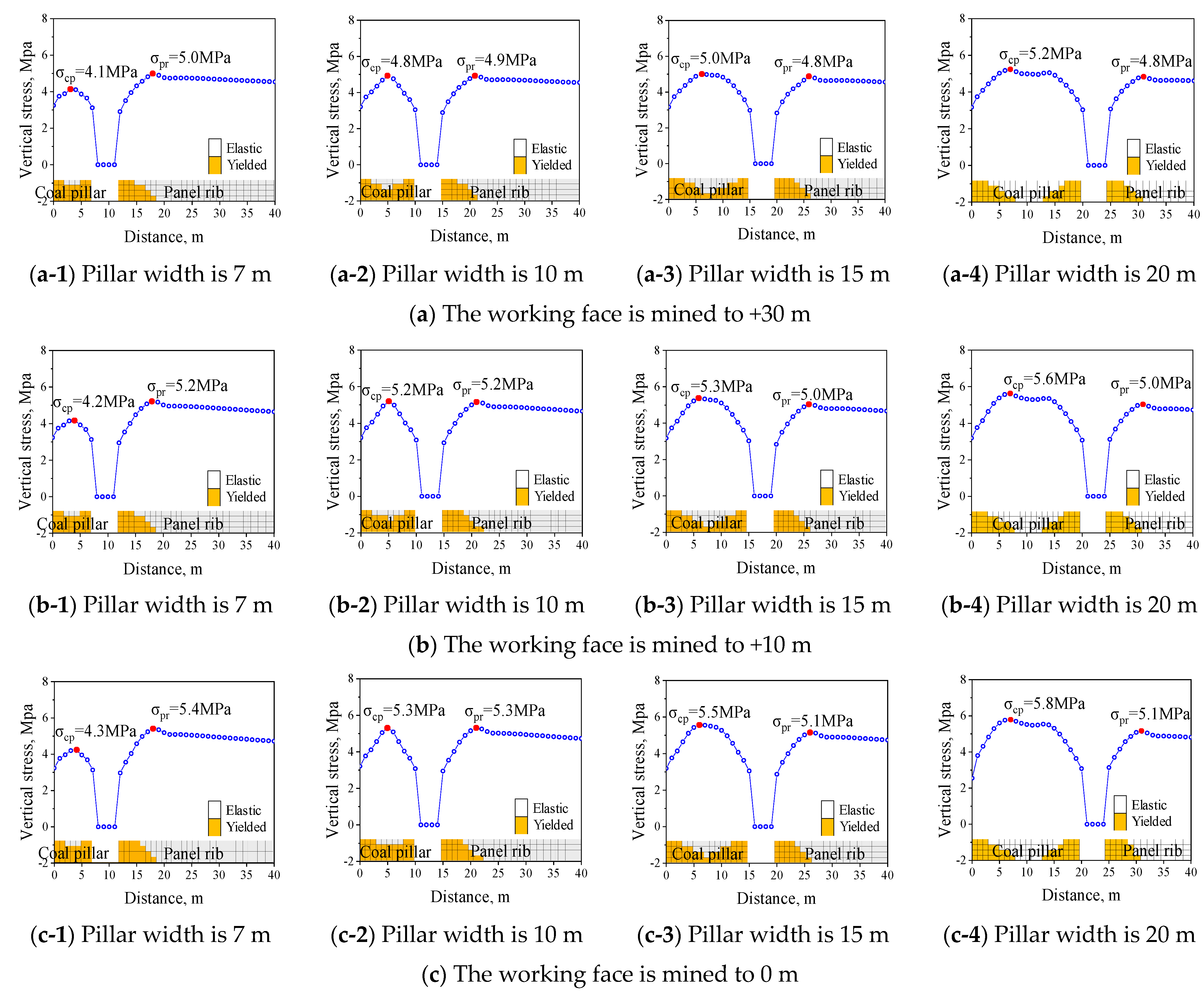
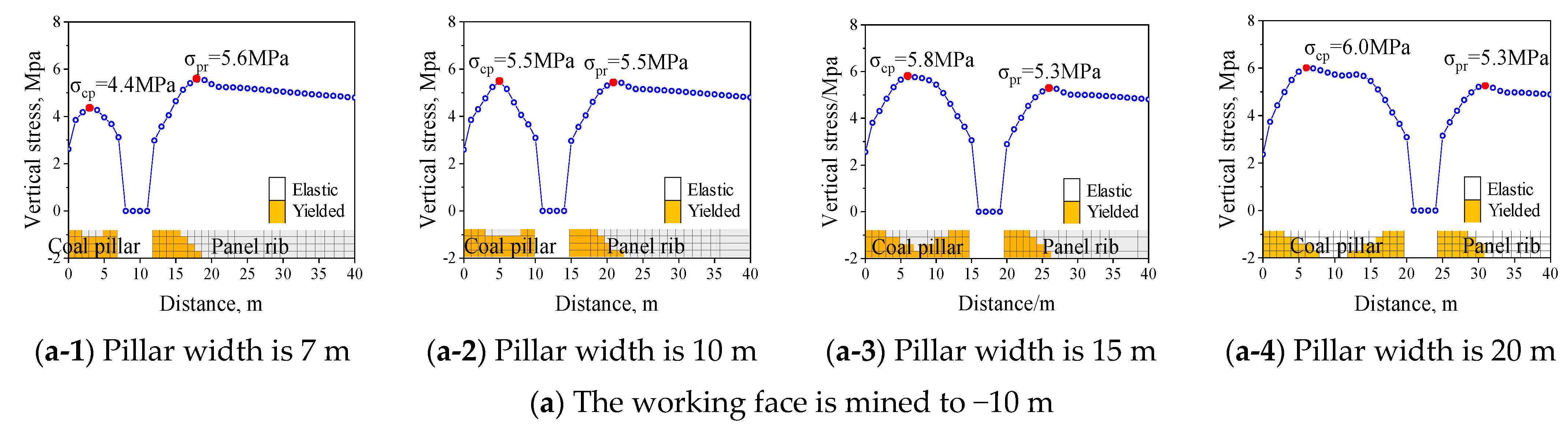
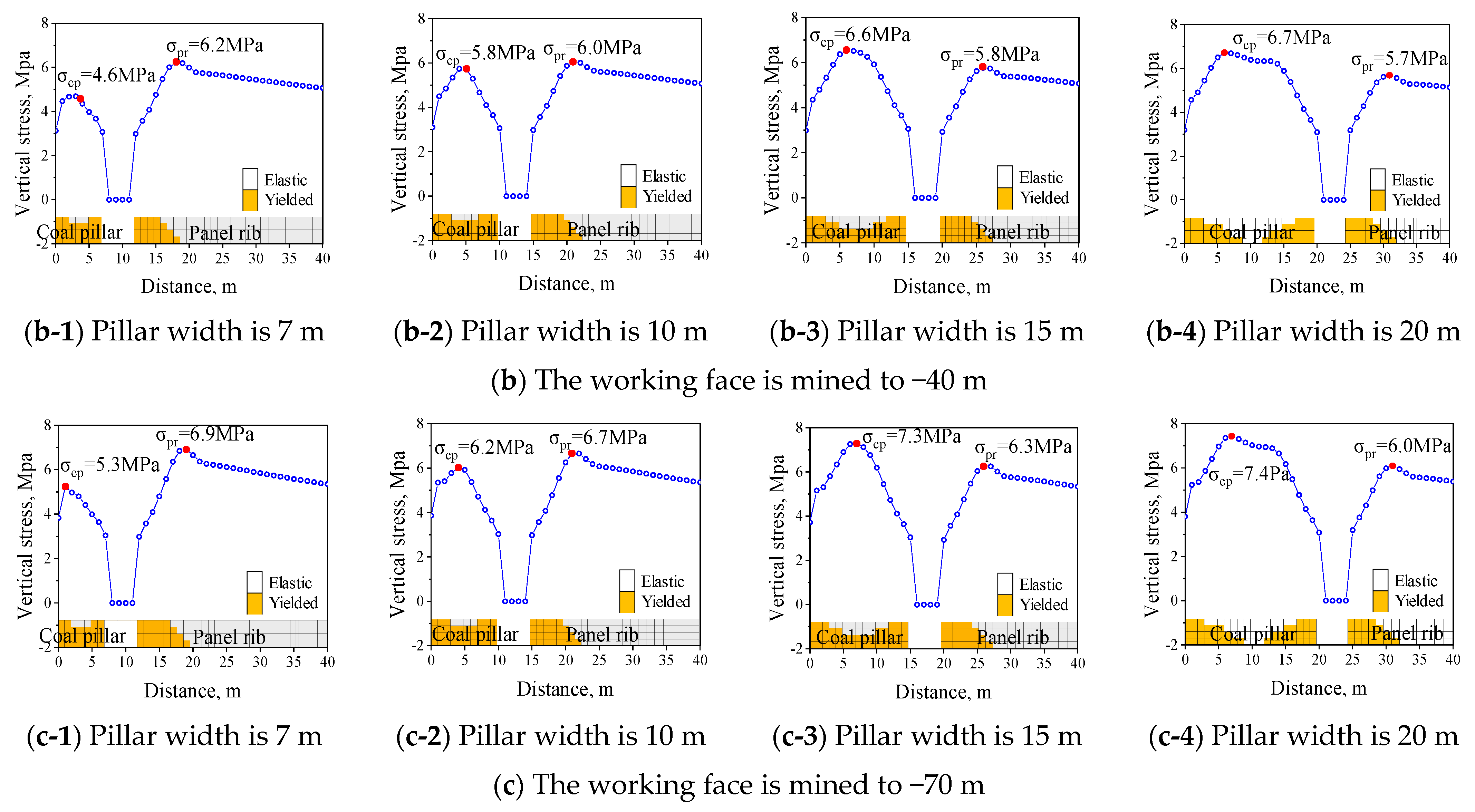
When the working face advances to 30 m, 10 m, and 0 m under different widths, the failure characteristics of the coal pillar are shown in Figure 11. When the working face advances to −10 m, −40 m, and −70 m, the failure characteristics are shown in Figure 12.
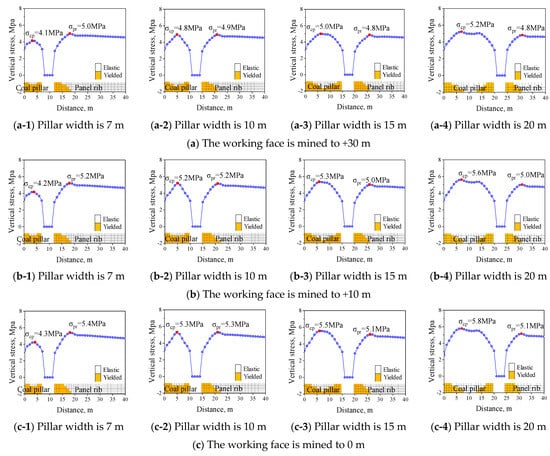
Figure 11.
The characteristics of surrounding rock failure at different advancing distances of the working face under advanced influence.
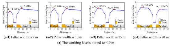
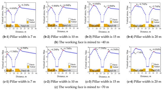
Figure 12.
The failure characteristics of surrounding rock with different advancing distances in the working face under lag influence.
For coal pillar widths of 20 m, 15 m, 10 m, and 7 m, when the working face advances to +30 m (30 m ahead of the working face), the maximum vertical stresses within the coal pillars are 5.2 MPa, 5.0 MPa, 4.8 MPa, and 4.7 MPa, respectively. When the working face progresses to 0 m, these stresses rise to 5.8 MPa, 5.5 MPa, 5.3 MPa, and 4.3 MPa, respectively.
When the working face progresses to −70 m (70 m behind the working face), these stresses rise to 7.4 MPa, 7.3 MPa, 6.2 MPa, and 5.3 MPa, respectively. Throughout the extraction process, from the start of mining influence to its cessation, the stress increments within the coal pillars are 42%, 46%, 29.17%, and 29.26%, respectively. Meanwhile, within the solid coal body, the corresponding stress increments over the same period are 12.5%, 23.81%, 36.73%, and 38%, respectively.
When the coal pillar width is 20 m, the coal pillar does not fully fail, retaining an intact elastic zone within. For coal pillar widths of 15 m, 10 m, and 7 m, the characteristics of the supporting stress and plastic zones suggest that while the pillars are damaged, they have not completely fragmented. Drawing upon the interaction principle of surrounding rock and support [39], the plastic zones in these instances still contribute to load-bearing capacity.
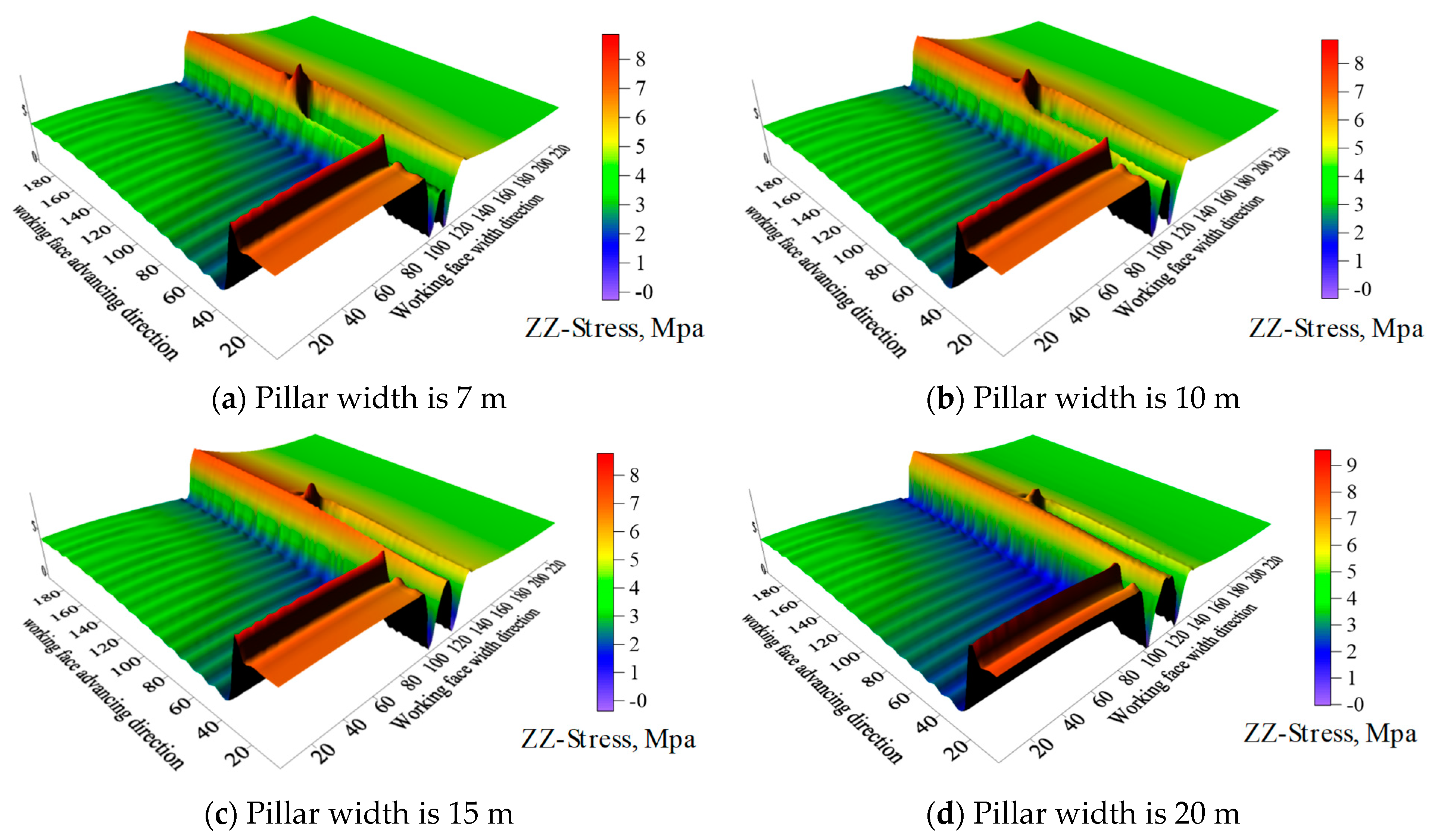
4.3. Determination of Coal Pillar Width
Figure 13 illustrates the three-dimensional contour map of vertical stress when the mining face 15101 reaches the −70 m level, depicting conditions with coal pillar widths of 7 m, 10 m, 15 m, and 20 m. It can be observed that when the coal pillar widths are 20 m, 15 m, 10 m, and 7 m, the peak stresses within the coal pillars are 7.4 MPa, 7.3 MPa, 6.7 MPa, and 5.3 MPa, respectively. The corresponding stress concentration factors are 1.80, 1.78, 1.63, and 1.29, respectively. Notably, the 7 m coal pillar exhibits the minimum vertical stress.
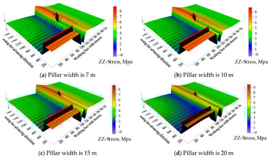
Figure 13.
Three-dimensional cloud maps of vertical stress of coal seam at −70 m coal pillar.
The aforementioned simulation results indicate that when coal pillar widths are 20 m, 15 m, and 10 m, the internal vertical stresses are excessively high, causing the pillars to remain under high-stress conditions for extended periods, which are conducive to plastic flow deformation. Conversely, with a coal pillar width of 7 m, the peak stress within the pillar is only slightly higher than the original rock stress, and the stress within the solid coal exceeds that in the coal pillar. Under these circumstances, the pillar is subjected to lower loads, and the surrounding rock of the entry is in a relatively low-stress environment. Taking into account the stress state of the coal pillars, the stability of the surrounding rock, and other factors, the optimal coal pillar width is determined to be 7 m.
5. Cooperative Control Strategies of Gob-Side Entry Driving NAWF
In the subsequent mining process, the conclusions derived from the above research were utilized to optimize the width of the 15103 tailentry coal pillar. The cooperative control strategies comprising a narrow coal pillar, hydraulic fracturing roof cutting for pressure relief, and entry dynamic support were proposed for the 15103 tailentry.
5.1. Pressure Relief Scheme of Hydraulic Fracturing Roof Cutting
According to the roof rock characteristics of the 15# coal seam and the lateral supporting stress features of the working face 15102, the hard limestone roof (Figure 3b) is also a significant factor contributing to the large displacement of the entry. To ensure the stability of the 15103 tailentry during the extraction of the 15102 working face, hydraulic fracturing strategies were applied to the roof cutting and relieve pressure.
The focus of hydraulic fracturing for cutting the roof is on the K2 limestone and fine sandstone layers above the coal seam, ensuring that the height of the caved rock strata is sufficient to fill the gob, thereby supporting the bending displacement of the overlying strata and generating widespread high supporting pressures. The determined cutting height is set at 20 m.
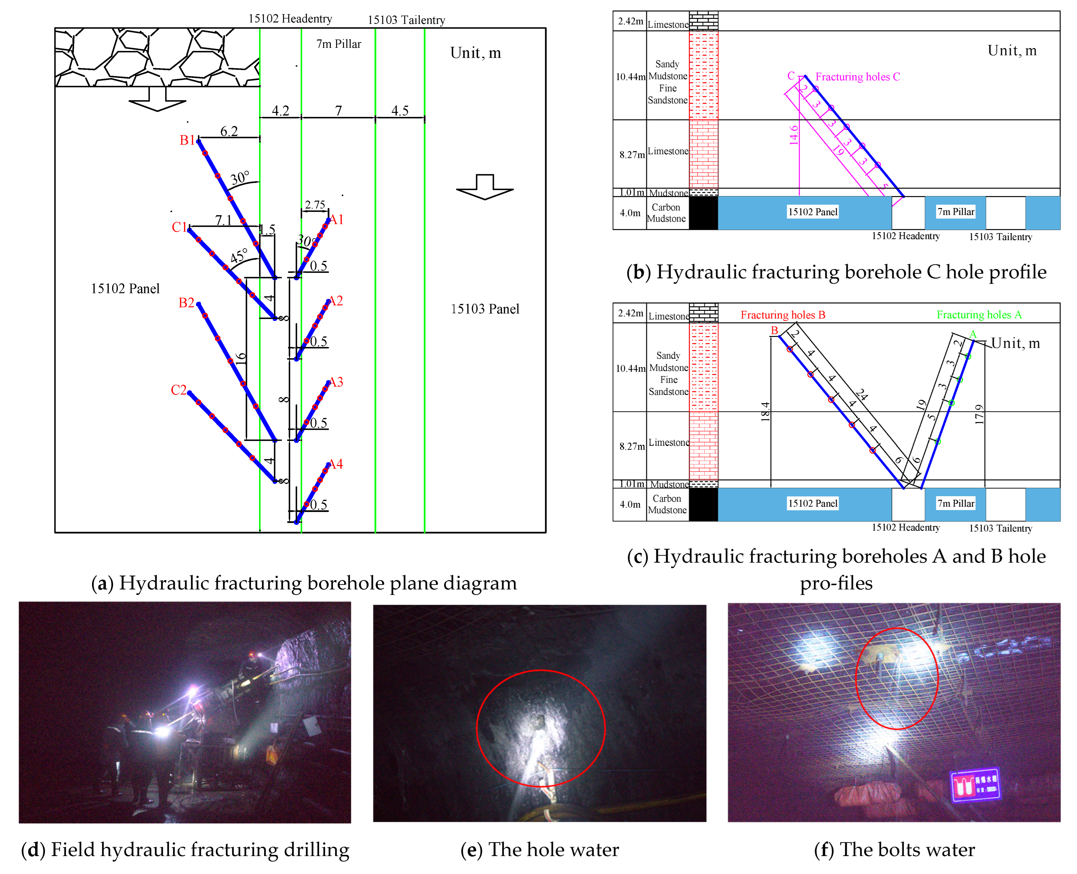
Figure 14 shows the drilling parameters of hydraulic fracturing roof cutting, and the drilling diameter is Φ65 mm. The vertical elevation angle of hole A is 75°, the horizontal deviation angle is 30°, the hole depth is 19 m, and the vertical height of the terminating hole position is 17.9 m. The vertical elevation angle of hole B is 50°, the horizontal deflection angle is 30°, the hole depth is 24 m, and the vertical height of the terminating hole is 18.4 m. The vertical elevation angle of hole C is 50°, the horizontal deflection angle is 45°, the hole depth is 19 m, and the vertical height of the terminating hole is 14.6 m. The hole spacings of holes A, B, and C are 8 m, 16 m, and 16 m, respectively. The fracturing times of each hole are four times, five times, and five times, respectively.
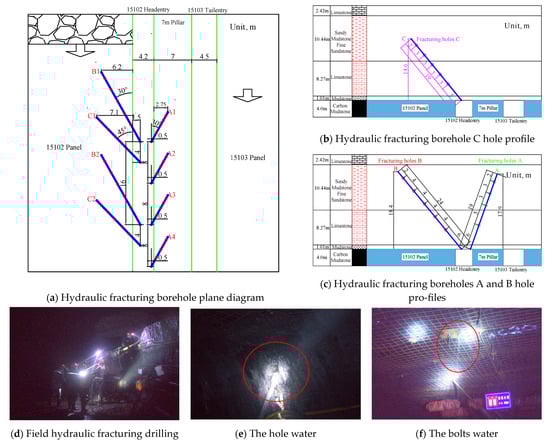
Figure 14.
Hydraulic fracturing borehole layout of 15102 headentry.
5.2. Determination of Dynamic Segmented Support Scheme
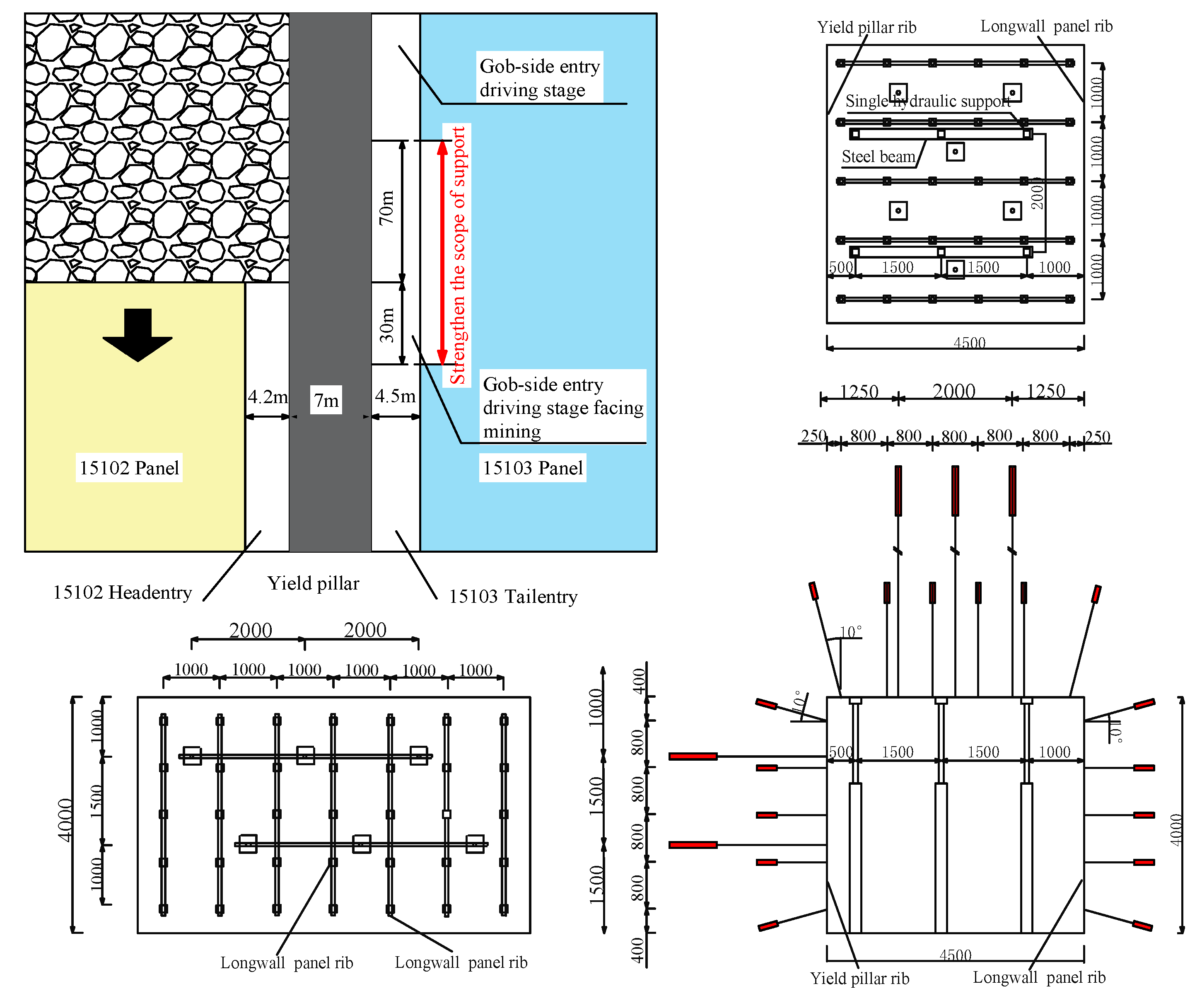
For the 15103 tailentry, a 7 m coal pillar width is reserved for gob-side entry driving NAWF. The cross-section of the entry measures 4500 mm in width by 4000 mm in height, and the cooperative support of the bolt and anchor cable is shown in Figure 15. The roof and two sides use Φ22 × 2200 mm left-handed screw steel anchors with a row spacing of 800 × 1000 mm. The roof anchor cable is Φ21.6 × 6300 mm, and the row spacing is 2000 × 1000 mm. There is no anchor cable on the solid coal side. The anchor cable of the coal pillar side uses a Φ17.8 × 4300 mm mine anchor cable, which is placed between two rows of anchor bolts. Each row is arranged with a row spacing of 1000 mm. The upper anchor cable is 1000 mm away from the roof. The middle anchor cable is 2700 mm away from the roof, and the spacing between the upper and lower anchor cables is 1500 mm.
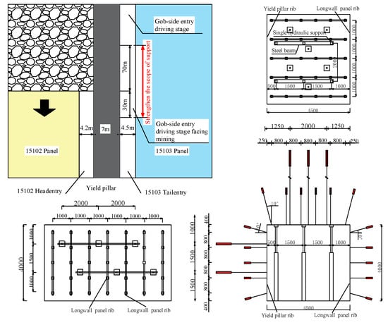
Figure 15.
Dynamic support scheme of gob-side entry driving NAWF.
Single hydraulic props are employed to provide reinforcement for sections of the 15103 tailentry that are 30 m ahead and 70 m behind the disturbed segment influenced by the adjacent working face’s dynamic of abutment pressure. Three single hydraulic props are installed per row, with a row spacing of 2000 mm. The enhanced support dynamically shifts backward along the 15103 tailentry as the working face progresses.
5.3. Field Effect
5.3.1. Hydraulic Fracturing Effect
In the process of hydraulic fracturing, the initiation pressure of each fracturing point is in the range of 13–23 MPa. After high-pressure water fracturing rock, the pressure will decrease, the stable pressure is in the range of 10–18 MPa, and the average pressure drop is 1–3 MPa. The existence of pressure drop proves that high-pressure water effectively breaks hard rock. At the same time, the phenomenon of adjacent hole water and adjacent anchor cable water outlet occurs during on-site fracturing.
The hydraulic fracturing borehole was inspected using the DC-10 mining borehole imaging trajectory integrated detection device after the fracturing. Taking hole A as an example, the detection results are shown in Figure 16. It can be observed that fractures are present at depths of 6 m, 11 m, 14 m, and 17 m within the borehole. The cracks are mainly axial cracks and circumferential cracks. Most of the annular cracks are inclined annular cracks, and only a small number are non-closed arc cracks. The extensive spread of these fractures exerts a significant disruptive effect on the K2 limestone roof overlying the 15# coal seam.
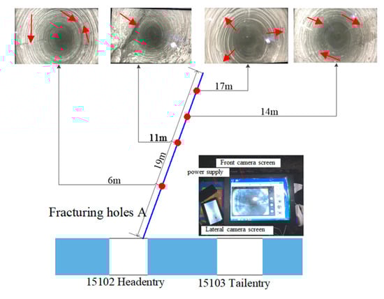
Figure 16.
Surrounding rock cracks after hydraulic fracturing drilling.
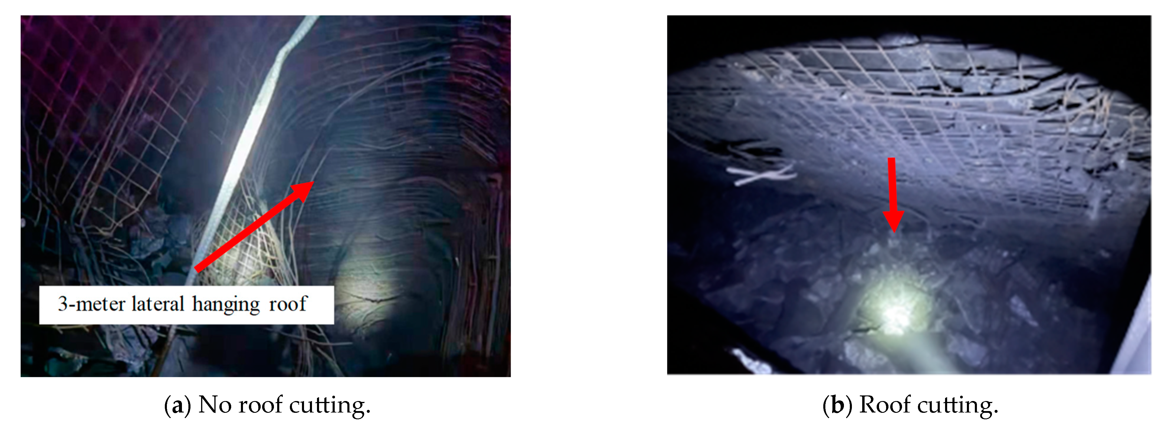
Figure 17 illustrates the cutting condition of the roof before and after the cutting process for the 15103 headentry. When cutting was not performed during the extraction of the 15102 working face, the lateral roof of the gob area did not collapse in synchronization with the advancing working face (Figure 17a), resulting in a 3 m lateral hanging roof alongside the coal pillar. Following hydraulic fracturing and caving, the roof at the end of the gob promptly collapses in line with the advancing working face, demonstrating that hydraulic fracturing facilitated the caving of the roof (Figure 17b).
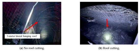
Figure 17.
Roof caving characteristics before and after roof cutting in 15102 headentry.
5.3.2. Entry Displacement
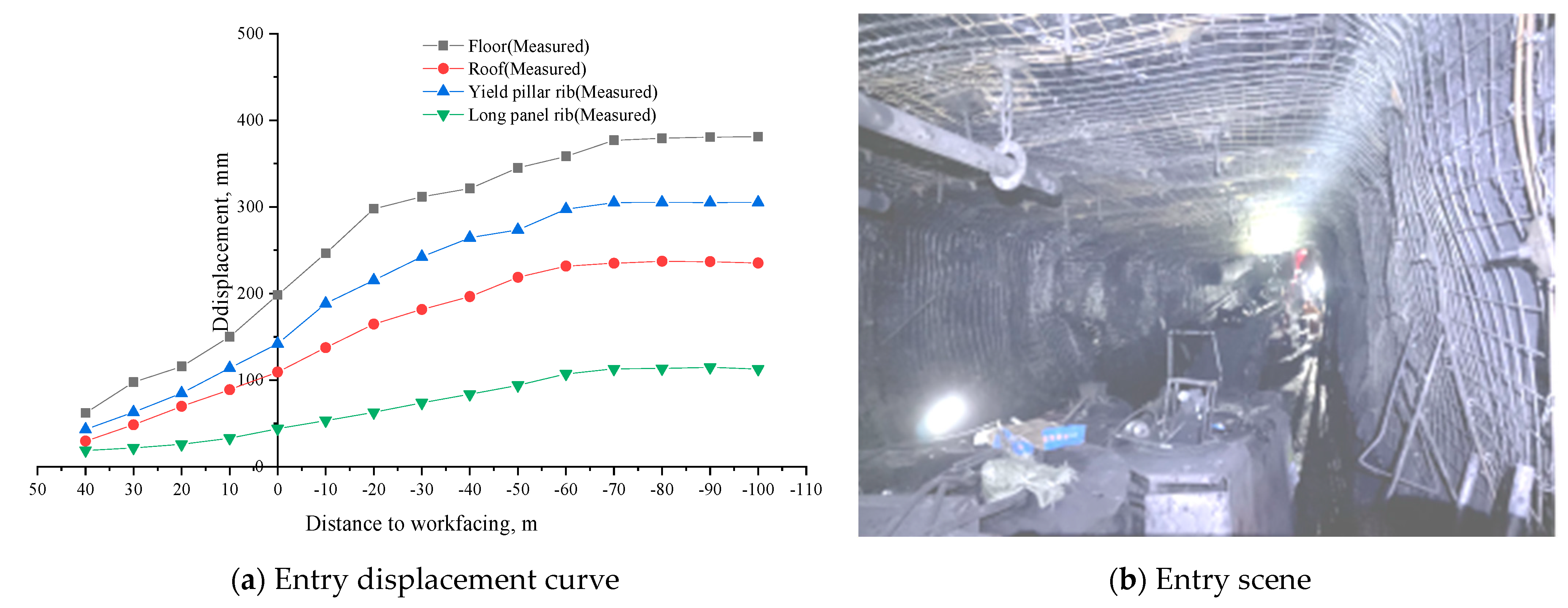
Field monitoring of the surrounding rock displacement during the development of the 15103 tailentry was conducted, and the control effectiveness is illustrated in Figure 18.
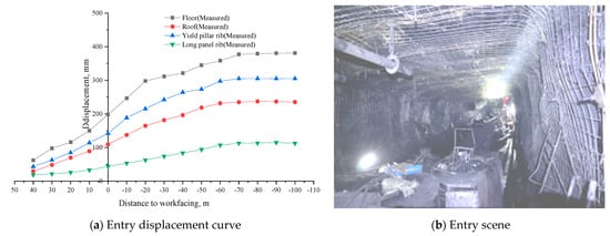
Figure 18.
Control effect of 15103 tailentry.
It can be seen from Figure 18a that after the 15103 tailentry adopts the cooperative control strategies, the displacement of the tailentry is reduced by 60% to 70% when it is 30 m ahead of the 15102 working face. When the 15102 working face is mined to the intersection with the end of the tailentry, the amounts of floor heave, roof subsidence, coal pillar side movement, and real media side movement are 198 mm, 109 mm, 142 mm, and 44 mm, respectively, which are reduced by 71.31%, 72.55%, 57.00%, and 65.90%, respectively. When the tailentry lags behind 15102 working face 0 m-70 m, the displacement of the entry is reduced by 60% to 70%. When the tailentry is 70 m behind the 15102 working face, the displacement of the entry is basically stable. Finally, the amounts of floor heave, roof subsidence, coal pillar displacement, and real media displacement are 381 mm, 228 mm, 305 mm, and 87 mm, respectively. The displacements of the entry are reduced by 66.01%, 62.06%, 61.05%, and 63.30%, respectively. The improvement in entry stability is also observed in the field. As depicted in Figure 18b, a photograph taken within the entry at a distance from its end after support installation shows that the 15103 tailentry experiences negligible displacement in the section that precedes the 15102 working face.
6. Conclusions
The numerical simulation and field test methods are used to study the significant deformation of gob-side entry driving in Xizhang Coal Mine, and the following conclusions are drawn:
(1) Field tests indicate that when the coal pillar width between the 15102 tailentry and the 15101 working face is 15 m, the displacements of the entry floor, roof, coal pillar side, and solid coal side are 1121 mm, 601 mm, 783 mm, and 237 mm, respectively; the displacement of the entry floor is the most serious.
(2) The results of the simulation indicate that the influence range of the surrounding rock pressure caused by mining in the upper section of gob-side entry driving is 30 m ahead and 70 m behind. When the coal pillar width is set at 15 m, the increase in stress within the coal pillar is less than that within the solid coal body, indicating a higher load on the coal pillar. Conversely, when the coal pillar width increases from 7 m to 20 m, the internal stress of the coal pillar increases continuously, while the internal stress of the solid coal decreases continuously. It is estimated that the reasonable coal pillar width should be 7 m, which is subjected to a lower load.
(3) The cooperative control strategies comprising a narrow coal pillar and hydraulic fracturing roof cutting for pressure relief are proposed. The field application shows that the hydraulic fracturing roof cutting successfully destroyed the integrity of the K2 limestone roof of the 15 # coal seam and effectively completed the pressure relief. The displacements of the surrounding rock of the 15103 tailentry are 66.01%, 62.06%, 61.05%, and 63.30% lower than those of the 15102 tailentry in the same period. This finding for the gob-side entry driving NAWF in this study can potentially be applied to other similar projects.
Author Contributions
Conceptualization, W.W. and T.W.; methodology, J.B. and W.W.; software, W.W. and T.W.; validation, H.X. and W.W.; formal analysis, T.W.; investigation, W.W.; resources, W.W.; data curation, W.W.; writing—original draft preparation, T.W.; writing—review and editing, J.L.; visualization, T.W., H.X. and X.W.; supervision, H.X., W.W. and J.L.; project administration, W.W., G.F., X.W. and J.B.; funding acquisition, W.W. and J.B. All authors have read and agreed to the published version of the manuscript.
Funding
This research has been supported by the National Natural Science Foundation of China (Grant No. 52204150), the Fundamental Research Program of Shanxi Province (202103021223051), the Joint Fund Project of the National Natural Science Foundation of China (U21A20107), the Youth Foundation of TYUT (2022QN069), the Distinguished Youth Funds of the National Natural Science Foundation of China (51925402), the Science and Technology Innovation Program Project of Higher Education Institutions in Shanxi Province (2021L065), and the Tencent Foundation or XPLORER PRIZE. The authors thank Xizhang Coal Mine for their support during the field test.
Data Availability Statement
The data presented in this study are available on request from the corresponding author. The data are not publicly available due to ongoing proprietary research and analysis, which requires the preservation of data integrity and confidentiality for further in-depth studies.
Conflicts of Interest
Author Wenda Wu works part-time at the company Xuzhou Coal Mining Group Co. Author Jinhu Liu was employed by the company Xuzhou Coal Mining Group Co. Author Haiyun Xu was employed by the company Shanxi Changzhi Liansheng Coal Industry Investment Co. The remaining authors declare that the research was conducted in the absence of any commercial or financial relationships that could be construed as a potential conflict of interest.
References
- He, F.L.; Zhao, Y.Q.; Xie, F.X.; Liu, J. Instability mechanism and control of roadway subjected to severe mining dynamic load with double roadway layout mining face. Geotech. Geol. Eng. 2019, 37, 2985–2997. [Google Scholar] [CrossRef]
- Bai, J.B.; Shen, W.L.; Guo, G.L.; Wang, X.Y.; Yu, Y. Roof deformation, failure characteristics, and preventive techniques of gob-side entry driving heading adjacent to the advancing working face. Rock Mech. Rock Eng. 2015, 48, 2447–2458. [Google Scholar] [CrossRef]
- Huang, P.; Zhang, Q.; Xie, J.; Li, J.M.; Zhang, Q.; Li, M.; Simao, F.C. Multiscale study on coal pillar strength and rational size under variable width working face. Front. Environ. Sci. 2024, 12, 1338642. [Google Scholar] [CrossRef]
- Jiang, L.; Sainoki, A.; Mitri, H.S.; Ma, N.; Liu, H.; Hao, Z. Influence of fracture-induced weakening on coal mine gateroad stability. Int. J. Rock Mech. Min. Sci. 2016, 88, 307–317. [Google Scholar] [CrossRef]
- Chen, D.D.; Zhu, J.; Ye, Q.C.; Ma, X.; Xie, S.R.; Guo, W.K.; Yan, X.X. Application of gob-side entry driving in fully mechanized caving mining: A review of theory and technology. Energies 2023, 16, 2691. [Google Scholar] [CrossRef]
- Bai, J.B.; Hou, C.J.; Huang, H.F. Numerical simulation study on stability of narrow coal pillar of roadway driving along goaf. Chin. J. Rock Mech. Eng. 2004, 23, 3475–3479. [Google Scholar]
- Zhang, N.; Li, X.H.; Gao, M.S. Pretensioned support of roadway driven along next gob and heading adjacent advancing coal face and its application. Chin. J. Rock Mech. Eng. 2004, 23, 2100–2105. [Google Scholar]
- Wilson, A.H.; Ashwin, D.P. Research into the determination of pillar size. Min. Eng. 1972, 131 Pt 9, 141. [Google Scholar]
- Shabanimashcool, M.; Li, C.C. Numerical modelling of longwall mining and stability analysis of the gates in a coal mine. Int. J. Rock Mech. Min. Sci. 2012, 51, 24–34. [Google Scholar] [CrossRef]
- Salamon, M.D.G.; Munro, A. A study of the strength of coal pillars. J. S. Afr. Inst. Min. Metall. 1967, 68, 55–67. [Google Scholar]
- Wang, M.; Bai, J.B.; Li, W.F.; Wang, X.Y.; Cao, S.G. Failure mechanism and control of deep gob-side entry. Arab. J. Geosci. 2015, 8, 9117–9131. [Google Scholar] [CrossRef]
- Song, C.H.; Lu, C.P.; Zhang, X.F.; Wang, C.; Xie, H.D.; Yan, X.Y.; Yang, H.W. Moment tensor inversion and stress evolution of coal pillar failure mechanism. Rock Mech. Rock Eng. 2022, 55, 2371–2383. [Google Scholar] [CrossRef]
- Zhang, G.C.; Liang, S.J.; Tan, Y.L.; Xie, F.X.; Chen, S.J.; Jia, H.G. Numerical modeling for longwall pillar design: A case study from a typical longwall panel in China. J. Geophys. Eng. 2018, 15, 121–134. [Google Scholar] [CrossRef]
- Li, W.F.; Bai, J.B.; Peng, S.; Wang, X.Y.; Xu, Y. Numerical modeling for yield pillar design: A case study. Rock Mech. Rock Eng. 2015, 48, 305–318. [Google Scholar] [CrossRef]
- Wang, X.; Wu, Y.C.; Li, X.H.; Liang, S. Numerical investigation into evolution of crack and stress in residual coal pillars under the influence of longwall mining of the adjacent underlying coal seam. Shock Vib. 2019, 2019, 2094378. [Google Scholar] [CrossRef]
- Wu, W.D.; Bai, J.B.; Wang, X.Y.; Yan, S.; Wu, S.X. Numerical study of failure mechanisms and control techniques for a gob-side yield pillar in the Sijiazhuang coal mine, China. Rock Mech. Rock Eng. 2019, 52, 1231–1245. [Google Scholar] [CrossRef]
- Cheng, Y.M.; Wang, J.A.; Xie, G.X.; Wei, W.B. Three-dimensional analysis of coal barrier pillars in tailgate area adjacent to the fully mechanized top caving mining face. Int. J. Rock Mech. Min. Sci. 2010, 47, 1372–1383. [Google Scholar] [CrossRef]
- Li, W.F.; Bai, J.B.; Cheng, J.; Peng, S.; Liu, H. Determination of coal–rock interface strength by laboratory direct shear tests under constant normal load. Int. J. Rock Mech. Min. Sci. 2015, 77, 60–67. [Google Scholar] [CrossRef]
- Jaiswal, A.; Shrivastva, B.K. Numerical simulation of coal pillar strength. Int. J. Rock Mech. Min. Sci. 2009, 46, 779–788. [Google Scholar] [CrossRef]
- Li, Y.; Wang, N.; Lei, X.H.; Li, T.Z.; Ren, Y.Q.; Wang, X.Y. Stress Evolution of Repeated Mining Based on the Double-Yield Model in Multiple Coal Seam. Rock Mech. Rock Eng. 2024, 57, 2809–2827. [Google Scholar] [CrossRef]
- Yan, B.; Che, S.; Tannant, D.D.; Ren, F.; Wang, P. Application of double-yield model in numerical simulation of stability of mining filling body. Arab. J. Geosci. 2019, 12, 515. [Google Scholar] [CrossRef]
- Yu, Y.; Wang, X.Y.; Xu, G.Z. Dynamic sectional control technology of surrounding rock in gateway driving along goaf forward to mining face. Coal Sci. Technol. 2013, 41, 43–46. [Google Scholar]
- Wang, M.; Bai, J.B.; Wang, X.Y. The surrounding rock deformation rule and control technique of the roadway driven along goaf and heading for adjacent advancing coal face. J. Min. Saf. Eng. 2012, 29, 197. [Google Scholar]
- Shao, L.Y.; Huang, B.X.; Zhao, X.L.; Xing, Y.K. Criteria for the progressive initiation and propagation of radial and axial fractures of borehole during rock hydraulic fracturing. Energy Sources Part A Recovery Util. Environ. Eff. 2020, 1–17. [Google Scholar] [CrossRef]
- Chen, J.C.; Qu, Z.Z.; Zhou, L.; Su, X.P. Numerical study on the hydraulic fracturing pattern in the hard roof in response to mining-induced stress. Minerals 2023, 13, 308. [Google Scholar] [CrossRef]
- Yang, X.J.; Liu, C.K.; Ji, Y.; Zhang, X.Y.; Wang, S. Research on roof cutting and pressure releasing technology of directional fracture blasting in dynamic pressure roadway. Geotech. Geol. Eng. 2019, 37, 1555–1567. [Google Scholar] [CrossRef]
- Kang, H.P. Seventy years development and prospects of strata control technologies for coal mine roadways in China. Chin. J. Rock Mech. Eng. 2021, 40, 1–30. [Google Scholar]
- Lv, W.D.; Zhao, N.N. Research on Supporting Technology of Roadway Driving along next goaf of second mining strip pillar. Adv. Mater. Res. 2012, 446, 1657–1660. [Google Scholar]
- Wang, Q.; Jiang, B.; Wang, L.; Liu, B.H.; Li, S.C.; Gao, H.K.; Wang, Y. Control mechanism of roof fracture in no-pillar roadways automatically formed by roof cutting and pressure releasing. Arab. J. Geosci. 2020, 13, 274. [Google Scholar] [CrossRef]
- Wang, M.Z.; Zheng, H.H.; Ma, Z.Q.; Mu, H.; Feng, X.L. Control technology of roof-cutting and pressure relief for roadway excavation with strong mining small coal pillar. Sustainability 2023, 15, 2046. [Google Scholar] [CrossRef]
- Gong, P.; Chen, Y.H.; Ma, Z.G.; Cheng, S.X. Study on stress relief of hard roof based on presplitting and deep hole blasting. Adv. Civ. Eng. 2020, 2020, 8842818. [Google Scholar] [CrossRef]
- Tang, Y.S.; Sun, W.C.; Zhang, X.; Liu, P.J. Effect of advancing direction of working face on mining stress distribution in deep coal mine. Adv. Civ. Eng. 2021, 2021, 7402164. [Google Scholar] [CrossRef]
- Zhu, D.F.; Yu, B.B.; Wang, D.Y.; Zhang, Y.J. Fusion of finite element and machine learning methods to predict rock shear strength parameters. J. Geophys. Eng. 2024, gxae064. [Google Scholar] [CrossRef]
- Mohammad, N.; Reddish, D.J.; Stace, L.R. The relation between in situ and laboratory rock properties used in numerical modelling. Int. J. Rock Mech. Min. Sci. 1997, 34, 289–297. [Google Scholar] [CrossRef]
- Cai, M.F.; He, M.C.; Liu, D.Y. Rock Mechanics and Engineering, 2nd ed.; Science Press: Beijing, China, 2013. [Google Scholar]
- Mark, C. Pillar Design Methods for Longwall Mining; US Department of the Interior. Bureau of Mines: Washington, DC, USA, 1990; Volume 9247. [Google Scholar]
- Li, M.; Zhang, J.X.; Huang, P.; Zhang, Q.; Wu, Z.Y. Parameters updating and calibrated double-yield model methods to simulate the compaction behaviour of waste rock backfill materials in coal mine gob. Q. J. Eng. Geol. Hydrogeol. 2022, 55, 2021–2096. [Google Scholar] [CrossRef]
- Gong, P.L.; Jin, Z.M. Study on the structure characteristics and movement laws of overlying strata with large mining height. J. China Coal Soc. 2004, 29, 7–11. [Google Scholar]
- Asef, M.R.; Reddish, D.J.; Lloyd, P.W. Rock–support interaction analysis based on numerical modelling. Geotech. Geol. Eng. 2000, 18, 23–37. [Google Scholar] [CrossRef]


Disclaimer/Publisher’s Note: The statements, opinions and data contained in all publications are solely those of the individual author(s) and contributor(s) and not of MDPI and/or the editor(s). MDPI and/or the editor(s) disclaim responsibility for any injury to people or property resulting from any ideas, methods, instructions or products referred to in the content. |
© 2024 by the authors. Licensee MDPI, Basel, Switzerland. This article is an open access article distributed under the terms and conditions of the Creative Commons Attribution (CC BY) license (https://creativecommons.org/licenses/by/4.0/).