1. Introduction
Model predictive control (MPC) has been used more and more in the fields of power electronics and motor control in recent years as the computational capacity from different chips has increased. A variety of high-performance devices, including FPGA, ARM, and DSP, have been very helpful in the creation of MPC. By listing all of the inverter’s switching states, MPC chooses the one with the smallest value function as the best controller output. This process is based on the dynamic mathematical model of the motor and takes into account the inverter’s discrete features [
1,
2,
3]. Its benefits include a straightforward principle, quick transient reaction, a very flexible cost function, the ease of handling nonlinear restrictions, and the ability to have many control variables or targets [
4,
5,
6].
Given that the linear induction motor (LIM) is a complicated, multivariable, nonlinear, highly linked, variable parameter object, the performance of the motor in complex working conditions is not limited by its application occasions when using a traditional PID control, despite the fact that it can meet a certain range of control requirements. This is because it depends on an accurate model of the LIM, is highly susceptible to external perturbations and parameter mismatch, and is difficult to obtain satisfactory speed regulations and positioning performance [
7,
8].
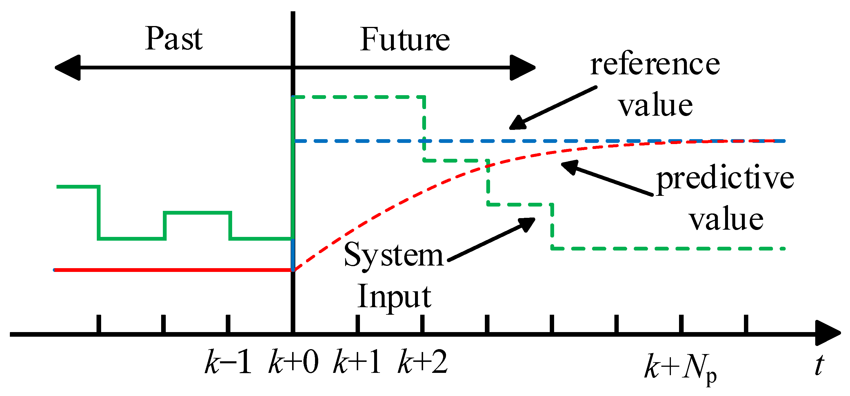
The range of applications for LIM servo systems is growing, and with it, so are the low- and medium-speed performance requirements of modern servo systems. Examples of these applications include wave energy power generation, CNC machine tools, urban rail transit, electromagnetic catapults, aerospace, and other fields. These applications demand good characteristics and anti-jamming performance—that is, the ability of the motor to run smoothly under specific load and speed changes while responding swiftly to changes in the commanded value. To control the motor, the MPC takes a multi-step technique. MPC has many benefits, including a good control effect, high accuracy, strong robustness, and low requirements for model accuracy. Its application in LIM servo systems is highly promising because it uses control strategies like multi-step prediction, feedback correction, and rolling optimization.
Finite control set model predictive current control (FCS-MPCC), finite control set model predictive torque control (FCS-MPTC), finite control set model predictive chain control (FCS-MPFC), and finite control set model predictive speed control (FCS-MPSC) are the four general categories into which finite control set model predictive current control (FCS-MPC) can be divided based on the control objective. The cost function primarily represents their differences: in FCS-MPCC, the control objective is current, and the evaluation index is current error; in FCS-MPTC, the control objective is torque, and the evaluation index is torque error; in FCS-MPFC, the control objective is magnetic chain, and the evaluation index is magnetic chain error; and in FCS-MPSC, the control objective is speed, and the evaluation index is speed error. In order to solve the problems of large overshoot and poor disturbance resistance under PI control, fast response speeds, little steady-state error, and nearly no overshoot are among the benefits of the fully predictive cascade speed and current control approach presented in [
9] with model predictive control for both the speed outer loop and the current inner loop. In [
10], a linear controller that suppresses the high-frequency current component and removes the steady-state error is included in a short prediction time domain predictive speed control approach that aims to achieve a quick reaction from the control system. Using the second-order Taylor series model of the quadratic cost function, the model predictive direct speed control (MPSC) approach proposed in [
11] is based on the Taylor series model and derives the fundamental voltage vectors with the same control period, improving the motor’s dynamic and static control performance. Using a reference voltage vector to construct a cost function, the weighting factor selection problem is resolved in [
12] by proposing a predictive direct speed control method without weighting factors. Additionally, an extended sliding mode load torque observer was designed to increase the motor’s robustness.
Furthermore, in order to improve the speed and current regulation performance under PI control, ref [
13] suggests using a model predictive current control technique that eliminates the nonlinear coupling of the d- and q-axis currents in surface-mounted permanent magnet synchronous motors using the control rate to feedforward and feedback control the current. In undertaking this, the decoupling effect is enhanced, and its dynamic performance is also enhanced. In [
14], a speed prediction current decoupling control for permanent magnet synchronous motors is proposed. This control improves the dynamic response performance of the control system by introducing model predictive control into the speed loop control and making use of its rolling optimization and feedback correction characteristics.
While the traditional FCS-MPSC removes the double-closed-loop structure by combining the speed and current in the cost function, it still has two major urgent issues with its single-loop structure that impede the motor’s dynamic response performance. First, there is a greater current and torque pulsation because the motor’s electrical time constant is smaller than its mechanical time constant, causing the current to fluctuate considerably faster than the speed. Second, the control period for both the speed and current must be the same since they are both contained in the cost function; nevertheless, in high-frequency speed measurements, the encoder produces some inaccuracies.
This means that even while the double-closed-loop structure of the traditional FCS-MPSC has worse dynamic performance than the single-loop structure, there are still some issues. Additionally, keep in mind that PI controllers—which are less resistant to changes in motor parameters because they are harder to update and have fixed values for PI parameters—are used for the majority of speed loop controls in the double closed-loop structure.
Thus, a double-closed-loop model-predictive control method is proposed for LIM in this paper to achieve the smooth control of LIM speed and prevent the issue of its speed being prone to overshooting and oscillation under PI control. This method constitutes a structure combining MPSC and the model predictive current control (MPCC), which improves the dynamic and disturbance-resistant performance of the motor and is nearly free of overshooting.
2. Mathematical Modeling of Linear Induction Motors
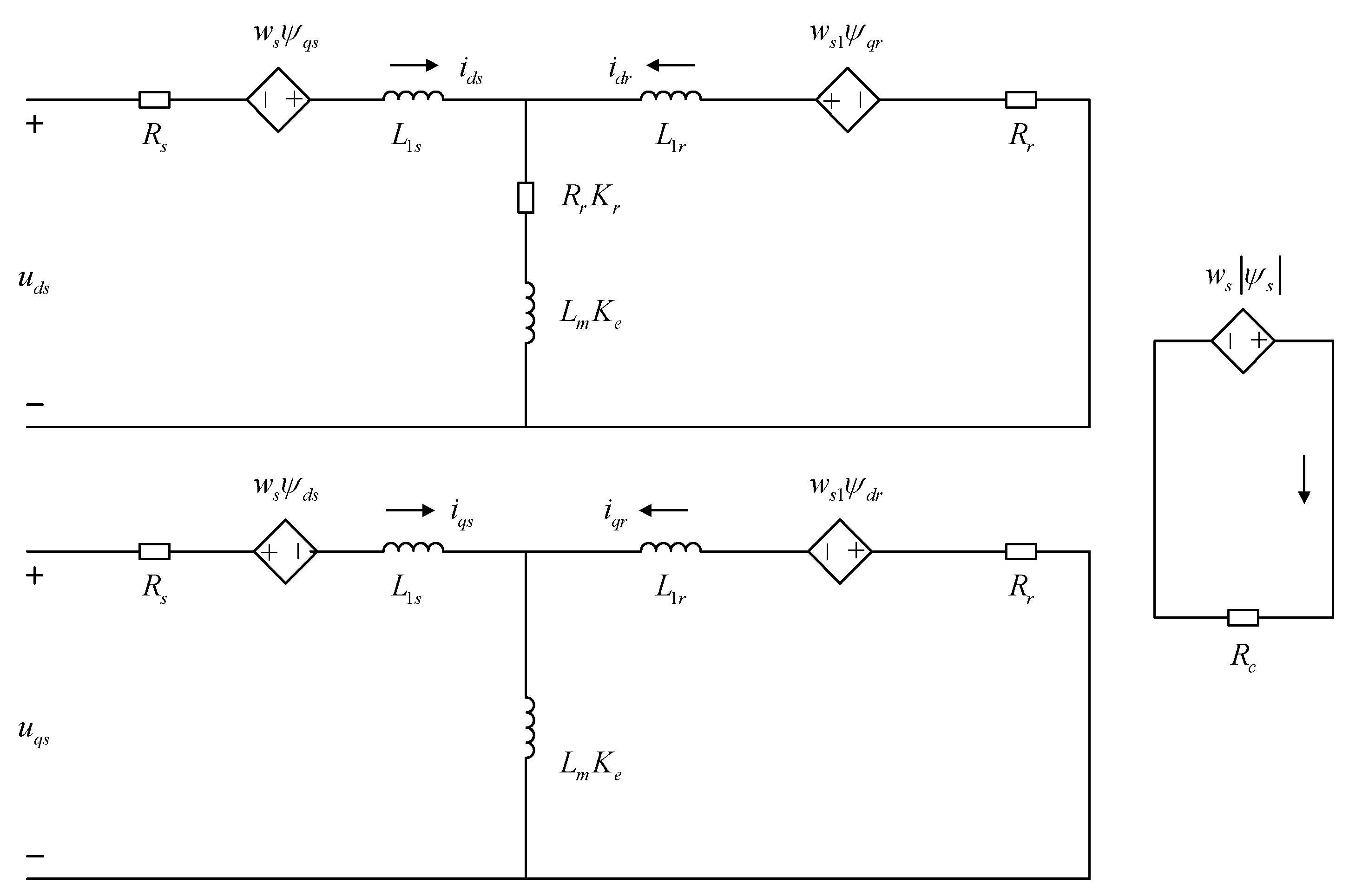
Generally speaking, after correcting the pertinent motor parameters and taking into account the impact of dynamic side-end effects, the LIM equivalent circuit is derived from the traditional rotary induction motor equivalent circuit. The iron consumption brought on by the primary stage’s leakage inductance, however, cannot be disregarded in the computation of motor losses due to the linear induction motor’s huge air gap and primary leakage inductance. In addition, the iron consumption branch current is significantly lower than the extraction branch current, which can be independent of the iron consumption branch, and the secondary loss is much smaller than the primary loss, meaning that the secondary leakage inductance is frequently disregarded in the mathematical model. In light of this, the paper uses the dq-axis asymmetric equivalent circuit of an LIM with an independent iron dissipation branch, as seen in
Figure 1.
This is equivalent to shunting the excitation inductance by connecting an inductor in parallel with the LIM excitation circuit. The model starts with the Q coefficient of the Duncan model, and the secondary guide plate eddy current generates a magnetic field that partially offsets the motor air gap magnetic field. Ke and Kr, which are the excitation inductance attenuation coefficient and secondary eddy current loss coefficient, respectively, are derived in this manner; the specific expressions are provided in the Appendix for Equations (A1)–(A3).
Consequently, the following is an appropriate way to write the asymmetric equivalent circuit voltage and flux equations of the LIM:
The thrust equation based on secondary flux orientation can be written as follows:
where
p is the differential operator,
β =
π/
τ. To simplify the expression below, let
Lme =
LmKe,
Rre =
RrKr.
The mechanical equations of motion are as follows:
where
F,
Fl,
B, and
m are the electromagnetic thrust, load, system viscosity coefficient, and traction weight of the linear induction motor, respectively.
4. Simulation and Analysis
The research object of this paper is a three-phase linear induction motor, the main parameters of which are shown in
Table A1 of the Appendix. The block diagram for the dual-closed-loop model predictive control system simulation of a linear induction motor is displayed in
Figure 6.
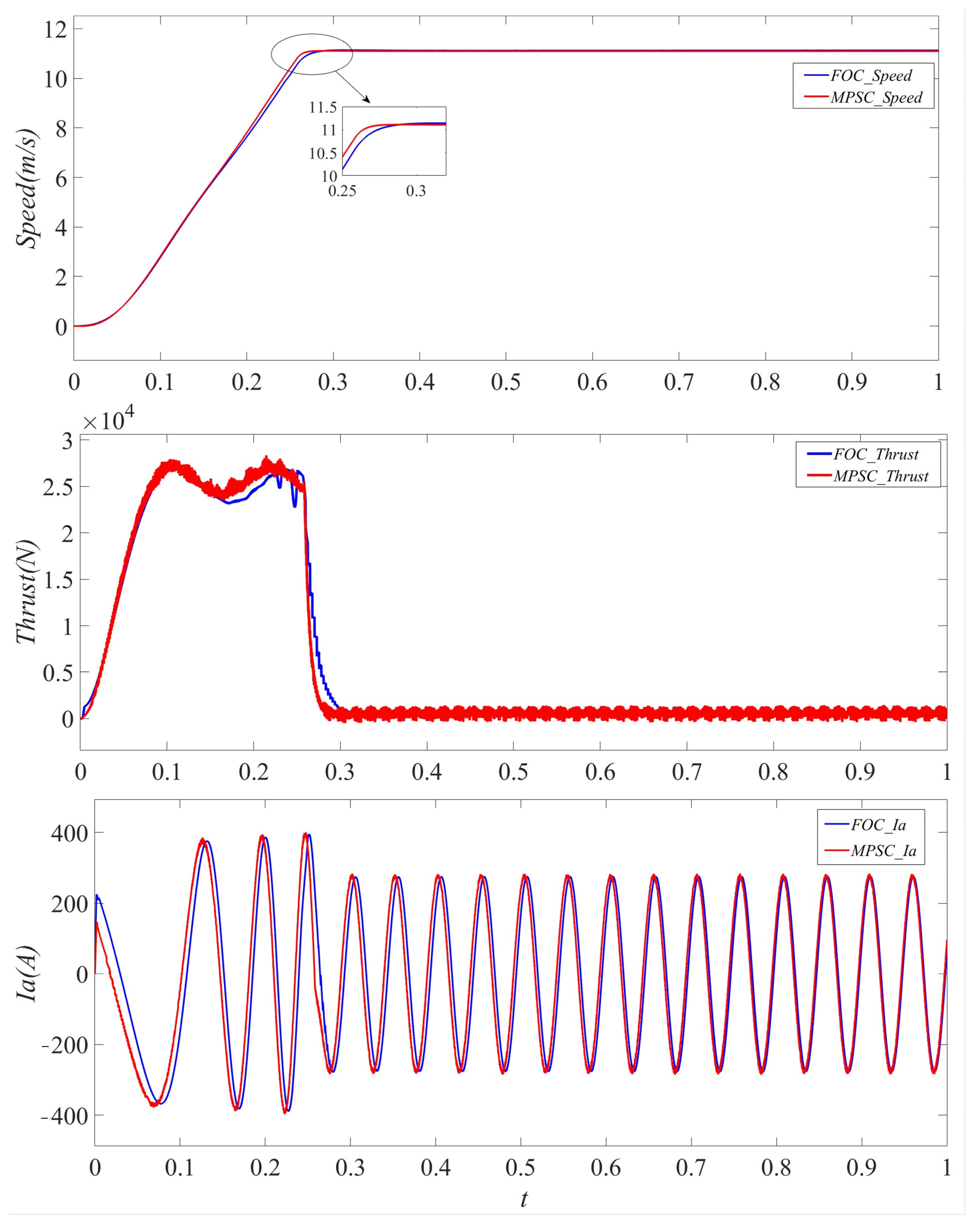
The simulated waveforms of the motor’s thrust, speed, and three-phase current under PI and MPSC + MPCC regulation at light-load starting are displayed in
Figure 7. The speed and load were set to 11.1 m/s and 600 N, respectively. The control approach suggested in this study has a faster speed response and nearly no overshoot when compared to the PI control, as demonstrated by the simulated waveforms.
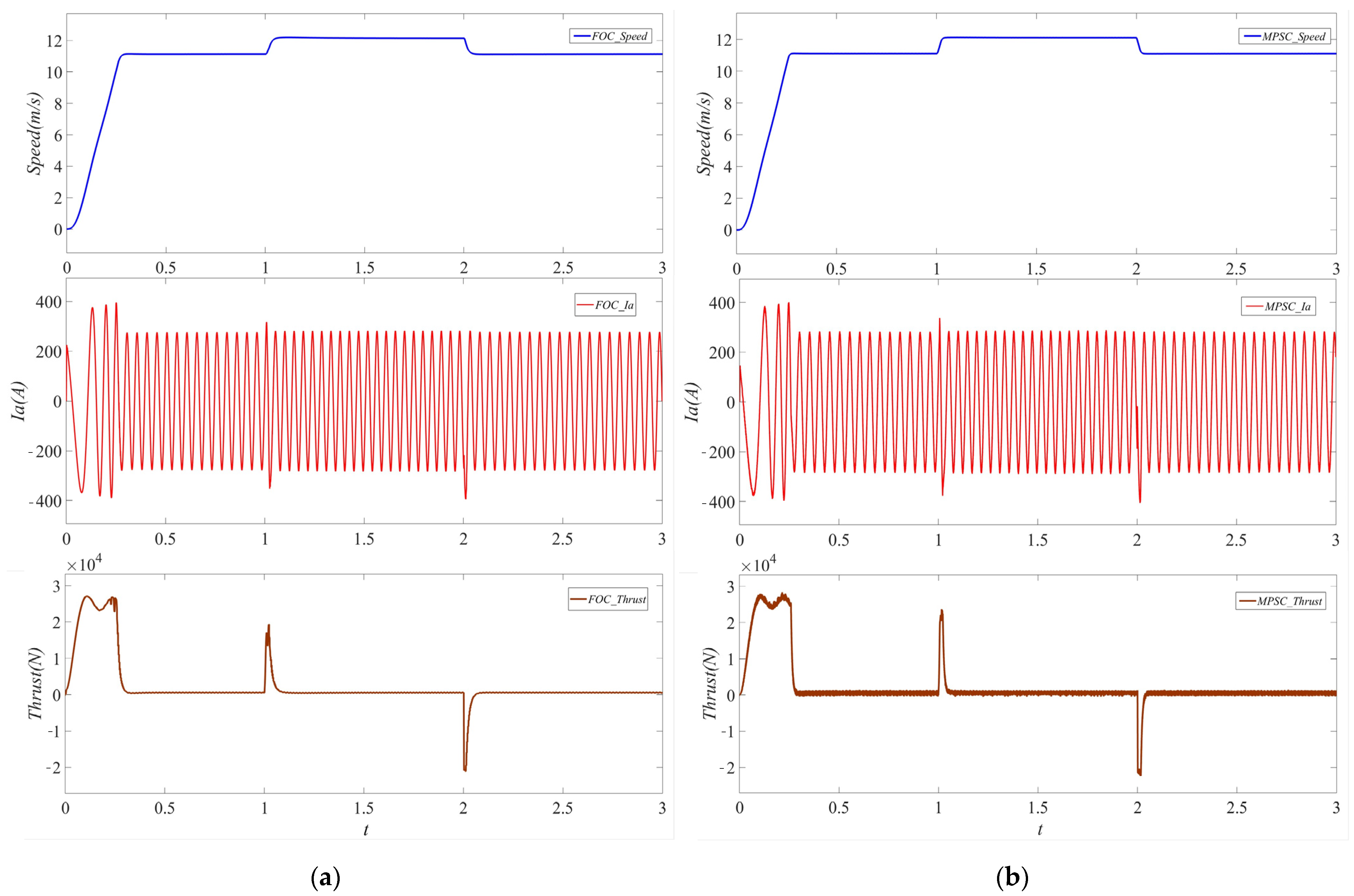
The motor is configured, as seen in
Figure 8, to abruptly accelerate to 12.1 m/s at 1 s and reduce to 11.1 m/s at 2 s. The simulated waveforms of thrust, A-phase current, and speed show that the MPSC + MPCC performs better at regulating speeds than the PI control.
The motor’s speed, thrust, and A-phase current response waveforms under the PI and MPSC + MPCC control when adding and removing the load are displayed in
Figure 9. The motor is programmed to increase the load to 5000 N in one second and decrease the load to 600 N in two seconds. The simulated waveforms clearly show that when adding or removing the load, MPSC + MPCC has superior anti-interference performance with reduced speed variation.
Table 1 and
Table 2 make it evident that the dual-closed-loop model predictive control suggested in this paper has a shorter acceleration and deceleration response time and a significantly better load-resistant capability than the traditional vector control, and its simulation results are in line with theory.
The dual-closed-loop model predictive controller suggested in this paper clearly improves results in suppressing overshooting, accelerating response speeds, and has anti-interference ability, as can be seen from the analysis of the aforementioned simulation results. This strong guarantee for the widespread use of linear induction motors is provided.


