Article

Numerical Simulation of Fishtail Biomimetic Groove for Dry Gas Seals

1
School of Petrochemical Engineering, Lanzhou University of Technology (LUT), Lanzhou 730050, China
2
State Key Laboratory of Tribology in Advanced Equipment, Department of Mechanical Engineering, Tsinghua University, Beijing 100084, China
*
Author to whom correspondence should be addressed.
Processes 2024, 12(7), 1494; https://doi.org/10.3390/pr12071494
Submission received: 18 June 2024 / Revised: 10 July 2024 / Accepted: 12 July 2024 / Published: 17 July 2024
(This article belongs to the Section Chemical Processes and Systems)

Abstract

:
In recent years, the use of dry gas seal technology in high-end industrial applications has become increasingly widespread. Existing research has primarily focused on unidirectional grooves. This study introduces an innovative approach by incorporating bidirectional grooves inspired by the biomimetic design of a carp tail, aiming to enhance sealing performance. The analysis of flow-field characteristics was conducted using Fluent software to evaluate the effect of different groove designs on sealing efficacy. The results indicate that curved grooves are more effective in directing gas flow and reducing fluid dynamic losses, thus improving the overall sealing efficiency. In particular, the outer-curved carp-tail groove exhibited superior dynamic pressure effects and reduced pressure drops across various operating conditions. The optimal radial dam-to-groove width ratio ranged from 3.8 to 4.1, and the optimal groove depth ranged from 6.5 to 9.6 μm. This investigation focused on the design and performance evaluation of biomimetic carp-tail grooves for dry gas seals, presenting a novel groove configuration for end-face sealing and further advancing the theoretical understanding of dry gas seals.

1. Introduction

Since the mid-20th century, extensive research and applications have focused on groove design in dry gas seal technology [1,2]. As science and technology have advanced, groove design has evolved from nascent exploration to mature implementation. Today, various groove types are increasingly being integrated into rotary equipment, demonstrating capabilities in enhancing operational efficiency and ensuring high reliability. Due to significant achievements in improving the sealing performance, the investigation and refinement of groove design have become central topics in mechanical seals [3,4,5]. Researchers are dedicated to further optimizing groove configurations to enhance the sealing efficacy and accommodate a wider range of operational conditions, laying the groundwork for future advancements in groove design.
Throughout the ongoing evolution of dry gas seal technology, numerous groove configurations have been instrumental in improving the sealing efficacy, reducing leakage, and extending equipment longevity. Representative scholars such as Hao and others [6,7,8,9] optimized the classical spiral groove, achieving ideal solutions for structural parameters such as groove width and dam length, and identified that specific shapes of spiral grooves help reduce the temperature of the flow field. Chen et al. [10,11] introduced two enhanced spiral grooves and examined the dynamic properties of gas films using finite element methods, refining the novel spiral-groove designs. Ibrahim et al. [12] investigated the effect of film thickness on the efficacy of spiral-groove dry gas seals and found that as the film thickness decreased, the opening force of the dry gas seal increased, while the temperature within the gas film rose. As spiral grooves are unidirectional, they only facilitate dry gas sealing in one rotational direction, leading many researchers to propose bidirectional sealing grooves. Notably, Wang [13,14,15,16,17] conducted flow-field calculations on bidirectional T-grooves, summarized the effect of structural parameters on sealing performance, and recommended an optimal range: a groove depth of 4–5 µm and circumferential ratio of 0.5. Additionally, Hu and Liu [18,19] proposed fir-tree type grooves and bidirectional dovetail grooves, where subsequent calculations revealed that both grooves had advantages over unidirectional grooves. Xu and Lin [20,21] explored the differences in gas film characteristics between traditional spiral grooves and T-grooves and resolved relevant sealing performance parameters using the finite difference method. They concluded that T-grooves were unsuitable for compressors a with unidirectional rotation. Moving beyond basic geometric groove designs, scholars have proposed several biomimetic grooves based on bionic knowledge. Inspired by bird-wing structures, Jiang Jinbo et al. [22,23] proposed a biomimetic micro-array spiral groove. They identified its optimal range through calculations, verifying that this groove design offers superior sealing performance compared with unidirectional spiral grooves. Sachs et al. [24] examined key parameters such as wing angle through modeling and computational fluid dynamics simulation of flying bird wings, presenting optimal design solutions for wing profiles. Sonya et al. [25] conducted a comprehensive assessment of biomimetic prototypes for mechanical seals including duck feet and fish fins, highlighting their significant practical value in enhancing seal performance. Among other things, MSM Saleh et al. [26] conducted numerical simulations to study the effects of rotating cylinders and porous layers on the forced convection of magnesium oxide-water and silicon dioxide-water nanofluids in a bifurcated groove channel (BGC). The results showed that the rotation direction of the cylinder significantly affected the formation of vortices within the channel, and the porous layers enhanced the heat transfer rates of the vertical and horizontal walls by 52% and 49%, respectively. Compared to SiO2, MgO nanoparticles increased the heat transfer rate by 2.6%. Li et al. [27] investigated the complex multiphase flow dynamics in the GDL of PEMFC and proposed a mesoscale multiphase coupling transport model based on the lattice Boltzmann method and the volume of fluid model. The results indicated that this method could capture the dynamic flow field within the fibrous porous media in detail. The study found that the surface wettability of the fibers influenced the distribution and stability of liquid water clusters, while fiber diameter played a key role in controlling lateral water diffusion and removal efficiency. Li et al. [28] proposed a multi-field coupled vibration modeling and solving strategy to study the transition modes of multiphase sediment vortex-induced vibrations (MSVIV). By employing the volume of fluid and level set methods with a volume correction strategy, they established a fluid-solid-acoustic dynamics model to explore the multiphase vortex transport laws. The residual theorem-based solving strategy was used to analyze the evolution behavior of MSVIV. The validation results were obtained through an MSVIV water model experimental platform with multi-channel sensing, and wavelet transform was used to process and obtain the abrupt energy characteristics. The study demonstrated that this strategy revealed the transition behavior of MSVIV, monitored the evolution process of MSVIV in real-time, and identified distortion characteristics.
The limitations of the current designs are primarily evident in the shortcomings of unidirectional grooves regarding dynamic pressure effects and fluid dynamic performance, making it challenging to meet the demands for efficient sealing in high-end industrial applications. Additionally, traditional designs tend to exhibit significant pressure drops and unstable sealing performance under varying operating conditions. To further enhance and refine the groove configuration of dry gas seals, a novel carp-tail groove has been conceived by embracing bionics principles and drawing inspiration from the carp-tail structure. The innovation of this design lies in the introduction of bidirectional curved grooves, which differs from traditional unidirectional groove designs, enabling more effective gas flow guidance and reduced fluid dynamic losses. The primary challenge of this study is in accurately simulating the fluid dynamic characteristics of the carp tail in the biomimetic design and verifying its practical effectiveness in dry gas seals through numerical simulations. By addressing these challenges, this study not only broadens the scope for the advancement and application of dry gas seal technology, but also enhances the performance and reliability of dry gas seal systems through pioneering design methodologies, providing theoretical foundations and technical support for further improving sealing technology in high-end industrial applications.

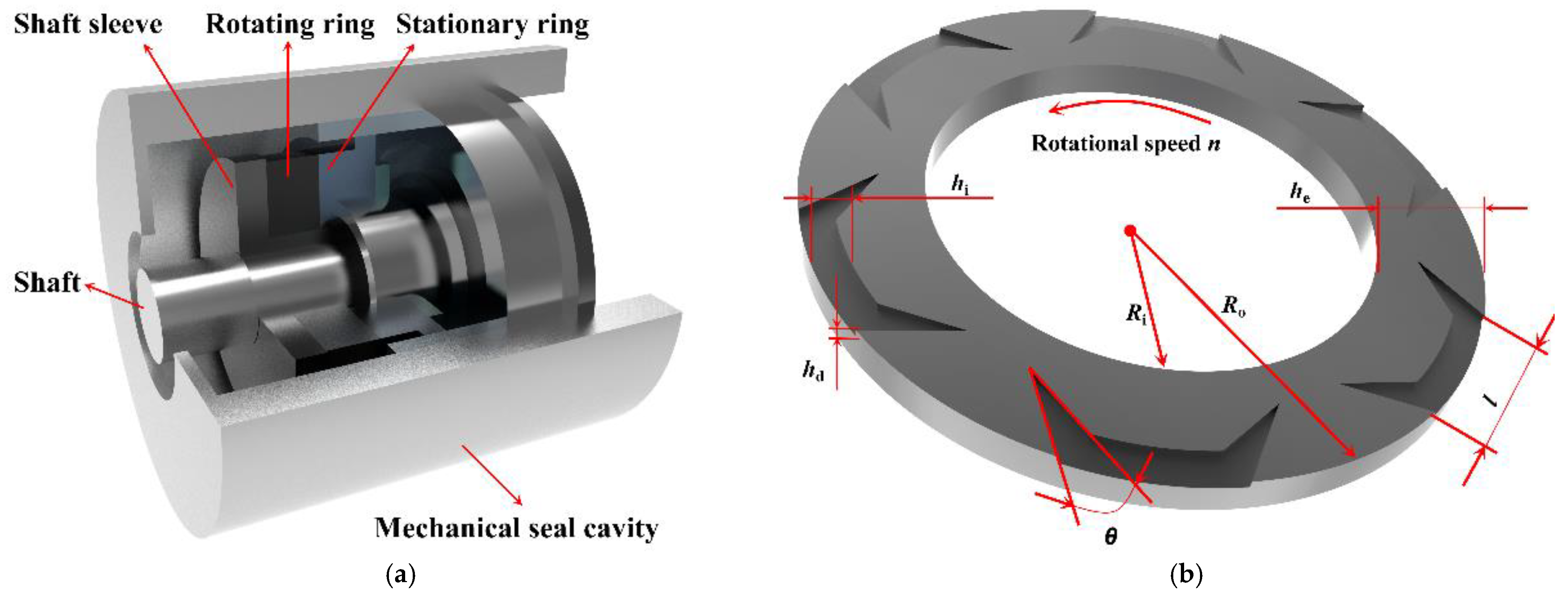
2. Computational Model

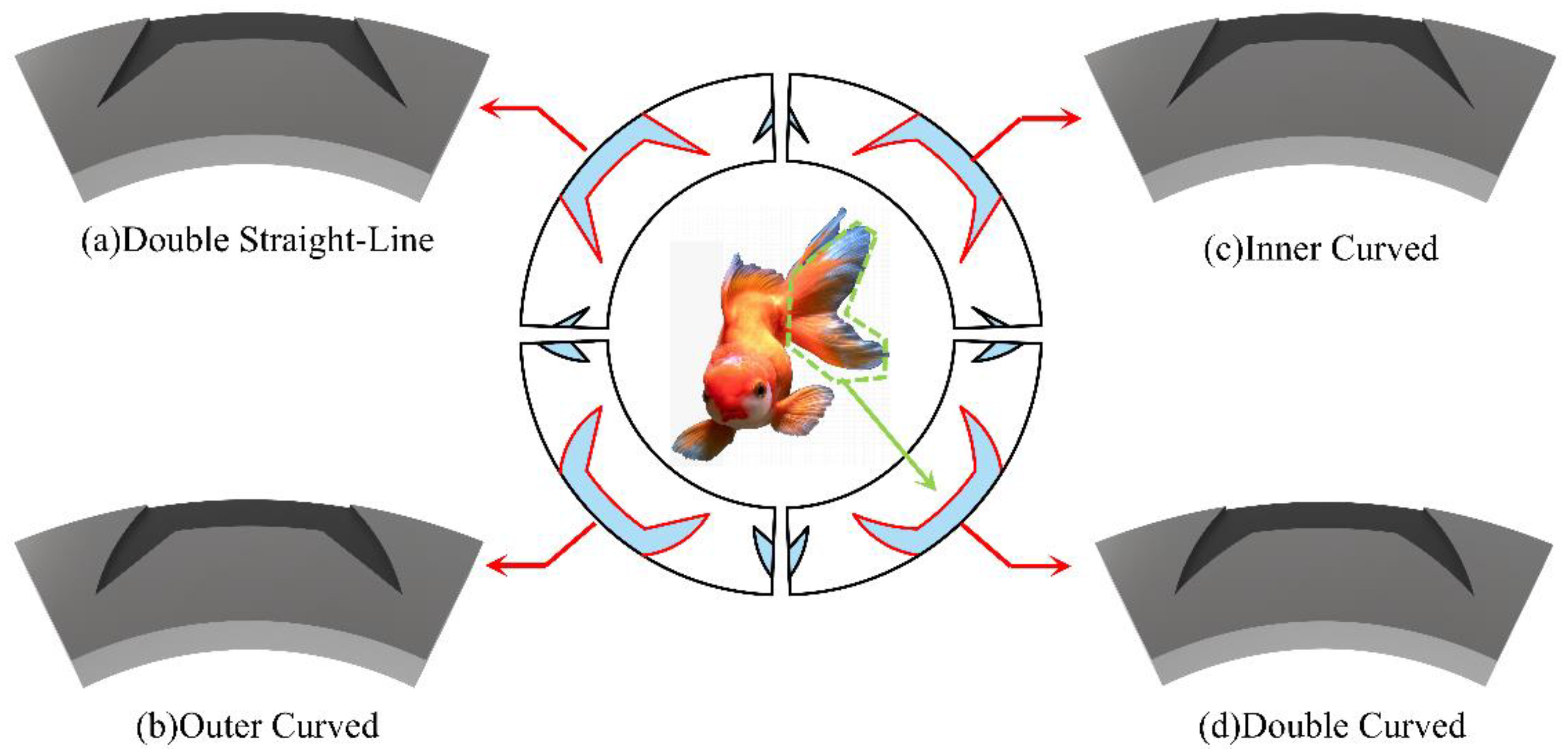
The Morphofunctionality of Fish Tails: A Key Role in Lubrication Flow

Over billions of years of biological evolution, fish have developed diverse tail structures that play crucial roles in dynamics. Taking the forked tail of the carp as an example, its design reduces turbulence and minimizes fluid resistance, which can similarly be applied to hydrodynamic lubrication flows. The forked tail optimizes the balance between thrust and drag by minimizing the water contact area. This biomimetic design approach can directly inform seal technology by optimizing groove designs to enhance fluid dynamic effects and reduce pressure loss, thereby improving the overall sealing performance. By analyzing and mimicking morphofunctional characteristics from nature, new perspectives and innovative solutions can be developed for hydrodynamic lubrication flow design. For instance, in seal groove design, biomimetic-curved grooves can effectively guide fluid flow, reducing dynamic losses and enhancing the reliability and lifespan of seals. Figure 1a is a schematic diagram of the sealing device, which includes the shaft as the central component of the device; the shaft sleeve wrapped around the shaft, providing a protective layer; the dynamic ring attached to the shaft and rotating with it; the static ring fixed within the sealing chamber and remains stationary; and the mechanical sealing chamber containing the dynamic and static rings, forming the sealing assembly. On the right side is a schematic diagram of the dynamic ring with carp-tail grooves that shows the relevant structural parameters.
Numerical simulations were performed using computational fluid dynamics software(ANSYS 2022) across a defined spectrum of operational conditions and parameters to investigate the sealing efficacy of the four distinct carp-tail groove variants. Figure 2 showcases the inspiration for the biomimetic design—the carp—located at the center of the image. Surrounding it are four circular diagrams, each depicting a two-dimensional schematic of a different carp-tail groove design, with the outermost diagrams illustrating the corresponding three-dimensional representations. These schematics highlight the structural designs and biomimetic origins of the various groove types. To elucidate the influence of groove structural parameters on seal performance, the radial dam area-width ratio was introduced as a metric to quantify the proportion of the dam area in the radial grooving of the carp-tail groove. The formula for calculating the radial dam area-width ratio Γ is:
Γ = h i h e
In the above-mentioned formula:
h e is the width of the grooved ring, mm;
h i is the width of the dam within the grooved ring, mm.
The structural parameters are provided in Table 1, while the operating condition parameters are detailed in Table 2.

3. Governing Equation and Calculation Equations

3.1. Basic Assumptions

This study was based on the principles of fluid dynamics and considered the structural attributes and operational parameters of end-face dry gas seal systems to conduct a computational assessment of the sealing efficacy of the novel groove designs. During the computation and analysis of the flow field, the following assumptions were made [29,30,31]:
  • The fluid is a uniform and consistently distributed medium.
  • There is no relative movement between the fluid and the sealing surface.
  • The influence of fluid volumetric forces and inertial forces is insignificant.
  • The sealing end-face is rigid and smooth.

3.2. Governing Equation

3.2.1. Continuity Equation

ρ t + ( ρ v x ) x + ( ρ v y ) y + ( ρ v z ) z = 0
In the above-mentioned calculation formula:
ρ is the density, kg/m3;
t is the time, s;
vx, vy, and vz are the velocity components in the x, y, and z directions, respectively, m/s.

3.2.2. Momentum Equation

( ρ v x ) t + ( ρ v x 2 ) x + ( ρ v y ) y + ( ρ v z ) z = p x + μ ( 2 v x x 2 + 2 v x y 2 + 2 v x z 2 ) + ρ f x ( ρ v y ) t + ( ρ v x v y ) x + ( ρ v y 2 ) y + ( ρ v y v z ) z = p y + μ ( 2 v y x 2 + 2 v y y 2 + 2 v y z 2 ) + ρ f y ( ρ v z ) t + ( ρ v x v z ) x + ( ρ v y v z ) y + ( ρ v z 2 ) z = p y + μ ( 2 v z x 2 + 2 v z y 2 + 2 v z z 2 ) + ρ f z
In the above-mentioned momentum equation:
ρ is the fluid density, kg/m3;
vx, vy, vz is the fluid velocity vector, m/s;
μ is the dynamic viscosity of the fluid, Pa·s;
p is the pressure of the fluid, N·m−2;
fx, fy, fz is the body force, N.

3.3. Sealing Performance Parameters

3.3.1. Opening Force F

In dry gas seals, “opening force” refers to the force required to overcome the initial tactile engagement or friction between the sealing interfaces when initiating the dry gas seal system. This force ensures the establishment of a stable gaseous film. The formula for calculating the opening force is as follows:
F = p d A
In the above-mentioned formula:
p is the pressure applied on the mesh during the calculation process, MPa;
A is the area of each mesh, m2.

3.3.2. Leakage Q

In dry gas seals, leakage is a crucial metric for performance evaluation. This parameter represents the volumetric amount of medium that passes through the sealing gap over a specified period. The formula for calculating leakage is as follows:
Q = p v d A ρ 0
In the above-mentioned formula:
v is the velocity vector, m/s;
A is the mesh area, m2;
ρj is the pressure, N;
ρ0 is the density of the fluid, kg/m³.

3.3.3. Film Stiffness K

The concept of film stiffness, K, was introduced to explain the stability of the gaseous film at the sealing interface. Film stiffness, K, is defined as the relationship between the restorative force generated by the gas film upon displacement and the extent of that displacement. The formula for calculating film stiffness is as follows:
K = F h c
In the above-mentioned formula:
F is the opening force of the gas film, N;
hc is the thickness of the film, m.

3.3.4. Stiffness-to-Leakage Ratio T

The stiffness-to-leakage ratio (SLR) was introduced to quantify how seal stiffness affects leakage. The formula for calculating the SLR is as follows:
T = K Q
In the above-mentioned formula:
K is the film stiffness, N/m;
Q is the leakage, kg/s.

4. Solution Approach and Domain

4.1. Three-Dimensional Model and Mesh Division

Figure 3a depicts the gaseous film of the double linear carp-tail groove formed by the gas passing through the gap between the seal interfaces. This gap is the focus of computation. Because the grooves are evenly distributed on the rotating ring, the flow-field characteristics within each groove are assumed to be identical. Thus, the flow attributes within a single groove can be analyzed using periodic boundary conditions to infer the flow-field dynamics of the entire sealing system [29,30].
Using the ICEM18.2 meshing software, nodal points, lines, and surfaces can be defined in the model, specifying distinct regions for boundary conditions.
(1) Rotating moving surface
v t o p = ω × r × e θ
Vtop is the rotating moving surface velocity vector;
ω is the angular velocity of rotation, rad/s;
r is the distance from the axis of rotation, mm;
eθ is the unit tangent vector.
(2) Quiescent surface
v b o t t o m = 0
vbottom is the velocity vector of the quiescent surface.
(3) Periodic boundary
φ ( r , θ 1 , z ) = φ ( r , θ 2 , z ) θ 1 = θ 2 + 2 π N
φ is a generalized variable;
N is the number of slots.
(4) Inlet
P = P i n
P is the pressure, MPa;
Pin is the inlet pressure, MPa.
(5) Outlet
P = P o u t
P is the pressure, MPa;
Pout is the outlet pressure, MPa.
To better capture the internal conditions of the flow field, the mesh was locally refined. These boundaries were set as periodic. The parameters relevant to the meshing process were then established, and the size and density of the mesh determined. The model was meshed, resulting in an structured grid. Figure 3a shows the schematic representation of the mesh. Figure 3b illustrates the results from a single-period calculation, whereas Figure 3c–f shows the schematic diagrams of the comprehensive period calculation outcomes obtained using periodic boundaries.

4.2. Boundary Condition Settings and Grid Independence Verification

To compute the flow fields, the three-dimensional double-precision solver in Fluent3D was used and configured for an ideal gas model. The fluid flow was assumed to be laminar, and pressure–velocity coupling was managed using the SIMPLEC method. Central differencing was employed for the diffusion terms, whereas second-order upwind discretization was used for the convection terms to enhance the accuracy of the results. The precision standard for iterative calculations was set to 10−4.
After establishing the setup, a grid independence verification process was conducted to ensure the stability and reliability of the computational results. This process identified an optimal mesh size that avoids unnecessary refinement, thereby preventing the wastage of computational resources and ensuring accurate results. Specifically, the grid independence verification tested twelve distinct mesh sizes using a model of the double-straight-line carp-tail groove, characterized by a film thickness of 10 μm and a groove depth of 3 μm. Operational conditions were set as follows: inlet pressure of 1.2 MPa, outlet pressure of 0.1 MPa, and rotational speed of 20 krpm. As shown in Figure 4, an increase in mesh count led to a noticeable rise in opening force. However, beyond approximately 700,000 mesh elements, further increases did not significantly affect the opening force results. This suggests that the model effectively captured the flow field characteristics at this density, ensuring the accuracy of results. Therefore, for this study, the model maintained a mesh count of approximately 700,000.

4.3. Verification of Model Correctness

The findings from the pertinent literature [13,32,33] were used to validate the accuracy of the flow-field calculations and simulations in this investigation. Two variables were selected for verification during the validation process: the opening force under varying inlet pressures and leakage at different groove depths. The inlet pressure ranged from 0.3 to 4.2 MPa, and the groove depth ranged from 3 to 7 μm. Other operating conditions included a rotational speed of 15,000 rpm, membrane thickness of 10 μm, and the medium within the flow field was air. As shown in Figure 5, the computed trends for the opening force and leakage in this study were consistent with those documented in the literature. An error analysis showed that the discrepancies between the results of this study and those in Reference [13] were relatively minimal, at just 4%. However, the discrepancies were more pronounced with References [31,32] at 23%. This divergence arose because Reference [13] also involved bidirectional grooves, whereas References [31,32] concerned unidirectional spiral grooves. The literature acknowledges a significant distinction in sealing performance between bidirectional and unidirectional spiral grooves, leading to larger discrepancies in the outcomes. Consequently, it can be deduced that the simulations in this study are precise and reliable.

4.4. Presentation of Calculation Results

Figure 6 and Figure 7 show the pressure distribution maps for the four distinct groove types under various operational and structural conditions. Figure 6 shows that the outer- and double-curved carp-tail grooves exhibited superior dynamic pressure effects compared with the other two designs. These grooves had less pronounced pressure drops and stable local high-pressure zones, indicating a lower sensitivity to changes in the operating conditions. This stability was attributed to the curved groove design, which more effectively channeled the gas flow, facilitating a stable and uniform flow velocity distribution. This arrangement helped minimize the effect of high-speed airflows and reduced the formation of high-pressure areas.
Figure 7 demonstrates that the double-straight-line and outer-curved carp-tail grooves effectively extended the high-pressure zones to the extremities of the grooves. The geometric configurations of the double- and outer-curved carp-tail grooves were conducive to directing gas flow toward the groove tips and positioning the local high-pressure areas at these points, thus achieving efficient dynamic pressure performance. Conversely, a local high-pressure area in the inner-curved carp-tail groove appeared in the central portion of the groove. This occurred because the inner curve causes the gas to disperse or rotate before reaching the groove tip, resulting in a high-pressure area in the midsection of the groove.
Further examination of the diagrams revealed that small high-pressure areas appeared on the reverse side of the low-pressure zones in the double-straight-line and outer-curved carp-tail grooves. This occurs because during operation, the direction of rotation influences the fluid dynamics, causing the fluid to move toward the high-pressure side and accumulate on the backside of the low-pressure area, creating localized high-pressure zones. The emergence of these high-pressure areas in low-pressure regions helps to balance the pressure disparities across the seal gap, mitigating the wedge effect, and potentially extending the seal’s lifespan. However, this phenomenon can also affect the stability of the sealing system, requiring a thorough consideration of its implications.

5. Results and Discussion

5.1. Effect of Operating Conditions on the Sealing Performance of Carp-Tail Grooves

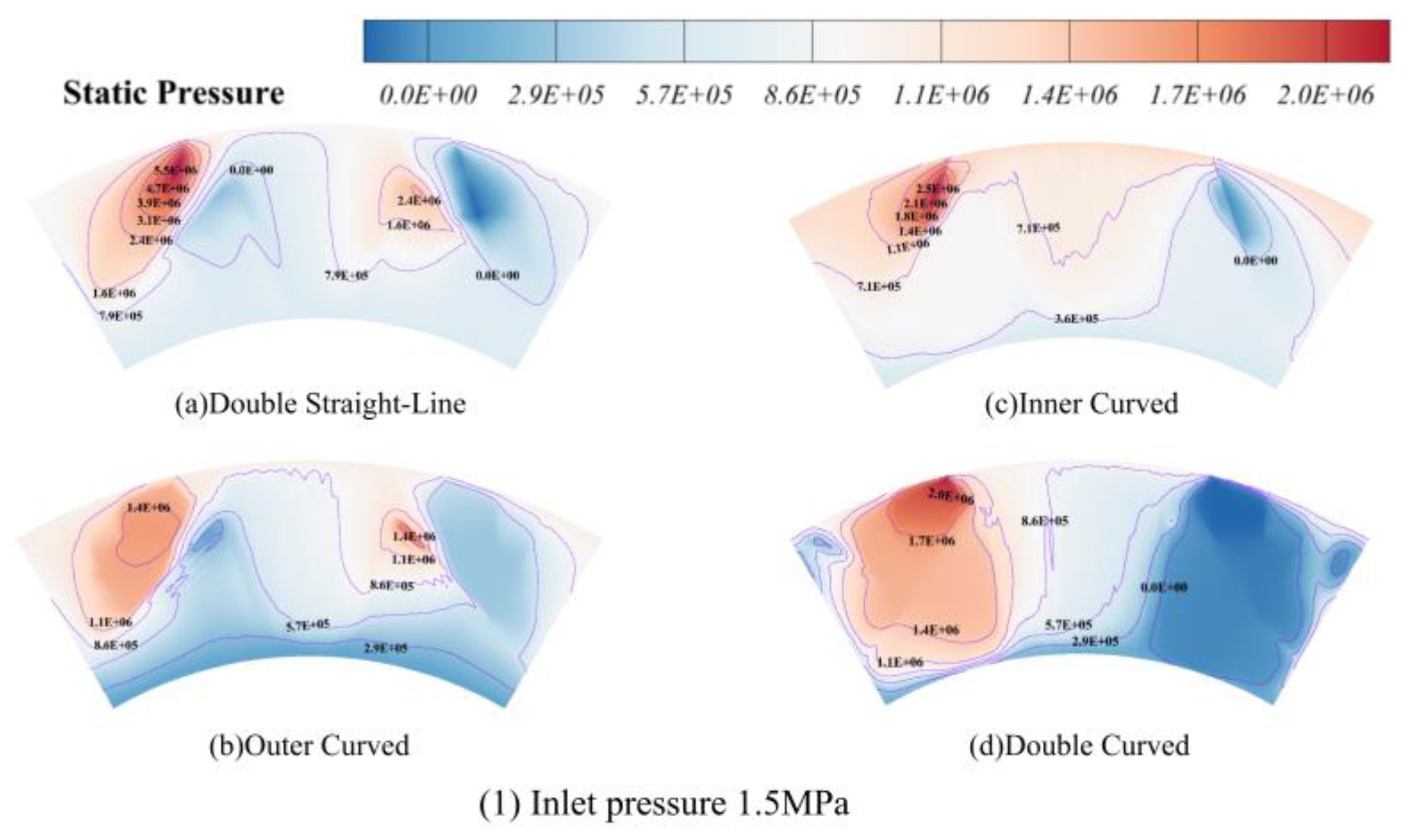
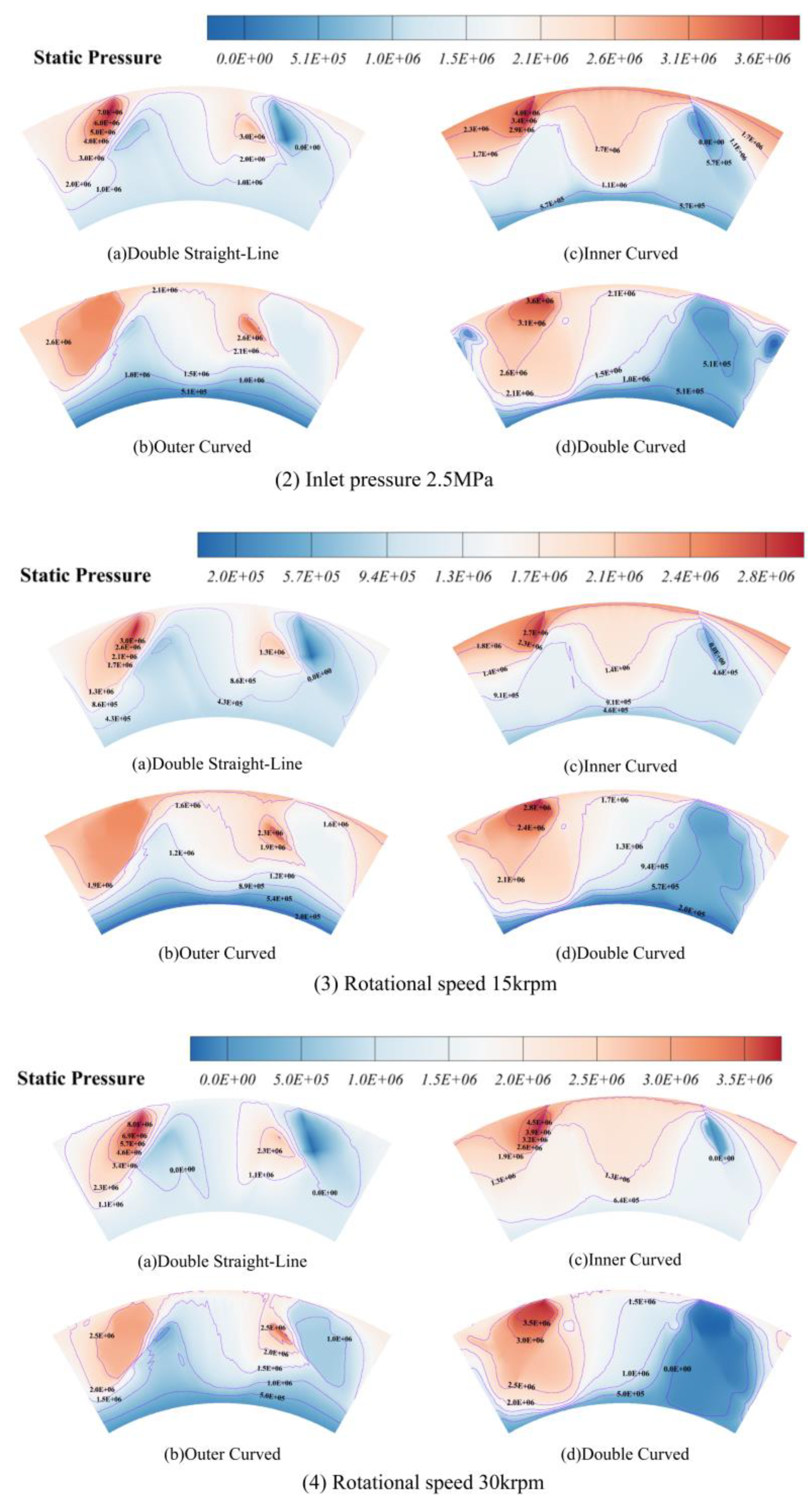
5.1.1. Effect of Inlet Pressure on the Sealing Performance of Carp-Tail Grooves

Figure 8a illustrates the variation in the opening forces of the four distinct carp-tail groove designs under varying inlet pressures. The graph revealed that the opening forces for all groove configurations were comparable at lower inlet pressures. An inlet pressure increase resulted in a proportional increase in the opening forces across all designs. Notably, the outer-curved carp-tail groove exhibited the most substantial increase, with its opening force at 4.5 MPa being 14.1 times greater than at 0.3 MPa. The disparity in the opening forces among the different groove configurations became significantly more pronounced with increasing inlet pressure. For example, at 0.3 MPa, the opening force of the outer-curved groove was 0.96 times that of the inner-curved groove, but at 4.5 MPa, it was 1.4 times greater. This can be attributed to the reduced internal gas pressure within the grooves at lower inlet pressures. Consequently, the force exerted by the gas pressure on the groove walls was minimal, and the influence of design variations on the opening force was relatively insignificant, resulting in similar forces across different designs. However, with increasing pressure, the streamlined design of the outer-curved carp-tail groove could more effectively reduce the fluid flow resistance, resulting in a greater increase in the opening force. In contrast, the inner-curved carp-tail groove design led to increased flow resistance, resulting in a smaller increase in opening force.
Figure 8b illustrates the leakage characteristics of the different carp-tail groove designs as the inlet pressure increased. As shown, the leakages for all groove configurations increased with increasing inlet pressure; however, the trends diverged among the various designs. Leakage of the double-straight-line carp-tail groove increased uniformly at first, and then rapidly as the inlet pressure rose. The leakage at an inlet pressure of 2.7 MPa increased by 166%. Although it subsequently decreased slightly, it still maintained an upward trend. The other three groove types exhibited a slow upward trend. The leakage of the double-straight-line carp-tail groove was significantly greater than that of the other three groove types, with its leakage at 4.7 MPa, which was approximately three times that of the other grooves. This phenomenon occurs because high inlet pressure causes fluid entry in the double-straight-line groove to be obstructed, leading to an increased pressure differential, resulting in a greater degree of opening of the leakage channel and causing a sharp increase in leakage. In contrast, the other three groove types have relatively stable structural designs, resulting in smaller leakage channels and relatively stable flow patterns, hence the slower increase in leakage.
Figure 8c illustrates that the trends in the film stiffness for different groove configurations under varying inlet pressures correlated with the trends in the opening forces, showing a uniform increase. However, as the inlet pressure rose, the disparities in film stiffness among the groove configurations became more pronounced. The outer-curved carp-tail groove demonstrated the highest stiffness at 4.17, whereas the inner-curved carp-tail groove exhibited the lowest at 3.1. These variations in the sealing performance can be attributed to the distinct pressure distributions and flow trajectories inherent to each groove design. For instance, due to its geometric attributes, the outer-curved carp-tail groove affords superior gas flow regulation, resulting in enhanced film stiffness under elevated pressures.
Figure 8d shows that the SLR of the outer-curved carp-tail groove experienced a rapid increase with rising inlet pressure, then began to decline, and eventually stabilized. The other three groove configurations exhibited different behaviors: the SLR of the double-straight-line carp-tail groove underwent a sharp decrease, a slight increase after reaching 3.3 MPa, and then stabilized; the inner-curved carp-tail groove’s SLR stabilized following a decline accompanied by a slight increase; the double-curved carp-tail groove’s SLR initially decreased, and then underwent a marked increase. Numerically, the discrepancies in SLR among different groove configurations were significant. With rising inlet pressure, the double-curved carp-tail groove demonstrated superior performance, whereas the double-straight-line carp-tail groove showed the poorest performance. The initial ascent followed by a descent in the SLR of the outer-curved groove occurred because, initially, as the inlet pressure increased, the rate of increase in the film stiffness exceeded the rate of leakage increase. However, as the inlet pressure continued to rise, the leakage rate surpassed the film stiffness increase rate, leading to a decline in the SLR.

5.1.2. Effect of Rotational Speed on Carp-Tail Groove Seal Performance

Figure 9a shows the fluctuation in the opening forces for different groove designs as a function of the changes in rotational velocity. It was observed that the opening force of the double-curved carp-tail groove consistently remained the highest among the four configurations, being notably higher than that of the others—2.2 times that of the alternative designs. The opening forces of the double- and inner-curved carp-tail grooves exhibited fluctuating trends with more pronounced fluctuations in the double-curved groove. The double-straight-line and outer-curved grooves displayed a progressively increasing and decreasing trend, respectively. These phenomena can be attributed to the double curvature of the double-curved groove, which creates vortices and turbulence within the flow field, resulting in fluctuations in opening force. As the rotational velocity increases, the gas film formed by the outer-curved carp-tail groove becomes more homogeneous, continuous, and stable, reducing the actual contact area between the fluid film and sealing surface, and marginally decreasing the opening force.
Figure 9b displays the leakage curves for different groove configurations as a function of the rotational velocity. The leakages for the double-straight-line and outer-curved carp-tail grooves decreased with increasing rotational velocity, with the double-straight-line showing a significant reduction of 23%, and the outer-curved groove was reduced by 7%. The leakage of the double-curved carp-tail groove fluctuated similarly to its opening force. The chart shows that the inner-curved groove had the smallest and most stable leakage, maintaining a constant rate of 7.5 × 10⁻⁶ kg/s. This was due to the increased centrifugal and compressive forces exerted on the fluid between the seal faces as the rotational velocity increased for the double-straight-line and outer-curved grooves. This compressive effect increased the fluid density and reduced the fluid volume and flow space, thereby decreasing leakage. Conversely, the double-curved carp-tail groove experienced fluid dynamic instabilities such as turbulence, resulting in erratic leakage and opening force fluctuations.
As shown in Figure 9c, influenced by the increasing rotational velocity, the film stiffness for all four groove configurations initially rose and then stabilized at 2.7 times the minimum observed value. It was evident from the chart that the film stiffness of the double-curved carp-tail groove consistently surpassed those of the other three configurations at higher rotational velocities. The effect of rotational velocity on the SLR is illustrated in Figure 9d, where all configurations initially showed an increase, followed by stabilization. However, the magnitude of this increase varied among the designs. The outer-curved carp-tail groove displayed the most prominent growth trend, with its SLR significantly exceeding those of the other three configurations. The SLR of the double-curved carp-tail groove was the least affected by rotational velocity, with an increase of only 9%, indicating minimal sensitivity to velocity changes. The changes in film stiffness can be explained as follows. With increasing rotational velocity, the fluid is pushed outward, increasing the air pressure within the seal gap, and enhancing the pressure stiffness of the film. Within a certain velocity range, the film stiffness increases with rotational velocity. Once a critical velocity is reached, the pressure distribution and the film stiffness stabilize. A higher rotational velocity leads to increased film stiffness, thicker films, and higher pressures in the seal gap, resulting in reduced leakages and higher SLR. The geometric shapes of the groove configurations also play a significant role: the smooth, continuous gas flow trajectory provided by the dual curvatures of the double-curved design reduces turbulence and energy loss, enhancing film stiffness. The outer-curved carp-tail groove improves the pressure distribution near the shaft, maintaining a higher film stiffness with lower leakage, thus maximizing the SLR.

5.2. Effect of Geometric Parameters on Carp-Tail Groove Seal Performance

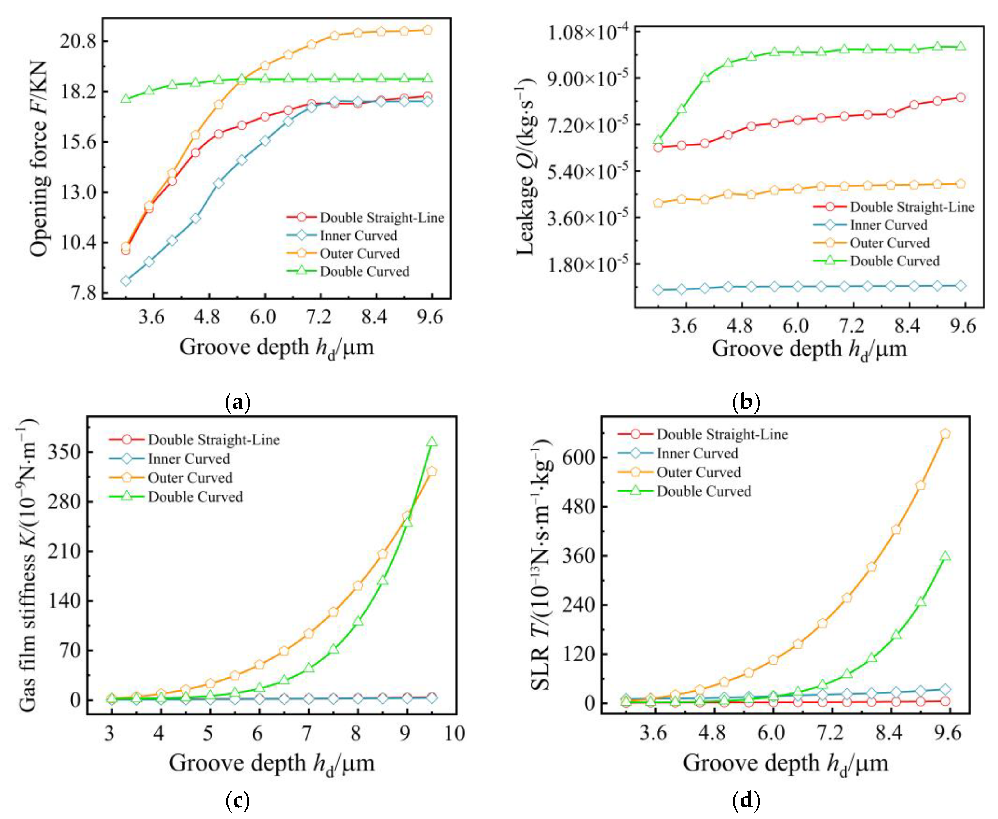
5.2.1. Influence of Groove Depth on Seal Performance

Figure 10 shows the effects of the groove depth on the seal performance of various groove configurations. Figure 10a shows how each configuration’s opening force varied with groove depth. The trends in the opening force differed among the configurations, with the double-straight-line, inner-curved, and outer-curved carp-tail grooves exhibiting an initial increase followed by stabilization. The double-curved carp-tail groove maintained a relatively stable trend, remaining at approximately 18 KN. Numerically, the outer-curved carp-tail groove displayed the highest stable opening force, approximately 21 KN. The changes in opening forces for the other configurations were more pronounced, with the inner- and outer-curved grooves reaching 2.1 times their minimum opening forces, and the double-straight-line groove was slightly less, at 1.84 times. Additionally, the opening forces of the double-straight-line and inner-curved grooves converged upon stabilization. This phenomenon occurs because, as the groove depth increases, the gas film formed within the groove is subject to greater confinement, leading to increased air pressure around the film, and consequently increasing the opening force with groove depth. As the groove depth increases, the gas flow in the groove stabilizes, and the surrounding air pressure distribution also stabilizes, leading to a steady-state opening force.
Figure 10b illustrates the leakage for the four groove configurations at various groove depths. The leakage of the double-curved carp-tail groove showed an initial increase followed by stabilization. In contrast, the leakage of the double-straight-line carp-tail groove progressively increased with increasing groove depth. The leakage for the outer- and inner-curved carp-tail grooves remained stable. Numerically, the double-curved carp-tail groove had the highest leakage, reaching 10.26 times that of the inner-curved groove; the increase for the double-straight-line groove was 33%, and for the double-curved groove, it was 55%. This is because the curved groove designs resulted in a more homogeneous fluid velocity and pressure distribution, reducing the propensity for leakage. The designs of the outer and inner-curved grooves effectively modulated the fluid flow while maintaining stable leakage rates. The leakage of the double-curved carp-tail groove was significantly higher than that of the other two curved grooves because its design induces complex flow patterns such as turbulence, which increases the leakage. In contrast, the simpler fluid flow patterns in the outer- and inner-curved grooves resulted in lower leakage. The trend of the double-curved groove first increasing and then stabilizing was due to the instability of the dynamic pressure effect with increasing groove depth. Once the groove depth reaches a certain value, the dynamic pressure effect stabilizes, and the leakage rate tends to stabilize.
As illustrated in Figure 10c, the film stiffness of the double- and outer-curved carp-tail grooves rapidly increased with increasing groove depth, and the rate of increase accelerated with deeper grooves. For example, the film stiffness of the double-curved carp-tail groove increased by only 7.88 when the groove depth was increased from 3 to 5.5 μm. However, as the depth further increased from 5.5 to 9.5 μm, the film stiffness surged by 353.62, an increase of 3700%. In contrast, the film stiffness of the double-straight-line and inner-curved carp-tail grooves remained stable. This phenomenon can be attributed to the deeper grooves enhancing the fluid dynamic effects, optimizing pressure distribution and increasing gas film thickness, thereby improving the load-bearing capacity and compression resistance. Additionally, the deep groove design amplifies the vortex effect of the gas flow, enhancing the dynamic pressure effect and stability of the gas film.
Figure 10d shows that the SLR trends for different groove configurations mirrored the trends observed in the film stiffness changes. The differences in sealing performance among the various groove configurations can be explained as follows. The double- and outer-curved carp-tail grooves, with their curved shapes, provide a smoother gas film distribution, enhancing the film’s overall stiffness. The slight increases in film stiffness observed in the double-straight-line and inner-curved carp-tail grooves are due to their linear segments offering less support compared to curved sections, resulting in a lower sensitivity of film stiffness to changes in groove depth.

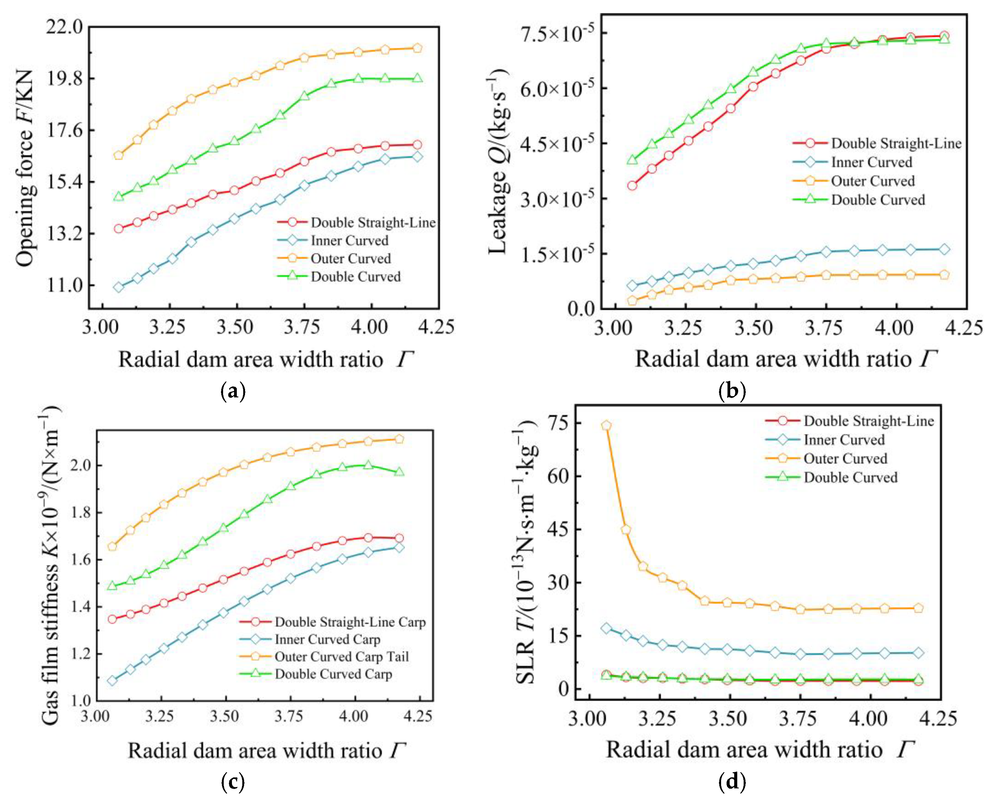
5.2.2. Effect of Radial Dam Area-Width Ratio on Seal Performance

Figure 11a illustrates the effect of changes in the radial dam area-width ratio on the opening force across different groove configurations. As the radial dam area-width ratio increased, all four groove types showed a rising opening force trend, with the increase rate slowing over time. The inner-curved carp-tail groove showed the most substantial increase, reaching 50.8%, whereas the double-straight-line carp-tail groove showed the smallest increase at 25%. The diagram indicates that the opening forces of the double-straight-line and inner-curved carp-tail grooves converged with an increase in the radial dam area-width ratio. The transition from a rapid to a more moderate increase in opening forces across all groove types was due to the enlargement of the radial dam–width ratio, which increased the effective cross-sectional area for fluid flow, thereby reducing the fluid velocity through the seal groove. This reduction in velocity increased the static pressure within the seal domain, increasing the contact pressure between the groove walls and the rotor, thus intensifying the opening force. As the radial dam area-width ratio continued to increase, the fluid velocity progressively stabilized, leading to a deceleration in the opening force rate and eventual stabilization.
Figure 11b shows the leakage curves with respect to changes in the radial dam area-width ratio. As the radial dam area-width ratio increased, the leakages for the double-straight-line and double-curved carp-tail grooves progressively rose and tended to converge, with their disparity from the other two groove configurations widening. At a radial dam-width ratio of 4.17, the leakage of the double-curved carp-tail groove was eight times that of the outer-curved carp-tail groove. The leakages for the outer- and inner-curved carp-tail grooves increased slowly with the rising radial dam area-width ratio and tended to stabilize, with an increase of only 80%. This increase was mainly due to the relative enlargement of the gap width compared to the seal diameter, providing a larger area for gas transit. Particularly, in the cases of the double-straight-line and double-curved carp-tail grooves, leakage markedly increased as the dam width ratio rose, and leakages of these two types tended to equalize. Conversely, the outer- and inner-curved carp-tail grooves exhibited more stable leakage increases, which was attributed to the effective flow regulation provided by their curvilinear configurations. Specifically, the outer-curved design facilitated superior fluid guidance and reduced the flow velocity, thereby diminishing leakage.
Figure 11c shows the gas film stiffness of different groove types for various radial dam width ratios. It was observed that the film stiffness for all four groove types increased to varying extents as the radial dam area-width ratio grew. The inner-curved carp-tail groove exhibited the most significant increase in film stiffness, reaching 52.1%, whereas the double-straight-line carp-tail groove showed the most modest increase at 25.5%. Trend analysis indicates that as the radial dam area-width ratio enlarged, the film stiffness stabilized and decreased slightly. For instance, the double-curved carp-tail groove achieved maximum film stiffness at a radial dam area-width ratio of 4.05, with further increases in the width ratio leading to a reduction in film stiffness.
Figure 11d demonstrates that the SLR for all groove configurations decreased with the amplification of the radial dam area-width ratio, stabilizing once the ratio reached 3.41. Additionally, the differences between the various groove configurations diminished as the radial dam area-width ratio increased. For example, at a radial dam area-width ratio of 3.06, the SLR of the outer-curved carp-tail groove was 20.1 times that of the double-straight-line carp-tail groove. However, this ratio decreased to 9.9 times when the radial dam area-width ratio expanded to 4.17. Moreover, the analysis showed that the double-straight-line and double-curved carp-tail grooves were less affected by increases in the radial dam area-width ratio, maintaining relatively consistent SLRs that were similar in value. The changes observed in the seal performance across the four groove configurations as the radial dam area-width ratio increased can be attributed to improvements in the fluidity of the gas within the seal groove, reducing the localized high-velocity airflow. However, excessively wide dam areas may cause the gas to linger too long within the groove, negatively affecting the sealing efficiency.

6. Conclusions

The results suggest that the configuration of the seal groove considerably influences the sealing performance. A marked enhancement in the seal performance was observed when the outer straight line of the groove was replaced with a streamlined curve. However, curving only the interior of the groove did not improve the performance. Therefore, groove designs with an external curved profile are more beneficial for seal groove selection.
There were considerable disparities in the sealing performance among the different groove types under various operating conditions. Under high-pressure conditions, the double-curved carp-tail groove significantly outperformed the other three types; under high-speed conditions, the outer-curved design distinctly excelled.
The recommended value for the radial dam width ratio is between 3.8 and 4.1. Under conditions requiring deep grooves, the sealing performance of the outer-curved carp-tail groove was significantly superior to those of the other three types. Therefore, the use of an outer-curved carp-tail groove is advocated in dry gas seals, where deep grooves are necessary.

Author Contributions

Conceptualization, B.C. (Bowen Cui); methodology, Xuexing Ding.; software, Shipeng Wang.; validation, Lanxia Zhang.; formal analysis, B.C. (Boyou Chen); investigation, B.W. (Baoyi Wu); resources, B.W. (Bo Wang). All authors have read and agreed to the published version of the manuscript.

Funding

This research received no external funding.

Data Availability Statement

Data for this study are not publicly available.

Conflicts of Interest

The authors declare no conflict of interest.

References

  1. Xu, H.; Yue, Y.; Song, P.; Mao, W.; Deng, Q.; Sun, X. Analysis on the dynamic characteristics of spiral groove dry gas seal based on the gas film adaptive adjustment model. Ind. Lubr. Tribol. 2023, 75, 406–414. [Google Scholar] [CrossRef]
  2. Peng, X.D.; Zong, B.; Jiang, J.B. Progress in dry gas seal performance evolution of unidirectional spiral groove and its derivative structures. CIESC J. 2017, 68, 1271–1281. [Google Scholar]
  3. Deng, Q.; Sun, X.; Xu, H.; Mao, W. Thermal characteristics of dry gas seal in startup process considering microscale effects. Lubricants 2023, 11, 503. [Google Scholar] [CrossRef]
  4. Faria, M.T.C. An Efficient finite element procedure for analysis of high-speed spiral groove gas face seals. J. Tribol. 2001, 123, 165–169. [Google Scholar] [CrossRef]
  5. Yuan, T.; Yang, R.; Li, Z.; Li, J.; Yuan, Q.; Song, L. Thermal characteristics and cooling effect for S-CO2 dry gas seal with multiple dynamic groove types. Appl. Therm. Eng. 2024, 236, 121896. [Google Scholar] [CrossRef]
  6. Shang, H.; Chen, Y.; Li, X.; Li, Y.; Wang, B.; Peng, X. Investigation of performance and parametric optimization of the typical spiral groove dry gas seal under transient disturbance operating condition. J. Braz. Soc. Mech. Sci. Eng. 2022, 44, 76. [Google Scholar] [CrossRef]
  7. Zhang, C.; Jiang, J.; Zhao, W.; Jin, J.; Peng, X. A comprehensive multi-objective, multi-parameter and multi-condition optimization of a spiral groove in dry gas seals. J. Braz. Soc. Mech. Sci. Eng. 2022, 44, 206. [Google Scholar] [CrossRef]
  8. Xu, Q.C.; Jing, J.B.; Chen, Y.; Peng, X.D.; Wang, Y.M. Numerical analysis of steady-state and dynamic characteristics of typical molded line groove dry gas seals. Tribology 2018, 38, 584–594. [Google Scholar]
  9. Chen, Y.; Jiang, J.; Peng, X. Dynamic characteristics and transient sealing performance analysis of hyperelliptic curve groove dry gas seals. Tribol. Int. 2017, 116, 217–228. [Google Scholar] [CrossRef]
  10. Peng, X.D.; Tan, L.L.; Li, J.Y.; Sheng, S.E.; Bai, S.X. Numerical analysis of dry gas face seals with spiral groove and inner annular groove. In Proceedings of the 2008 Second International Conference on Integration and Commercialization of Micro and Nanosystems, Clear Water Bay, Kowloon, Hong Kong, 3–5 June 2008; Volume 42940, pp. 73–77. [Google Scholar]
  11. Shahin, I.; Gadala, M.; Alqaradawi, M.; Badr, O. Three dimensional computational study for spiral dry gas seal with constant groove depth and different tapered grooves. Procedia Eng. 2013, 68, 205–212. [Google Scholar] [CrossRef]
  12. Wang, Y.; Sun, J.J.; Tao, K.; Ma, C.B.; Tu, Q.A. Numerical analysis of T-groove dry gas seal and groove optimization. Tribology 2014, 34, 420–427. [Google Scholar]
  13. Wang, Y.; Lu, L.; Zhang, H.; Lyu, S. A simulation analysis and experimental research on T groove end face seal under mid-and-low speed. Int. J. Precis. Eng. Manuf. 2017, 18, 537–543. [Google Scholar] [CrossRef]
  14. Wang, Y.; Sun, J.; Hu, Q.; Wang, D.; Zheng, X. Orientation effect of orderly roughness microstructure on spiral groove dry gas seal. Tribol. Int. 2018, 126, 97–105. [Google Scholar]
  15. Li, X.; Wang, K.; Du, B. The Structure optimization of t-slots dry gas seal faces. In Proceedings of the 2016 International Conference on Advanced Materials Science and Environmental Engineering, Chiang Mai, Thailand, 26–27 June 2016. [Google Scholar]
  16. Sun, J.; Liu, M.; Xu, Z.; Liao, T. Research on operating parameters of T-groove cylindrical gas film seal based on computational fluid dynamics. Adv. Compos. Lett. 2019, 28, 096369351986437. [Google Scholar] [CrossRef]
  17. Hu, Q.; Zhu, J.M.; Wang, Y.; Tang, X.K.; Xu, W.C.; Zheng, X.Q. Performance analysis of fir tree-groove dry gas seal with radial orderly micro-structure. Adv. Eng. Sci. 2020, 52, 153–160. [Google Scholar]
  18. Liu, Z.X.; Zhou, Y. Numerical analysis of gas dynamic characteristics in bi-directional dry gas seal. J. Eng. Thermophys. 2013, 34, 1466–1469. [Google Scholar]
  19. Xu, W.; Tian, Y.; Song, Y.; Xu, Y. Bidirectional trapezoidal versus unidirectional spiral groove performance in dry gas seals. Int. J. Fluid Mach. Syst. 2021, 14, 220–228. [Google Scholar] [CrossRef]
  20. Gao, L. Steady simulation of T-groove and spiral groove dry gas seals. Int. J. Heat Technol. 2019, 37, 839–845. [Google Scholar] [CrossRef]
  21. Jiang, J.B.; Peng, X.D.; Bai, S.X.; Li, J.Y.; Chen, Y. Performance analysis and selection of a bionic birdwing multi-array spiral groove dry gas seal. Tribology 2015, 35, 274–281. [Google Scholar]
  22. Jiang, J.; Peng, X.; Li, J.; Chen, Y. A comparative study on the performance of typical types of bionic groove dry gas seal based on bird wing. J. Bionic Eng. 2016, 13, 324–334. [Google Scholar] [CrossRef]
  23. Sachs, G.; Moelyadi, M.A. CFD based determination of aerodynamic effects on birds with extremely large dihedral. J. Bionic Eng. 2010, 7, 95–101. [Google Scholar] [CrossRef]
  24. Quinn, S.; Gaughran, W. Bionics-an inspiration for intelligent manufacturing and engineering. Robot. Comput.-Integr. Manuf. 2010, 26, 616–621. [Google Scholar] [CrossRef]
  25. Wang, Y.; Ge, Y.; Huang, G.; Hu, Q.; Hu, P. Microscale flow field analysis and flow prediction model exploration of dry gas seal. IEEE Access 2020, 8, 52663–52675. [Google Scholar] [CrossRef]
  26. Saleh, M.S.M.; Mekroussi, S.; Kherris, S.; Boutera, Y.; Bouzaher, M.T.; Belghar, N.; Chamkha, A.J.; Kolsi, L. Effect of rotating cylinder on nanofluid heat transfer in a bifurcating grooved channel equipped with porous layers. Int. J. Mod. Phys. B 2023, 37, 2350289. [Google Scholar] [CrossRef]
  27. Li, Z.; Wang, C.; Li, L.; Wu, J.; Yin, Z.; Tan, D. Numerical investigation of mesoscale multiphase mass transport mechanism in fibrous porous media. Eng. Appl. Comput. Fluid Mech. 2024, 18, 2363246. [Google Scholar] [CrossRef]
  28. Li, L.; Xu, P.; Xu, W.; Lu, B.; Wang, C.; Tan, D. Multi-field coupling vibration patterns of the multiphase sink vortex and distortion recognition method. Mech. Syst. Signal Process. 2024, 219, 111624. [Google Scholar] [CrossRef]
  29. Xu, J.; Peng, X.; Bai, S.; Meng, X. CFD simulation of microscale flow field in spiral groove dry gas seal. In Proceedings of the 2012 IEEE/ASME International Conference on Mechatronics & Embedded Systems & Applications, Suzhou, China, 8–10 July 2012. [Google Scholar]
  30. Zhang, Z.; Ding, X.; Xu, J.; Jiang, H.; Li, N.; Si, J. A study on building and testing fractal model for predicting end face wear of Aeroengine’s floating ring seal. Wear 2023, 532, 205079. [Google Scholar] [CrossRef]
  31. Bublík, O.; Heidler, V.; Pecka, A.; Vimmr, J. Flow-field prediction in periodic domains using a convolution neural network with hypernetwork parametrization. Int. J. Appl. Mech. 2023, 15, 2350018. [Google Scholar] [CrossRef]
  32. Soukkary, T.E.; Straatman, A.G. The prediction of spatially periodic flows using a finite-volume model. Int. J. Numer. Methods Fluids 2003, 41, 303–317. [Google Scholar] [CrossRef]
  33. Zhang, H.; Huang, W.; Wang, Y.; Lu, L.; Lyu, S. Research on meshfree method for analyzing seal behavior of a T-DGS. Int. J. Precis. Eng. Manuf. 2017, 18, 529–536. [Google Scholar] [CrossRef]
Figure 1. Carp-tail groove. (a) Schematic diagram of dry gas seal device. (b) 3D diagram of grooved rotating ring.
Processes 12 01494 g001
Figure 2. Geometric model of a slotted-end face.
Processes 12 01494 g002
Figure 3. Diagram of the sealing gas film.
Processes 12 01494 g003
Figure 4. Sealing performance curve under different grid numbers.
Processes 12 01494 g004
Figure 5. Verification of result accuracy [13,32,33]. (a) Verification of opening force accuracy. (b) Leakage quantity accuracy verification.
Processes 12 01494 g005
Figure 6. Four trough pressure contours under different working conditions.
Processes 12 01494 g006aProcesses 12 01494 g006b
Figure 7. Pressure contour map of the outer-curved carp-tail groove with different parameters.
Processes 12 01494 g007aProcesses 12 01494 g007b
Figure 8. Effect of inlet pressure on dry gas seal performance across different groove types. (a) Opening force for different groove types. (b) Leakages for different groove types. (c) Film stiffness for different groove types. (d) SLR for different groove types.
Processes 12 01494 g008
Figure 9. Effect of rotational speed on the performance of dry gas seals with various groove types. (a) Opening force for different groove types. (b) Leakages for different groove types. (c) Film stiffness for different groove types. (d) SLR for different groove types.
Processes 12 01494 g009
Figure 10. Effect of groove depth on dry gas seal performance across various groove types. (a) Opening force for different groove types. (b) Leakages for different groove types. (c) Film stiffness for different groove types. (d) SLR for different groove types.
Processes 12 01494 g010
Figure 11. Effect of groove depth on the dry gas seal performance of various groove types. (a) Opening force for different groove types. (b) Leakages for different groove types. (c) Film stiffness for different groove types. (d) SLR for different groove types.
Processes 12 01494 g011
Table 1. Structural parameters of an end-face flexible foil seal.
Geometric ParametersSymbolsValues
Seal ring inner diameterRi/mm60
Seal ring outer diameterRo/mm90
Number of groovesN6
Film thicknesshc/μm10
Groove depthhd/μm3–9.5
Groove sharp angleθ20.73
Opening widthl/mm40.84
Radial dam area width ratioΓ3.06–4.17
Table 2. Operation conditions of an end-face flexible foil seal.
Operating ConditionsSymbolsValues
Inlet pressureP/MPa0.3–4.2
Outlet pressurePo/MPa0.1
Rotational speedn/krpm5–44
Air densityρ/(kg/m3)1.225
Air dynamic viscosityμ/(Pa·s)1.789 × 10−5
Disclaimer/Publisher’s Note: The statements, opinions and data contained in all publications are solely those of the individual author(s) and contributor(s) and not of MDPI and/or the editor(s). MDPI and/or the editor(s) disclaim responsibility for any injury to people or property resulting from any ideas, methods, instructions or products referred to in the content.

