Article

Controlled Micro–Nano-Scale Droplet Generation via Spin Dewetting

by
Vinod Vanarse
1,
Bolleddu Ravi
2,
Srijita De
3,
Saurabh Dubey
3 and
Dipankar Bandyopadhyay
1,3,4,*
1
Department of Chemical Engineering, Indian Institute of Technology Guwahati, Guwahati 781039, Assam, India
2
Department of Pharmaceutical Engineering, B V Raju Institute of Technology, Vishnupur, Narsapur, Medak 502313, Telangana, India
3
Centre for Nanotechnology, Indian Institute of Technology Guwahati, Guwahati 781039, Assam, India
4
Jyoti and Bhupat Mehta School of Health Sciences and Technology, Indian Institute of Technology Guwahati, Guwahati 781039, Assam, India
*
Author to whom correspondence should be addressed.
Processes 2024, 12(8), 1562; https://doi.org/10.3390/pr12081562 (registering DOI)
Submission received: 31 May 2024 / Revised: 5 July 2024 / Accepted: 24 July 2024 / Published: 25 July 2024
(This article belongs to the Special Issue Chemical Engineering – Environment, Sustainability and the Future)

Abstract

:
A combined theoretical and experimental study is presented to investigate the interplay of forces in the spin-dewetting process in order to achieve enhanced control over droplet generation. In this regard, toluene–polystyrene (PS) film is spin dewetted on a solid substrate to generate an array of droplets. The underlying mechanisms of the spin dewetting of the films into the droplets are explained with the help of a theoretical model followed by a long-wave linear stability analysis (LWLSA). Stabilizing forces like solution viscosity and surface tension play essential roles. The study uncovers that the centripetal force stretches the film radially outward, before it becomes ultrathin and undergoes dewetting under the influence of van der Waals forces, while the surface tension force acts as a stabilizing influence. On the other hand, the viscous force kinetically stabilizes the system to expedite or delay drop formation on the substrate. An imbalance of these factors ultimately decides the droplet spacing, which leads to interesting morphologies such as singlet, doublet, triplet, and clusters of droplets at specific PS concentrations in the range 0.0001–0.0005%, with a ~10–14 nm average droplet height. The experimental data revealed that, at ~3000 rpm, PS (0.01–0.1%) results in critical droplet spacings of λmax~98–172 μm, leading to immediate dewetting and uniform droplet formation. Our theoretical predictions are in close agreement with the experimental results, validating the present model. The insights gained in this work provide a foundation by presenting a robust framework for controlled droplet generation by optimizing process parameters to achieve the desired droplet size, distribution, and uniformity. The findings have broad applications in material science, biomedical engineering, and related disciplines.

1. Introduction

The generation of ordered micro- and nano-scale droplets has become a focal point of scientific research, owing to their multifaceted applications across an array of engineering products and processes [1,2,3,4,5]. The domains range from biotechnology [6] and electronics to materials science and microfluidics [4,5], where precise control over droplet properties such as size [3], content [1], and morphology [5] is critical for creating materials with enhanced capabilities. Among the other droplet production processes, of late, spin dewetting [7] has emerged as a promising and versatile pathway for producing homogenous micro- and nano-polymer droplets [8]. This method comprises the controlled thinning and subsequent dewetting of a liquid film on a substrate with the help of the centripetal force generated during the rapid spinning of the substrate [9,10].
A number of recent reports have revealed the underlying physical mechanisms of spin dewetting with the help of experimental [7,11,12,13] and theoretical [12,14,15] investigations. These works summarize that spin-dewetting is driven by an interplay between centripetal, viscous, capillary, and inertial forces, which collectively dictate the thermodynamics and kinetics of the stretching of a droplet into a film on a rotating solid substrate, followed by the dewetting of the same [8]. Utilizing these forces as a handle to engineer controlled droplet generation can offer an appealing approach to generating advanced materials with catered characteristics and have the potential to fulfill application requirements. For example, during the spinning process, while the centripetal force stretches the film radially outward on a surface, the van der Waals forces help with dewetting the film when they are stretched to an ultrathin (<100 nm) thickness, and the surface tension force [13] acts as a stabilizing influence for the system. An imbalance of these forces eventually decides the length scale of the instability [16,17], which can be correlated to the spacing of the droplets formed after the completion of the spin-dewetting process. The film’s thinning rate during the spinning stage and the droplet formation during the dewetting stage are also influenced by factors such as the viscosity of the film. Further, the inertial forces originating during the high-speed spinning and the Coriolis force also influence the droplet’s location.
In this direction, over the years, the researchers have identified the arrangement of these forces through rigorous analyses [14], leading to a comprehensive understanding of the numerous factors that can be modified to attain precise control over the resulting droplets. The fine-tuning of the interplay of these forces controls critical outcomes by systematically changing factors such as interfacial tension, substrate–film adhesive properties, film viscosity, film thickness, and spinning speed [12,13]. This complex arrangement of forces is crucial in controlling not only the size and spacing of the droplets but also their arrangement into complex patterns—a capability that holds vast potential in diverse technological realms [17,18,19]. Moreover, other fascinating secondary structures before droplet generation, like threads or finger-like structures, have also been minimized or highlighted, as per the requirements [20,21]. The culmination of these research efforts has allowed researchers to engineer droplet arrays with remarkable precision [3], leading to the generation of monodisperse droplets suitable for drug delivery [5], micro-lens arrays, surface patterning [7], microelectronics [5], biomedical devices [22], and smart materials [23] applications. This mastery over droplet engineering is not confined to the microscale alone. Exploring nano-scale spin dewetting [24,25] has revealed new avenues for creating unprecedentedly precise submicron structures.
In alignment with these advancements [26,27], the primary goal of this work is to provide an elementary controlled generation of micro–nano-scale PS droplets via the spin dewetting mechanism [28], corroborated by a simple theoretical model, as shown in Figure 1. We aim to explore a comprehensive understanding of the intricate dynamics at play by delving into the fundamental principles that govern spin dewetting. Additionally, we examine factors that influence the initiation, growth, and final characteristics of droplets. A significant focus of this work lies in delineating the experimental methodologies that empower meticulous control over droplet dimensions, shapes, and distributions with the simple mathematical model. The relative motion between the substrate and the PS droplet brings in Coriolis force [14], which influences the trajectory and shape of the droplets, potentially resulting in differences in droplet size and distribution. The insights may be helpful for the practical implications of employing spin dewetting-generated polymer droplets in diverse applications, ranging from precision drug delivery to tailored surface functionalization and advanced micro-optics.
The present study provides a unique insight into the interplay between centripetal force and van der Waals forces, showcasing a new level of control over dewetting through the precise manipulation of spin speeds and PS concentrations. This control surpasses previous methods by enabling more uniform droplet formation and tailored droplet morphologies. We propose a simple and one-step recipe for a plethora of generated PS droplets, including interesting doublet, triplet, and clusters of droplets, which have diverse potential applications. These applications leverage the unique properties of the generated micro–nano-scale droplets, such as their uniformity, controlled size, and surface characteristics, to innovate and enhance performance in materials science, biomedical engineering, chemical engineering, electronics, photonics, environmental science, and sensor technology. On the other hand, a recent study by Cai et al. (2023) [29] achieved droplet generation experimentally but using complicated material modifications and process step utilization.

2. Experimental Section

2.1. Materials

The chemicals used for the experiment—PS (average Molecular Weight: 280,000) and sodium dodecyl sulfate (SDS)—were procured from Sigma-Aldrich, Bangalore, India. The acetone, ethanol, H2SO4, and H2O2 reagents were procured from Merck, Mumbai, India. All the AR-grade chemicals were used without any further processing during experiments. Single-sided polished silicon wafers were procured from N J International Corporation, Mumbai, India (<100> orientation, boron-doped P-type, 0.01–0.02 Ω cm resistivity). All the solution preparation and glassware cleaning were performed with Milli-Q grade water. Substrates were coated using a spin-coater (Apex, Kolkata, India, NXGP1NA02).

2.2. Characterization

All the morphological characterizations were performed using an atomic force microscopy (AFM, Bruker, Mumbai, India, Innova series) set-up. The microscopic characterization was performed with an optical microscope (Leica, Kolkata, India, DM 2500 upright microscope, with Polarized Optical Microscope (POM) mode) attached to the high-speed camera (Photron, San Diego, CA, USA, Fastcam Mini UX-100). Image analysis was performed using the open-source software ImageJ-1.49v to calculate droplet periodicity. The complete experimental set-up is shown in Figure 2, before and after assembly.

2.3. Methods

A single-sided polished silicon wafer was cut into 10   m m × 10   m m in length and width. They were then cleaned following a standard cleaning procedure [30,31]. After this step, the substrates were placed in piranha solution (3:1 H2SO4 and H2O2) and kept at 70 °C to remove all organic and inorganic contaminants. Substrates were then individually placed in DI water and finally used after drying with a nitrogen (99%) gas stream. The stock solution of PS–toluene (1 g/mL) was prepared. The substrate was kept at rest, and then the diluted solution drop (~0.0001–0.0003 v/v) with toluene was dispensed on the surface. Furthermore, the substrates were spin-coated at the optimized speed [32] of ~1500–3000 rpm, with an acceleration of 5 s for 2 min. All the possible experimental measurement and calculation uncertainties in the droplet size measurement (AFM and optical microscope), experimental parameters (spin speed and solution concentration), and computational measurements using LWLSA (MATHEMATICA–10.4) have been judiciously mitigated with appropriate error optimization actions to maintain the accuracy and repeatability.

3. Theoretical Problem Formulation

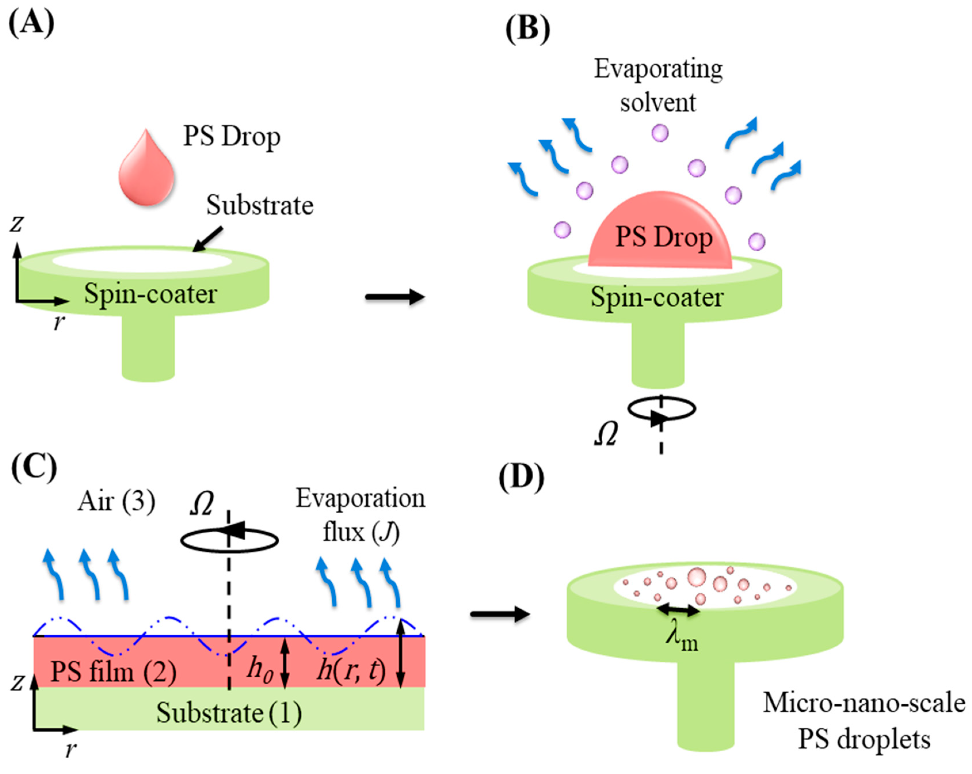
The reduction in thickness of the liquid film and the alteration in droplet spacing due to variations in spin speed, attributed to the omnipresent centripetal force, is elucidated using an extensive LWLSA. The cylindrical coordinate with the axisymmetric system is employed, where r and z are parallel and normal coordinates to the substrate, as shown in Figure 3. As the concentration of the PS in the toluene (volatile solvent) during spin-coating was very low during experiments, a Newtonian and incompressible fluid film is assumed [13], T = = μ ( u + u T ) . Accordingly, the equations of motion, ρ u = P + · T = , along with the mass conservation equation for the film, · u = 0 , describe the viscous film layer dynamics, as shown in Figure 1C. Here, T = ,   u v r , v θ , v z , μ ,   ρ ,   γ m n and P ( = p π ) denoted the stress tensor, velocity vector, viscosity, density, and interfacial tension at the m n   m n = 12 , 13 , 23 , 33 interface and the effective total pressure inside the film consisting of static pressure in the liquid and intermolecular forces triggered excess pressure, respectively. The over-dot represented the convective derivative, the bold variables were vectors, the over double-bars were the tensors, and the curly bracketed symbols denoted the vector components.
The film is assumed to be non-slipping and impermeable ( u = 0 ) through the substrate at z = 0 . At the film–air interface ( z = h r , t ) , normal n · p 0 I + T = a · n n · p I + T = · n = γ 32 κ and tangential n · T = a · τ n · T = · τ = 0 stress balances are used, along with the kinematic condition h / t + u · s h = v z enforced as boundary conditions. Here, subscript ‘a’ denotes the variables corresponding to the bounding fluid air, I is the identity tensor, t represents time, and s = I n n · is the surface gradient operator. The unit outward normal and tangential vectors are expressed as n = n r , n z = ( h / r , 1 ) / 1 + h / r 2 and τ = τ r , τ z = ( 1 , h / r ) / 1 + h / r 2 , respectively. The subscripts preceded with a comma represent the partial derivatives if otherwise mentioned, and the deforming free surface curvature is defined as κ = s · n . The variable h r , t is the film thickness, and the symbol h 0 denoted the corresponding mean thickness (Figure 3C). The excess pressure is defined as π = A e / 6 π h 3 . The disjoining pressure is expressed in terms of the effective Hamaker constant ( A e ) , which is obtained from the binary Hamaker constants (or spreading coefficient) as, A e = A 12 + A 33 A 13 A 23 = 12 π d 0 S 132 .

Non-Dimensional Evolution Equation and Stability Analysis

The thin film equation of the deforming viscous thin film was obtained under the lubrication approximation. We formalized this approximation by considering r z and defining a small parameter of ε 1 , which is directly related to the (small) wavenumber of the deformations. According to the lubrication approximation, r O ( 1 / ε ) and ( z ,   h ,   v r ) O ( 1 ) ; also, because of low-speed flow, t O ( 1 / ε ) . Within this framework, reduced r and z directional equations of motion are P / r ρ Ω 2 r = μ ( 2 v r / z 2 ) and P / z = 0 , respectively, and the incompressibility condition is v r / r + v r / r + v z / z = 0 . The symbol, Ω , denotes the angular velocity (spinning speed) of the spin coater, as shown in Figure 3B,C. To investigate the effects of angular velocity, we assumed the azimuthal velocity ( v θ ) is constant throughout the radial direction in the thin film as, v θ = Ω r [33].
The no-slip ( v r = 0 )   and impermeable v z = 0   boundary conditions are enforced at the substrate–film interface z = 0 , alongside reduced normal P p 0 A e / 6 π h 3 + γ 32 2 h / r 2 γ 32 / h = 0 [33,34] and tangential v r / z = 0 stress balance at the film–air interface z = h r , t in the long-wave limit. Here, p 0 is the ambient gas pressure. The curvature of the deforming surface in the long-wave limit at the film–air interface z = h r , t is obtained as follows: κ h = z n z / z z + n r / r h = 1 / h 2 h / r 2 [9]. Here, ‘pressure jump’ is balanced by both the disjoining pressure and capillarity. All the reduced governing equations and boundary conditions and the kinematic equation [35] are as follows: h / t + v r h / r + J = v z , where J is the evaporation term [33,34] used to solve the governing equations. Solving all these equations and boundary conditions gives the nonlinear partial differential equation (PDE) for the evolving free surface of the PS–toluene film, wherein the last term in the equation accounts for the evaporation [36] of the volatile solvent, as follows;
h t 1 3 μ r r r h 3 γ 2 h r 2 + ϕ r ρ ω 2 r + 1 r r r h 2 2 μ γ r = 0
In order to perform linear stability analysis in the long-wave regime, we linearized the long-wave normal stress balance and the evolution equation using the normal linear modes, as follows: h r , t = h 0 t + h ( r ) e ω t + i k r and P = P ¯ + P r e ω t + i k r , where the symbols ω and k represent the linear growth coefficient and the wave number of disturbance, respectively. The over-tilde symbols represented the perturbed variables. The variables are non-dimensionalized using H = h / h 0 , R = r / h 0 , a viscous time scale such as T = t / ( h 0 2 ρ / μ ) , and using normal mode in the form H = H 0 + H e ω T + i K R . We consider the drop diameter as h in the theoretical formulation of the model simplification. Furthermore, the non-dimensional dispersion relation is obtained from the perturbed state equations, as follows:
R e ω = H a / H 0 K 2 + β / H 0 + K 0 C a K 2 ( H 0 3 / C a ) K 4
where C a 1 = ( γ ρ h 0 / μ 2 ) ,   H a = A ρ / 2 π h 0 μ 2 ,   J = β H a / H 3 C a 1 H R R / H + K 0 are inverse capillary, Hamaker number, and evaporation flux [34], respectively. The essential condition for the system to be unstable (stable) is R e ω > 0   R e ω < 0 . The dominant growth coefficient ω m and the corresponding wavelength λ m = 2 π / C a 2 H a / 3 H 0 4 + 2 β / 3 H 0 3 H 0 + K 0 are obtained by finding the global maxima of ω and the corresponding wavelength ( λ m ) from the dispersion relations. All the above mathematical equations are solved and analyzed in the commercial symbolic package MATHEMATICA®.

4. Results and Discussion

4.1. Experimental Understandings

The spin-dewetting experiment was performed for two different states of spin-coater. In one case, a PS drop was cast on the substrate in a stationary state of spin-coater and another in a constantly rotating motion, as shown in Figure 1A,B. When the solution drop was dispensed on the substrate, the substrate gained a high speed, as did the drop. This rotation can create a centripetal force [13] that pushes the PS drop radially outward from the center of the substrate. This outward flow of PS is a fundamental aspect of the spin-coating process. The flow of the PS drop during spin coating can generate various fluid instabilities [13,37]. These instabilities [20,37] can result from the interplay between surface tension, viscosity, and the centripetal force acting on the drop. Patterns like swirls, vortices, and radial lines have been observed. These patterns are the results of the complex interplay between fluid dynamics and substrate rotation. The volatile toluene evaporated, further influencing the fluid flow patterns [35]. The cast PS drop goes through transformations from droplet to spreading to non-uniform film formation. Regions of low film thickness might have experienced changes in surface tension due to faster evaporation [35], which led to the pattern formation, finally resulting in droplet generation [35]. Some of the patterns in the case of droplets dispensed on the stationary stage of the spin-coater observed resemble the Coriolis effect [14] because they involve rotational motion.
However, these patterns are primarily a result of centripetal and fluid dynamic effects rather than the actual Coriolis force [11,13,14]. In the latter stage, the relative motion between the rotating substrate and the PS droplet and the resulting Coriolis force may have affected the trajectory and shape of the droplets, potentially leading to variations in droplet size and distribution. Column (i) of Figure 4 shows the formed thread or capillary-like structures for 0.01 % PS drop, wherein the spin coater was stationary at the beginning and then attained the constant speed of ~1500 rpm. These structures may be attributed to the combination of centripetal force, surface tension, and viscosity that can lead to thin threads or capillary-like structures [15] before disintegrating into an array of droplets. For 0.01 % PS drop, the critical average λ m a x ~ 98   μ m and 0.1 % PS concentration resulted in λ m a x ~ 172   μ m . After these critical values, there exists a shift in the droplet spacing, depicting the vital role of PS in deciding the droplet spacing.
These structures may be stable for a period but are eventually expected to break into smaller droplets due to the opposing forces. On the other hand, column (ii) of Figure 4 shows the generated droplets wherein drop casting has been carried out on the rotating substrate at a constant speed of 1500 rpm. In the latter case, as soon as the drop contacts the substrate, it experiences the centripetal force. This force results in the rapid spreading of the liquid outward. Due to the immediate exposure to the centripetal force, the PS drop spreads out quickly and may form thread-like structures almost immediately, as the time scale of this step is too short and does not allow the intermediate structures to appear. This rapid substrate rotation also induces vortical motion in the dispensed PS drop. This rotational motion contributed to the stretching and thinning of the liquid [38], potentially creating complex flow patterns [20]. However, the surface tension still played a role in this case by resisting the spreading of the drop. Still, the immediate impact of the centripetal force dominates the initial spreading behavior. As in the case of an initially stationary substrate, the system eventually reaches an equilibrium state where the opposing forces balance the liquid’s spreading. However, the equilibrium may be achieved more rapidly in the case of the initially rotating substrate, due to the immediate influence of the centripetal force. Figure 4G shows the average droplet spacing for a 0.01 % PS drop, indicating an increasing space between the generated droplets. This may be attributed to the delayed setting of centrifugal force over time. However, in another case, it immediately acts, resulting in reduced λ m a x , as shown in Figure 4H. Along with the centrifugal force, the Coriolis force also contributes to deciding the path followed by the generated droplets, giving them curved trajectories, as shown in column (ii) of Figure 4E,F.
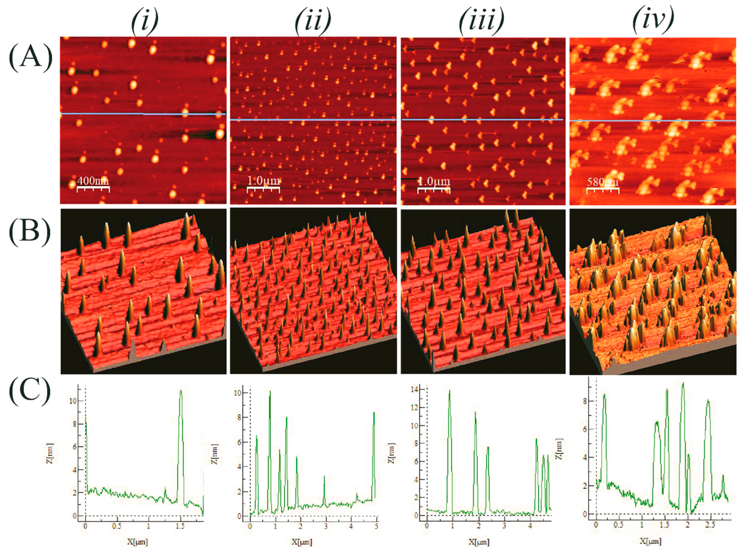
Figure 5 shows the AFM profiles of the spin dewetted PS droplets. Figure 5A shows the generated droplets from the PS drop, wherein A (iiv) are singlet, doublet, triplet, and clusters formed during the spin dewetting for 0.0005 % ,   0.0003 % ,   0.0003 % , and 0.0001 % PS, respectively, at 3000   r p m . The 3D profiles of the generated droplets on the substrate are provided in Figure 5B, which offers a better visualization of the formed droplets. The average height in Figure 5C(iiv) ranges from ~10 to 14 nm for respective images in the range of ~ 2   μ m × 2   μ m to ~ 5   μ m × 5   μ m surface areas. The generated droplets, in four different forms, have been observed near the substrate edge for different PS concentrations during experiments. Interestingly, we found doublet and triplet in the same PS concentration but at other locations as we moved away from the center of the substrate. This may be attributed to PS concentration, surface tension, viscosity, centrifugal force contributions, evaporation, or substrate surface property. Generated droplets were in continuous motion due to rotations. They continuously push away from the center, while newly generating droplets may follow a particular trajectory on which they hit previously formed drops. Due to the sudden obstruction and viscous resistance with evaporating solvent in the solution, they might have frozen on the way, taking a doublet shape and triplet near the substrate edge, where more droplets could have reached without losing the solvent.

4.2. Essential Understandings from Theoretical Modeling

The proposed theoretical model helps to gain insights into the underlying physics of the spin-dewetting process. The PS concentration in the solvent is very low during spin dewetting, allowing us to assume the Newtonian and incompressible film [38] of the solution for the modeling [38]. The formed thin, non-uniform film then disintegrates into droplets due to spin dewetting with associated forces in the system and due to solvent evaporating from the film [39]. We assume a uniform toluene-rich thin film on the substrate, which is influenced by the spin-coater’s rotational motion. Our central focus is on the film evolution dynamics during the process, irrespective of whether the PS drop is initially dispensed on a stationary or rotating substrate. We also assume that the spin coating and silicon wafer curvature influence the spreading of liquid PS [38]. The curvature creates a non-uniform radial distance from the center of rotation, impacting the centripetal force experienced by the liquid at different points on the wafer. This non-uniformity can lead to variations in the spreading pattern [39].
The rapid rotation and spreading of the liquid PS lead to the formation of threads or elongated structures. These threads are essentially assumed to be the result of a Rayleigh–Plateau instability on a rotating substrate [38]. The effects of the intermolecular force, capillary, and evaporation flux are incorporated into the model as the other possible causes of instability set in the system. The resulting dispersion relation from the LWLSA represents the combination of stabilizing and destabilizing forces that decide the final morphology of the film. The destabilizing (first two bracketed terms—Hamaker ( H a ) and evaporation ( β )) and stabilizing contributions (last term—inverse capillary ( C a )) are represented in Equation (2). However, droplets shrink upon drying, conducted in order to remove solvent traces present, if any, but their periodicity and shape remain unchanged [38]. Figure 6A–D shows the effect of H ,   H a ,   C a , and β variation captured through the obtained dispersion relation by solving ordinary differential equations (ODE’s). Figure 6A,B,D show the increased instability when increasing H ,   H a , and β , indicating their destabilizing contributions to the system and the stabilizing nature of Ca, as shown in Figure 6C. An increased evaporation rate of the volatile solvent triggers the droplet generation by contributing to system destabilization, resulting in a time and length scale increase, as shown in Figure 6D.
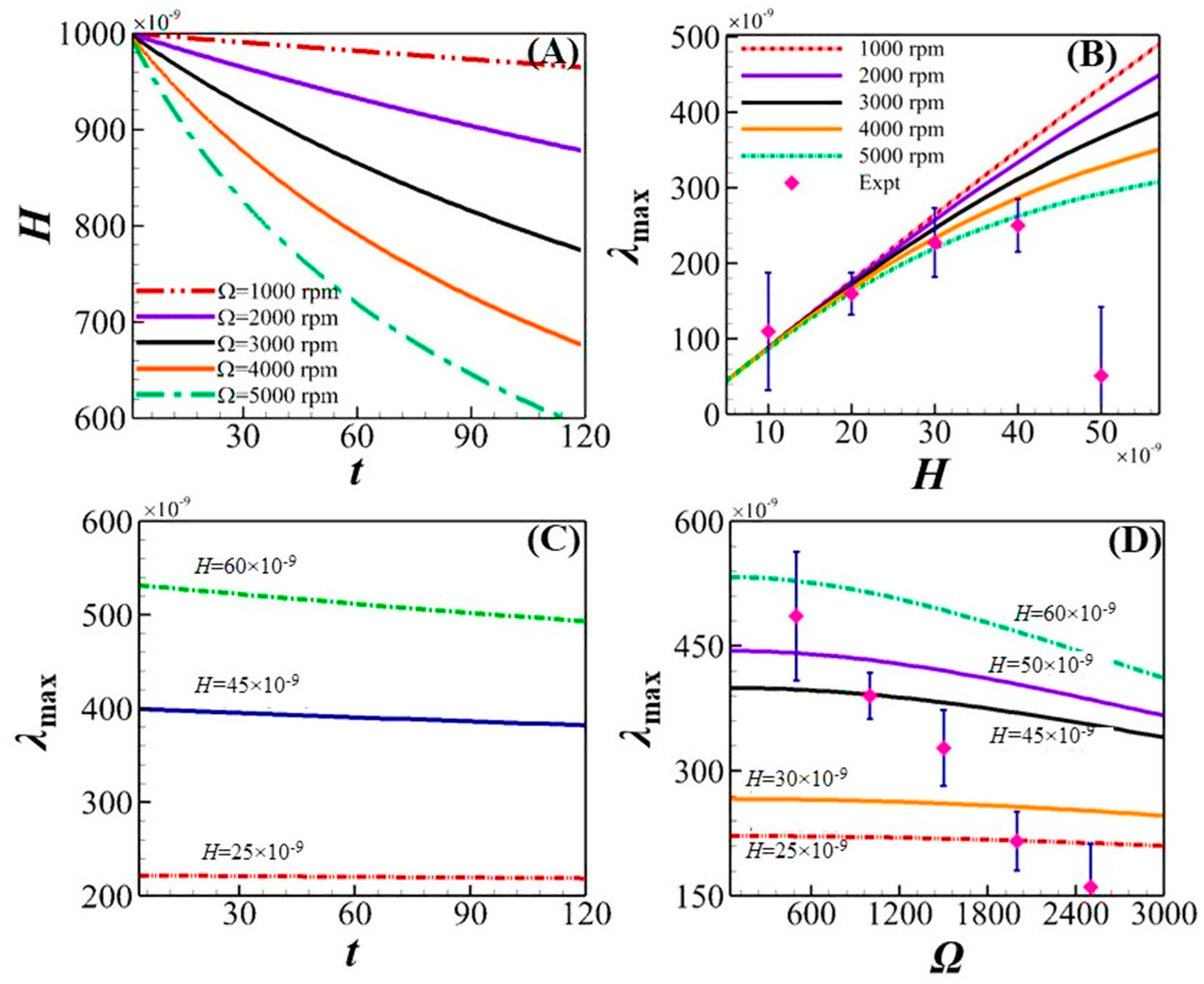
Figure 7A shows the variation in average film thickness, with t obtained from the thin film dispersion equation at varying spin speeds (Ω). The faster film thinning is attained due to the dominating centripetal force at high speeds, rapidly spreading the film. Figure 7B–D show the average droplet spacing ( λ m a x ) for varying Ω and H , respectively. Figure 7B compares   λ m a x obtained from theoretical model and experimental analysis for different Ω, and they agree well. The decreased droplet spacing with increasing thickness and spin speed may be attributed to the interplay between viscous force and surface tension, where the high viscosity of thick film offers more resistance to radially pushed droplets, and the capillary helps to minimize the surface area, leading to a reduced length scale. At lower film thickness, evaporation, along with other destabilizing forces, contributes to maintaining the high λ m a x that gives more droplet spacing initially, compared to high thicknesses. Figure 7C shows the variation in λ m a x with t at varying H , depicting the decreasing length scale at increased film thickness, which may be attributed solely to the kinematic parameter, viscosity. Figure 7D shows the comparison between experiments and theoretical analysis for λ m a x with Ω for H variation. The increasing Ω results in improved centripetal force in the system competing with the viscous force and surface tension. However, the combined effect of viscosity and surface tension’s stabilizing influence dominates the destabilizing influence of centrifugal force, giving a decreased length scale. The droplet sizes obtained experimentally were found to be in good agreement with the predictions from LWLSA using MATHEMATICA–10.4 software, with an overall uncertainty of ±10 nm. This consistency validates our model and demonstrates the reliability of our measurements.

5. Conclusions

A spin-dewetting study for PS (0.01–0.1%)–toluene solution is carried out in this work; using a spin-coater under stationary and rotating settings at the optimized speed of ~3000 rpm results in critical droplet spacings of λmax~98–172 μm. The development of intricate patterns is caused by centripetal force and the complex fluid dynamics at play, with volatile solvent evaporation impacting the process. Some patterns remind us of the Coriolis effect observed in the experiments. The AFM reveals the topographies of PS droplets that are altered by different conditions of the solution and the spin-coater, resulting in an average droplet height of ~10–14 nm at the lower concentrations of PS (0.0001–0.0005%). Interestingly, we observe four types of generated droplets at varying PS concentrations: singlet, doublet, triplet, and clusters of droplets. The theoretical modeling uses PS film thickness and intermolecular forces to explain film stability and the associated time and length scales of the instability using LWLSA. Higher spin speeds reduce the film thickness, resulting in early film dewetting. Theoretical and experimental droplet spacing assessments are in good agreement. The essential properties of the solution, such as viscosity, surface tension, and capillary effects, are crucial in deciding the length scale of the system.

Author Contributions

V.V., B.R. and S.D. (Saurabh Dubey) contributed to conceptualization; visualization; and methodology. Software; validation; formal analysis; investigation; data curation; writing—original draft preparation; writing—review and editing is done by V.V., S.D. (Srijita De)—visualization and formal analysis. The supervision; project administration; funding acquisition; resources and writing—review and editing were contributed by D.B. All authors have read and agreed to the published version of the manuscript.

Funding

We thank the Government of India for providing financial support through MeitY Grant no. 5(1)/2022-NANO and ICMR Grant no. 5/3/8/20/2019-ITR.

Data Availability Statement

The data supporting this study’s findings are available from the corresponding author upon reasonable request.

Acknowledgments

We thank Shirsendu Mitra, Pandit Deendayal Energy University-PDEU, Gandhinagar, Gujrat, India, for the productive discussions over the theoretical formulation part of the work.

Conflicts of Interest

The authors declare no conflicts of interest.

References

  1. Lohse, D. Fundamental Fluid Dynamics Challenges in Inkjet Printing. Annu. Rev. Fluid Mech. 2022, 54, 349–382. [Google Scholar] [CrossRef]
  2. Gaskell, S.J. Electrospray: Principles and Practice. J. Mass Spectrom. 1997, 32, 677–688. [Google Scholar] [CrossRef]
  3. Zhu, P.; Wang, L. Passive and active droplet generation with microfluidics: A review. Lab Chip 2017, 17, 34–75. [Google Scholar] [CrossRef]
  4. Chong, Z.Z.; Tan, S.H.; Gañán-Calvo, A.M.; Tor, S.B.; Loh, N.H.; Nguyen, N.-T. Active droplet generation in microfluidics. Lab Chip 2016, 16, 35–58. [Google Scholar] [CrossRef]
  5. Shang, L.; Cheng, Y.; Zhao, Y. Emerging Droplet Microfluidics. Chem. Rev. 2017, 117, 7964–8040. [Google Scholar] [CrossRef]
  6. Lan, F.; Demaree, B.; Ahmed, N.; Abate, A.R. Single-cell genome sequencing at ultra-high-throughput with microfluidic droplet barcoding. Nat. Biotechnol. 2017, 35, 640–646. [Google Scholar] [CrossRef]
  7. Dhara, P.; Mukherjee, R. Influence of Substrate Surface Properties on Spin Dewetting, Texture, and Phase Transitions of 5CB Liquid-Crystal Thin Films. J. Phys. Chem. B 2020, 124, 1293–1300. [Google Scholar] [CrossRef]
  8. Dhara, P.; Bhandaru, N.; Das, A.; Mukherjee, R. Transition from Spin Dewetting to continuous film in spin coating of Liquid Crystal 5CB. Sci. Rep. 2018, 8, 7169. [Google Scholar] [CrossRef]
  9. Speth, R.L.; Lauga, E. Capillary instability on a hydrophilic stripe. New J. Phys. 2009, 11, 075024. [Google Scholar] [CrossRef]
  10. Chen, C.-K.; Lai, D.-Y. Weakly Nonlinear Stability Analysis of a Thin Magnetic Fluid during Spin Coating. Math. Probl. Eng. 2010, 2010, 987891. [Google Scholar] [CrossRef]
  11. Emslie, A.G.; Bonner, F.T.; Peck, L.G. Flow of a Viscous Liquid on a Rotating Disk. J. Appl. Phys. 1958, 29, 858–862. [Google Scholar] [CrossRef]
  12. Arscott, S. The limits of edge bead planarization and surface levelling in spin-coated liquid films. J. Micromech. Microeng. 2020, 30, 025003. [Google Scholar] [CrossRef]
  13. Fraysse, N.; Homsy, G.M. An experimental study of rivulet instabilities in centrifugal spin coating of viscous Newtonian and non-Newtonian fluids. Phys. Fluids 1994, 6, 1491–1504. [Google Scholar] [CrossRef]
  14. Schwartz, L.W.; Roy, R.V. Theoretical and numerical results for spin coating of viscous liquids. Phys. Fluids 2004, 16, 569–584. [Google Scholar] [CrossRef]
  15. Pan, Y.; Wang, Z.; Zhao, X.; Deng, W.; Xia, H. On axisymmetric dynamic spin coating with a single drop of ethanol. J. Fluid Mech. 2022, 951, A30. [Google Scholar] [CrossRef]
  16. Golany, Z.; Weisbord, I.; Abo-Jabal, M.; Manor, O.; Segal-Peretz, T. Polymer dewetting in solvent-non-solvent environment—New insights on dynamics and lithography-free patterning. J. Colloid Interface Sci. 2021, 596, 267–277. [Google Scholar] [CrossRef]
  17. Yadav, P.; Dubey, N.; Verma, A. Controlling Lengthscales in Water-Solvent Induced Self-Organized Dewetting of Thin Polystyrene Films by Modulating the Surface Properties of the Substrate. J. Macromol. Sci. Part B 2022, 61, 914–925. [Google Scholar] [CrossRef]
  18. Zhang, W.; Wen, G. Dewetting behavior of the spin-coated bilayer films of block copolymer and random copolymer induced by solvent vapor annealing. J. Polym. Res. 2023, 30, 2. [Google Scholar] [CrossRef]
  19. Zhang, W.; Wen, G.; Li, H. Dewetting Behavior of Random Copolymer Films Induced by Solvent Vapor Annealing. ChemPhysChem 2023, 24, e202200655. [Google Scholar] [CrossRef]
  20. Vanarse, V.B.; Thakur, S.; Ghosh, A.; Parmar, P.R.; Bandyopadhyay, D. Coupled instability modes at a solvent/non-solvent interface to decorate cellulose acetate flowers. Phys. Fluids 2024, 36, 022115. [Google Scholar] [CrossRef]
  21. Das, S.; Vanarse, V.B.; Bandyopadhyay, D. Electroosmotic Micromixing in Physicochemically Patterned Microchannels. Ind. Eng. Chem. Res. 2024, 63, 5312–5325. [Google Scholar] [CrossRef]
  22. Feng, H.; Zheng, T.; Li, M.; Wu, J.; Ji, H.; Zhang, J.; Zhao, W.; Guo, J. Droplet-based microfluidics systems in biomedical applications. Electrophoresis 2019, 40, 1580–1590. [Google Scholar] [CrossRef]
  23. Wang, J.-T.; Wang, J.; Han, J.-J. Fabrication of Advanced Particles and Particle-Based Materials Assisted by Droplet-Based Microfluidics. Small 2011, 7, 1728–1754. [Google Scholar] [CrossRef]
  24. Ferrell, N.; Hansford, D. Fabrication of Micro- and Nanoscale Polymer Structures by Soft Lithography and Spin Dewetting. Macromol. Rapid Commun. 2007, 28, 966–971. [Google Scholar] [CrossRef]
  25. Bhandaru, N.; Kaur, G.; Panjla, A.; Verma, S. Spin coating mediated morphology modulation in self assembly of peptides. Nanoscale 2021, 13, 8884–8892. [Google Scholar] [CrossRef]
  26. Jiang, D.; Park, S.-Y. Light-driven 3D droplet manipulation on flexible optoelectrowetting devices fabricated by a simple spin-coating method. Lab Chip 2016, 16, 1831–1839. [Google Scholar] [CrossRef]
  27. Eslamian, M.; Soltani-Kordshuli, F. Development of multiple-droplet drop-casting method for the fabrication of coatings and thin solid films. J. Coat Technol. Res. 2018, 15, 271–280. [Google Scholar] [CrossRef]
  28. Nam, K.; Lee, D.Y. Self-Organization via Dewetting in Polymeric Assemblies. Small, 2024; early view. [Google Scholar] [CrossRef]
  29. Cai, H.; Zheng, B.; Zhu, D.; Wu, Y.; Cardinaels, R.; Moldenaers, P.; Shen, Z.; Sheng, Y.; Zhu, H.; Yu, K.; et al. Regulation of dewetting and morphology evolution in spin-coated PS/PMMA blend films via graphene-based Janus nanosheets. Appl. Surf. Sci. 2023, 630, 157393. [Google Scholar] [CrossRef]
  30. Birch, W.R. Cleaning Glass Surfaces. In Sol-Gel Technologies for Glass Producers and Users; Springer: Boston, MA, USA, 2004; pp. 19–34. [Google Scholar] [CrossRef]
  31. Kern, W. The Evolution of Silicon Wafer Cleaning Technology. J. Electrochem. Soc. 1990, 137, 1887–1892. [Google Scholar] [CrossRef]
  32. Reiter, G. Dewetting of thin polymer films. Phys. Rev. Lett. 1992, 68, 75–78. [Google Scholar] [CrossRef]
  33. Schonberg, J.A.; DasGupta, S.; Wayner, P.C. An augmented Young-Laplace model of an evaporating meniscus in a microchannel with high heat flux. Exp. Therm. Fluid Sci. 1995, 10, 163–170. [Google Scholar] [CrossRef]
  34. DasGupta, S.; Schonberg, J.A.; Wayner, P.C. Investigation of an Evaporating Extended Meniscus Based on the Augmented Young–Laplace Equation. J. Heat Transfer 1993, 115, 201–208. [Google Scholar] [CrossRef]
  35. Kargupta, K.; Konnur, R.; Sharma, A. Spontaneous Dewetting and Ordered Patterns in Evaporating Thin Liquid Films on Homogeneous and Heterogeneous Substrates. Langmuir 2001, 17, 1294–1305. [Google Scholar] [CrossRef]
  36. Münch, A.; Please, C.P.; Wagner, B. Spin coating of an evaporating polymer solution. Phys. Fluids 2011, 23, 102101. [Google Scholar] [CrossRef]
  37. Bäumchen, O.; Marquant, L.; Blossey, R.; Münch, A.; Wagner, B.; Jacobs, K. Influence of slip on the Rayleigh-Plateau rim instability in dewetting viscous films. Phys. Rev. Lett. 2014, 113, 14501. [Google Scholar] [CrossRef]
  38. Ravi, B.; Bhattacharjee, M.; Ghosh, A.; Bandyopadhyay, D. Fabrication of pixelated liquid crystal nanostructures employing the contact line instabilities of droplets. Nanoscale 2019, 11, 1680–1691. [Google Scholar] [CrossRef]
  39. Ravi, B.; Chakraborty, S.; Bhattacharjee, M.; Mitra, S.; Ghosh, A.; Gooh Pattader, P.S.; Bandyopadhyay, D. Pattern-Directed Ordering of Spin-Dewetted Liquid Crystal Micro- or Nanodroplets as Pixelated Light Reflectors and Locomotives. ACS Appl. Mater. Interfaces 2017, 9, 1066–1076. [Google Scholar] [CrossRef]
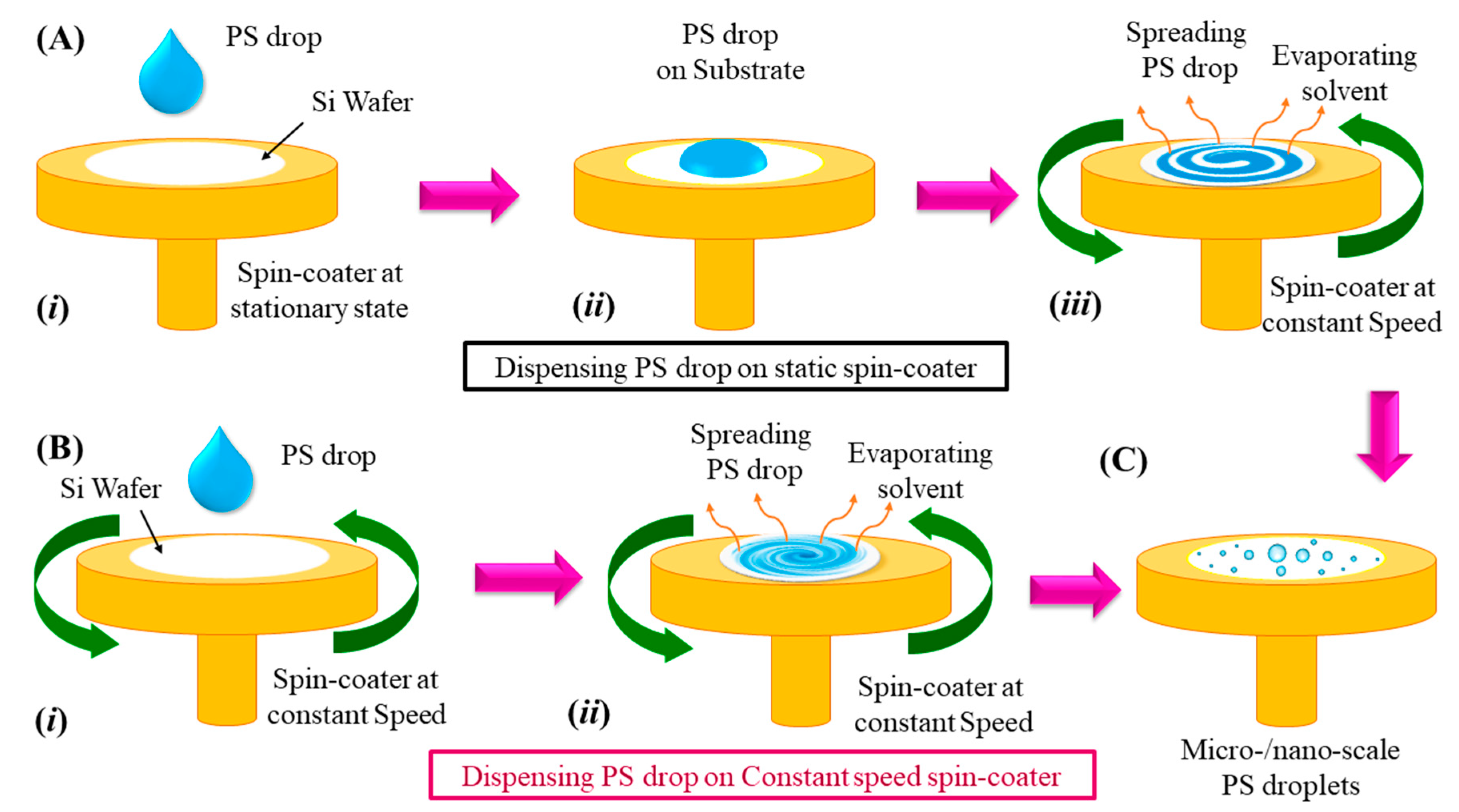
Figure 1. Schematic representation of the experimental set-up used to generate polystyrene-solvent (PS) solution-based micro–nano-scale droplets using spin dewetting, wherein the used solvent is volatile. Scheme (A) (iiii) represents the steps involved in micro–nano-scale droplet generation when the spin-coater started from a stationary state. Scheme (B) (i, ii) represents PS droplet generation steps when the spin-coater attained a constant speed and dispensed a PS drop. Scheme (C) shows the generated micro–nano-scale PS droplets in the last step of the spin-dewetting process. For both cases, the conditions of a ~10 μL PS drop and ~3000 rpm for ~120 s are used.
Processes 12 01562 g001
Figure 2. The components of the experimental set-up include the spin coater, optical microscope, and high-speed camera for the imaging installed on the microscope. The solid color arrows in the assembled set-up indicate all the individual components in the top row.
Processes 12 01562 g002
Figure 3. Schematic representation of steps (AD) of the spin-dewetting phenomenon when a PS–toluene solution drop has been dispensed on the spin-coater stage. Step (B) shows the spreading of the PS drop on the spinning coater with the rotational speed Ω and volatile solvent evaporation during the process. Step (C) shows the PS film formation on the substrate (1) placed on a spin-coater stage, where h 0 and h r , t the base and perturbed film (2) heights are used for the theoretical modeling to derive the film evolution equation. The solvent evaporated in the surrounding air (3) with the flux J . Step (D) shows the plethora of PS micro–nano-scale droplets, where λ m a x represents the space between two droplets.
Processes 12 01562 g003
Figure 4. Images show micrographs of the PS drop spin-dewetting process when the spin-coater was stationary (column i) and in motion (column ii) at the time of drop cast. Columns i and ii show steps (AF) of drop disintegration for 0.01 % and 0.1 % PS at an optimized speed of 1500   r p m , respectively. Curved arrows (yellow colored) in column ii (E,F) indicate trajectories followed by the generated droplets during spin dewetting in consecutive rotations. Plots (G,H) show the average droplet spacing ( λ m a x ) for 0.01 % and 0.1 % PS with time (t) measured in units of meters (m) and seconds (s).
Processes 12 01562 g004
Figure 5. The AFM images show the topography of the spin dewetted PS droplets. Row (A) represents topographies of singlet, doublet, triplet, and clusters of PS droplets formed in the spin dewetting at 3000 rpm. Row (B) shows the 3-D morphology of respective images of row (A) (iiv). Row (C) shows the line profiles (light blue colored lines in row (A) images) of PS dewetted droplets generated during the AFM scan.
Processes 12 01562 g005
Figure 6. Results obtained from the non-dimensional dispersion relation, depicting the variations in ω with k for a particular parameter variation and keeping others constant. Plot (A) shows the destabilizing influence of film thickness ( H ) variation on the system stability. Plot (B) shows the effect of Hamaker constant ( H a ) variation due to attractive interfacial interactions between the substrate and the film. Plot (C) shows the stabilizing contribution of interfacial tension through the inverse capillary ( C a ) number. Plot (D) shows the increasing system instability on increasing the rate of evaporation ( β ).
Processes 12 01562 g006
Figure 7. Parametric analysis of the spin-dewetting process and comparison between theoretically obtained length scales with experiments. Plot (A) represents the film thickness H variation with time ( t ) at different speeds (Ω), showing the steep decrease at increased rpm over the period. Plot (B) compares the generated droplet spacing ( λ m a x ) obtained from the theoretical model (colored lines) and the experiments (solid symbols). Plot (C) shows λ m a x with t at different H Plot (D) compares λ m a x obtained from theoretical and experimental analysis at different film thicknesses.
Processes 12 01562 g007
Disclaimer/Publisher’s Note: The statements, opinions and data contained in all publications are solely those of the individual author(s) and contributor(s) and not of MDPI and/or the editor(s). MDPI and/or the editor(s) disclaim responsibility for any injury to people or property resulting from any ideas, methods, instructions or products referred to in the content.