Article

Research on Multi-Layer Drilling Mud Reuse Technology

1
College of Energy and Chemical Engineering, Jingzhou University, Jingzhou 434000, China
2
Economics and Management School, Yangtze University, Jingzhou 434023, China
3
College of Chemistry & Environmental Engineering, Yangtze University, Jingzhou 434023, China
*
Author to whom correspondence should be addressed.
Processes 2024, 12(8), 1586; https://doi.org/10.3390/pr12081586 (registering DOI)
Submission received: 19 June 2024 / Revised: 25 July 2024 / Accepted: 26 July 2024 / Published: 29 July 2024
(This article belongs to the Section Energy Systems)

Abstract

:
Addressing the issues of low reuse rates and high waste content of drilling fluids commonly observed in oilfields, research on reuse technology based on utilizing the same system across different sections of the same well has been conducted. Using the F oilfield as a case study, the mechanism of wellbore destabilization was investigated through X-ray diffraction and scanning electron microscopy. Corresponding inhibitory anti-collapse drilling fluids for shallow layers were formulated, and a successful deep drilling fluid formula was developed by adding and replacing chemicals in the base fluid, thereby achieving the reuse of multilayered waste drilling fluids. Indoor evaluation results indicate that the high-temperature rheology of the modified deep drilling fluid is reasonable; the high-temperature inhibitor performs excellently, with a 16-h rolling recovery rate of ≥98%; and the settlement stability is robust, with a settlement ratio of 0.50 after 2 h of resting. These findings demonstrate that the drilling fluid possesses both excellent sand-carrying capacity and strong inhibitory effects, meeting the requirements for rapid drilling and wellbore stabilization in this stratum. This technology is straightforward and easy to implement, and it is expected to reduce treatment costs and promote efficient development within the block.

1. Introduction

With the ongoing advancements in oil exploration technology, drilling processes in complex formations, deep wells, and ultra-deep wells have become increasingly common, thereby imposing higher demands on drilling fluid technology [1,2,3]. Concurrently, the enforcement of domestic environmental protection laws has led to stringent controls on drilling fluid discharge, making environmentally friendly drilling fluids and non-hazardous treatment technologies focal points of research in this field. To mitigate the ecological impact of waste drilling fluids, reduce the development costs of oil and gas wells, and enhance the utilization rate of drilling fluids, it is imperative to study drilling fluid utilization technologies [4,5]. The reuse of drilling fluid necessitates exceptional inhibition properties, allowing fine drill cuttings to disperse within the fluid with minimal hydration. Additionally, it must possess robust thermal stability to withstand the temperatures of deeper formations. Also, since the specific gravity of the drilling fluid is usually calculated by estimating the formation pressure from cable or real-time logs or by using available data from nearby neighboring wells and seismic surveys. However, these data may result in an improper estimation of formation pressure, resulting in the incorrect setting of drilling fluid density, leading to formation fluids entering the wellbore and stuck drilling [6]. Traditional drilling fluid reuse technologies predominantly employ solid control equipment to eliminate low-quality solid phases. This approach aims to recover used drilling fluids or mix them with fresh slurry in specific ratios to explore reuse potential. Zhang et al. [7] assessed the changes in drilling fluid properties over a 15-day period by utilizing samples from three wells at various stages of the horizontal section alongside freshly prepared slurry in the laboratory, considering the geological conditions of the Sulig gas field. The results indicated that the conventional properties of the drilling fluid remained consistent with those at drilling completion. The proportion of usable components was high, and despite changes in rheology, the filtration loss and bentonite content were within acceptable limits, making it suitable for dilute slurry reforming. It is projected that recycling 1 m3 of drilling fluid could theoretically reduce costs by approximately 300 RMB. Cheng et al. [8], addressing the practical drilling conditions in the Beibu Gulf area, developed a robust solid-phase control technology by analyzing particle sizes and testing the performance of waste drilling fluid. This equipment is capable of detecting the particle size distribution of solid-phase particles in the waste drilling fluid and optimizing the configuration and parameters of the solid control equipment. It effectively purifies the waste drilling fluid and dilutes it with an appropriate amount of new slurry, ensuring that the drilling fluid’s performance meets the requirements for subsequent wells or well sections. However, challenges such as low applicability, proportion control difficulties, and poor operability persist [9,10]. Therefore, this study focuses on different sections of the same well to investigate the feasibility of reusing drilling fluids by merely adjusting the type or quantity of chemicals.
The stratigraphic characteristics of the F oilfield block are primarily composed of lacustrine carbonate rocks and minor clastic rocks, with extensive development of mudstone and muddy dolomite, interspersed with sand and gravel from adjacent terrigenous sources [11,12,13]. During the drilling of shallow strata of sandstone, such as sand Section 1 and Section 3, which exhibit good permeability, thick mud cakes readily form. Combined with high mechanical drilling speeds, drill cuttings are not sufficiently purified in time, leading to sticking issues. In contrast, drilling in deeper layers such as sand (Section 4) involves abundant muddy dolomite characterized by microfractures. These dolomites readily absorb water, expand, and disperse, generating high hydration pressure and increasing the risk of collapse, thus complicating the drilling process [14,15,16]. Inadequate matching of drilling fluid performance often results in the formation of thick mud cakes and shrinkage blockages, compromising the stability of the wellbore. Significant volumes of drilling fluid are emitted during single mining processes, and the waste drilling fluid discharged to the surface is not effectively treated, leading to low reuse rates, poor economic returns, and severe environmental pollution [17,18]. Therefore, this study investigates the issues of imperfect drilling fluid matching and low recycling rates in this oilfield block. It includes conducting physical property tests on field-sampled cores, developing a drilling fluid system tailored to the shallow strata based on the analysis, and exploring the feasibility of reuse. Ultimately, the study aims to establish a set of drilling fluid reuse technologies that meet the development demands of the oil reservoir in this block.

2. Materials and Methods

2.1. Materials

The materials used in this study are shown in Table 1.

2.2. Equipment

The main instruments used in this study are shown in Table 2.

2.3. Methods

2.3.1. Experimental Procedure

The appropriate amount of configured bentonite slurry was added to the drilling fluid cup, tap water was added and fixed onto the stirrer. Then, the speed was adjusted according to the formula, with the addition of shale inhibitor, flow regulator, viscosity increasing agent every 10 min. In addition, the filtration loss agent, aggravating agent, and viscosity reducing agent were all reduced, etc. After adding the chemicals and a duration of 30 min, the drilling fluid was configured for the performance test.
When the shallow drilling fluid is configured, 4% KY-1 (shale inhibitor) + 3.5% KJ-2 (fluid loss agent) + 0.25% KZ-1 (Tackifier) + 1.2% KN-1 (viscosity reducer) was added to the shallow drilling fluid formulation to make a deep drilling fluid. The full experimental flow of this paper is shown in Figure 1.

2.3.2. Basic Performance Testing of Drilling Fluids

(1)
Rheology and Filtration Loss Measurement
1)
The rheological properties and shear force of the drilling fluid were measured using a D6B six-speed rotational viscometer.
2)
While the API filtration loss was assessed with an NS-1 medium-pressure filtration loss meter. All experimental procedures were rigorously conducted in strict compliance with GB/T16783-1997 standards [19].
(2)
Expansion Rate Measurement
1)
A sample of 10.0 g of core powder, dried at (105 ± 2) °C for 4 h, was weighed, and the core was subsequently loaded into a core barrel and pressed at 10 MPa for 5 min to produce the test core.
2)
The core barrel was mounted on a shale expansibility tester KC-GDP1. The test liquid was then added to measure the change in core expansion height over time at room temperature, thereby evaluating the inhibition performance of the treatment agent and drilling fluid.

2.3.3. Analysis of the Well Wall Destabilization Mechanism

(1)
X-Diffraction Analysis
1)
X-diffraction was analyzed and tested using a D/max 2500 X-ray Diffraction. Approximately 3 g of core (dry weight > 5 g) was placed in a blast drying oven and dried at 45 °C for 24 h.
2)
After drying, samples for analysis were ground to 200 mesh, and the sediment was transferred to a 100 mL beaker, washed 2–3 times with deionized water, and placed in a vacuum desiccator to dry at 30 °C.
3)
The sample was then dried in a vacuum desiccator. The dried samples after de-drying were analyzed by X-ray diffraction.
(2)
SEM Analysis
1)
Scanning electron microscopy (SEM) was performed using a field-emission scanning electron microscope. The dried core was ground to below −5 μm, 2.0 g of core powder was weighed and placed into a beaker containing 40 mL of deionized water, and the pH was adjusted to 9.0.
2)
The sample was rinsed with deionized water 2–3 times and then placed in a vacuum drying oven at 30 °C for drying. The dried samples were examined by SEM.

2.3.4. Post-Conversion Performance Testing

(1)
Thermal stability
To make a deep drilling fluid 4% KY-1 (shale inhibitor) + 3.5% KJ-2 (fluid loss agent) + 0.25% KZ-1 (Tackifier) + 1.2% KN-1 (viscosity reducer) were added. The prepared drilling fluid is heated and rolled at 140 °C for 16 h. After completion of the heating process, the fluid is removed from the aging tank, and its rheological properties and filtration loss are tested.
(2)
Suspension stability
1)
The appropriate weight of deep drilling fluid was prepared to achieve the desired specific gravity.
2)
It was placed in a designated stainless steel tank and maintained at a specified temperature for a duration ranging from 2 to 24 h.
3)
The density or specific gravity of the upper (r1) and lower (r2) portions of the fluid column was then measured. The static settling factor (SF) was measured using formula (1). For example, if SF = 0.50, no static settling has occurred; if SF > 0.52, the static settling stability is considered poor [20].
S F = r 2 r 1 + r 2
where SF is the static sedimentation factor, r1 is the density of the upper part of drilling fluid column, g/cm3, and r2 is the density of the lower part of the drilling fluid column, g/cm3.
(3)
High Temperature Inhibitory
1)
The variable m1g, was dried to a constant weight (105 °C ± 3 °C) of the core particles and placed in the reaction kettle containing the drilling fluid to be tested for hot rolling experiments.
2)
Approximately 16 h after incubation of the liquid in the tank, the rock samples were are all transferred to the aperture of a 0.42 mm subsampling sieve, in the tank containing tap water.
3)
The tap water was continuously replaced to wash the sieve, until the tap water is clear. The rock samples were transferred to a porcelain evaporating dish that had been dried and weighed, and together they were placed in a 105 °C ± 3 °C blast oven to dry to a constant weight (accurately to 0.1 g).
4)
The sample was then removed from the desiccator and cooled to room temperature and weighed (accurate to 0.lg), denoted as mass m2. Three sets of parallel experiments were measured each time, and the average value was taken as the final result. The formula for calculating the heat roll recovery ω is shown in (2) [21].
ω = m 2 m 1 m × 100 %
where ω is the thermal roll recovery, %, m is the initial core particle mass, g, m1 is the mass of the empty weighing bottle, g, and m2 is the mass of core particles and weighing bottle after drying, g.

3. Results and Discussion

3.1. Analysis of the Well Wall Destabilization Mechanism

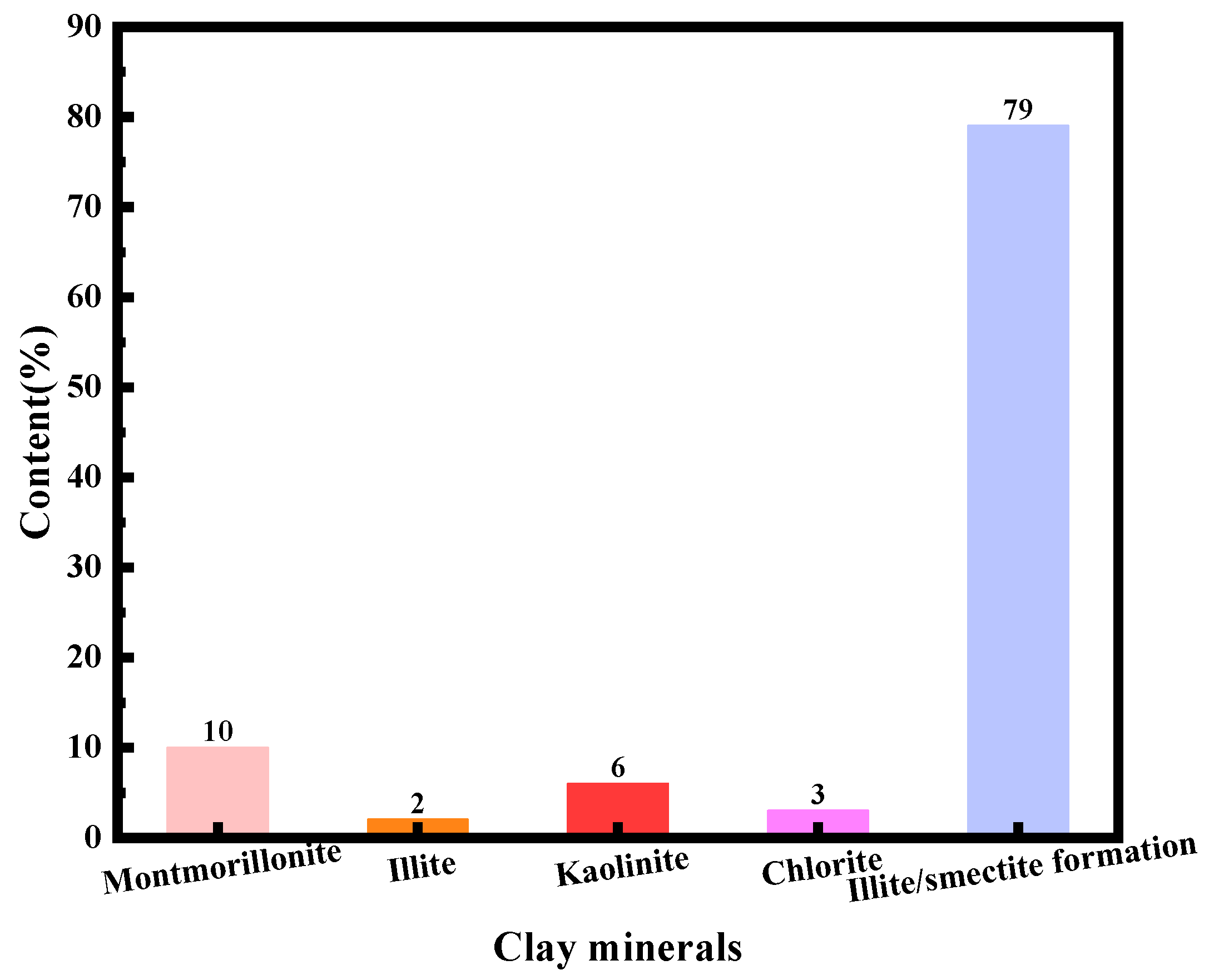
3.1.1. X-Diffraction Analysis
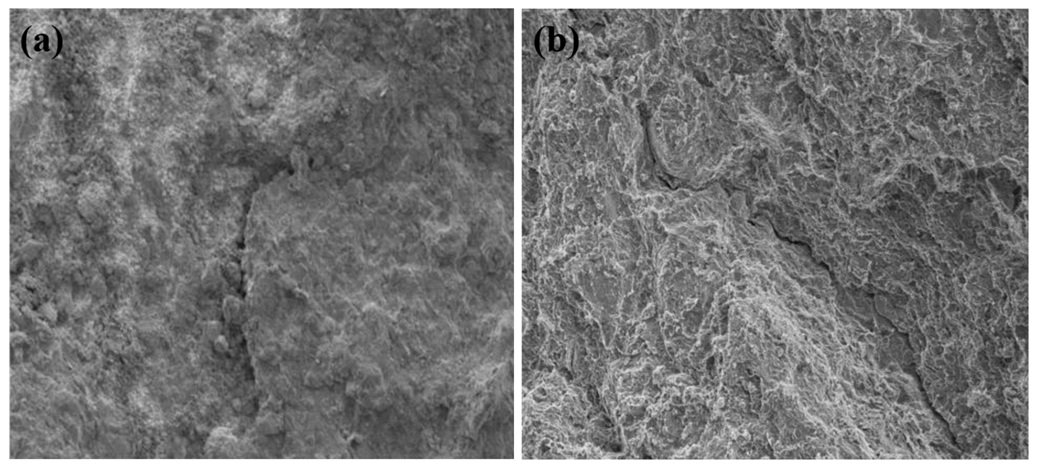
According to the “X-ray Diffraction Analysis Methods for Clay Minerals and Common Non-Clay Minerals in Sedimentary Rocks” (SY/T5163-2010), the mineral composition and clay content of rocks from the Sand III and Sand IV horizons were analyzed semi-quantitatively and quantitatively using a D/max 2500 X-ray diffractometer. The results are shown in Figure 2 and Figure 3. As illustrated in Figure 2 and Figure 3, the core samples are predominantly composed of clay, accounting for up to 50.00%. This is followed by sodium feldspar and quartz, constituting 24.37% and 19.77%, respectively, with minor amounts of potassium feldspar and calcite. The clay composition within the shale mainly consists of mixed layers of illite and montmorillonite, with some development of montmorillonite. Illite accounts for about 2%, and other clay minerals are present in smaller amounts. This indicates that these rocks have a strong hydration and swelling capacity, making it easy for drilling fluids to penetrate cracks upon contact with water-based drilling fluids, thereby increasing the stress intensity at the fracture tips. Microfractures gradually extend under high stress and external forces, reducing the effective stress around the wellbore. This further expansion of microfractures leads to wellbore instability [22].

3.1.2. SEM Analysis

From the results of X-diffraction analysis, it can be seen that the rock minerals are dominated by clay minerals, and the clay mineral composition is dominated by an aemon mixed layer, which indicates that the stratigraphic rocks are easy to be hydrated, causing the rock strength to decrease, resulting in the spalling and falling off of the well wall and destabilizing and collapsing. Therefore, in this section, the cores were immersed in water, and the microstructure of the immersed core surface was analyzed by a scanning electron microscope (SEM) to further investigate the destabilization mechanism.
The surface morphology of the core before and after water immersion is depicted in Figure 4. As illustrated in Figure 4, the mineral surface is rough, characterized by a few microcracks and powdery particles. The overall surface is angular, and the cohesion between minerals is tight (Figure 4a). After 24 h of water immersion, the surface of the mud shale core exhibits a fractured morphology, with a rough and irregular texture. This is attributed to the fact that water is prone to invade along the nano-micron pore cracks in the formation, causing reservoir damage, causing the hydration of clay minerals while increasing the pore pressure in the cracks, and exacerbating the collapse of the well wall to fall off the block (Figure 4b). Thus, the primary cause of well wall instability is the partial hydration and expansion of the clay in the rock samples [23].

3.2. Shallow Anti-Collapse Drilling Fluid Construction

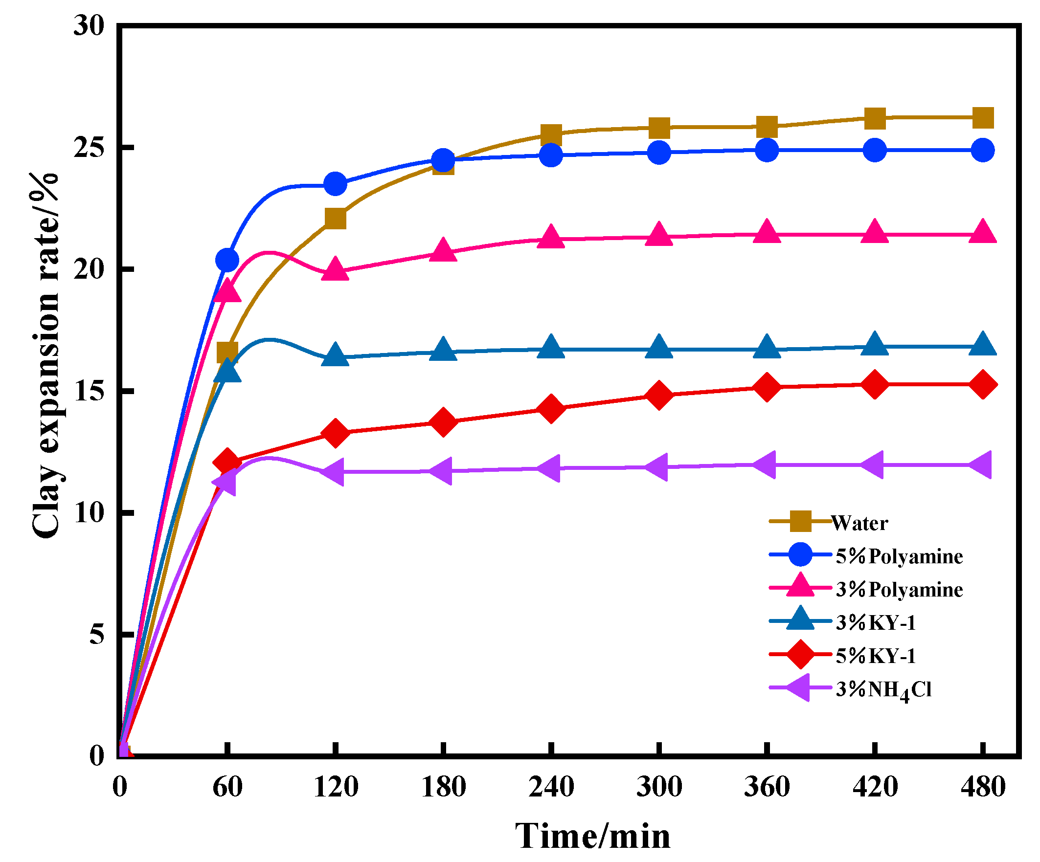
3.2.1. Inhibitor Optimization

To address the issue of the mudstone in the shallow section easily forming slurry and to emphasize the strong inhibitory properties of anti-collapse drilling fluid, various inhibitory salts were evaluated for their inhibitory effects using a clay swelling experiment after the shallow core was pressed and sliced [24,25]. The experimental results are presented in Figure 5. As shown in Figure 5, the order of inhibitory effectiveness of the three inhibitors is NH4Cl > KY-1 > Polyamine. However, due to the instability of NH4Cl at high temperatures, which can easily decompose and produce irritating odor gases, KS-1, a high-temperature-resistant salt developed in the laboratory, is more suitable for this drilling fluid system. Consequently, KY-1 was selected as the inhibiting salt [26,27].

3.2.2. Tackifier Optimization

During the drilling operation, to ensure that the drill cuttings are flushed from the bottom of the well and carried up to the surface, and to smoothly transfer the pumping horsepower to the water hole of the drill bit to break the rock, the selected drilling fluid must have good rheological properties, such as appropriate viscosity, dynamic plasticity ratio, and shear dilution. Therefore, the selected drilling fluid must have good rheological properties, such as appropriate apparent viscosity, dynamic plastic ratio, and shear dilution. Adding the necessary viscosity builder to the base stock is a key factor in upgrading the drilling fluid. Adding the necessary viscosity builder to the base stock is one way to improve the rheology of the drilling fluid [28,29]. The addition of viscosity builders can enhance the rheology of drilling fluid. Using a 3.0% base slurry as the foundation fluid, various types of viscosity builders were added to optimize the performance of the viscosity enhancer. The experimental results are presented in Table 3. As indicated in Table 3, KZ-1 exhibits a more significant viscosity-enhancing effect compared to KZ-2. Therefore, KZ-1 was selected as the primary viscosity-enhancing agent for the anti-collapse drilling fluid.

3.2.3. Shallow Drilling Fluid System Formulation

A set of high-performance drilling fluids for shallow formations was formulated by preferentially selecting two primary treatment agents and combining them with a conventional salt-resistant filter-loss reducer, a flow regulator, and other functional treatment agents. The formulation consists of 3% bentonite + 0.2% flow regulator + 3.5% KJ-1 + 1% KY-1 + 0.25% KZ-1 + 2.5% weighting agent (density = 1.400 g/cm3). The basic performance metrics are presented in Table 4 [30,31].
As demonstrated in Table 4, the filtration loss of the weighted anti-collapse drilling fluid meets the basic requirements for field drilling construction (≤4.0 mL). Additionally, the plastic viscosity increased slightly after weighting; however, this did not impact the overall sand-carrying capacity.

3.3. Feasibility Study

Transitioning from shallow to deep involves higher clay mineral content and formation temperatures, necessitating stricter requirements on drilling fluid rheology, filtration loss, and anti-collapse performance. Consequently, there is a heightened demand for temperature resistance and inhibitors [32,33]. Hence, the transformation strategy is outlined as follows: ① Introduce new inhibitors or increase the dosage of existing inhibitors to enhance the inhibition and anti-collapse capabilities of the drilling fluid. ② Utilize the high-temperature composite viscosifier KZ-1 to enhance sand suspension and rock transport in the drilling fluid at elevated temperatures. ③ Incorporate a suitable amount of viscosifier to mitigate issues such as high-temperature dispersion, agglomeration, and passivation induced by elevated drilling fluid temperatures, thereby enhancing rheological properties and viscosity. ④ Employ a new high-temperature compound viscosity builder to enhance rheology, reduce filtration loss, and enhance anti-collapse performance, thereby improving overall rheological properties and viscosity. Replace the original KJ-1 filter loss reducer with the new temperature-resistant KJ-2 filter loss reducer to satisfy requirements for drilling fluid rheology, water loss control, formation stability, and anti-collapse properties at high temperatures [34,35].

3.4. Evaluation of the Performance of Deep Anti-Collapse Drilling Fluids

3.4.1. Thermal Stability Evaluation

Because the application depth of the new anti-collapse drilling fluid is about 4200 m, the experimental setting temperature is 140°. The new anti-collapse drilling fluid is hot rolled at 140° for 16 h and then taken out, cooled down to room temperature, and then the high-temperature rheological properties are measured, and the experimental results are shown in Table 5 and Figure 6.
As shown in Table 5, the viscosity of the new anti-collapse drilling fluid did not change much after hot rolling at 140 °C, and the filtration vector was reduced from 4.1 mL to 3.0 mL, which indicates that the configured new slurry has a better filtration loss and wall-making, and its rheology and rock-carrying capacity are in line with the construction requirements. Meanwhile, from the high temperature and high pressure water loss of 9.5 mL and the mud cake diagram (Figure 6), it can be seen that the mud cake is thin and dense, indicating that the addition of an anti-temperature and filtration loss reducer effectively plugs the tiny pores in the drilling fluid, and it can reduce the infiltration of filtrate into the formation to meet the needs of the site.

3.4.2. Suspension Stability Evaluation

Settlement stability reflects the ability of the weighting agent particles in the weighted drilling fluid to maintain uniform distribution in the drilling fluid [36]. The new anti-collapse drilling fluid was weighted to the target density (ρ = 1.540 g/cm3) in a beaker. The suspension stability was determined using the experimental method described in Section 2.3.3, with the results presented in Table 6. As shown in Table 6, the weighted drilling fluid exhibits excellent suspension stability; after standing for 2 h, there is no change in the specific gravity between the upper and lower layers, and the static settling factors remain at 0.5 [37,38,39]. As a result, the converted drilling fluid has better suspension stability and can effectively carry drill cuttings, purify the borehole, and keep the well wall stable.

3.4.3. Evaluation of Suppression Performance

High-temperature inhibition can respond to the guarantee that the drilling fluid can function properly in deep-well operations [40]. The transformed deep drilling fluids were measured using the experimental method in Section 2.3.2. The 140 °C core rolling recoveries of the new anti-collapse drilling fluid are presented in Figure 7. As shown in Figure 7, the drilling fluid exhibits excellent inhibition, with hot rolling recoveries exceeding 98%. This indicates that the converted drilling fluid maintains strong inhibition under simulated high-temperature (140 °C) conditions. It indicates that the anti-temperature inhibitor in the transformed anti-temperature anti-collapse water-based drilling fluid can inhibit the dispersion of mud shale hydration for a longer period of time, suggesting that it has excellent shale hydration inhibition properties.

3.5. Comparison with Previous Studies on Innovativeness

The innovative nature of this paper can be more easily understood by comparing it with previous similar studies. Therefore, a list form was used to compare this study with previous studies, and the results are shown in Table 7. As illustrated in Table 7, this study markedly diverges from previous research in terms of technical implementation methods, applicability, and respective advantages and disadvantages. The prior research predominantly involved the proportional mixing of old and new slurry. In contrast, this study focuses on the reuse of old drilling fluid slurry by enhancing the dosage and adjusting the type of original formulated agents. Additionally, due to the varying performance requirements of drilling fluids across different wells, the previous study’s control over the ratio of old to new slurry posed challenges in terms of applicability and economic feasibility. This study utilizes shallow and deep drilling fluids from the same well as experimental subjects. The direct addition and replacement of dosages and chemicals simplifies operation and enhances economic efficiency for the same well. However, the feasibility of this method across different wells requires validation through subsequent research.

4. Conclusions

(1)
Through X-diffraction and scanning electron microscopy, the cause of well wall instability was clarified to be that the rock physical properties of the formation were mainly immonite and the mud shale reservoir was prone to hydration and expansion, which led to well wall instability;
(2)
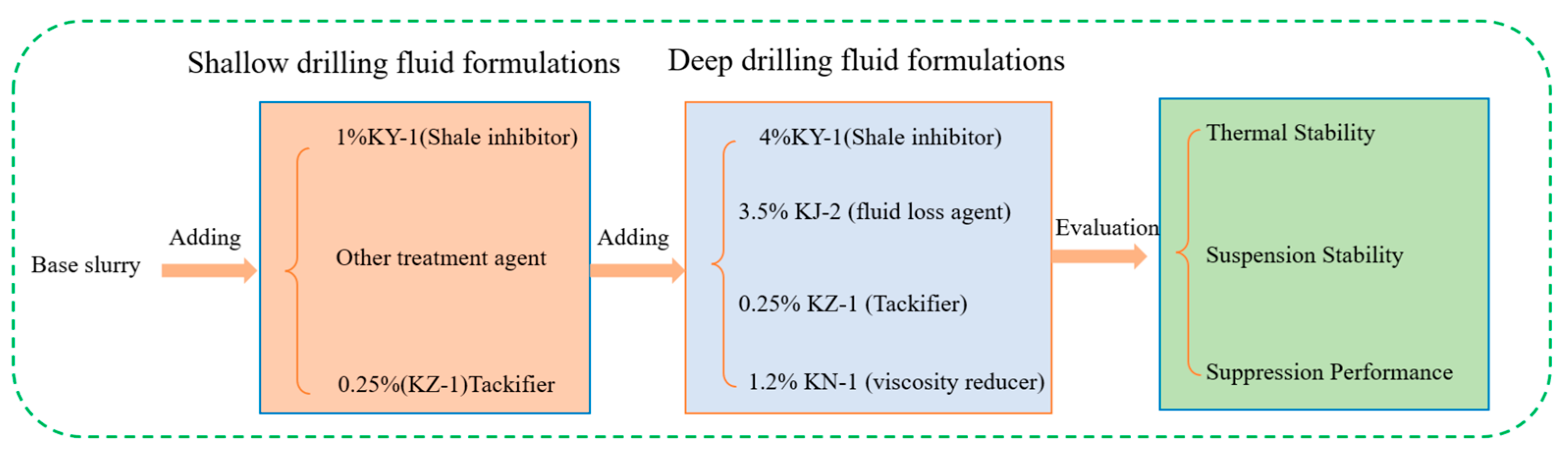
The key treatment agents, such as shale inhibitor and viscosity builder, were selected to develop a shallow anti-collapse drilling fluid formula for the F oilfield block: 3.0% bentonite + 0.2% flow regulator + 3.5% KJ-1 + 1% KY-1 + 0.25% KZ-1 + 2.5% weighting agent (ρ = 1.400 g/cm3), and at the same time, a weighting agent (ρ = 1.400 g/cm3) was developed, and based on this formulation, the idea of reuse by increasing the concentration or replacing the agent was proposed;
(3)
The shallow anti-collapsing drilling fluid formula of F oilfield block was converted into a deep drilling fluid formula by adding 4% KY-1 + 3.5% KJ-2 + 0.25% KZ-1 + 1.2% KN-1, and the performance evaluation results showed that the converted deep drilling fluid formula had good high-temperature stability and suspension stability at 140 °C, and it had certain value for field application.
(4)
The future drilling fluid reuse technology should focus on the development of different high-performance temperature-resistant materials with a high degree of synergistic effect. While ensuring the performance requirements of drilling operations, the reuse process should be simplified as much as possible by increasing the dosage of the original agent of the old slurry or replacing the agent, so as to ensure the feasibility and economy of the field operations.

Author Contributions

Methodology, J.H., L.W. and F.L.; Validation, J.H.; Investigation, J.H.; Resources, F.L.; Data curation, L.W. All authors have read and agreed to the published version of the manuscript.

Funding

This research received no external funding.

Data Availability Statement

Data are contained within the article.

Conflicts of Interest

The authors declare no conflict of interest.

References

  1. Yang, P. Key technology of drilling fluid for well factory-like operation. Spec. Oil Gas Reserv. 2019, 26, 10–15. [Google Scholar]
  2. Sun, J.S.; Liu, J.P.; Liu, Y. Status quo of water base drilling fluid technology for shale gas drilling in china and abroad and its developing trend in China. Drill. Fluid Complet. Fluid 2016, 33, 1–8. [Google Scholar]
  3. Ratner, M.; Tiemann, M. An Overview of Unconventional Oil and Natural Gas: Resources and Federal Actions. 2014. Available online: https://www.ourenergypolicy.org/wp-content/uploads/2013/07/R43148.pdf (accessed on 18 June 2024).
  4. Knapik, E.; Chruszcz-Lipska, K.; Lukanko, L.; Wysocki, S. Reuse of Flowback Water from Hydraulic Fracturing for Drilling Mud Preparation and Secondary Hydrocarbon Recovery. Energies 2021, 14, 5921. [Google Scholar] [CrossRef]
  5. Zarkani, H.M.A.; Mezher, T.; El-Fadel, M. Life cycle assessment in the petroleum industry: A systematic framework towards improved environmental performance. J. Clean. Prod. 2023, 408, 137196. [Google Scholar] [CrossRef]
  6. Fotios, N.Z.; Nikolaos, C.K. Detection methodologies on oil and gas kick: A systematic review. Int. J. Oil Gas Coal Technol. 2022, 33, 1–19. [Google Scholar]
  7. Zhang, X.; Zhao, F.C.; Cao, X.H.; Wei, Y.H.; Xu, Y. Recycling of drilling fluids in Sulige gasfield. Drill. Fluid Complet. Fluid 2015, 32, 99–102. [Google Scholar]
  8. Cheng, Y.S.; Zhang, L.Q.; Mo, T.M.; Xiang, X.; Zhang, M. Solids Control and Re-use of Water Base Drilling Fluid in Beibu Gulf. Drill. Fluid Complet. Fluid 2016, 33, 60–63. [Google Scholar]
  9. Hu, J.J.; Sun, Q.; Xia, X.C.; Wei, Z.L.; Ji, T.; Xiang, T. Development and Application of Environment- Friendly Drilling Fluid GR EEN-DRILL. Pet. Drill. Tech. 2014, 42, 75–79. [Google Scholar]
  10. Lima, R.I.C.; Da, S.D.C.; Neto, A.D.W.; Aum, T.N.D.; Dantas, T.N.D. Obtaining a stable olefin-based drilling fluid using non-treated produced water. J. Dispers. Sci. Technol. 2023, 45, 609–617. [Google Scholar] [CrossRef]
  11. Yu, C.W.; Yang, S.J.; Zhao, S.J. Borehole wall strengthening with drilling fluids in shale gas drilling. Drill. Fluid Complet. Fluid 2018, 35, 49–54. [Google Scholar]
  12. Pereira, L.B.; Sad, C.M.S.; Castro, E.V.R.; Filgueiras, P.R.; Lacerda, V. Environmental impacts related to drilling fluid waste and treatment methods: A critical review. Fuel 2021, 310, 122301. [Google Scholar] [CrossRef]
  13. Ma, S.K.; Zhang, G.L.; Shi, C.H.; Dong, Q.Y.; Ji, T. Achieving Practical Venue Recycle of Waste Oil-Based Drilling Fluids with Vacuum Distillation Technology. ACS Omega 2023, 8, 16306–16314. [Google Scholar] [CrossRef] [PubMed]
  14. Fan, B.; He, S.; Feng, H.Z.; Zhou, D.Z.; Xing, X.J.; Yue, Q.S. Reusable Water-Based Drilling Fluid and lts Application in Bohai Bay Oilfield. Technol. Superv. Pet. Ind. 2022, 38, 47–50. [Google Scholar]
  15. Liu, D.D.; Liang, X.; Wu, M.; Li, X.B. Removal of ultrafine colloidal particles from shale gas fracturing flowback fluid by microbubble-intensified flocculation: Effect of microbubble size. J. Water Process Eng. 2023, 52, 103541. [Google Scholar] [CrossRef]
  16. Gong, W. Reuse Technology of Synthetic Base Drilling Fluid in Yongjin 3 Block. Mod. Indusrial Econ. Informationization 2022, 12, 332–334. [Google Scholar]
  17. Asim, N.; Badiei, M.; Torkashvand, M.; Mohammad, M.; Alghoul, M.A.; Gasaymeh, S.S.; Sopian, K. Wastes from the petroleum industries as sustainable resource materials in construction sectors: Opportunities, limitations, and directions. J. Clean. Prod. 2021, 284, 125459. [Google Scholar] [CrossRef]
  18. Alimonti, C.; Gnoni, A.A. Harnessing the fluids heat to improve mature oil field: The Villafortuna-Trecate case study. J. Pet. Sci. Eng. 2015, 125, 256–262. [Google Scholar] [CrossRef]
  19. GB/T16783-1997; Procedure for Field Testing Water-Based Drilling Fluids. Standards Press of China: Beijing, China, 1997.
  20. Ai, L.; Gao, Y.W.; Ouyang, Y.; Xin, Q.Q.; Zhou, Y. Low damage highly inhibitive water based drilling fluid for drilling shale oil reservoir. Drill. Fluid Complet. Fluid 2023, 40, 602–610. [Google Scholar]
  21. Ihejirika, B.; Dosunmu, A.; Eme, C. Performance evaluationof guar gum as a carrier fluid for hydraulic fracturing. SPE Niger. Annu. Int. Conf. Exhib. 2015, 2015, SPE-178297. [Google Scholar]
  22. Ye, C.; Ren, T.; Yin, Z.B.; Li, C.; Bai, Y. Wellbore stability mechanism of fractured formation in the thrust belt of southern margin of junggar basin. J. Southwest Pet. Univ. (Sci. Technol. Ed.) 2023, 45, 95–103. [Google Scholar]
  23. Bayat, A.E.; Shams, R. Appraising the impacts of SiO2, ZnO and TiO2 nanoparticles on rheological properties and shale inhibition of water-based drilling muds. Colloids Surf. A-Physicochem. Eng. Asp. 2019, 581, 123792. [Google Scholar] [CrossRef]
  24. Moustafa, A.M.; Shehata, A.S.; Shehata, A.I.; Hanafy, A.A. Reuse of Abandoned oil and gas wells for Power generation in Western Dessert and Gulf of Suez fields of Egypt. Energy Rep. 2022, 8, 1349–1360. [Google Scholar] [CrossRef]
  25. Nascentes, C.L.; Murata, V.V.; Oliveira-lopes, L.C. Mathematical modeling of solids-drilling fluid separation in shale shakers in oil fields: A state of art review. J. Pet. Sci. Eng. 2022, 208, 109270. [Google Scholar] [CrossRef]
  26. Liu, F.; Li, Y.F.; Wang, X.W.; Xia, Z.Z. Preparation and Properties of Reversible Emulsion Drilling Fluid Stabilized by Modified Nanocrystalline Cellulose. Molecules 2024, 29, 1269. [Google Scholar] [CrossRef] [PubMed]
  27. Cao, J.; Xu, P.C.; Chen, L.; Song, W.G.; Yu, D.Z.; Zhang, J.F.; Zheng, X.; Yang, J.D. Development of a novel environmentally friendly drilling fluid system and field trial. Fresenius Environ. Bull. 2020, 29, 2526–2533. [Google Scholar]
  28. Zhao, X.Y.; Li, D.Q.; Zhu, H.M.; Ma, J.Y.; An, Y.X. Advanced developments in environmentally friendly lubricants for water-based drilling fluid: A review. RSC Adv. 2022, 12, 22853–22868. [Google Scholar] [CrossRef] [PubMed]
  29. Mateus, L.; Taborda, E.A.; Moreno-Castilla, C.; López- Ramón, M.V.; Franco, C.A.; Cortés, F.B. Extra-Heavy Crude Oil Viscosity Reduction Using and Reusing Magnetic Copper Ferrite Nanospheres. Processes 2021, 9, 175. [Google Scholar] [CrossRef]
  30. Li, J.X.; Zhang, S.J.; Li, L.; Sun, D.S.; Zhang, C.; Wang, T. Application of Environmentally Friendly High Performance Water Base Muds in Ultra Depp Well Drilling in Piedmont Area. Drill. Fluid Complet. Fluid 2017, 34, 20–26. [Google Scholar]
  31. Alvi, M.A.; Belayneh, M.; Fjelde, K.K.; Saasen, A.; Bandyopadhyay, S. Effect of hydrophobic iron oxide nanoparticles on the properties of oil-based drilling fluid. Energy Resour. Technol.-Trans. Asme 2021, 143, 043001. [Google Scholar] [CrossRef]
  32. Ajemigbitse, M.A.; Cannon, F.S.; Klima, M.S.; Furness, J.C.; Wunz, C.; Warner, N.R. Raw material recovery from hydraulic fracturing residual solid waste with implications for sustainability and radioactive waste disposal. Environ. Sci.-Process. Impacts 2019, 21, 308–323. [Google Scholar] [CrossRef] [PubMed]
  33. Caulk, R.A.; Tomac, I. Reuse of abandoned oil and gas wells for geothermal energy production. Renew. Energy 2017, 112, 388–397. [Google Scholar] [CrossRef]
  34. Konate, N.; Salehi, S. Experimental Investigation of Inhibitive Drilling Fluids Performance: Case Studies from United States Shale Basins. Energies 2020, 13, 5142. [Google Scholar] [CrossRef]
  35. Akpan, E.U.; Enyi, G.C.; Nasr, G.; Yahaya, A.A.; Ahmadu, A.A.; Saidu, B. Water-based drilling fluids for high-temperature applications and water-sensitive and dispersible shale formations. J. Pet. Sci. Eng. 2019, 175, 1028–1038. [Google Scholar] [CrossRef]
  36. Yalman, E.; Federer-Kovacs, G.; Depci, T.; Al Khalaf Aylikci, V.; Aydin, M.G. Development of novel inhibitive water-based drilling muds for oil and gas field applications. J. Pet. Sci. Eng. 2022, 210, 109907. [Google Scholar] [CrossRef]
  37. Carrero-Parreño, A.; Onishi, V.C.; Salcedo-Díaz, R.; Ruiz-Femenia, R.; Fraga, E.S.; Caballero, J.A.; Reyes-Labarta, J.A. Optimal pretreatment system of flowback water from shale gas production. Industrial & Engineering Chemistry Research. Ind. Eng. Chem. Res. 2017, 56, 4386–4398. [Google Scholar]
  38. Norouzi, M.; Rashidi, F.; Noorollashi, Y.; Qom, H.F. CuO/water and Al2O3/water nanofluids as working fluid in an abandoned oil well to improve thermal performance in the seawater desalination process. J. Taiwan Inst. Chem. Eng. 2023, 144, 104754. [Google Scholar] [CrossRef]
  39. Oyedoh, E.; Odumugbo, C.; Ebewel, E.O. Suitability of nigerian bentonite in drilling fluid formulatio. Int. J. Eng. Res. Afr. 2016, 24, 26–34. [Google Scholar] [CrossRef]
  40. Geng, T.; Qiu, Z.S.; Tang, Z.C.; Zhao, X.; Miao, H.L. The development and application of high temperature resistant and strong inhibitive water-based drilling fluid for deepwater drilling. Pet. Drill. Tech. 2019, 47, 82–88. [Google Scholar]
Figure 1. Flow chart of the whole experiment.
Processes 12 01586 g001
Figure 2. Analysis of mineral composition and content in shallow rock samples.
Processes 12 01586 g002
Figure 3. Analysis of clay mineral composition and content in rock samples.
Processes 12 01586 g003
Figure 4. Scanning electron microscope image of a rock sample. (a) Morphological characteristics of the core surface(100 μm). (b) Morphological characteristics of the core surface after soaking in water (100 μm).
Processes 12 01586 g004
Figure 5. Comparison of the hydration and swelling effects of different inhibitors.
Processes 12 01586 g005
Figure 6. Filter cake of new anti-collapse drilling fluid.
Processes 12 01586 g006
Figure 7. Hot rolling recovery of new drilling fluid at 140 °C.
Processes 12 01586 g007
Table 1. Experimental material types and manufacturers.
Material NameManufacturer
CoreThe shallow and deep sections of oil field
bentoniteZhejiang Fenghong New Material Co., Ltd., Huzhou, China
Aggravating agentWen’an Zhongde Chemical Co., Ltd., Langfang, China
CMCShandong Zhengyang New Material Technology Co., Ltd., Liaocheng, China
PAMShandong Zhengyang New Material Technology Co., Ltd., Liaocheng, China
KY-1 (Shale inhibitor)College of Energy and Chemical Engineering, Jingzhou University, Jingzhou, China
KJ-1, KJ-2 (Fluid loss agent)College of Energy and Chemical Engineering, Jingzhou University, Jingzhou, China
KZ-1, kZ-2 (Tackifier)College of Energy and Chemical Engineering, Jingzhou University, Jingzhou, China
KN-1 (Viscosity reducer)College of Energy and Chemical Engineering, Jingzhou University, Jingzhou, China
Table 2. Types and manufacturers of experimental equipment.
Equipment NameManufacturer
Flip Type Pulper PJ-10LXianxian Tianjian Instrument Co., Ltd., Cangzhou, China
Mid-pressure Drilling Fluid Filter Press ZNS-2Xianxian Tianjian Instrument Co., Ltd., Cangzhou, China
Rotational Viscometer D6BXianxian Tianjian Instrument Co., Ltd., Cangzhou, China
Shale Expansibility Tester KC-GDP1Xianxian Tianjian Instrument Co., Ltd., Cangzhou, China
Liquid Density Meter YYMXianxian Tianjian Instrument Co., Ltd., Cangzhou, China
Roller Oven GRL-BX3Qingdao Senxin Electromechanical Equipment Co., Ltd., Qingdao, China
Reaction Kettle LHG-3Qingdao Senxin Electromechanical Equipment Co., Ltd., Qingdao, China
D/max 2500 X-ray DiffractionJapan RIKEN Co., Ltd., Qingdao, China, Tokyo, Japan
Field Emission Scanning Electron MicroscopeHitachi, Japan, Beijing, China
Table 3. Comparison of properties of different tackifiers.
TackifierContentAV/mPa·sPV/mPa·sGel/PaYP/PaYP/PVn
KZ-10.25%21.013.01.798.190.630.53
KZ-212.08.01.024.090.510.58
Table 4. Optimized formulation system and basic performance of raw collapse drilling fluid.
AggravatingAV/mPa·sPV/mPa·sYP/PaYP/PVnFLAPI/mLρ/g/cm3
Weighted28.022.06.160.280.725.21.073
Unweighted47.537.510.130.270.724.01.401
Table 5. Comparison of the performance of new anti-collapse drilling fluids before and after hot rolling (140 °C).
StateAV/mPa·sPV/mPa·sYP/PaYP/PVnFLAPI/mLFLHTHP/mL
Before78.575.07.500.100.944.1/
After75.069.0.6.900.100.893.09.5
Table 6. Suspension stability after weighting of new anti-collapse drilling fluid.
ρtop (g/cm3)ρbottom (g/cm3)SF
1.5401.5400.50
1.5401.5410.50
Table 7. Comparison of this study with previous research methods.
Research ObjectTechnical ApproachAdvantageDisadvantage
Previous studyMixing the old pulp with the new pulp proportionallyWorks well with two different wells, more mature technologyLow applicability, difficult scale control, poor maneuverability, and economy
Our studyAddition of original/replacement agent to old pulpSimple operation, good economy, applicable to different sections of the same wellTechnology universality needs to be proven
Disclaimer/Publisher’s Note: The statements, opinions and data contained in all publications are solely those of the individual author(s) and contributor(s) and not of MDPI and/or the editor(s). MDPI and/or the editor(s) disclaim responsibility for any injury to people or property resulting from any ideas, methods, instructions or products referred to in the content.

