Abstract
The present investigation focuses on enhancing the efficiency of a vapor compression refrigeration system (VCRS) by proposing a Multiple Input Multiple Output (MIMO) control strategy based on the evaporator’s two-phase length and superheat temperature. A moving boundary dynamic model for the VCRS is implemented using the Thermosys Matlab Toolbox. The study analyzes the influence of actuation parameters, specifically compressor speed and expansion valve opening, on control parameters, namely two-phase length and superheat temperature. A comprehensive analysis based on the first and second laws of thermodynamics is conducted across a wide range of operating conditions. Simulation results demonstrate that two-phase length can be effectively utilized as a control parameter by selecting operating points that maximize the system efficiency. Additionally, the study reveals that extending the evaporator’s two-phase length to 80–90% of its limit increases system efficiency, enabling a reduction in compressor speed while maintaining the cooling capacity.
1. Introduction
Cooling and refrigeration systems consume around 17% of the worldwide electricity [1]. Enhancing the performance of these systems can lead to minimizing the energy consumption of their components and, consequently, significant cost savings for the industrial sector. Investigations to improve the efficiency of vapor compression refrigeration systems (VCRS) through various control strategies require a substantial understanding of the physical phenomena, particularly the mass and heat transfer, as well as fluid dynamics that occur throughout the entire refrigeration cycle.
The concept of variable cooling capacity control to improve refrigeration systems by using a variable-velocity compressor was proposed more than 50 years ago by [2]. Currently, a conventional VCRS shows an energy saving of about 30% solely by means of the implementation of variable speed compressor technology [3,4]. For instance, in [5], the authors studied air-conditioner systems with different thermal loads. Their experimental results showed that the energy saving can increase by 38.9% by using a variable speed driver for both the compressor and fans compared to single-speed equipment. Additionally, increasing the efficiency of variable-speed refrigeration systems as well as their cooling capacity can also be achieved through the use of electronic expansion valves (EEVs). The improvement in the performance of refrigeration processes is achieved because a system with variable elements (compressor and EEV) can adapt to the required demands, since changes in compressor speed allow the system to operate based on changing thermal load [6,7]. Experimental attempts have been performed on the implementation of both techniques, a variable speed compressor and changing the stroke of an electronic expansion valve, simultaneously, leading to the conclusion of COP increasing at low compressor speed and by decreasing expansion valve opening at each speed [8].
Parametric studies of actuation variables, such as compressor speed and valve opening, can be challenging to carry out experimentally due to the long-running times of a single experiment. Consequently, some authors propose these studies through numerical models that can simulate the VCRS under different operating conditions and perform extensive parametric analyses to improve the efficiency of such systems [9,10,11,12]. Therefore, building robust numerical models is mandatory for a sound physical insight into VCRS’s, which was achieved in [13], where authors developed a computational tool for the design of a vapor-compression liquid-cooled-chiller unit. Here, a case study is conducted to analyze the effects of refrigerant charge, subcooling level, and expansion valve openings on the performance of the unit. This analysis was experimentally validated. Simulations conducted in [14] showed specifically that COP decreased when compressor speed was increased because of higher power consumption in spite of the increase in refrigeration effect. These simulations presented a relationship between compressor speed and EEV opening which achieves maximum system performance. Furthermore, ref. [15] developed a dynamic model to control a variable refrigerant flow system (VRFs) including a variable speed compressor, EEV, and sub-cooler. The effect of coupling between compressor speed and EEV opening on the performance and stability of the VRFs was studied. They found that the optimum energy efficiency ratio (EER) occurred at a narrow EEV opening under part-load conditions. The narrow EEV opening influenced the amount of refrigerant in the subcool phase at a specific compressor speed, leading to an increase in refrigeration capacity. There are different approaches to modeling these types of systems, specifically, three approaches are commonly used in the literature: lumped parameter models, spatially distributed approaches (finite volume/finite difference methods), and moving boundary models [16].
Likewise, several theoretical studies focus on controlling methods using actuation variables. For instance, in [17], superheating was controlled by a thermostatic expansion valve. The variation in cooling capacity using variable-speed compressors equipped with an electronic expansion valve requires intelligent controllers to achieve optimum performance. In this context, ref. [18] developed and validated a dynamic simulation model for the identification and control of vapor compression refrigeration systems over a broad range of operations. A breadboard refrigeration system, comprising a variable-speed compressor and an EEV, was used to gather the required experimental data for both system identification and model validation. The model was found to reproduce experimental trends of the working pressures accurately, even under conditions far from the operation point used in system identification, with maximum discrepancies between calculated and measured values within a 5% error margin.
There are well-established control methods to stabilize the VCRSs for a given operating point. However, it is challenging to design such local controllers to handle large transient heat flux and load disturbances, due to complex coupling and constraints, and potential violation of critical heat fluxes which could lead to damaging conditions. Namely, ref. [19] presents the results of applying model predictive control for critical heat flux avoidance in the presence of known transient heat disturbances. Model predictive control is ideally suited for this application due to its ability to prepare for known future disturbances and to handle complex constraints. With the known disturbance, model predictive control can improve the cooling capacity of the VCRS prior to the arrival of the disturbance. In [20], a model predictive controller based on a novel structure selection criterion for the VCRS was proposed. The system variables were analyzed which exert significant influences on the system performance. The structure selection criterion, a trade-off between computation complexity and model performance, was then applied to different model structures, and the calculation results were utilized to determine the optimized model structure for controller design. To validate the effectiveness of the proposed control system, a comparison with experiments was carried out, and the experimental results indicate that the proposed controller has excellent advantages of tracking performance and disturbance rejection.
It must be highlighted that refrigeration system control is a nonlinear control problem due to the complex relationship between the input and output variables at each system component. The conventional control schemes for VCRS are mainly focused on two control variables: the degree of superheat and the cooling capacity. The speed of the compressor and the opening amount of the EEV are control parameters used to adjust the refrigeration capacity and the degree of superheat, respectively, to desired values [21]. Several of these controls, derived from different algorithms, are reported in the literature [22,23,24,25]. However, research aimed at enhancing the efficiency of refrigeration systems through the implementation of new control methods remains at the forefront of the field. A comprehensive review of different control strategies implemented for VCRS can be found in [26].
Most of the MIMO control proposals reported for VCRS adopts the uncoupled loops design methodology. In [27], a MIMO controller consisting of two adaptive PI controllers, a reinforcement learning (RL) agent adapts the feedback gains of the two PI controllers regulating the compressor speed and expansion valve opening to control superheat and chamber temperature. A similar adaptive RL-PI approach is presented in [28], considering two uncoupled SISO loops. In [29], three uncoupled SISO control loops are considered and an energy-saving MIMO control scheme is proposed. One of the loops is controlled using logic to switch among three possible values for compressor velocity, i.e., there is no continuous compressor velocity variation. In [22], an identified VCRS system model is shown to be diagonally dominant when using a proper decoupling set of input–output pairings. In this case, a MIMO linear quadratic Gaussian (LQG) control design is compared to a decentralized SISO control design reporting comparable time-domain performance characteristics. The benefit of considering the coupling among the VCRS variables is demonstrated in [30], where a MIMO LQG controller performance is compared over a set of SISO-PI controllers. The present work proposes a MIMO controller for VCRS without the use of uncoupled SISO loops. The control inputs are compressor speed and valve opening, whereas the output variables are the superheat temperature and the two-phase length in the evaporator; these output selections are due to their relationship with the efficiency of the system as it is shown in the present work. To the best of the authors’ knowledge, the use of two-phase length as a control variable is not reported in the literature. Moreover, the nonlinear sliding mode control technique is proposed as a control strategy due to its low computational cost and its robustness in the presence of additive and multiplicative uncertainties, see for instance [31,32,33].
It has also been reported that in VCRS, the cooling capacity and superheat cannot be controlled independently due to interfering loops when the compressor speed and EEV opening amount change simultaneously. The inherent nonlinearity of VCRS implies that linear control theory may lead to relatively poor control performance. The quality of the control system for compressor speed and EEV opening is crucial to the overall operating performance of the system [34]. In this sense, it is necessary to explore other control variables in refrigeration systems that directly impact their efficiency. For example, the two-phase length of the evaporator, of which the convective heat transfer coefficient is directly proportional. Nevertheless, measuring this variable directly represents a technological challenge, so this work aims to predict the length of two-phase flow through a dynamic model and use the estimation to designing a control strategy for adapting the compressor velocity and EEV opening to reach high efficiency operating points.
In this work, the modeling and simulation of a refrigeration system was developed using Matlab-Simulink Thermosys ToolBox, which integrates nonlinear moving boundary models for all components of a VCRS. The analysis was conducted under several conditions of heat loads, compressor speed, and expansion valve opening values. This parametric analysis provides a better comprehension of refrigeration systems performance. The main contribution of this work is demonstrating the possibility of enhancing the efficiency of a VCRS through proper selection of operating points for both superheat temperature and two-phase length in the evaporator. For this purpose, a MIMO control is developed based on the sliding mode unit vector technique, taking advantage of its robustness and simplicity of implementation, which does not demand high computational capabilities. The MIMO control system is evaluated across different scenarios showing how high-efficiency operating points can be reached by adjusting the compressor speed and the opening of the EEV.
2. Dynamic Model of a VCRS in Thermosys
In this section, the details of the implementation of a dynamic model for a VCRS in Thermosys Matlab Toolbox are described. Thermosys is a Toolbox of models for simulating VCRS. These models are created using Simulink, while making extensive use of the commands and capabilities of MATLAB. Thermosys is based on the moving-boundary formulation for integrating the conservation of mass and energy equations for the evaporator and condenser. This Toolbox has been extensively validated with experimental data in the literature, particularly, different validation cases can be found in [16,35,36]. The moving-boundary approach aims to capture the most important dynamics of multiphase heat exchangers while preserving the simplicity of lumped parameter models. The dynamic model is based on the following assumptions: (a) Control volumes for each fluid region (superheated vapor, saturated vapor and subcooled liquid) are considered and separated by a time-varying moving boundary; (b) Condenser and evaporator are assumed as long, hotizontal and thin tubes; (c) Momentum change and viscous friction pressure drops in the evaporator and condenser are negligible, this allows that only mass and energy conservation equations are solved for modeling the heat exchangers; and (d) Actuating components (EEV and compressor) are modeled by static algebraic equations, since the dynamics of the heat exchangers are considered much slower than the others. Details of the derivation of these equations can be reviewed in [16,37,38,39].
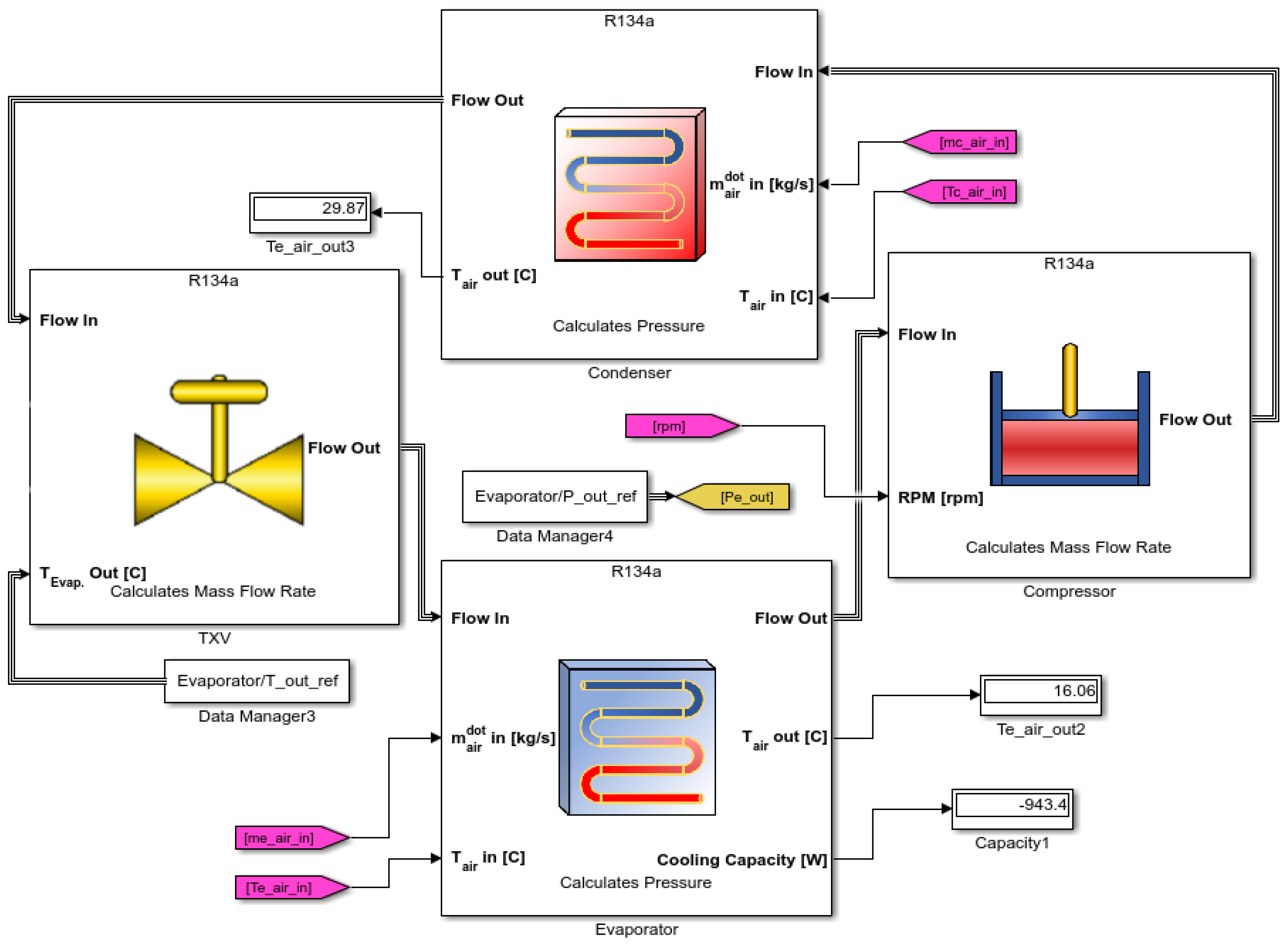
Figure 1 shows the Matlab-Simulink model implemented for a VCRS. The implemented system has the option of varying the compressor speed and the opening of the electronic expansion valve (EEV). The aim of being able to have these two actions in the system is to perform an analysis of parameters as a function of these two variables. Table 1 shows the system and material characteristics of the complete VCRS components. The analysis was performed for four heat loads, for a compressor speed range 1000–3000 rpm and the valve actuation was based on the percentage of valve opening, i.e., 0.035–0.15%. The ranges of the performance variables are those allowed by the dimensions of the VCRS.
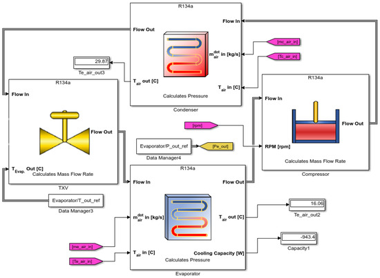
Figure 1.
Elements of Matlab-Simulink model for a vapor compression refrigeration system, from left to right, the compressor, the condenser, the expansion valve and the evaporator, respectively, with variation in the opening of the electronic expansion valve and the speed of the compressor.

Table 1.
Geometric and material characteristics of the condenser chamber components (input data to the dynamic model) [16].
3. Thermodynamic Analysis of the VCRS Cycle
In a refrigeration system, the goal is to maintain a cold zone at a temperature lower than room temperature. To achieve this, the refrigerator performs work on the system, allowing heat to be transferred from inside the refrigerator to the external environment, against the natural temperature gradient. The first law of thermodynamics efficiency for a refrigeration system refers to the ratio of the work done to the heat energy removed from the refrigerated space. In other words, it measures how efficiently the refrigerator can transfer heat from the space it wants to cool to another place, using work as input. In our case, the first law efficiency is calculated by the following equation:
where is the superheat temperature in the evaporator and is the condenser inlet temperature. Furthermore, the Coefficient of Performance (COP) is another important measurement in refrigeration systems and heat pumps. It indicates the efficiency of the system in transferring heat from a colder place to a warmer one or vice versa. The COP is computed as the ratio between the amount of heat transferred and the amount of work done in the process. This means that it is a measure of how much heat can be transferred per unit of work invested. For a refrigeration system like the one presented in this investigation, the COP is expressed as follows:
with is the cooling capacity of the system, is the refrigerant mass flow and and are the enthalpies at the inlet of the condenser and outlet of the evaporator, respectively. It is important to note that first law efficiency does not consider heat losses due to friction, conduction, and other factors within refrigeration system components.
For a complete evaluation of the performance of a refrigeration system, the efficiency of the second law of thermodynamics is also often used, which takes into account the irreversible energy losses due to the difference in temperature between the system and its surroundings. The role of the second law analysis of a refrigeration system is to determine the relation between the useful work produced and the thermal energy absorbed. This is done by identifying the locations with the highest exergy destruction, and the components with the lowest exergy or second law efficiency. The energy destruction in a component can be determined directly from an exergy balance or indirectly by first calculating the entropy generation and then using the relation
where is the ambient temperature (the dead state). For a refrigerator, is usually the temperature of the medium to high temperature (for a heat pump, it is ). The exergy destructions and exergy or second-law efficiencies for the major components of a refrigeration system operating in the cycle shown in Figure 1 can be written as follows [40]
Finally, the general exergetic efficiency is defined as
with as the sum of all element contribution of exergy, i.e., .
4. Results
4.1. VCRS Operational Parameters as a Function of Actuation Variables
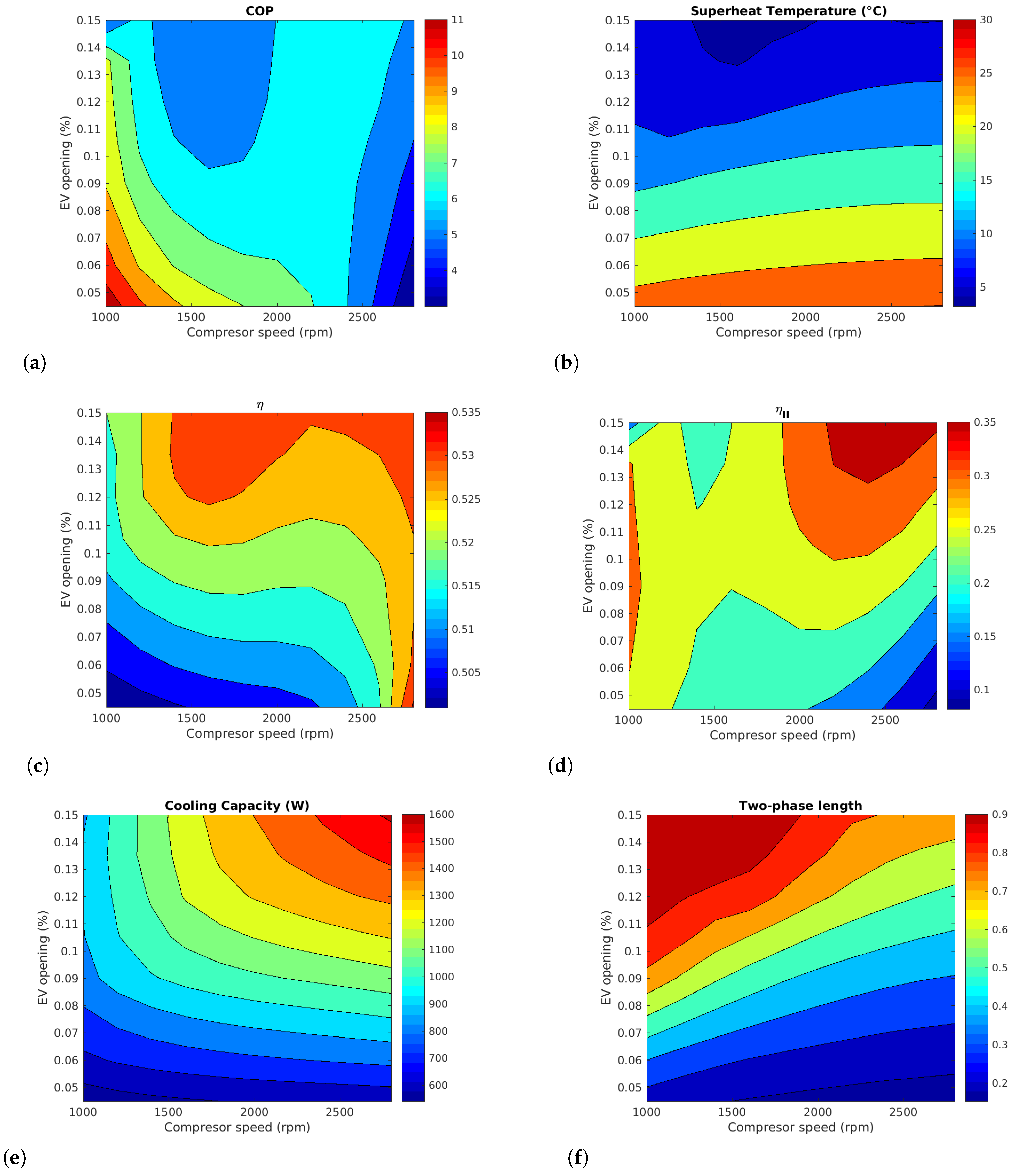
Figure 2a shows contour maps of the coefficient of performance (COP), superheat temperature, first-law efficiency (), second-law efficiency (), cooling capacity (CC), and two-phase length () as functions of the actuation parameters, compressor speed, and electronic expansion valve (EEV) opening. It can be observed that the region with the highest COP corresponds to the lowest first-law efficiency. This has significant implications for improving the overall efficiency of the VCRS, as merely increasing the COP is insufficient to enhance the system’s operation. Instead, an appropriate balance between first-law efficiency and COP must be achieved. This conclusion has already been reported in the literature, suggesting that the best approach would be to use an exergy analysis to measure the energy truly utilized for the VCRS operation [41].
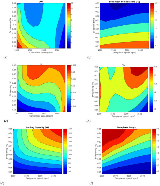
Figure 2.
Contour maps of coefficient of performance, first-law efficiency, superheat temperature, second-law efficiency, cool capacity and two-phase length as functions of compressor speed and EEV opening.
Furthermore, the COP increases as the expansion valve opening decreases due to the reduction in refrigerant mass flow (see Equation (2)), leading to an increase in refrigerant superheat temperature, as shown in Figure 2b). It is also demonstrated that the superheat temperature is mostly independent of the compressor speed, making this parameter an inverse function solely of the valve opening.
Figure 2c shows the first-law efficiency as a function of compressor speed and EEV opening. A predominant area of high efficiency, greater than 0.53, appears at a compressor speed of 1500 rpm but is bounded by a valve opening range of 0.12–0.15%. When the valve opening increases, the system can absorb more heat, increasing cooling capacity. In this context, efficiency improvement refers to the fact that more cooling output (heat absorption) is achieved with the same input energy when the EEV opening increases. From this contour map, it is shown that high compressor speed and opening valve improve the first-law efficiency; however, it is also possible to bring the system to those high-efficiency zone at a lower compressor speed (1500–2000 rpm) by choosing the EEV opening adequately.
The contour plot of the second-law efficiency is plotted in Figure 2d). The maximum efficiency is achieved at a high compressor speed, above 2200 rpm, and a large valve opening, around 0.13% or greater. Conversely, the minimum second-law efficiency is achieved at a high compressor speed but with a narrow valve opening. This effect may be because when the compressor speed increases, the refrigerant is compressed more rapidly, leading to higher pressure in the system. This improves heat transfer in the condenser and evaporator coils, increasing exergy. Additionally, a faster compressor speed also reduces the refrigerant residence time in the evaporator and condenser, potentially reducing exergy destruction.
The influence of compressor speed and EEV opening on the cooling capacity is shown in Figure 2e). It should be noted that the maximum cooling capacity zone coincides with the operating conditions of the zone of greatest second-law efficiency. This contour map provides additional information since it can be seen the possibility to keep the compressor speed and only change the EEV opening to increase the cooling capacity and viceversa. Figure 2f) is the contour plot of the two-phase length in the evaporator coil. The maximum two-phase length is achieved at compressor speed lower than 2000 rpm but at valve opening larger than 0.11% stroke. As can be observed, it is possible to change significantly the two-phase length by varying the compressor speed and EEV opening, showing that this variable could be used as a control parameter to bring the system to the high-efficiency operating zones shown in Figure 2c,d.
The behavior of the two-phase length shows a linear dependence on the valve opening, similar to that seen above in the superheat temperature. From the contour maps, it is possible to conclude that it is not sufficient to seek to lengthen the two-phase length of the evaporator to maximize efficiency or COP, as the operating region where the two-phase length is close to one is not the region of maximum efficiency and maximum COP. However, if the aim is to ensure that efficiency is always maximized from the two selected actions, a control system can be proposed where the two-phase length is always in the zone of greatest efficiency for a moderate compressor speed. From a physical point of view, this is the region where there is a good compromise between heat transfer in the evaporator and the cooling capacity of the VCRS.
4.2. VCRS Operational Parameters as a Function of Control Variables
Figure 3 presents contour maps illustrating the coefficient of performance, cooling capacity, first-law efficiency, and second-law efficiency as functions of two control parameters: superheat temperature and two-phase length. Figure 3a) demonstrates the impact of these control parameters on the coefficient of performance (COP). Notably, the COP values predominantly align with those commonly reported in VCRS literature, falling within the range between 6 and 8 [1,8,14,16].
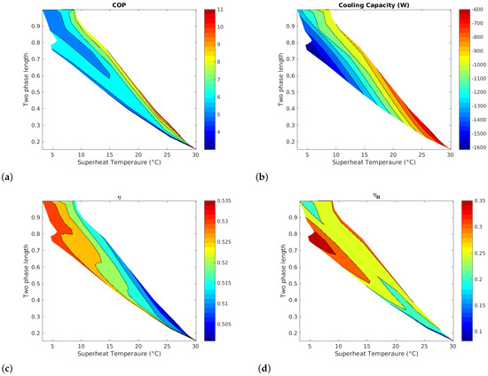
Figure 3.
Contour maps of coefficient of performance, first-law efficiency, cool capacity and second-law efficiency as functions of super heat temperature and two phase length.
In Figure 3b, a zone emerges where the cooling capacity reaches higher values. This zone is characterized by moderate two-phase lengths (0.8 to 0.9) and superheat temperatures ranging from 5 to 10 °C. Importantly, achieving a large is not necessary for attaining greater cooling capacity, which also implies a moderate EEV opening, as discussed in Section 4.1.
The reason why a larger is not necessarily favorable for the system is that it could increase the pressure drop. As increases, the refrigerant spends more time in this zone, resulting in greater flow resistance. Higher pressure drop can force the compressor to work harder to maintain refrigerant flow, thereby reducing cycle efficiency and increasing energy consumption. Consequently, it is not necessary to achieve very large values if adequate heat transfer rates can be attained with reasonable values. While increasing the two-phase length could allow for more heat absorption, this must be balanced against the efficiency of heat transfer in the condensing stage. Conversely, increasing the superheat temperature could negatively affect the compressor’s operation. This can lead to increased compressor heating, potentially impacting its performance and lifetime.
Figure 3c presents the first-law efficiency contour map as a function of the control parameters. The maximum efficiency is observed at moderate superheat temperatures, approximately below 10 °C, and large values of . In terms of first-law efficiency, a larger two-phase length enhances heat transfer in the evaporator, allowing the system to provide more cooling effect for a given input energy. However, while a larger two-phase length can improve first-law efficiency, an excessively long two-phase region might lead to inadequate vaporization and operational issues in the compressor.
In Figure 3d, the second-law efficiency contour map is plotted as a function of control parameters. As for the cooling capacity, these results clearly show that excessive two-phase length in the evaporator can have unfavorable effects on the exergy, collapsing second-law efficiency values in a smaller area, in contrast with first-law efficiency.
4.3. VCRS Model for Control Design
The control design was performed using the seven states evaporator model presented in [38], although extracting only the subsystem composed by the two-phase length and superheat temperature dynamics. The following representation is obtained:
where
and , ; note that the control inputs, u, are the compressor velocity and the valve stroke, which in turn define the corresponding flow rates as in the model proposed in [38], for further details see Appendix A.
Note that Equation (10) represents a fully actuated system subject to both, multiplicative and additive perturbations. The additive perturbations primarily arise from the dynamics of the original higher-dimensional system and from uncertainty in the time-varying parameters. Conversely, the multiplicative perturbations stem from the time-varying nature of parameters in .
4.4. MIMO Sliding Mode Control for a VCRS
This section presents the proposed control for a VCRS. The control task is to steer the superheat temperature and the two-phase length to some specific operation points selected based on the contour maps previously presented. Such a selection is made for energy-saving purposes and is aimed to bring the system inside high-efficiency operation regions. A MIMO control is designed based on a nominal linear model obtained from Equations (9) and (10). The control consist of a feedforward term for a nominal operation condition plus sliding mode control. The nominal model is obtained by evaluating the parameters on and for a steady-state operating point. Hence, the sliding mode term is aimed at rejecting perturbations and, upon requirement, to achieve the desired operation set points. The following controller is proposed
where is a constant vector corresponding to a feedforward term, , and . The subscript d stands for desired reference values and N for nominal . The steady-state for computation of is obtained using only , K is set to zero. Note that for any operation point different from the nominal one we have
due to the deviation from that point. For constant desired references the error dynamics can be written as
According to the results in [32], the following Assumptions are sufficient in order to ensure that convergence can be enforced by a proper selection of the gain K. Let and be defined as follows
- Assumption 1. is nonsingular and such that .
- Assumption 2. .
Such assumptions were verified on simulation for the case of study presented in next section. Finally, it is well-known that classical sliding mode control may lead to high-frequency vibration so-called chattering. A first-order filter is introduced for chattering attenuation [42]. The time constant of this filter is related to the dynamics of the compressor and the EEV.
4.5. Simulation Results
The steady-state corresponding to apply only the constant vector input in Equation (12) lead to the nominal steady-state operation point with the following
From simulations data for a transient in superheat temperature from to , we have that Assumption 1 and 2 stated in the previous section holds for the forthcoming study cases. Hence, the controller presented in Equation (12) is applied using . The results are presented in this section.
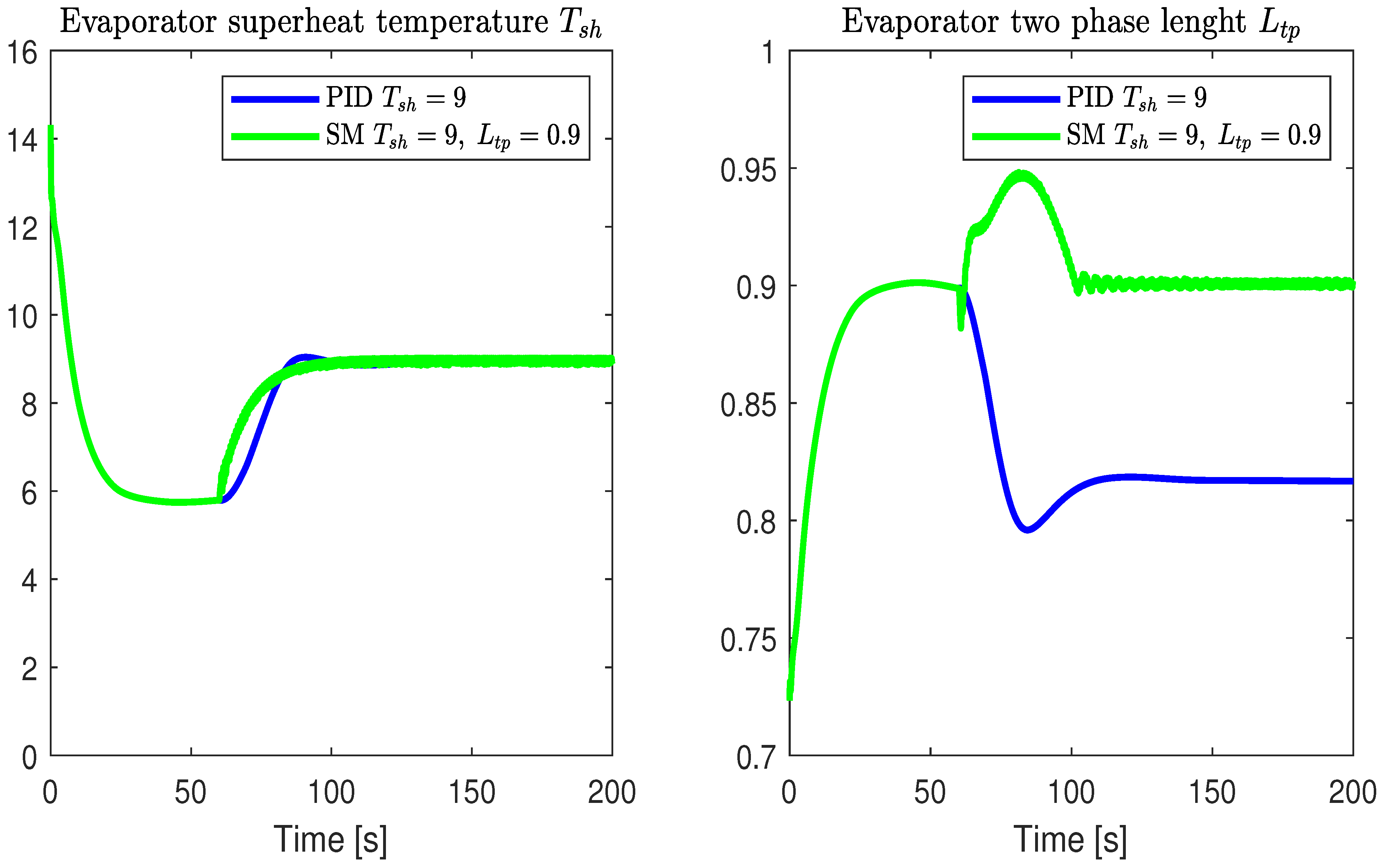
As a first test, a PID controller that uses EEV stroke to control while preserving a constant compressor velocity is compared against the proposed sliding mode controller which considers compressor velocity as control input and two-phase length as controlled output. The results are shown in Figure 4 and Figure 5. The desired superheat temperature is while for the sliding mode controller, there is also a desired two-phase length corresponding to a . Due to large overshoot when introducing a large step change on superheat temperature, this step is smoothed by a first-order filter with time constant of 10 s. From Figure 4, it is clear that when controlling both, superheat temperature and two-phase length, a reduction in compressor velocity is achieved while maintaining the superheat temperature, see Figure 5.
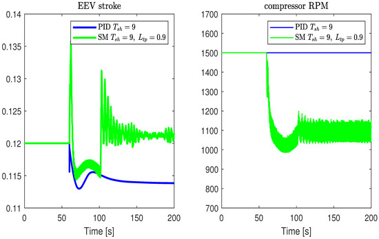
Figure 4.
EEV opening fraction and compressor speed.

Figure 5.
Evaporator two-phase length and superheat temperature.
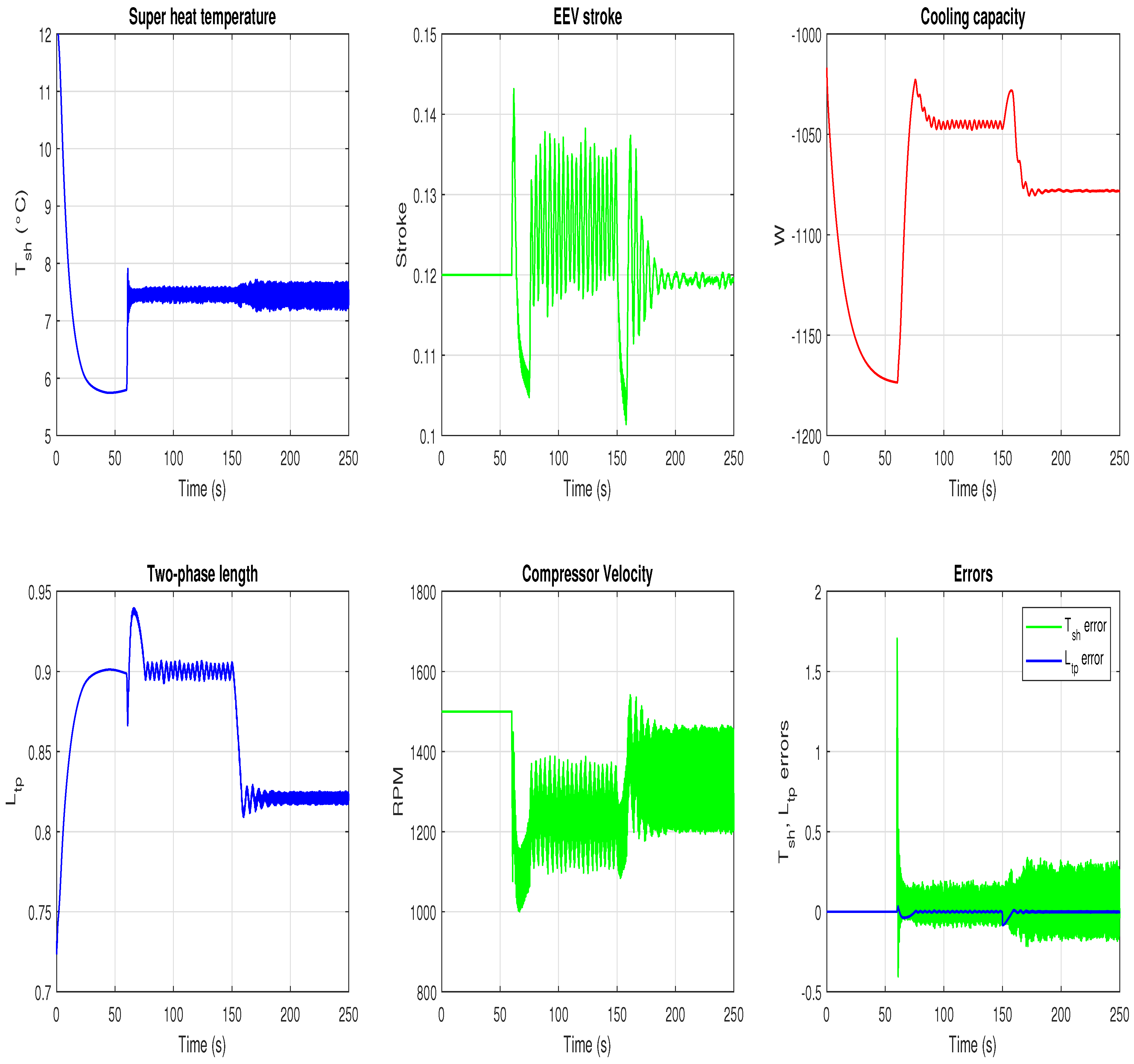
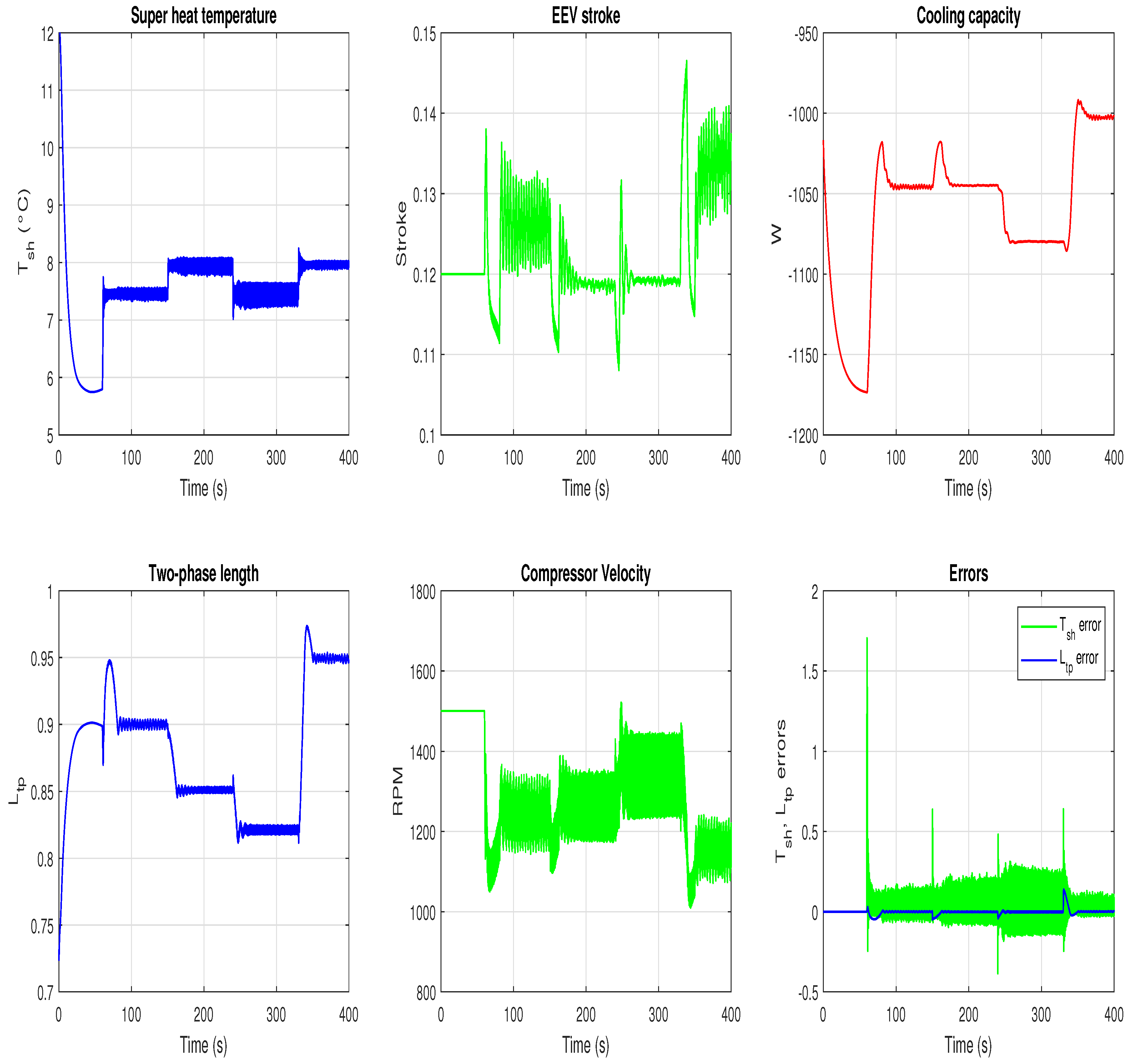
Additionally, some operating conditions were selected to steer the system towards operation regions of good efficiency concerning the contour maps presented in Section 4. Figure 6 shows a change in both, two-phase length and superheat temperature which change from and , respectively, and 8 while preserving the cooling capacity, in order to highlight the possibility of different selections for those variables leading to the same cooling capacity. Each one of the Figure 6, Figure 7, Figure 8 and Figure 9 contain six plots corresponding to: The two control inputs, the two controlled outputs, the cooling capacity, and the last one for the output errors.
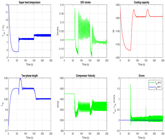
Figure 6.
Operation point change preserving cooling capacity.
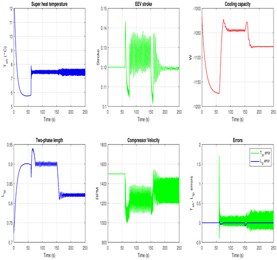
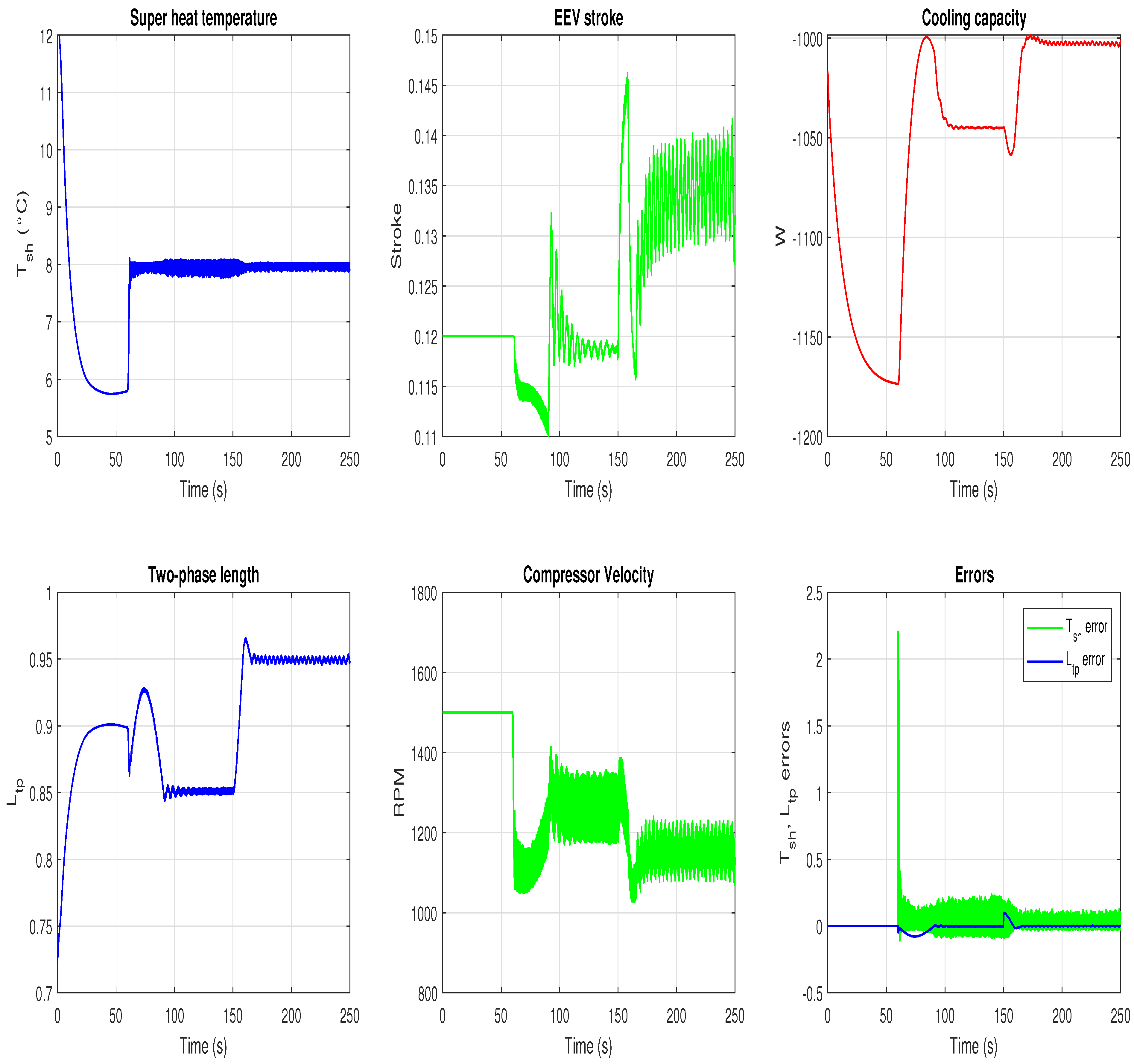
Figure 7.
Increasing cooling capacity.

Figure 8.
Decreasing cooling capacity.
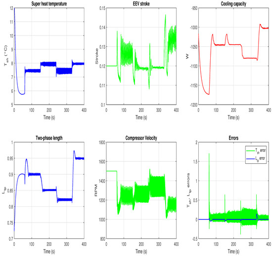
Figure 9.
Switching among several operation configurations.
In Figure 7, there is a reduction in two-phase length from 0.9 to 0.82 without change in . As a consequence, the cooling capacity is increased. Note that the controller increases the compressor velocity. That behavior illustrates the complexity of the interactions in the system since for the same a larger does not necessarily lead to a larger cooling capacity.
Figure 8 shows the inverse scenario to the one in Figure 7; however, a rather large is obtained after 150 s. As a result, there is a reduction in compressor velocity and cooling capacity, showing the possibility of using these variables to adjust the operating point depending on the thermal load.
Finally, in Figure 9 all the previous cases are shown in order to show that the switching between the different operating points can be achieved with one single controller. This is an appealing advantage of the proposed scheme in contrast with classical controllers such as PID which must be tuned for the specific operating region to avoid performance degradation or failure in achieving the control objective.
In practice, the control system can bring the VCRS to a wide range of operating conditions, highlighting the high-efficiency zones and adjusting the compressor speed and EEV opening based on the cooling capacity required for the thermal load. For instance, if cooling capacity must be increased, the control will bring the VCRS to a zone where that capacity can be achieved by changing not only the compressor speed but also the EEV opening within the high-efficiency zone. This approach can represent significant energy savings for the system, given that the main source of consumption is the compressor and its power demand is directly proportional to its speed. The proposed controller involves using a variable speed compressor and an EEV. Variable speed compressors have been introduced in new domestic and commercial refrigeration technologies, gradually becoming a standard for energy saving. EEVs have traditionally been used in refrigeration chambers; however, inexpensive versions of these valves are now available, allowing their incorporation into smaller refrigeration systems. From the hardware perspective required for control implementation, the selected sliding mode control does not demand high processing power, ensuring that its implementation is not expensive compared to more advanced types of control.
5. Concluding Remarks
A comprehensive parametric investigation was conducted to analyze the performance of a refrigeration system under varying compressor speed and electronic expansion valve (EEV) openings. An analysis based on the first and second laws of thermodynamics was performed, enabling the identification of optimal system performance conditions. Special attention was paid to the behavior of the evaporator’s two-phase length and superheat temperature as functions of these system variations. The main contribution and findings of this investigation can be summarized as:
- The study revealed through parametric analysis that the combined manipulation of compressor speed and EEV opening allows the system to be brought to operating regions favorable for optimal two-phase length and cooling capacity.
- It is demonstrated that merely seeking to maximize the two-phase length is insufficient for optimizing the system’s efficiency or COP. Rather, it was found that the operating region where higher efficiency is achieved corresponds to a two-phase length between 0.7 and 0.9.
- A control system based on the two-phase length and the superheat temperature was proposed to bring the system to the high-efficiency operating points found through the performed parametric analysis. Different scenarios were used to evaluate the behavior of the control system.
- The control system can be used to adjust the compressor speed based on the cooling capacity requirements of the VCRS. For instance, in the case presented in Figure 8, the cooling capacity of the system can be reduced, representing a decrease in compressor speed of approximately 11.5%. This reduction directly translates to energy savings for the system.
- It was found that controlling the evaporator’s two-phase length and the superheat temperature makes it possible to reduce the compressor speed maintaining the cooling capacity. To the best of the author’s knowledge, this is the first investigation in which a control for a refrigeration system is based on the two-phase length of the evaporator.
The study presented aimed to show the advantages of the proposed MIMO control scheme. Nevertheless, a further analysis remains open for future work regarding different control strategies that can achieve high performance with relatively low computational load and ensuring that the actuators operating demands are feasible, preventing actuators from fast wearing.
Author Contributions
Conceptualization, A.E., L.C.-C. and S.P.; methodology, A.E., L.C.-C. and S.P.; software, A.E., L.C.-C. and S.P.; validation, A.E. and L.C.-C.; formal analysis, A.E., L.C.-C. and S.P.; investigation, A.E., L.C.-C. and S.P.; data curation, A.E. and L.C.-C.; writing—original draft preparation, A.E., L.C.-C. and S.P.; writing—review and editing, A.E. and S.P.; visualization, A.E. and L.C.-C.; supervision, S.P.; project administration, S.P. All authors have read and agreed to the published version of the manuscript.
Funding
Publication of this research was funded through CONAHCYT’s project No. 322615—“F003 Desarrollo de tecnología incremental y disruptiva en sistemas de enfriamiento 2023–2024”.
Data Availability Statement
The data presented in this study are available from the corresponding author upon reasonable request.
Acknowledgments
The authors acknowdledge support from CONAHCYT’s project No. 321159 “Laboratorio Nacional de Investigación en Tecnologías del Frío”. A. Estrada and S. Piedra thank the “Investigadoras e Investigadores por México” program from CONAHCYT.
Conflicts of Interest
The authors declare no conflicts of interest. The funding sponsors had no role in the design of the study; in the collection, analyses, or interpretation of data; in the writing of the manuscript, and in the decision to publish the results.
Nomenclature
The following terms are used in this manuscript:
| Superheat temperature in the evaporator | |
| Condenser inlet temperature | |
| Enthalpy at the inlet of the condenser | |
| Enthalpy at the outlet of the evaporator | |
| Cooling capacity of the system | |
| Refrigerant mass flow | |
| Exergy destruction in compressor | |
| Exergy destruction in condenser | |
| Exergy destruction in valve | |
| Exergy destruction in evaporator | |
| Entropy generated | |
| Energy flux to high temperature medium | |
| High temperature medium | |
| Energy flux to low temperature medium | |
| Low temperature medium | |
| First law efficiency | |
| Second law efficiency | |
| Supplied energy | |
| COP | Coefficient of Performance |
Appendix A
- = Specific heat at constant pressure of vapor refrigerant,
- = Refrigerant mass flow rate at point 4,
- = Refrigerant vapor quality at point 4,
- = Enthalpy of liquid refrigerant,
- = Mass flow rate of liquid refrigerant,
- = Convection heat transfer coefficient of refrigerant,
- = Evaporator heat exchanger area,
- = Evaporator flow length,
- = Enthalpy of the refrigerant vapor in saturation,
- = Enthalpy of liquid refrigerant at saturation,
- = Two phase length in the evaporato,
- = Refrigerant volume in the evaporator,
- = Vapor refrigerant density,
- = Density of liquid refrigerant at point 4,
- = Initial temperature,
- = Temperature at point 1,
- = Temperature of the working fluid in the evaporator at the saturation point of the pipe.
References
- Sleiti, A.K.; Al-Ammari, W.A.; Al-Khawaja, M. Review of innovative approaches of thermo-mechanical refrigeration systems using low grade heat. Int. J. Energy Res. 2020, 44, 9808–9838. [Google Scholar] [CrossRef]
- Cohen, R.; Hamilton, J.; Pearson, J. Possible Energy Conservation through Use of Variable Capacity Compressors. In Proceedings of the International Compressor Engineering Conference 1974, West Lafayette, IN, USA, 10–14 July 1974. [Google Scholar]
- Binneberg, P.; Kraus, E.; Quack, H. Reduction in Power Consumption of Household Refrigerators by Using Variable Speed Compressors. In Proceedings of the International Refrigeration and Air Conditioning Conference 2002, West Lafayette, IN, USA, 16–19 July 2002. [Google Scholar]
- Khatri, R.; Joshi, A. Energy performance comparison of inverter based variable refrigerant flow unitary AC with constant volume unitary AC. Energy Procedia 2017, 109, 18–26. [Google Scholar] [CrossRef]
- Schibuola, L.; Scarpa, M.; Tambani, C. Variable speed drive (VSD) technology applied to HVAC systems for energy saving: An experimental investigation. Energy Procedia 2018, 148, 806–813. [Google Scholar] [CrossRef]
- Liu, C.; Sang, C.; Li, G.; Li, W.; Ning, B.; Zhu, J.; Guo, Y.; Li, T. Experimental investigation on the influence of electronic expansion valve opening on the performance of miniature refrigeration system. Appl. Therm. Eng. 2024, 248, 123287. [Google Scholar] [CrossRef]
- Li, H.; Su, Z.; Zhao, C.; An, T.; Qin, X.; Chen, G.; Gao, J.; Zhang, Y. Influence of compressor speed on the performance of low pressure vapor-injected refrigeration systems. Therm. Sci. 2024, 28, 2043–2049. [Google Scholar] [CrossRef]
- Al-Hassani, A.H.; Al-Badri, A.R. Effects of compressor speed and electronic expansion valve opening on the performance of R410a water chiller system. Wasit J. Eng. Sci. 2020, 8, 12–20. [Google Scholar] [CrossRef]
- Nunes, T.; Vargas, J.; Ordonez, J.; Shah, D.; Martinho, L. Modeling, simulation and optimization of a vapor compression refrigeration system dynamic and steady state response. Appl. Energy 2015, 158, 540–555. [Google Scholar] [CrossRef]
- Roy, R.; Emani, M.S.; Mandal, B.K. Numerical simulation of vapour compression refrigeration system using refrigerant R152a, R404a and R600a. Indian J. Sci. Res. 2017, 15, 62–67. [Google Scholar]
- Catano, J.; Zhang, T.; Wen, J.T.; Jensen, M.K.; Peles, Y. Vapor compression refrigeration cycle for electronics cooling–Part I: Dynamic modeling and experimental validation. Int. J. Heat Mass Transf. 2013, 66, 911–921. [Google Scholar] [CrossRef]
- Chi, J.; Didion, D. A simulation model of the transient performance of a heat pump. Int. J. Refrig. 1982, 5, 176–184. [Google Scholar] [CrossRef]
- Jankovic, Z.; Pavkovic, B.; Sieres, J.; Zivic, M. Compressor Speed, Expansion Valve Opening and Refrigerant Charge Influences on the Propane Unit Design. In Proceedings of the International Refrigeration and Air Conditioning Conference 2022, West Lafayette, IN, USA, 10–14 July 2022. [Google Scholar]
- Koury, R.; Machado, L.; Ismail, K. Numerical simulation of a variable speed refrigeration system. Int. J. Refrig. 2001, 24, 192–200. [Google Scholar] [CrossRef]
- Tu, Q.; Zhang, L.; Cai, W.; Guo, X.; Yuan, X.; Deng, C.; Zhang, J. Control strategy of compressor and sub-cooler in variable refrigerant flow air conditioning system for high EER and comfortable indoor environment. Appl. Therm. Eng. 2018, 141, 215–225. [Google Scholar] [CrossRef]
- Rasmussen, B.P.; Alleyne, A.G. Dynamic Modeling and Advanced Control of Air Conditioning and Refrigeration Systems; Air Conditioning and Refrigeration Center TR-244; University of Illinois: Urbana, IL, USA, 2006. [Google Scholar]
- Xia, Y.; Du, J.; Deng, S. Effects of superheat nonlinearity on the operational stability of a direct expansion (DX) air conditioning (A/C) system. Energy Procedia 2017, 142, 1854–1859. [Google Scholar] [CrossRef]
- Schurt, L.C.; Hermes, C.J.; Neto, A.T. A model-driven multivariable controller for vapor compression refrigeration systems. Int. J. Refrig. 2009, 32, 1672–1682. [Google Scholar] [CrossRef]
- Yang, Z.; Pollock, D.T.; Wen, J.T. Optimization and predictive control of a vapor compression cycle under transient pulse heat load. Int. J. Refrig. 2017, 75, 14–25. [Google Scholar] [CrossRef]
- Yin, X.; Li, S. Model Predictive Control for Vapor Compression Refrigeration Cycle Process. Int. J. Autom. Comput. 2015. [Google Scholar] [CrossRef]
- Li, H.; Jeong, S.K.; You, S.S. Feedforward control of capacity and superheat for a variable speed refrigeration system. Appl. Therm. Eng. 2009, 29, 1067–1074. [Google Scholar] [CrossRef]
- Jain, N.; Alleyne, A.G. Comparison of SISO and MIMO control techniques for a diagonally dominant vapor compression system. In Proceedings of the 2009 American Control Conference, St. Louis, MI, USA, 10–12 June 2009; pp. 1580–1585. [Google Scholar] [CrossRef]
- Bejarano, G.; Alfaya, J.A.; Ortega, M.G.; Rubio, F.R. Multivariable analysis and H∞ control of a one-stage refrigeration cycle. Appl. Therm. Eng. 2015, 91, 1156–1167. [Google Scholar] [CrossRef]
- Alfaya, J.A.; Bejarano, G.; Ortega, M.G.; Rubio, F.R. Controllability analysis and robust control of a one-stage refrigeration system. Eur. J. Control 2015, 26, 53–62. [Google Scholar] [CrossRef]
- Kim, J.G.; Han, C.H.; Jeong, S.K. Disturbance observer-based robust control against model uncertainty and disturbance for a variable speed refrigeration system. Int. J. Refrig. 2020, 116, 49–58. [Google Scholar] [CrossRef]
- Goyal, A.; Staedter, M.A.; Garimella, S. A review of control methodologies for vapor compression and absorption heat pumps. Int. J. Refrig. 2019, 97, 1–20. [Google Scholar] [CrossRef]
- Ding, T.L.; Norris, S.; Subiantoro, A. Adaptive Reinforcement Learning PI Controllers for Vapor Compression Cycle Control. In Proceedings of the 19th International Refrigeration and Air Conditioning Conference, Purdue, West Lafayette, IN, USA, 10–14 July 2022. [Google Scholar]
- Christian Rosdahl, B.B.; Eisenhower, B. Model-free MIMO control tuning of a chiller process using reinforcement learning. Sci. Technol. Built Environ. 2023, 29, 782–794. [Google Scholar] [CrossRef]
- Huang, Y.; Khajepour, A.; Ding, H.; Bagheri, F.; Bahrami, M. An energy-saving set-point optimizer with a sliding mode controller for automotive air-conditioning/refrigeration systems. Appl. Energy 2017, 188, 576–585. [Google Scholar] [CrossRef]
- Jackson, S.D.; Palazotto, A.N.; Pachter, M.; Niedbalski, N. Control of Vapor Compression Cycles under Transient Thermal Loads. In Proceedings of the AIAA Scitech 2019 Forum, Online, 7–11 January 2019. [Google Scholar] [CrossRef]
- Utkin, V.I.; Guldner, J.; Shi, J. Sliding Mode Control in Electromechanical Systems; Automation and Control Engineering Series; Taylor & Francis: Abingdon, UK, 2009. [Google Scholar]
- Bejarano-Rincón, A.; Estrada, A.; Herrera-Hernández, E.; Alvarado-Orozco, J. Control design for a class of multivariable nonlinear system with uncertain control direction: A laser cladding case study. Eur. J. Control 2021, 60, 114–124. [Google Scholar] [CrossRef]
- Rubagotti, M.; Incremona, G.P.; Ferrara, A. A Discrete-Time Integral Sliding Mode Control Law for Systems With Matched and Unmatched Disturbances. IEEE Control Syst. Lett. 2024, 8, 448–453. [Google Scholar] [CrossRef]
- Ekren, O.; Sahin, S.; Isler, Y. Comparison of different controllers for variable speed compressor and electronic expansion valve. Int. J. Refrig. 2010, 33, 1161–1168. [Google Scholar] [CrossRef]
- Li, B.; Peuker, S.; Hrnjak, P.S.; Alleyne, A.G. Refrigerant mass migration modeling and simulation for air conditioning systems. Appl. Therm. Eng. 2011, 31, 1770–1779. [Google Scholar] [CrossRef]
- Pangborn, H.; Alleyne, A.G.; Wu, N. A comparison between finite volume and switched moving boundary approaches for dynamic vapor compression system modeling. Int. J. Refrig. 2015, 53, 101–114. [Google Scholar] [CrossRef]
- Wallace, M.; McBride, R.; Aumi, S.; Mhaskar, P.; House, J.; Salsbury, T. Energy efficient model predictive building temperature control. Chem. Eng. Sci. 2012, 69, 45–58. [Google Scholar] [CrossRef]
- Yao, Y.; Wang, W.; Huang, M. A state-space dynamic model for vapor compression refrigeration system based on moving-boundary formulation. Int. J. Refrig. 2015, 60, 174–189. [Google Scholar] [CrossRef]
- Qiao, H.; Laughman, C.R.; Aute, V.; Radermacher, R. An advanced switching moving boundary heat exchanger model with pressure drop. Int. J. Refrig. 2016, 65, 154–171. [Google Scholar] [CrossRef]
- Cengel, Y. Solucionario termodinámica (vol. 7ma edicion); McGraw Hill: Mexico City, Mexico, 2012. [Google Scholar]
- Solanki, N.; Arora, A.; Singh, R. Performance enhancement and environmental analysis of vapor compression refrigeration system with dedicated mechanical subcooling. Int. J. Air-Cond. Refrig. 2023, 31, 26. [Google Scholar] [CrossRef]
- Utkin, V.; Lee, H. Chattering problem in sliding mode control systems. IFAC Proc. Vol. 2006, 39, 1. [Google Scholar] [CrossRef]


Disclaimer/Publisher’s Note: The statements, opinions and data contained in all publications are solely those of the individual author(s) and contributor(s) and not of MDPI and/or the editor(s). MDPI and/or the editor(s) disclaim responsibility for any injury to people or property resulting from any ideas, methods, instructions or products referred to in the content. |
© 2024 by the authors. Licensee MDPI, Basel, Switzerland. This article is an open access article distributed under the terms and conditions of the Creative Commons Attribution (CC BY) license (https://creativecommons.org/licenses/by/4.0/).