Article

Numerical Simulation Study of Combustion under Different Excess Air Factors in a Flow Pulverized Coal Burner

1
State Grid Xinjiang Economic Research Institute, Urumqi 830063, China
2
Laboratory of Energy Carbon Neutrality, School of Electrical Engineering, Xinjiang University, Urumqi 830047, China
3
Center of New Energy Research, School of Future Technology, Xinjiang University, Urumqi 830047, China
4
Engineering Research Center of Northwest Energy Carbon Neutrality, Ministry of Education, Urumqi 830017, China
*
Author to whom correspondence should be addressed.
Processes 2024, 12(8), 1607; https://doi.org/10.3390/pr12081607
Submission received: 13 June 2024 / Revised: 27 July 2024 / Accepted: 29 July 2024 / Published: 31 July 2024
(This article belongs to the Section Chemical Processes and Systems)

Abstract

:
The basic national condition that is dominated by coal will not alter in the foreseeable future. Coal-fired boiler is the main equipment for coal utilization, and cyclone burner is a practical type of burner. There is a cyclone formation, a primary air duct inside the center air duct, and a secondary air duct. Introducing a small stream of pulverized coal gas or oil mist stream or gas directly into the reflux zone in the center duct ignites first a stable combustion and a small fluctuation of ignition pressure. In this paper, the variation of furnace temperature for cyclone pulverized coal burner corresponding to different excess air factors and the composition of gases such as O2, CO, CO2, and NOX produced by combustion were investigated using fluent software. A single cyclone pulverized coal burner from an actual coal-fired boiler is used, and a combustion zone applicable to the study of a single pulverized coal burner is established to study the actual operation of a single pulverized coal burner at different excess air coefficients. The findings indicate that the ignition position of pulverized coal combustion advances with decreasing α (Excess Air Factors); however, the length of the produced high-temperature flame gets shorter. As the value of α decreases, the burnout in the furnace decreases and the CO emission concentration increases, with a maximum CO mole fraction of 0.38% at α = 1.2 and a maximum CO mole fraction of 3.13% at the axial position when α decreases to 0.8. The furnace’s concentration of NOX, the NOX emission level decreases significantly with decreasing α. The NOX mole mass increases gradually with increasing α, and in the bottom portion of the primary combustion zone, more NOX is produced. The concentration of NOX in the chamber changes significantly after α exceeds 1.0, and the NOX at the outlet surges from 417.25 ppm to 801.07 ppm, which is attributed to the increase in the average temperature of the chamber, which promotes the generation of thermophilic NOX. The distribution pattern of O2 mole fraction along the furnace height cross-section at different excess air factors is basically the same, with a maximum at the burner inlet and a gradual decrease in the O2 content as it enters the combustion chamber to react with the pulverized coal in a combustion reaction. The value of α = 0.8 when the air supply is obviously insufficient, the fuel cannot be fully combusted, and only a small amount of CO2 is produced.

1. Introduction

During the 75th session of the UN General Assembly on 22 September 2020, General Secretary Xi suggested that nationally owned contributions will be increased, stronger laws and regulations will be enacted, and efforts will be made to peak carbon dioxide emissions by 2030. Make it a goal to become carbon neutral by 2060, promote the “green recovery” of the world economy in the aftermath of the pandemic, and build up a strong synergy for sustainable development [1]. Approximately 75% of China’s entire consumption of energy is generated by coal. It is the top producer and user of the fuel worldwide, and about 84% of its coal production is directly used for combustion, resulting in serious soot-type air pollution [2]. The Air Pollution Prevention and Control Act [3] clearly states that air pollution from coal combustion should be prevented by implementing technologies such as coal washing and processing, sulfur-fixing coal [4], constructing desulfurization and dust removal devices [5], as well as by implementing a system of levying sewage charges according to the types and quantities of pollutants discharged into the atmosphere. Pollutant emissions from coal-fired boilers [6] and the evaluation of the effects of various low-pollution combustion technologies [7] have become common concerns and put forward higher requirements for the science and rationality of boiler exhaust monitoring and analyzing technology [8]. Boiler combustion condition fluctuations [9], coal quality fluctuations or actual flue gas sampling and analysis and testing methods [10] on the problems, often easy to a variety of low-pollution combustion technologies, especially coal, clean coal additives [11], calcium spray desulfurization [12], such as in-furnace combustion desulfurization technology [13] effect of the correct evaluation of a certain error. Environmental protection and scientific research institutions have been monitoring and evaluating the combustion pollution emissions and low-pollution combustion technologies of numerous boilers. However, there are limitations on the technical means of monitoring pollution sources and a lack of people with sufficient understanding who tend to analyze the concentration of individual constituent factors such as O2, CO, CO2, NO, NOX, etc., in the flue gas in isolation and ignore the different flue gas constituents among the potential interrelationships between different flue gas components [14]. Flue gas in a variety of components of raw materials are from the combustion reaction of coal and air. The combustion process in the furnace is also with the people under strict control of the conditions, and the combustion process itself has a certain degree of regularity, so the combustion of fluctuations in the dynamic flue gas is produced by the composition of the inevitable existence of a certain relationship between the inner. Exploration of the interrelationship between different flue gas components is conducive to the development of technologies for simultaneous treatment of SOX, NOX, soot, and other pollutants; comparison of the characteristics of pollution emissions between different furnace types is conducive to the selection of economic, applicable, and efficient pollution control technologies for different furnace types, and to achieve the emission standards of pollutants under low-cost investment [15].
Many experts and scholars have studied the combustion characteristics and analyzed the effects of different working conditions on the flame temperature and pollutant emissions in the combustion chamber. In terms of numerical simulation of pulverized coal combustion, Ruipeng Cai et al. introduced some numerical methods and research progress in coal combustion modeling at this stage [16]. Prakash Ghose et al. discussed various common models widely used in PCC simulation and their modeling aspects from a scientific point of view [17]. Wajdi Rajhi et al. investigated the effect of initial pressure (IP) on catalytic methane-air combustion (CMAC) in microchannels using the molecular dynamics (MD) method [18]. Patel et al. [19] experimentally investigated the effects of equivalence ratio and cyclone blade angle on the flame appearance and pollutant emission of LPG diffusion combustion in a coaxial combustor, and the results showed that the diffusion flame length of DC jet combustion was gradually lengthened with the increase of the fuel inlet velocity, but the overall length of the flame was gradually shortened with the increase of the air inlet velocity. Zhen et al. experimentally investigated the effect of cyclone on the heat transfer behavior and showed that at the same air/fuel flow rate, the flame shapes of cyclone and DC jet combustion are similar and the reaction zone of cyclone combustion is closer to the exit end of the burner, but the diffusion flames of cyclone combustion are shorter, wider, and more stable [20].
Energy savings and emission reduction to reduce the carbon dioxide content of coal-fired power plants is an essential method for accomplishing carbon peaking and carbon neutrality goals, in which the burner is a crucial part of the safe operation of coal-fired units, saving energy and reducing consumption. The burner affects the fuel-combustion process and the pollutant emissions. This paper uses the cyclone pulverized coal burner for numerical simulation; the pulverized coal cyclone burner enables the capture of ash from the pulverized coal-combustion process. In the cyclone-combustion process, due to the reverse pressure gradient in the center axis of the combustion chamber, a central return zone and an annular chamber return are formed, which play a key role in the stable ignition of pulverized coal and the capture of ash. The cyclone pulverized coal burner is characterized by a lengthy period of residency of coal powder in the zone of elevated temperatures within the pulverized coal burner, and thus, the combustion efficiency is excellent, and the exhaust directly emits no black smoke but rather steamy white smoke. This type of pulverized coal burner has a shortened temperature rise time for heating, a high thermal efficiency, and a low requirement for the quality of coal. The coal type is suitable for a wide range of coal, with high economic efficiency. Pulverized coal burner ignition is easy, fast warming, works efficiently, and is greatly improved.
Actual air consumption in boiler operation is always greater than the theoretical air requirement. The ratio of the actual air consumption to the theoretical air requirement is called the excess air factor. For boiler hearths, the air excess factors for flue gas calculations are related to the type of combustion equipment and the type of fuel. In order to maintain good combustion, attention should be paid to controlling the excess air factor of the furnace to ensure the proper air-coal ratio in combustion. In operation, the furnace exit excess air factor is controlled by measuring the oxygen level at the exit of the tail flue. The excess air factor is the ratio of the actual air requirement to the theoretical air requirement for fuel combustion, and is expressed as “α” using the following calculation formula [21]:
α = Vk/V0
Vk: the actual amount of air supplied; V0: theoretical air volume.
In this paper, the combustion of a cyclone pulverized coal burner corresponding to different excess air factors is investigated using fluent software and separate temperature measurements for burners at different excess air factors. Several combustion conditions were simulated (α = 0.8, 0.9, 1.0, 1.1, 1.2), and the gas compositions of O2, CO, CO2, and NOX produced by combustion were analyzed. The excess air coefficients of boilers under cyclonic combustion are subdivided, and the changes in the emission relationship between each air pollutant under the combined effect of cyclonic combustion and excess air coefficients are investigated. This paper investigated the effects of different excess air coefficients on the temperature distribution, velocity distribution, and NOx generation in the combustion chamber of a boiler under cyclonic flow. In the present work, it can be further subdivided into the variation of excess air factors to find the most suitable combustion conditions and the lowest pollutant emissions. In order to achieve energy savings and emission reductions, the variation of the pollutant gas emission relationship is observed by varying the excess air factors to seek the maximum combustion efficiency to obtain the lowest nitrogen yield.
In this paper, a single cyclone pulverized coal burner from an actual coal-fired boiler is used and a combustion zone applicable to the study of a single pulverized coal burner is established to study the actual operation of a single pulverized coal burner at different excess air coefficients.

2. Simulation Objects and Methods

2.1. Geometric Modeling

In this investigation, a lone cyclone burner is employed to simulate in a hog fuel-fired boiler. The burner is simplified by removing components of the cyclone burner that do not impact its operation. The cyclone burner consists of a circular nozzle with various types of cyclone generators in the burner. The cyclone burner is arranged on the front and rear walls of the furnace and is supplied with air from a large bellows. Design the simplified burner model as a one-to-one ratio. As shown in Figure 1, this research is founded on a single cyclone pulverized coal combustion chamber with a secondary vane angle of 50° inside the combustion chamber and a secondary air vane angle of 30° outside. In order to conduct the study, a cylindrical virtual combustion area is created with 10 meters in length and 5 m in diameter (with respect with the axis of orientation). To avoid the formation of a back flow zone near the heating system’s output, the cylindrical zone of two and a half meters in length was installed near the cylindrical furnace’s outflow.

2.2. Boundary Conditions

The main burner nozzle and the combustion air nozzle both adopt velocity inlet boundary conditions; the furnace chamber outlet adopts pressure outlet boundary conditions; the pulverized coal particles are injected into the furnace chamber by the primary air nozzle, and the specific settings of the boundary conditions are shown in Table 1. The type of coal used in this study was analyzed, as shown in Table 2. The particle size distribution of the particles followed the Rosin–Rummler law, and the average particle size of the coal particle was 53 µm [22].

2.3. Numerical Simulation

Detailed simulations and models of fluid dynamics, temperature distributions, and chemical reactions within the furnace during burner operation were performed using commercial software ANSYS 2022R1 Fluent. The combustion process is simulated using an appropriate mathematical model, and it adheres to the principles of conservation of energy, conservation of mass, and conservation of momentum. The simulations were performed employing an upwind second-order-type design with a straightforward formula for the fields of pressure and velocity [23]. The vortex vanes in the combustion chamber create a flow with high vortex intensity, and to be able to achieve a precise result, the aerodynamic field near the exit of the combustion chamber was simulated using the Reynolds Stress Models (RSM). The Reynolds stress transport equation is an important equation that describes the viscous stress distribution within a fluid. In fluid mechanics, the Reynolds stress transport equation is applied to study the motion and deformation behavior of fluids. The Reynolds stress transport equation is provided here [24]:
t ρ u i u j ¯ +   x k ρ u k u i u j ¯ = D i j + P i j + ϕ i j + ε i j
D i j : diffusion term; P i j : stress generation term; ϕ i j : pressure strain term; ε i j : viscous dissipation term.
D i j =   x k μ t σ k u i u j ¯ x k + μ u i u j ¯ x k
P i j = ρ u i u j ¯ u j x k + u k u j ¯ u i x k
ϕ i j = C 1 ρ ε k u i u j ¯ 2 3 k δ i j C 2 P k k δ i j
μ t : the turbulent viscosity; σ k = 0.82; C 1 = 1.8; δ i j : the Kronecker delta; k : the turbulent kinetic energy; ε : the turbulent dissipation rate.
Pulverized coal ignition is mostly attributed to the phenomenon of mutual radiation between particles during fuel burning. Furthermore, the DO model can accurately, by using electromagnetic waves to transport heat, compute the radiative heat transfer process and has a larger range of applications [25]. Radiative heat transfer is the most important type of heat transfer mechanism between the surface of an object and another object, and it involves the exchange of energy between surface objects during heat transfer. For a material having the qualities of emission, absorption, and dispersing, the equation for heat transfer for radiation at position r and along direction s is:
d I r , s d s + a + σ s I r , s = a n 2 σ s T 4 π + σ s 4 π 0 4 π I r , s ϕ s , s d Ω
r : the position vector; s : the direction vector; s : the direction of heat dissipation; s : the length along the way; a : the absorption factors; n : the refractive index; σ s : the heat dissipation factors; σ : Stephen-Boltzmann constant; I : the radiation intensity; T : ambient temperature; Ω : the spatial solid angle; ϕ : the phase function.
A two-step competitive model was used to simulate the volatile analysis of coal dust process. It considers the variations in volatile component precipitation rates at high and low temperatures [26]. The combustion process of pulverized coal includes both homogeneous and heterogeneous reactions, and the reaction mechanism is very complex, so some assumptions were made for the calculations to obtain this equation. The following describes the link between the mass of coal that has been ground and the reaction’s duration:
d m d t = m 0 α 1 k 1 + α 2 k 2 exp 0 t ( k 1 + k 2 ) d t
k 1 = A 1 exp E 1 / R T
k 2 = A 2 exp E 2 / R T
m 0 : the initial mass of PC; α 1 , α 2 : the proportion of two-step volatilization; k 1 , k 2 : the rate of a two-step reaction; A: the pre-reaction factor; E: activation energy.
The PDF model is used to execute the pulverized coal combustion model, which may satisfy the project’s requirements for accuracy and can handle the typical pulverized coal combustion process. The mixing fraction (denoted f) is the mass fraction originating from the fuel stream. In other words, it is the localized mass fraction of burned and unburned fuel stream elements (C, H, etc.) in all components (CO2, H2O, O2, etc.). Mixture fractions are defined as follows:
f = Z i Z i , o x Z i , f u e l Z i , o x
Z i : the element mass fraction of element i; Z i , o x : the mass fraction at the inlet of oxidant; Z i , f u e l : the mass fraction at the fuel inlet.
t ( ρ f ¯ ) + ( f ¯ ρ v ¯ ) = μ t σ t f ¯ + S m + S u s e r
S m : the source of gas phase component due to its release from the coal particle; S u s e r : the user-defined source item.
The trajectories of the particles are analyzed using the stochastic tracking model [27]. The particle tracking model looks at fluid plasmas, and the basic idea is to track the trajectory of a representative sample of particles through a continuous flow. The position and velocity are obtained by integrating ordinary differential equations for each particle, which is suitable for cases where the volume fraction of the discrete phase is small. The equations of motion are described as follows:
m p d u i p d t = C D ρ g A P 2 u i g ¯ + u i g u i p u i g ¯   +   u i g u i p + m p g k
m p : the particle mass; C D : the drag factors; ρ g : the gas density; A p : the particle surface area; u i p : the velocity of the particle; u i g ¯ : the average velocity of the gas phase; u i g : the pulsation velocity of the gas phase; g k : the acceleration of gravity.
According to the law of conservation of energy, the rate of change of energy within a fluid microcluster = the net heat flux into the microcluster + the power of the volumetric and surface forces to do work on the microcluster. The energy equation is expressed as follows:
D ρ e + K D t = ρ r + k · T + ρ f · U p U + τ · U
ρ : densities; P : strains; τ : stresses; U : thermodynamic energy; f : volumetric force; k : heat conductivity; e = internal energy per unit mass; K : kinetic energy per unit mass; r : Volumetric heating rate per unit mass.

2.4. Grid Division

Mesh delineation is very important as the basis of numerical simulation, and the precision of the simulation results is directly related to the quality of the mesh. Here, we concentrate on the above-described relatively straightforward burner model (Figure 2). There are various sections to the furnace and burner zones. To guarantee precision and enhance the effectiveness of the computations, at the burner outlet, local encryption is performed, which improves the accuracy of the calculations because of the complex distribution of the flow and temperature fields at the burner outlet, so that local encryption can better analyze the results. Different numbers of meshes lead to different computational results [28]. A comparison was made between five meshes with different numbers of structures 121,620, 245,621, 454,367, 654,372, and 995,621. By measuring the cross-sectional velocity perpendicular to the Y axis direction of the furnace, an image was obtained, as shown in Figure 3. By observing the graphs, it can be seen that there is not much difference between the 654,372 and 995,621 grids, and the 654,372 grid is chosen for the convenience of the calculations.

2.5. Model Validation

In order to verify the accuracy of the simulation results, the burner model in the study [29] is used for modeling. Comparison with experimental results for validation, and the verification results, are shown in Table 3. There is an error between the established burner model and the actual model, but the errors after comparing with the experimental results are all within the error range. Therefore, it can be considered that the simulation results can reflect the actual situation of combustion in the furnace.

3. Results and Discussion

3.1. Effect of Different Excess Air Factors on Temperature Distribution

When the temperature field and oxygen concentration field in the furnace are not reasonably distributed, the level of coal nitrogen element to NOX conversion level is significantly increased. Therefore, numerical simulation to investigate the effect of excess air factors on temperature distribution can help to reduce NOX generation in boiler combustion.
The excess air factors in the pulverized coal combustion region are taken as 0.8, 0.9, 1.0, 1.1, and 1.2, and the temperature field cloud diagram in the furnace is shown in Figure 4. When the excess air factor α is lower than 1, due to insufficient oxygen supply, the pulverized coal cannot be completely combusted, and the combustion area is mainly concentrated in the front end of the furnace. With the increase of the excess air factors, it can be seen that the combustion area is obviously shifted forward. With the excess air factor α > 1, the ignition is slightly delayed, because the increase of air distribution absorbs more heat at the early stage of combustion, but the pulverized coal gas stream ignites. However, after the ignition of the pulverized coal gas stream, the increase of the air distribution favors further exothermic fuel, which leads to the expansion of the high temperature region of combustion after ignition, and the peak temperature of the furnace increases significantly.
As can be seen from Figure 4, the flames corresponding to five different excess air factors spread to both sides of the combustion chamber and the flame travel is longer, mainly because the flow rate of pulverized coal at the entrance of the burner is fast, the range in the combustion chamber is further, and the high-temperature flue gases can only be mixed around the mixture of pulverized coal and combustion air, so that the temperatures around the airflow will firstly increase, and then gradually diffuse to the center of the airflow, and the pulverized coal and combustion air will not immediately combust in the combustion chamber. Combustion of pulverized coal and combustion air in the combustion chamber does not occur immediately. The large difference in flame temperature gradient in the inlet area of the combustion chamber further indicates that the pulverized coal and the combustion air are diffused in the combustion chamber.
During the process of increasing α, the flame gradually becomes shorter and the high-temperature region gradually moves toward the middle of the burner, making the temperature distribution in the combustion chamber more uneven. It can be seen that as α increases, the combustion air inlet velocity gradually increases and the combustion reaction region shifts backward, reducing the high-temperature region and destroying the NOX generation conditions to a certain extent.

3.2. Velocity Distribution for Different Excess Air Factors

Figure 5 shows the velocity distribution of the flue gas for different excess air factors. It can be seen that with the increase of excess air factors, the flue gas velocity in the combustion chamber has the same trend. In the process of gas flow, affected by the temperature increase, the gas flow movement speed is larger at the entrance, the fluctuation trend is obvious, and the speed along the center of the combustion chamber axial distance gradually decreases. In the process of increasing the excess air factor α from 0.8 to 1.2, the inlet velocity of air and the flue gas velocity at the exit of the combustion chamber increase. It can also be noticed from Figure 5 that the rate of decrease of flue gas velocity in the combustion chamber increases with the increase of α. This is mainly due to the phenomenon of air backflow at the entrance of the combustion chamber, and the larger α is, the more serious the backflow is.

3.3. Effect of Excess Air Factor on NOX

Figure 6 shows the distribution of NOX concentration in the center cross-section of the burner under the condition of excess air factor from 0.8 to 1.1. NOX is measured in ppm, with ppm indicating the volume of pollutant contained in one million volumes of air. The conversion relationship for this is: NO mole fraction·1,000,000/(1-H2Omole fraction).
The trend of NOX concentration distribution in the boiler under different excess air factors is shown in Figure 7. The distribution characteristics of NOX concentration in the boiler under different operating conditions are the same, and the NOX concentration along the direction of flue gas flow firstly increases and then decreases, and finally maintains a relatively stable value. As can be seen in Figure 6, the concentration of NOX in the chamber changes significantly after α exceeds 1.0, and the NOX at the outlet surges from 417.25 ppm to 801.07 ppm, which is attributed to the increase in the average temperature of the chamber, which promotes the generation of thermophilic NOX. In the early stage of combustion, the O2 content in the cyclone burner is sufficient, and the ambient temperature reaches the ignition temperature of pulverized coal, the pulverized coal particles are rapidly pyrolyzed and volatilizd, and the N-containing atoms react with O2 to generate NOX, and the NOX content rises sharply. In the middle and lower regions of the burner, on the one hand, the pulverized coal combustion continues to generate NOX.On the other hand, from Figure 8 we can see that the change in CO, combining with the distribution of the mass fraction of CO shown in Figure 9, it can be seen that the flue gas in this region contains a relatively high amount of CO, which can reduce part of NOX to N2, and the NOX generation rate in this region is lower than that in the initial stage of combustion. In the combustion chamber, the unburnt coke particles carried in the flue gas are fully mixed to strengthen the combustion and heat and mass transfer, and the NOX content in this region continues to rise. From Figure 7, it can also be seen that the larger the excess air factor is, the more NOX is generated in the furnace, and the larger the NOX content at the furnace outlet is, and when the excess air factor α = 1.2, the NOX concentration at the furnace outlet rises to the maximum, because the larger the excess air factor is, the higher the average temperature is in the furnace, and the high-temperature environment makes the thermal NOX generation increase, so the reasonable control of the excess air factors is an important measure to inhibit NOX generation. Therefore, reasonable control of the excess air factors is an important measure to inhibit NOX generation.
As illustrated in Figure 7, the mole mass of NOX in the combustion chamber gradually increases as α increases. This is due to the rise in the excess air factor, which leads to a rise in the air inlet velocity; with the extra air factors rising, the distribution pattern of NOX concentration over the height of the furnace is shown in Figure 6. Within the primary combustion zone’s lower region, on the one hand, the temperature in this area is already high and the amount of oxygen is relatively sufficient, which generates more NOX. On the other hand, the NOX generated in the combustion zone will partly accumulate here, so that the NOX concentration distribution in this area is higher. When air factors are between 1.1 and 1.2, the flue gas arrives at the inlet region of the combustion chamber with a decrease in NOX concentration distribution, followed by a gradual increase. It is analyzed that the decrease in NOX concentration is due to the dilution effect of the exhaust air, and the subsequent gradual increase is due to the late combustion of the fuel. Combustion temperature is one of the important factors affecting the generation of NOX in the gas. NO, NO2 are sharply increased with the increase in temperature, the two-generation trend is almost identical, and from Figure 4 it can be learned that if the excess air factor is at 1.2 and the overall temperature is the highest, then NOX is also the most, as shown in Figure 6.

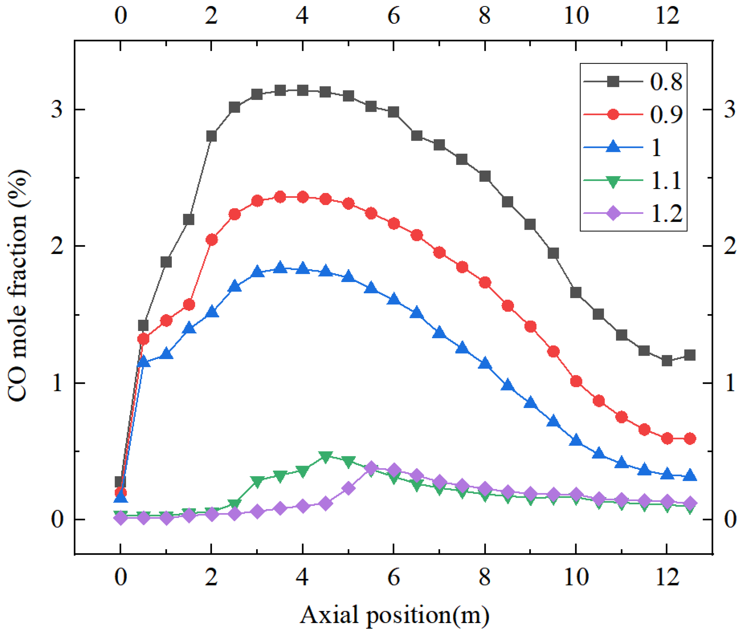
3.4. Effect of Excess Air Factor on the Composition of CO

When the excess air factor is between 0.8 and 1.2, Figure 8 displays the distribution of CO concentration in the burner’s center cross-section. It can be seen from the figure that CO is mainly generated near the entrance of the burner, where the primary air carries an abundance of finely ground coal into the chamber, the amount of oxygen is relatively low, and an abundance of CO is generated by incomplete combustion of the fuel at the initial stage. Under different excess air factors, the distribution of CO mole fraction in the height cross-sectional area of the furnace is basically the same, in the α = 0.8, 0.9, 1.0 of the three conditions basically in accord with the above law. In the α = 1.1, 1.2 of the conditions, the amount of oxygen brought in by the air is more than the volume of oxygen required in a combustion, so in the combustion chamber at the entrance to make the fuel fully combusted, it is difficult to exist at the entrance of the entrance to the CO under the two conditions. The excessive air intake leads a portion of the pulverized coal to be blown to the side of the chamber before it has time to burn. Excessive air intake leads part of the coal dust in the case of combustion before the time to be blown to the side of the furnace chamber, which is attached to the furnace wall. The oxygen blowing in is concentrated in the middle of the furnace chamber, so this part of the coal dust cannot be fully combusted to produce part of the CO. As the value of α decreases, the burnout in the furnace decreases and the CO emission concentration increases, with a maximum CO mole fraction of 0.38% at α = 1.2, and a maximum CO mole fraction of 3.13% at the axial position when α decreases to 0.8. The CO mass fraction tends to decrease with the increase of excess air factor, which is due to the increase of air volume and the increase of oxygen in the furnace. This facilitates the burning of pulverized coal.
As seen in Figure 9, the distribution of CO mass fraction over the furnace height section is essentially the same for various excess air factors. In the main combustion zone, the input of secondary air in the burner area of each floor promotes the coal pulverization and combustion and also has a dilution effect on CO. In addition, the primary air carries a large amount of pulverized coal into the furnace to generate more CO. Therefore, there will be a significant change in the mass fraction of CO in the main combustion zone. In the lower part of the combustion air area, the CO mass fraction changes more gently. This is because the late combustion air to promote the oxidation of CO is in the main combustion area on the one side, and on the other side, the combustion of unburned coke will generate CO. With the combustion air area due to a large amount of dilution of air and the exhaustion of the fuel, the CO mass fraction decreases rapidly. The reducing gas CO, produced during combustion in the furnace, can achieve the reduction of NOX emissions [30], as can be seen from Figure 7 and Figure 9. With the increase of the excess air factors CO and NOX having the opposite trend, in the oxygen-rich combustion CO concentration is at a minimum, the reduction of NOX is very weak, and at this time, the concentration of NOX is high. In the opposite case when the excess air factor is less than 1, more CO is produced due to insufficient combustion and the combustion temperature decreases. Then, the reduction reaction of CO for NOX reduces the overall NOX concentration, and the relationship between the two changes can be clearly seen in Figure 7 and Figure 9.

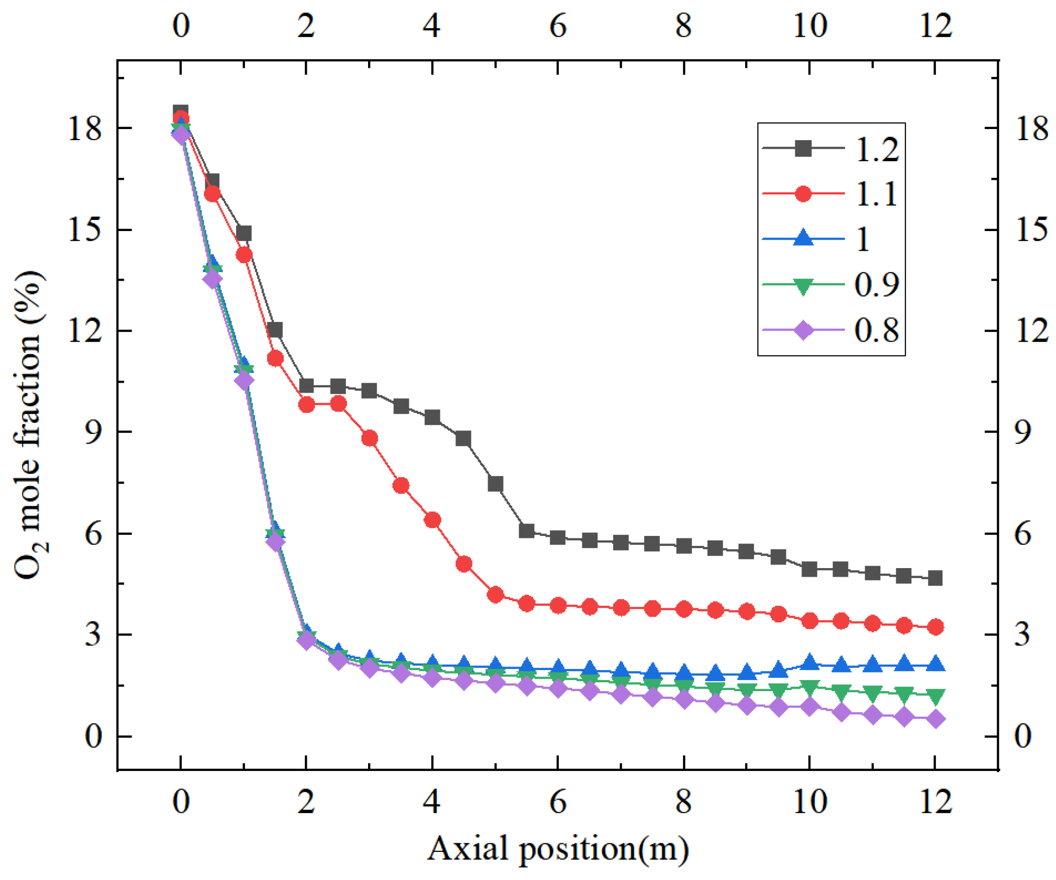
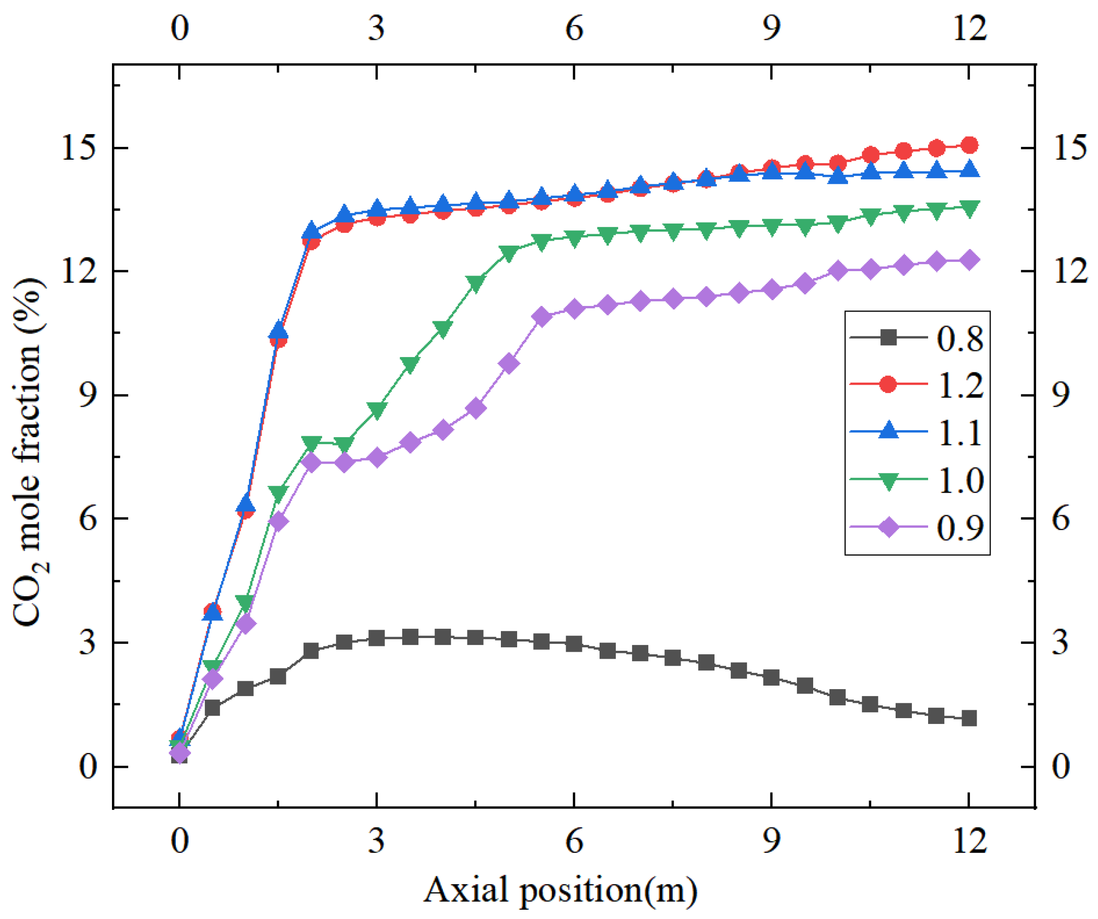
3.5. Effect of Excess Air Factor on CO2, O2

Regardless of the excess air factor, the oxygen concentration is often largest near the burner’s input. Different excess air factors under the O2 mole fraction along the furnace height cross-section distribution law are essentially the same. As the combustion reaction proceeds, the amount of oxygen in the combustion chamber decreases as the pulverized coal reacts with the air. This is because the pulverized coal reacts chemically with the oxygen in the air to produce carbon dioxide, water vapor, and other combustion products. As combustion proceeds, the oxygen in the combustion chamber is consumed, resulting in a gradual decrease in the oxygen content. With the increase in excess air factors into the amount of oxygen, gradually more than the amount of oxygen is needed for chemical reactions in pulverized coal. Combustion of the remaining oxygen increases, so the larger the α, the higher the curve of the oxygen content (Figure 10).
Observations from the cross-section of the furnace chamber show that the distribution of CO2 has a nearly uniform trend for different excess air factors. Since a large amount of pulverized coal is at the combustion start-up stage at the burner inlet, only a small portion of it will participate in the reaction, so less CO2 is produced. The content of CO2 with the increase in combustion, with the increase in the excess air factor of combustion of the oxygen required to make up for it, the fuel can be fully combusted, so the larger the excess air factor, the CO2 content increases faster; then, with the full combustion of pulverized coal into the chamber, the increase in CO2 content tends to level off. The factor α = 1.1, 1.2 when the working conditions of the oxygen content is greater than the amount needed for combustion; the same fuel combustion of CO2 content is generated by the curve of the furnace part of the overlap. The factor α = 0.8 when the air supply is clearly insufficient and the fuel cannot be fully combusted. Only a small amount of CO2 is generated relative to CO, due to incomplete combustion of the fuel to generate a large amount of CO (Figure 11).

4. Conclusions

Based on the results of the above analysis, different excess air factors will cause changes in emissions and will have an impact on the combustion conditions. For the most reasonable boiler operating conditions, look not only at single emissions but to a comprehensive analysis. The average temperature in the central combustion zone increases with the excess air factors. Located at the exit of the combustion chamber, the outlet flue temperature decreases with increasing excess air factor, but the change is not significant. As the excess air factor increases, the CO mass fraction decreases and the NOX concentration increases. In the range of simulated operating conditions, the boiler can achieve the best condition of NOX emission and combustion efficiency when the excess air factor varies from 1.1 to 1.2. There is a maximum peak temperature at an excess air factor of 1.2. When the excess air factor is further reduced to 1, the fuel does not burn sufficiently, resulting in a decrease in the peak temperature. When the excess air factor is less than 1, the combustion is in a fuel-rich state, which does not fully release heat and causes the temperature inside the furnace to decrease slightly. As the excess air factor decreases, the NOX concentration begins to decrease, and when the combustion is in a rich fuel state, the NOX concentration decreases sharply. Reducing the excess air factor reduces NOX emissions. When the excess air factor is less than 1, NOX emissions decrease sharply.
Lower excess air factors are favorable for suppressing the generation of fuel-type NOX excess air factor from 1.2 to 1. CO emissions increase, indicating that continuing to reduce the excess air factor gradually makes fuel combustion difficult; when the excess air factor is less than 1, CO emissions with the reduction of excess air factor increases, this time in a fuel-rich state. The large amount of CO in the furnace under the rich fuel state inhibits the generation of NOX and reduces the NOX emission at the outlet. During combustion, the excess air factor significantly affects the temperature distribution of combustion. The high-temperature region of the flame occupies a larger span of the radial section of the burner. An increase in the excess air factor results in a progressively shorter flame length, which reduces the high-temperature region and to a certain extent destroys the conditions for NOX generation. During the combustion process with different excess air factors, the NOX at the exit of the combustion chamber decreases with the increase of α, and the O2 concentration in the flue gas is higher; when α < 1, the CO concentration is relatively high due to incomplete combustion. CO2 content is negatively correlated with CO. Excess air factors between 1 and 1.2 can reduce NOX emissions under the premise of fuel burnout, and NOX emissions decrease significantly when the excess air factor is less than 1. Therefore, the method of staged combustion can be considered to further inhibit the generation of NOX.
The study can be further subdivided into the change of excess air factors, in order to find the most suitable combustion conditions and the lowest pollution emissions; in order to achieve the effect of energy savings and emission reduction, by changing the excess air factors to observe the change of the relationship between the emission of pollutant gases; and in order to seek in the maximum efficiency of combustion to get the least NOX production.
There is still much room for improvement in the work of this paper, and the next step can be a more detailed study by further subdividing the excess air coefficients based on the results of this paper, changing the number of cyclones on this basis, and observing the effects of different flow characteristics on combustion.

Author Contributions

Conceptualization, L.C. and Y.X.; methodology, S.T. and L.C.; software, Y.X.; validation, L.C., Y.X. and H.L.; formal analysis, H.L.; investigation, L.C.; data curation, S.T.; writing—original draft preparation, L.C., Y.X. and H.L.; writing—review and editing, L.C. and S.T.; visu-alization, Y.X. and S.T.; supervision, H.L.; project administration, L.C.; funding acquisition, L.C. All authors have read and agreed to the published version of the manuscript.

Funding

The funding is provided by the State Grid Company Limited Electric Power Research Institute Science and Technology Project (SGXJJJOOKJJS2310038).

Data Availability Statement

Data are contained within the article.

Conflicts of Interest

The authors declare no conflict of interest.

References

  1. Xi, J.P. Speech at the general debate of the 75th UN General Assembly. People’s Daily, 23 September 2020. [Google Scholar]
  2. Gu, N.Z.; Gu, J.; Zhang, Z.X. The necessity and development trend of desulfurization in small and medium-sized boilers. Ind. Boil. 1999, 2, 4–6. [Google Scholar]
  3. Li, L.L.; Liang, X.; Li, J.J.; Jiao, J.L. Air pollution control policies and air pollution management in China-an empirical study based on city-level panel data. Ecol. Econ. 2024, 40, 179–186. [Google Scholar]
  4. Hao, Q.E.; Wang, F.; Gao, S.H.; Huang, Y. Preparation and performance study of high sulfur-solidifying coal using coal ash residue as sulfur fixing agent. Guangzhou Chem. Ind. 2022, 50, 179–181. [Google Scholar]
  5. Gao, C.Y. Estimation of air pollutant emissions from coal-fired boilers in thermal power plants. Environ. Sci. Manag. 2022, 47, 32–37. [Google Scholar]
  6. Jiang, H.H. Characterization of integrated device for desulfurization wet electric precipitation. Shanxi Metall. 2023, 46, 18–20. [Google Scholar]
  7. He, L.Y.; Han, L.Q. Characterization of combustion conditions in power plant boilers. J. Beijing Technol. Bus. Univ. (Nat. Sci. Ed.) 2008, 4, 55–59. [Google Scholar]
  8. Zhao, X.C.; Wang, J.J. Research on the program to reduce the exhaust temperature of lignite boiler. J. Power Eng. 2023, 43, 686–691+734. [Google Scholar] [CrossRef]
  9. Gao, Y.; Wang, Z.P.; Yan, L.C.; Bai, S.G.; Yang, X.R. A review of the emission characteristics and control of fine particulate matter in the flue gas of pulverized coal boilers. Chem. Manag. 2020, 28, 82–83. [Google Scholar]
  10. Qu, S.J. Industrialization of clean coal technology/new coal chemical industry and its development in China. In Proceedings of the 2013 High-Level Academic Forum of China Coal Society, China; 2013; p. 32. Available online: https://chinacs.kejie.org.cn/about/a1866.html (accessed on 28 July 2024).
  11. Yu, H.; Shen, X.J.; Fu, H. Development and application of desulfurization technology in high temperature flue gas. Energy Conserv. Environ. Prot. 2022, 3, 89–90. [Google Scholar]
  12. Yao, H.J. Comparison and analysis of coal desulfurization technologies. Guangdong Chem. Ind. 2013, 40, 102–103. [Google Scholar]
  13. Xie, Y.; Wang, H.Y.; Zhao, J.; Zhang, C.; Liu, X. Influence of furnace flue gas composition on heat transfer characteristics of oxygen-enriched combustion boilers. Combust. Sci. Technol. 2022, 28, 283–291. [Google Scholar]
  14. Li, Z.Y.; Cheng, J.; Liu, J.Z.; Li, L. Dynamic monitoring and analysis of clean combustion flue gas composition in industrial boilers. Power Stn. Syst. Eng. 2002, 4, 1–4. [Google Scholar]
  15. Li, X.H. Optimization and reconstruction technology of SCR flue gas denitrification ultra low emission in coal fired power plant. In IOP Conference Series: Materials Science and Engineering; IOP Publishing: Singapore, 2017; Volume 231, p. 012111. [Google Scholar]
  16. Cai, R.; Luo, K.; Watanabe, H.; Kurose, R.; Fan, J. Recent advances in high-fidelity simulations of pulverized coal combustion. Adv. Powder Technol. 2020, 31, 3062–3079. [Google Scholar] [CrossRef]
  17. Ghose, P.; Sahoo, T.K.; Sahu, A.K. Pulverized coal combustion computational modeling approach: A review. Proc. Inst. Mech. Eng. Part A J. Power Energy 2023, 237, 797–818. [Google Scholar] [CrossRef]
  18. Rajhi, W.; Basem, A.; Sabri, L.S.; Mohammed, M.M.; Becheikh, N.; Kolsi, L.; Salahshour, S.; Al-Yasiri, M.; Sabetvand, R. A numerical study of catalytic combustion of methane-air in excess oxygen and deficient oxygen environments with increasing initial pressure: A molecular dynamic approach. Case Stud. Therm. Eng. 2024, 57, 104329. [Google Scholar] [CrossRef]
  19. Patel, V.; Shah, R. Experimental investigation on flame appearance and emission characteristics of LPG inverse diffusion flame with swirl. Appl. Therm. Eng. 2018, 137, 377–385. [Google Scholar] [CrossRef]
  20. Zhen, H.S.; Leung, C.W.; Cheung, C.S. Thermal and emission characteristics of a turbulent swirling inverse diffusion flame. Int. J. Heat Mass Transf. 2010, 53, 902–909. [Google Scholar] [CrossRef]
  21. Song, J.; Lu, X.C.; Zhang, L.K. Excess air factors of boiler flue gases. In Proceedings of the 2022 Annual Scientific and Technical Conference of the Chinese Society of Environmental Science—Environmental Engineering Technology Innovation and Application Session (II), Nanchang, China, 20 August 2022; China Society of Environmental Science, Environmental Engineering Branch: Nanchang, China, 2022; p. 4. [Google Scholar]
  22. Lei, X.; Lu, H.; Chang, X.; Zhou, E. Numerical simulation of the influence of gear-type combustion stabilizer on the flow field distribution and combustion products of swirl burner. Case Stud. Therm. Eng. 2024, 55, 104078. [Google Scholar] [CrossRef]
  23. Menni, Y.; Chamkha, A.; Zidani, C.; Benyoucef, B. Numerical analysis of heat and nanofluid mass transfer in a channel with detached and attached baffle plates. Math. Model. Eng. Probl. 2019, 6, 52–60. [Google Scholar] [CrossRef]
  24. Ghose, P.; Patra, J.; Datta, A.; Mukhopadhyay, A. Prediction of soot and thermal radiation in a model gas turbine combustor burning kerosene fuel spray at different swirl levels. Combust. Theory Model. 2016, 20, 457–485. [Google Scholar] [CrossRef]
  25. Richards, A.P.; Fletcher, T.H. A comparison of simple global kinetic models for coal devolatilization with the CPD model. Fuel 2016, 185, 171–180. [Google Scholar] [CrossRef]
  26. Wang, Y.; Zhou, Y. Numerical optimization of the influence of multiple deep air-staged combustion on the NOX emission in an opposed firing utility boiler using lean coal. Fuel 2020, 269, 116996. [Google Scholar] [CrossRef]
  27. Laubscher, R.; Rousseau, P. CFD study of pulverized coal-fired boiler evaporator and radiant superheaters at varying loads. Appl. Therm. Eng. 2019, 160, 114057. [Google Scholar] [CrossRef]
  28. Krzywanski, J.; Sztekler, K.; Szubel, M.; Siwek, T.; Nowak, W.; Mika, L. A comprehensive three-dimensional analysis of a large-scale multi-fuel CFB boiler burning coal and syngas. Part 1. The CFD model of a large-scale multi-fuel CFB combustion. Entropy 2020, 22, 964. [Google Scholar] [CrossRef] [PubMed]
  29. Shang, T. Experimental Study and Numerical Simulation on a Low-NOx Semi-Anthracite Coal Swirl Burner; Tsinghua University: Beijing, China, 2016. [Google Scholar]
  30. Krzywanski, J.; Blaszczuk, A.; Czakiert, T.; Rajczyk, R.; Nowak, W. Artificial intelligence treatment of NOX emissions from CFBC in air and oxy-fuel conditions. In Proceedings of the CFB-11: 11th International Conference on Fluidized Bed Technology, Beijing China, 14–17 May 2014; pp. 619–624. [Google Scholar]
Figure 1. Model diagram of the combustion chamber.
Processes 12 01607 g001
Figure 2. Overall grid.
Processes 12 01607 g002
Figure 3. Different cross-sectional velocity for models with different numbers of grids.
Processes 12 01607 g003
Figure 4. Temperature-distribution cloud of the combustion chamber with different excess air factors.
Processes 12 01607 g004
Figure 5. Velocity distribution in the combustion chamber with different excess air factors.
Processes 12 01607 g005
Figure 6. NOX distribution at different excess air factors.
Processes 12 01607 g006
Figure 7. NOX with different excess air factors.
Processes 12 01607 g007
Figure 8. Cloud view of CO distribution with different excess air factors.
Processes 12 01607 g008
Figure 9. Variation of CO with different excess air factors.
Processes 12 01607 g009
Figure 10. Variation of O2 with different excess air factors.
Processes 12 01607 g010
Figure 11. Variation of CO2 with different excess air factors.
Processes 12 01607 g011
Table 1. Boundary conditions.
Temp (K)Mass Flow Rate (kg/s)Pressure (Pa)
Internal secondary air6042.58101,325
External secondary air60410.17
Primary air34560.70
Central air6040.44
Table 2. Coal quality analysis.
Proximate Analysis (as Received, wt.%)
VarAarMarFCarQ net ar (kJ/kg)
11.9519.4410.0058.6119,289
Ultimate analysis (as received, wt.%)
CarHarSarNarOar
62.123.020.680.714.03
Table 3. Comparison of burner simulation value with the experimental value.
ParameterExperimental ValueSimulation ValueError
NOX404 ppm416 ppm2.97%
Burnout rate99.5%96.59%2.92%
Disclaimer/Publisher’s Note: The statements, opinions and data contained in all publications are solely those of the individual author(s) and contributor(s) and not of MDPI and/or the editor(s). MDPI and/or the editor(s) disclaim responsibility for any injury to people or property resulting from any ideas, methods, instructions or products referred to in the content.

