Article

Effect of Flexible Tank Wall on Seismic Response of Horizontal Storage Tank

1
School of Civil Engineering, Dalian Minzu University, Jinshi Lu Street, Dalian 116650, China
2
School of Civil and Architectural Engineering, Northeast Petroleum University, Fazhan Lu Street, Daqing 163318, China
3
Shenzhen Gas Corporation Ltd., Meiaoba Street, Shenzhen 518040, China
4
College of Civil Engineering, Institution of Disaster Prevention, Xueyuan Lu Street, Sanhe 065201, China
5
College of Transportation Engineering, Dalian Maritime University, Linghai Lu Street, Dalian 116026, China
*
Authors to whom correspondence should be addressed.
Processes 2024, 12(8), 1633; https://doi.org/10.3390/pr12081633
Submission received: 18 June 2024 / Revised: 25 July 2024 / Accepted: 30 July 2024 / Published: 3 August 2024
(This article belongs to the Topic Energy Extraction and Processing Science)

Abstract

:
Horizontal storage tanks are integral to the petrochemical industry but pose significant risks during earthquakes, potentially causing severe secondary disasters. Current seismic designs predominantly assume rigid tank walls, which can lead to an underestimation of seismic responses. This study introduces a novel analysis method for assessing the dynamic response of flexible-walled horizontal storage tanks. By separating the liquid velocity potential into convective and impulsive components and integrating these with beam vibration theory, we developed a simplified mechanical model. A parameter analysis and dynamic response research were conducted using numerical methods. Results indicate that flexible tank walls amplify seismic responses, including liquid dynamic pressure peaks, base shear, and overturning bending moments, compared to rigid walls. Additionally, the impact of flexible walls is more pronounced in tanks with larger radii, aspect ratios, diameter–thickness ratios, and H/R ratios. These findings highlight the necessity for revised seismic design approaches that consider wall flexibility to enhance the safety and resilience of horizontal storage tanks.

1. Introduction

Storage tanks are essential in the petrochemical industry for storing flammable and explosive materials. Ensuring the integrity of these tanks during strong earthquakes is crucial, as damage can lead to severe secondary disasters, including explosions and fires. Consequently, research into the dynamic response and seismic design of storage tanks has garnered significant attention [1,2]. Traditionally, seismic design has relied on the assumption that tank walls are rigid, simplifying the interactions between tank structures and seismic forces, and facilitating straightforward engineering solutions [3,4]. However, failures observed during seismic events have exposed the limitations of this approach, sparking a shift towards more realistic modeling techniques [5].
The rigid wall assumption has been favored for its simplicity and conservative safety margins. However, this simplification often neglects the potential for dynamic interactions between the tank walls and the stored fluid during earthquakes [6]. This oversight has been highlighted by Lyu et al., who identified discrepancies between observed tank failures and predictions made under rigid wall assumptions [7]. These findings indicate a critical need for more accurate modeling approaches that consider the flexibility of tank walls [1,8].
Internationally, the reliance on rigid wall assumptions varies significantly, influenced by local seismic activity and engineering practices. Regions with stringent seismic regulations have gradually shifted towards incorporating the behaviors of more flexible wall structures into their design standards. This shift is less pronounced in regions with infrequent seismic activities or where economic constraints prioritize cost-effective solutions [9]. Güler et al. analyzed historical data from tank failures during earthquakes, suggesting that rigid wall models often fail to predict actual failure modes [10]. Gabbianelli et al. demonstrated how rigid wall assumptions might underestimate stress concentrations at critical points in the tank structure. Meanwhile, researchers have provided statistical evidence of the superior performance of designs that consider wall flexibility [11]. Merino et al. have advocated for a reevaluation of design practices that rely solely on rigid wall models [12].
Recognizing the significance of wall flexibility, recent research has shifted from traditional rigid assumptions to more accurately represent the dynamic behavior of flexible walls under seismic forces. This transition is crucial for developing more resilient seismic design strategies [13]. The study of dynamic responses has become increasingly sophisticated, with advancements in simulation technologies and materials science enhancing our understanding of the interaction between flexible walls and contained fluids during seismic events [14]. High-resolution modeling techniques have significantly improved our comprehension of the dynamic behavior of flexible walls, particularly their interaction with contained fluids [15]. Recent contributions from researchers have been pivotal in this area, employing computational fluid dynamics (CFDs) [16] and finite element analysis (FEA) [17,18,19,20] to simulate the behavior of tank walls, providing insights that challenge and expand upon conventional design practices.
Several recent articles have significantly advanced the field by addressing different aspects of tank wall flexibility and dynamic responses. Lee et al. demonstrated through their simulations how variable wall stiffness impacts the seismic stress distribution across the tank structure, offering design insights that could lead to more tailored and effective seismic design approaches [21]. Hashemi et al. provided a comprehensive evaluation of several retrofitting techniques designed to enhance wall flexibility, comparing their effectiveness in realistic seismic scenarios [22]. Tsipianitis et al. analyzed the long-term performance of flexible-wall tanks under sequential seismic events, proposing modifications to design standards that account for cumulative damage [23]. Lee et al. explored the potential of using advanced polymeric materials to increase the damping characteristics of tank walls, reducing the likelihood of catastrophic failures during high-magnitude earthquakes [24].
In recent years, there has been a significant shift in the seismic design of horizontal storage tanks. Research by Spritzer et al. has increasingly focused on the dynamic interplay between fluid-structure interactions and the flexibility of tank walls under seismic loading. This shift has been driven by catastrophic failures observed in previous seismic events, which highlighted the limitations of traditional design models [25]. Studies by Hernandez-Hernandez et al. have employed advanced simulation technologies to better capture the complex behaviors of tank systems during earthquakes. These studies indicate that designs incorporating flexible walls can mitigate the adverse effects of dynamic seismic forces, leading to safer storage solutions. This manuscript reviews key research from both domestic and international sources, reflecting a global concern for improved seismic safety standards. Recent efforts have aimed to align seismic design standards with these new findings. For instance, Huang et al. proposed a method for analyzing the seismic response of storage tanks under an uneven foundation settlement, highlighting the combined effects of seismic loads and foundational issues [26]. In regions with stringent seismic safety regulations, Verma et al. compare the seismic design of elevated water tanks using Indian and European standards, analyzing key design parameters under different seismic conditions [27].
Several recent articles have significantly advanced the understanding of seismic design for storage tanks. Researchers have investigated the impact of using low-modulus materials on the seismic behavior of tank walls, demonstrating a substantial reduction in stress concentrations, which are crucial for maintaining structural integrity during earthquakes [28]. Additionally, there has been advocacy for a paradigm shift in national design standards based on comprehensive analyses of stress and deformation in tank walls under seismic loads [29]. Experimental tests on new composite materials have shown improvements in the flexibility and crack resistance of tanks, providing valuable insights into the application of these materials in real-world scenarios [30]. The shift in seismic design practices for horizontal storage tanks is not merely a technical evolution but also a response to the urgent need for safer energy and chemical storage solutions worldwide. By adopting more flexible design paradigms, the engineering community can better protect these critical infrastructures from seismic threats.
This paper proposes a theoretical analysis method to calculate the dynamic response of flexible tank walls in horizontal storage tanks. Based on potential fluid theory, this method separates the liquid velocity potential into convective and impulsive components, combining them with beam vibration theory to construct a simplified mechanical model. An example analysis of ground motion response is provided, contributing to the evolving field by offering a practical and innovative approach to seismic tank design.

2. Analysis Method

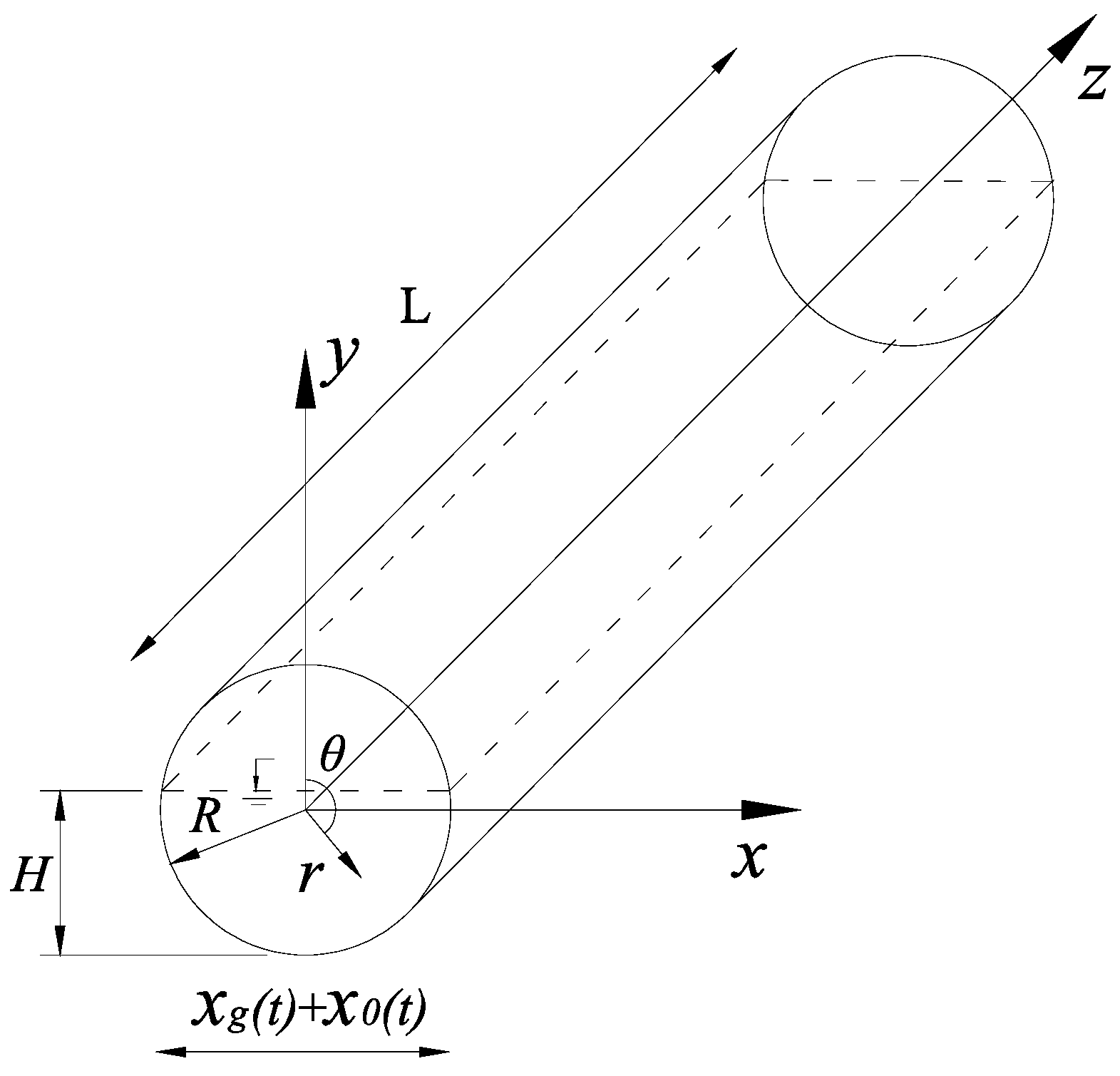
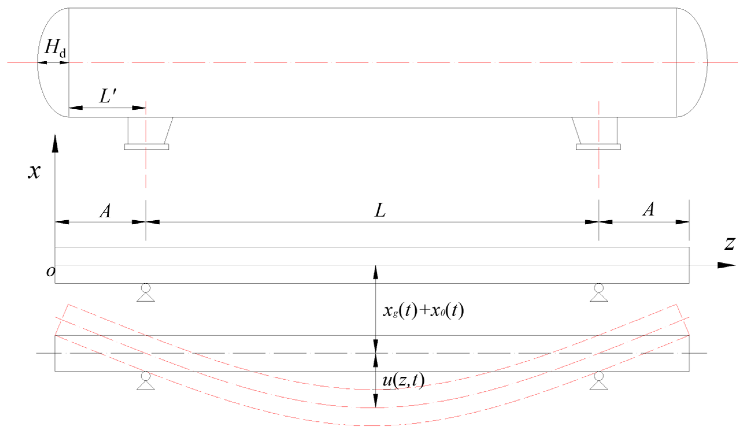
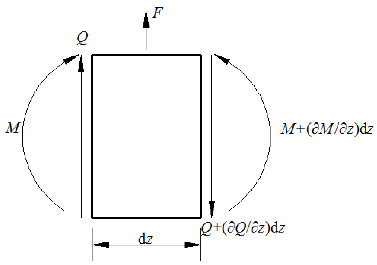
2.1. Fundamental Assumptions

The fluid–tank coordinate system shown in Figure 1 is established. The liquid is assumed to be an ideal fluid that is non-rotating, non-sticky, and incompressible. Under the action of an earthquake, the dynamic pressure of a liquid can be divided into an impulsive component ( P i = ρ φ i t ) and a convective component ( P c = ρ φ c t ), where φ i is the impulsive velocity potential and φ c is the convective sloshing velocity potential, both of which conform to the Laplace equation, as shown in Equation (1).
2 Φ = 2 φ i r , θ , z + 2 φ c r , θ , z = 0
Because the bottom of the saddle is usually bolted, it can be regarded as a hinge. Under the action of a lateral earthquake, the horizontal storage tank can be regarded as a simply-supported beam with extensions, as shown in Figure 2, where A = 2 3 H d + L ; x g t is lateral ground motion; x 0 t is the displacement of the storage tank considering the deformation of the support structure (saddle); and u z , t is the deformation of the tank wall.

2.2. Impulsive Velocity Potential

The impulsive velocity potential should conform to specific boundary conditions, such as Equations (2)–(4).
φ r r r = R = x ˙ g t + x ˙ 0 t + u z , t sin θ
φ i z z = 0 = 0
φ i z z = 2 A + L = 0
The separation of variables method is used to solve the Laplace equation in the cylindrical coordinate system. According to the boundary condition in Equation (2), the general expression of the impulsive velocity potential can be obtained, as shown in Equation (5).
φ i = r x ˙ g t + x ˙ 0 t sin θ + q ˙ t I 1 μ r A 1 sin μ z + A 2   cos μ z sin θ
where I 1 is the Bessel function of virtual quantum. Equation (5) is brought into Equations (3) and (4), respectively, to obtain the values of the undetermined coefficients A 1 , μ , as shown in Equation (6).
A 1 = 0 ,   μ = n π 2 A + L , n = 0 , 1 , 2 , 3 , 4 , .
Superimposing all the characteristic solutions, the expression of the impulsive velocity potential is further expressed as follows:
φ i = r x ˙ g t + x ˙ 0 t sin θ + Ζ T q ˙
In Equation (7), q ˙ = q ˙ t E n   sin     θ   I 1 n π 2 A + L r n × 1 , Ζ = cos n π 2 A + L z n × 1 , where E n is the undetermined coefficient with subscript n.
According to Equation (2),
Ζ T y ˙ = u ˙ z , t sin θ
where y ˙ = q ˙ r r = R . The separation variable method is used to separate u ˙ z , t into two independent components related to t and z, as shown in Equation (9).
According to the beam vibration theory, the vibration mode function of the simply-supported beam with extensions in Figure 2 is as follows:
u ˙ t , z = f ˙ t ψ z
ψ z = i = 1 ϕ i z + j = 1 m γ i j
where ϕ i z = sinh β i z + sin β i z C i cosh β i z + cos β i z , γ i j = R i j sinh β i z z j sin β i z z j h z z j , C i = sinh β A + sin β A cosh β A + cos β A and β i and R i j are constants related to A and L, corresponding to the i-th mode. h z z j is the Heaviside function, defined as h z z j = 1   z z j 0   z < z j , m is the number of simply-supported beams. In this article, m = 2, z 1 = A , z 2 = A + L .
Multiply both sides of Equation (9) by the harmonic matrix Z and integrate over the range of [0, 2A + L]. Because ZT is a diagonal matrix, n independent equations can be obtained:
0 2 A + L q ˙ t E n n π 2 A + L I 1 n π 2 A + L R   cos 2 n π 2 A + L z d z = 0 2 A + L f ˙ t Ψ z c o s n π 2 A + L z d z
According to Equation (11), the undetermined coefficient E n can be obtained. Furthermore, the expression of the impulsive component velocity potential can be obtained, as shown in Equation (12).
φ i = r x ˙ g t + x ˙ 0 t sin θ + f ˙ t n = 0 k n sin θ cos n π 2 A + L z
where k n = 0 2 A + L Ψ z c o s n π 2 A + L z d z I 1 n π 2 A + L r n π 2 A + L I 1 n π 2 A + L R 0 2 A + L cos 2 n π 2 A + L z d z .
We take a micro segment perpendicular to the x-axis for force analysis, as shown in Figure 3.
According to the balance principle and ignoring higher-order components, the balance equations shown in Equations (13) and (14) can be obtained.
Q z d z F = 0
M z d z Q = 0
where Q is the shear force, M is the bending moment, and F is the inertial force and pressure.
F = ρ t A t 2 u + x 0 + x g t 2 d z + 2 ρ l θ π ϕ R ,   θ , z , t t R sin θ   d z d θ
where ρ t is the tank wall density, A t is the tank wall cross-sectional area, ρ l is the liquid density, and R is the tank radius.
According to the mechanics of materials, the relationship between a bending moment and deformation can be obtained, as shown in Equation (16).
M = E I 2 u z 2
where E is the elastic modulus of the tank wall and I is the moment of inertia of the tank wall section.
According to Equations (13)–(16),
E I 4 u z 4 + ρ t A t 2 u t 2 + 2 ρ l θ π ϕ R ,   θ , z , t t R sin θ   d θ = 0
Equation (17) can be regarded as the governing equation of the forced vibration motion of the beam. According to the orthogonality of the mode shapes, we multiply both sides of the equation by the i-th mode shape function and integrate them over the range [0, 2A + L] to obtain the motion control equation of the i-th mode shape. In general, only the first-order vibration mode is considered, as shown in Equation (18).
m ψ M b f ¨ t + K ψ M b f t = x ¨ g t x ¨ 0 t m l M b x ¨ c t
where
m ψ = 0 2 A + L ρ t A t ψ 1 2 z + π θ + sin 2 θ 2 R ρ l ψ 1 z n = 0 k n   cos n π 2 A + L z d z
k ψ = 0 2 A + L E I ψ ¨ ¨ z ψ 1 z d z
M b = π θ + sin 2 θ 2 R 2 ρ l + A t ρ t 0 2 A + L ψ 1 z d z m l = 2 R ρ θ π φ s sin θ   d θ 0 2 A + L ψ 1 z d z
Simplifying Equation (18) further,
x ¨ i t + ω i 2 x i t = x ¨ g t x ¨ 0 t m l M l x ¨ c t
ω i 2 = k ψ m ψ
Where m ψ M b f t = x i ( t ) , and ω i   is the first-order natural frequency of the impulsive component.
According to the above derivation, the expression of the impulsive velocity potential is:
φ i = r x ˙ g t + x ˙ 0 t sin θ + x ˙ t M b m ψ n = 0 k n sin θ cos n π 2 A + L z

2.3. Convective Sloshing Velocity Potential

According to the separation variable method and the boundary conditions, it is easy to discover that the sloshing of the liquid in the horizontal storage tank under lateral seismic excitation is a two-dimensional problem that is independent of z. By solving the Laplace equation in the polar coordinate system, the expression of the convective sloshing velocity potential can be obtained, as shown in Equation (25).
φ s = N T f ˙
where N = r n sin n θ n × 1 , f = f n t n × 1 .
Similarly, the convection sloshing velocity potential needs to meet some specific boundary conditions, as shown in Equations (26) and (27). S1 represents the liquid–solid coupling surface, and S2 represents the free liquid surface. H is the distance from the liquid level to the bottom of the tank.
φ s r r = R = 0 , at S 1
2 φ s t 2 + g φ s y = 2 φ r t 2 2 φ i t 2 g φ i y at S 2 , r = H R c o s   θ
Through coordinate transformation,
φ y = cos θ φ r sin θ r φ θ
Substituting Equation (25) into Equation (26), we multiply the harmonic matrix N r = R on both sides of the equation, and integrate in the S1, as shown in Equation (29).
S 1 N N T f d s = 0
Substituting Equations (24), (25) and (28) into Equation (27), we multiply the harmonic matrix N r = H R c o s θ on both sides of the equation, and integrate in the S2, as shown in Equation (30).
S 2 N N T f ¨ d s + S 2 N N s T f d s = S 2 N 2 φ r t 2 + 2 φ i t 2 + g φ i y d s
The generalized motion control equation can be obtained by adding Equations (29) and (30), as shown in Equation (31).
M f ¨ + K f = S 2 N 2 φ r t 2 + 2 φ i t 2 + g φ i y d s
where
M = S 2 N N T d s ,   K = S 2 N N s T d s + S 1 N N T d s
respectively, generalized mass and stiffness matrix of order n. Equation (31) can be decoupled into n independent motion equations according to the mode superposition method.
m i q i ¨ t + k i q i t = x ¨ g t x ¨ 0 t δ i = 1,2 , 3 , . n
where δ = S 2 ψ i T N 2 φ i t 2 + g φ i y d s μ i , m i = ψ i T M Ψ i μ i , k i = ψ i T K Ψ i μ i , μ i = ψ i T χ , f = i = 1 m Ψ i   q i .
The i-th mode Ψ i and sloshing frequency ω i 2 = ψ i T K Ψ i ψ i T M Ψ i can be obtained according to Equation (34). In general, only considering the first-order sloshing mode, the calculation accuracy can be satisfied [31].
K ω n 2 M ψ n = 0
The expression for sloshing velocity potential can be deduced according to Equation (33).
φ s r , θ , t = λ x ˙ c t
where x c t = m 1 q 1 t , λ = ψ 1 T N m 1 .
2 φ s t 2 + g φ s y = 2 φ r t 2 2 φ i t 2 g φ i y

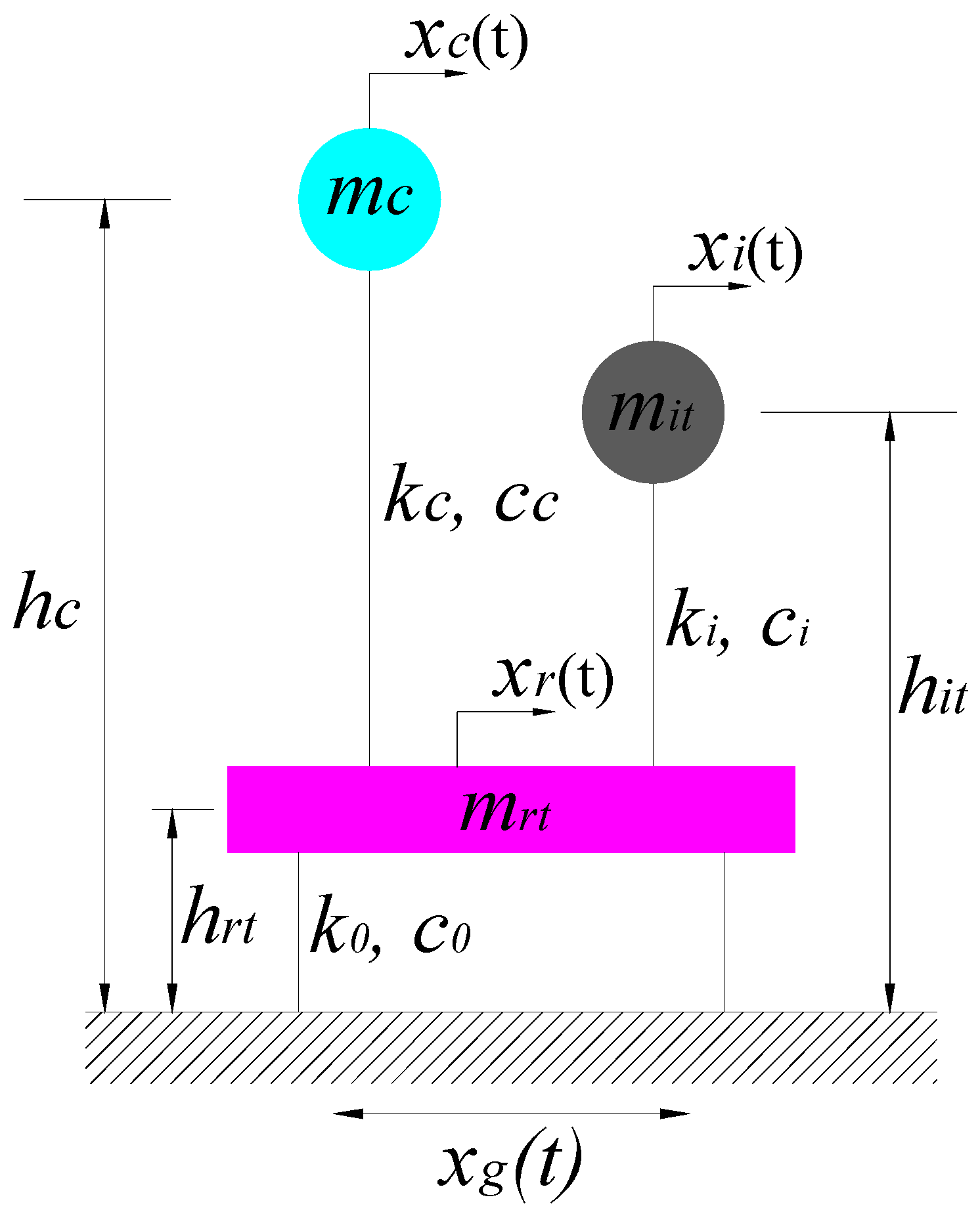
2.4. Simplified Mechanical Model

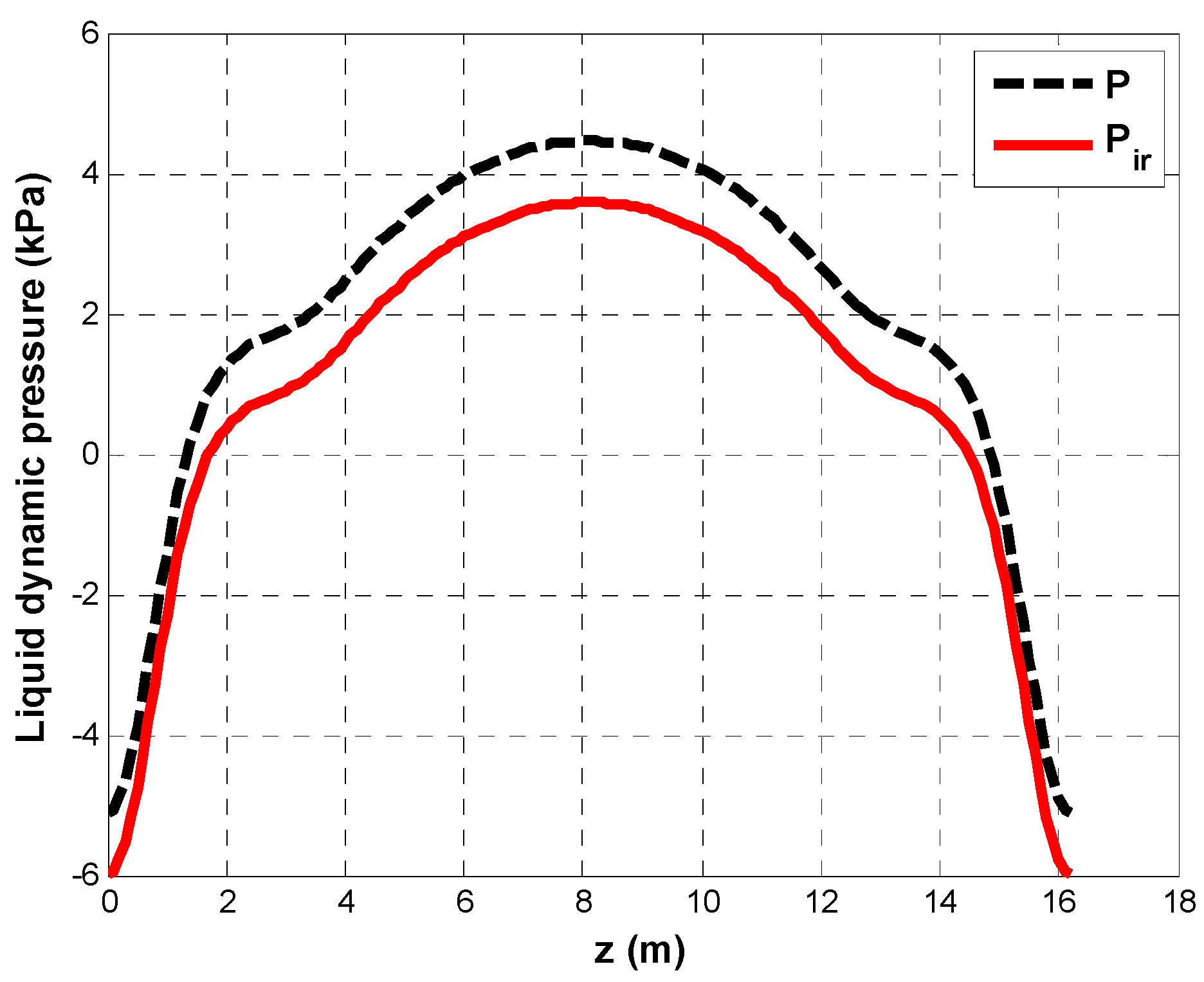
2.4.1. Liquid Dynamic Pressure

According to fluid dynamics, the dynamic pressure acting on the tank wall can be expressed as Equation (36):
P = ρ l φ i + φ s t | r = R
The shear force acting on the saddle due to the dynamic pressure of the liquid can be obtained by integrating P over the surface area S1, as shown in Equation (37).
Q l t = S 1 P sin θ   d s = M L x ¨ g t + x ¨ 0 t m i x ¨ i t m c x ¨ c t
where M L is the total mass of the liquid, m i is the additional component due to the deformation of the tank wall, and m c is the sloshing component. The calculation formulas are shown in Equations (38)–(40), where α = π θ + sin ( 2 θ ) 2 .
M L = α R 2 2 A + L ρ l
m i = M b m ψ α R 0 2 A + L n = 0 k n cos n π 2 A + L z d z
m c = 2 2 A + L R ρ l θ 1 π ψ 1 T N m 1 sin θ   d θ
Because the liquid sloshing period is longer, and the liquid–solid coupling natural vibration frequency is shorter, they can be regarded as two independent mass points, and Equation (41) is transformed into the following expression:
Q l t = m r X ¨ 0 m i X ¨ i m c X ¨ c
where m r = M L m i m c , X ¨ 0 = x ¨ g t + x ¨ 0 t , X ¨ i = x ¨ g t + x ¨ 0 t + x ¨ i t , X ¨ c = x ¨ g t + x ¨ 0 t + x ¨ c t .
Similarly, the bending moment acting on the saddle due to the dynamic pressure of the liquid can be obtained, as shown in Equation (42).
M l t = S 1 P cos θ + R + h sin θ   d s = m r h 0 X ¨ 0 m i h i X ¨ i m c h c X ¨ c
where
h 0 = R + h υ + ϑ m r
h i = R + h υ m i
h c = R + h + ϑ m c
where υ = 2 ρ R 3 2 A + L sin 3 θ ; ϑ = 2 ρ R 2 L θ π ψ 1 T N m 1 sin θ   cos θ   d θ ; h is the height of the saddle.

2.4.2. Tank Wall Inertia Force
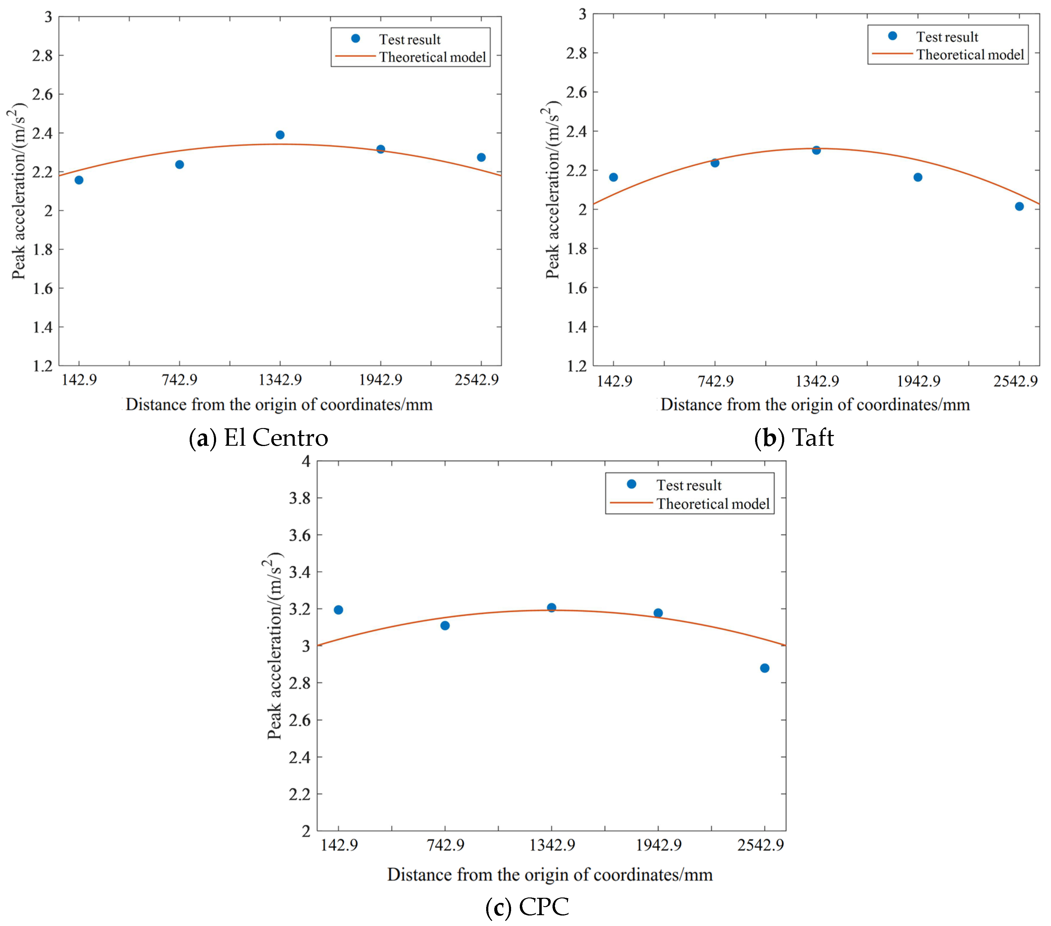
Under the action of ground motion, the effect of tank wall inertia force on the ground motion response cannot be ignored. According to the above derivation, the inertial force of the tank wall is as follows:
Q t t = 0 2 A + L ρ t A t 2 u + x 0 + x g t 2 d z
A simplification of Equation (41) can be obtained:
Q t t = m t 1 X ¨ i + m t 2 X ¨ 0
where m t 2 = m t m t 1 , the equivalent height is R + h.
According to Equations (41), (42) and (47), the simplified mechanical model that considers the effect of a flexible tank wall can be constructed under lateral seismic excitation, as shown in Figure 4.
Where m i t = m i + m t 1 ; h i t = m i h i + m t 1 h + R m i t ; m r t = m r + m t 2   h r t = m r h 0 + m t 2 h + R m r t ; k c = ω c 2 m c , c c = 2 ξ c ω c m c , ξ c is the damping ratio of liquid sloshing; k i = ω i 2 m i t , c i = 2 ξ i ω i m i t , ξ i is the liquid–solid coupling damping ratio. According to the Hamilton principle, the equations of motion in the simplified mechanical model can be derived as shown in Equation (48).
M x ¨ + C x ˙ + k x = M I x g

3. Validation

The following two methods were used to prove the correctness of the proposed simplified mechanical model. First of all, the theoretical basis of the simplified mechanical model is the potential flow theory, which is the most commonly used basic theory to deal with the dynamic response of the fluid–structure coupling of the storage tank. Therefore, the theoretical basis and presupposition of the simplified mechanical model proposed in this paper are reliable.
Then, reference to the experimental results of horizontal storage tank research in the published literature [32] enabled the calculation results of the simplified mechanical model proposed in this paper to be compared to further verify the correctness of the theoretical model.
The parameters of the simplified mechanical model were adjusted to the parameters of the storage tank research in the literature, and three seismic excitations of El Centro, Taft, and CPC reported in the literature were used. This study’s calculated results were compared with the results of the shaking table test that were reported in the literature, as shown in Figure 5 and Table 1.
As is shown in Figure 5, the acceleration peak near the head was smaller, and it was larger near the center of the storage tank. The distribution of closing acceleration was consistent with the calculation results of the simplified mechanical model, as shown in Table 1, and the maximum difference between them was about 5%. The correctness of the simplified mechanical model proposed in this paper was further verified.

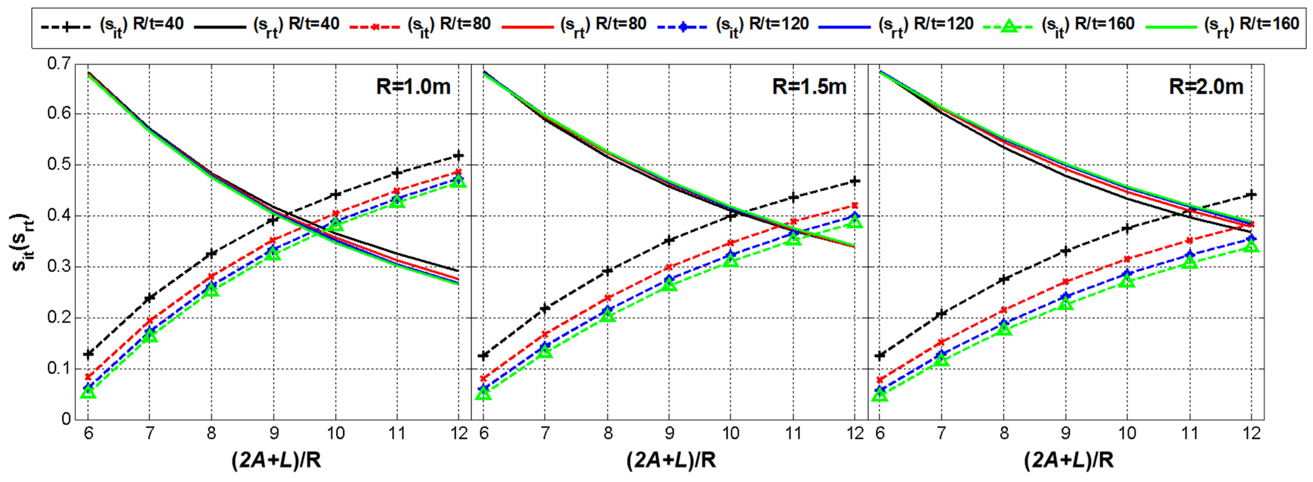
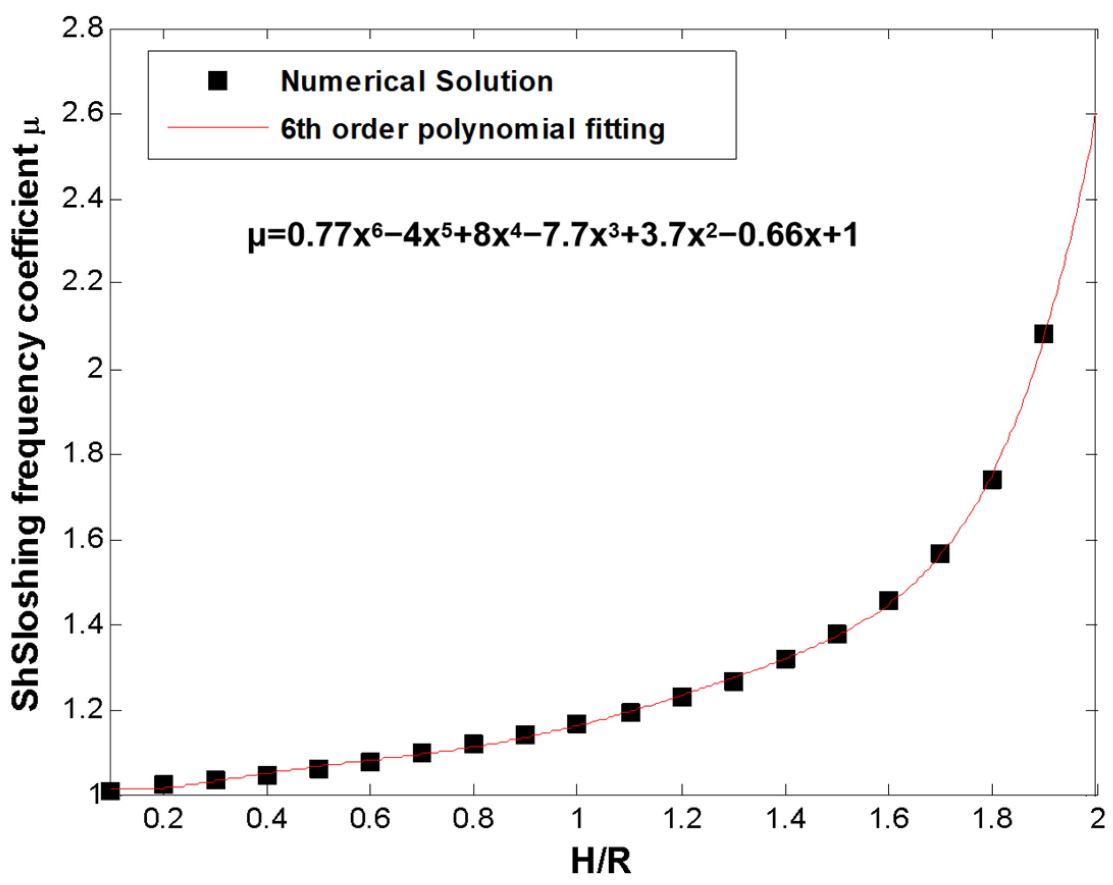
4. Simplified Mechanical Model Parameter Analysis
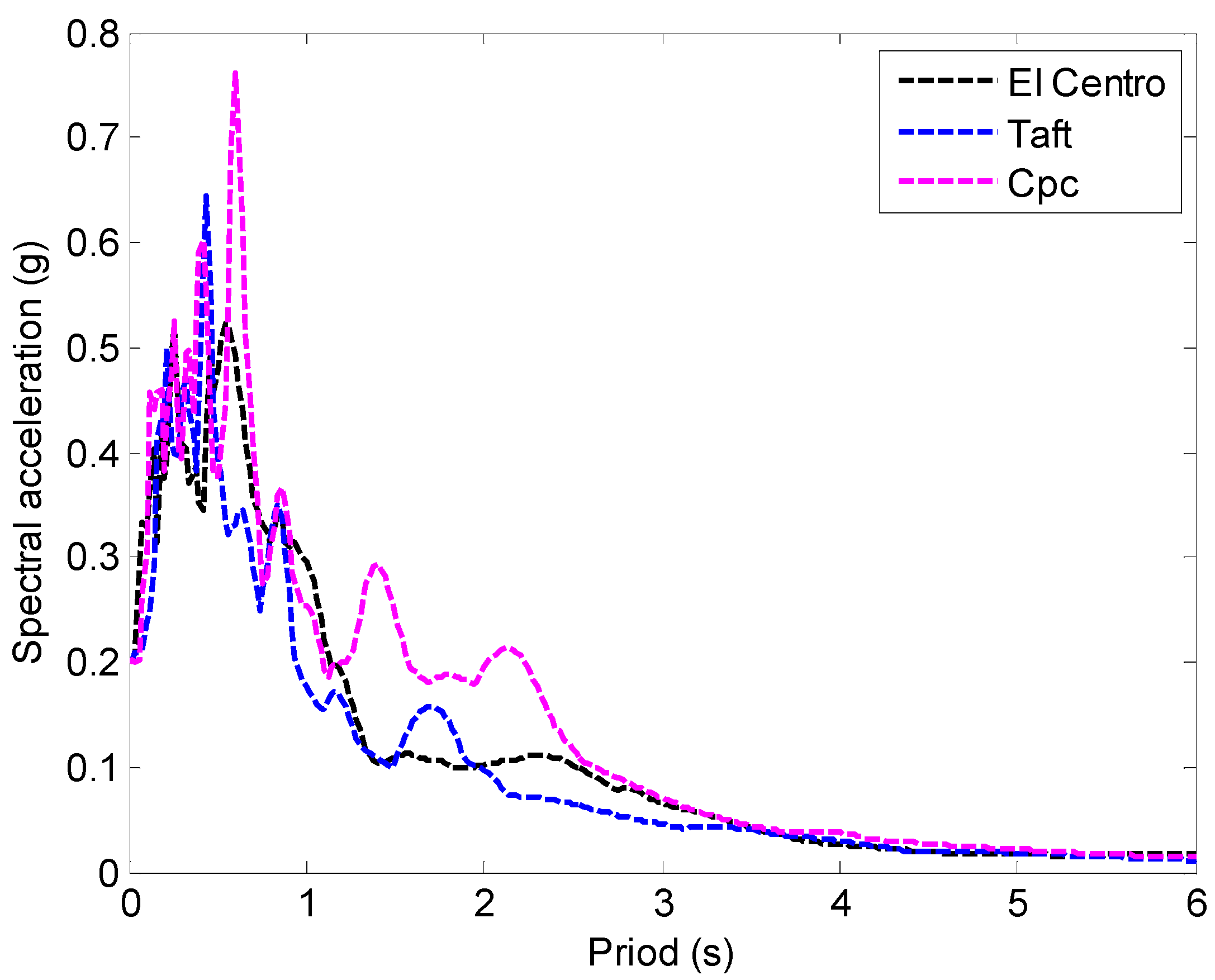
Figure 6 shows the effect of the radius R of the storage tank, the length–diameter ratio (2A + L)/R, and the diameter–thickness ratio R/t on s i t s r t , at the design fill rate 89% (H ≈ 1.5R), where s i t and s r t represent m i t M L + m t and m r t M L + m t , respectively, and t is the wall thickness. In general, A ≈ 0.83R [33].
It can be seen from Figure 5 that as the aspect ratio increased, s i t and s r t showed monotonously increasing and monotonously decreasing distribution, respectively. At the same time, it can be observed that the larger the radius of the storage tank, the greater the mass proportion of m r t , and the smaller the mass proportion of m i t . In addition, the diameter–thickness ratio of the storage tank had little effect on s r t , but s i t showed a decreasing trend as R/t increased.
Based on the above inference, when the proportion of the additional mass m r t is large, the impact of the flexible tank wall on the seismic response is more significant. Therefore, it can be deduced that a greater aspect ratio results in a more pronounced effect of the flexible tank wall on the seismic response.
Figure 7 shows the effect of the radius R of the storage tank, the length–diameter ratio (2A + L)/R, and the diameter–thickness ratio R/t on the natural frequency of the impulsive component f = ω i 2 π at the design filling factor 80% ( H 1.5 R ). It can be seen that as the radius R, aspect ratio, and diameter–thickness ratio increased, f showed a monotonously decreasing distribution. From the data shown in Figure 7, it is evident that the smaller f , the natural frequency, the closer it is to the characteristic frequency range of ground motion, resulting in a more severe seismic response. Therefore, when the radius, aspect ratio, and diameter–thickness ratio of the horizontal storage tank are larger, the impact of the flexible tank wall on the seismic response is more pronounced.
Figure 8 shows the effect of the H/R (the ratio of liquid height to radius) on s i t s r t , at R/t = 120. It can be seen from Figure 8 that s i t and H/R have an inverse relationship. With the increase in H/R, s r t increased first and then decreased. There is an inflection point at H/R ≈ 0.6. Figure 9 shows the effect of the H/R on f = ω i 2 π at R/t = 120. As H/R increased, the natural frequency of the impulsive component gradually decreased, and the greater the influence of the flexible tank wall was.
According to the inference in Section 2.3 and the references [31,34], s c = m c M L (the ratio of convective sloshing equivalent mass to total liquid mass) and the sloshing frequency ω c are the relevant quantities of x = H R . Therefore, it can be fitted to a general formula for x by polynomial fitting. Figure 10 and Figure 11 show the distribution of s c and μ with H/R changes and the corresponding polynomial fitting formula, where ω c = μ g R .

5. Case Analysis

We selected an atmospheric fuel horizontal storage tank as the research object. The storage medium was gasoline, the density was ρ l = 739   kg / m 3 , and the filling factor 0.8 (H ≈ 1.5R). The elastic modulus of the tank wall was E = 2.1 × 10¹¹ N/m2, and the density was ρ t = 7850 kg / m 3 . The specific parameters of the horizontal storage tank are shown in Table 2.
According to the data in the table, it can be calculated that f i = ω i 2 π = 18.97   Hz , s i t = 0.3563 , s r t = 0.3837 , s c = 0.3150 , and f c = ω c 2 π = 0.56   Hz .
Three different earthquake ground motions were used:
a.
El-Centro (EW), Imperial Valley, California, 18 May 1940; duration: 53.46 s;
b.
Taft (NS), Kern County, California, 21 July 1952; duration: 54.36 s;
c.
CPC-TOPANGA CANYON BLVD., Canoga Park, California, 17 January 1994; duration: 55.58 s.
The acceleration peak value of all the seismic waves was adjusted to 0.2 g (PGA = 0.2 g). Figure 12 shows the response spectra of the ground motion records.
Figure 13 shows the distribution of the dynamic pressure peak of the liquid acting on the tank wall along the length of the tank under the action of El-Centro waves. Where P is the total dynamic pressure, Pir is the dynamic pressure of the impulsive component. As can be seen from Figure 13, the dynamic pressure near the saddle was small, while at the middle and both ends of the storage tank it was large. The seismic design of the flexible tank wall of the horizontal storage tank should check the strength of the middle of the storage tank and the connection between the cylinder and the head.
Figure 14 shows the dynamic pressure peak distribution along the liquid height under the action of the El-Centro wave. It can be seen from Figure 14 that the peak value of the liquid dynamic pressure of the flexible tank wall (4.84 kPa, middle of the tank; −5.12 kPa, end of the tank) was much larger than the rigid tank wall (1.47 kPa). Considering the effect of the flexible tank wall, the dynamic pressure peak was amplified approximately 3.0 to 3.5 times compared with the rigid tank wall.
Figure 15 and Figure 16 show the time–history curves of the base shear and bending moments under the action of El-Centro waves. Table 3 presents the peak values of the base shear and the bending moment under the influence of three different seismic waves. As seen in Figure 15 and Figure 16, the flexible tank wall amplified the dynamic response of low-frequency convective sloshing. Table 3 further illustrates that, under the action of the three seismic waves, the flexible tank wall significantly increased the dynamic response of both the base shear and the overturning bending moment compared to the rigid tank wall.

6. Conclusions

This paper proposed a theoretical analysis method that calculated the dynamic response of flexible tank walls in horizontal storage tanks. Based on potential fluid theory, this method divided the liquid velocity potential into convective and impulsive components, combined with beam vibration theory to construct a simplified mechanical model. The following conclusions were obtained through the analysis of examples:
(1)
The influence of a flexible tank wall’s effect on the seismic response of a horizontal tank is closely related to the radius, aspect ratio, diameter–thickness ratio, and H/R of the tank. The larger these parameters are, the more obvious the effect is.
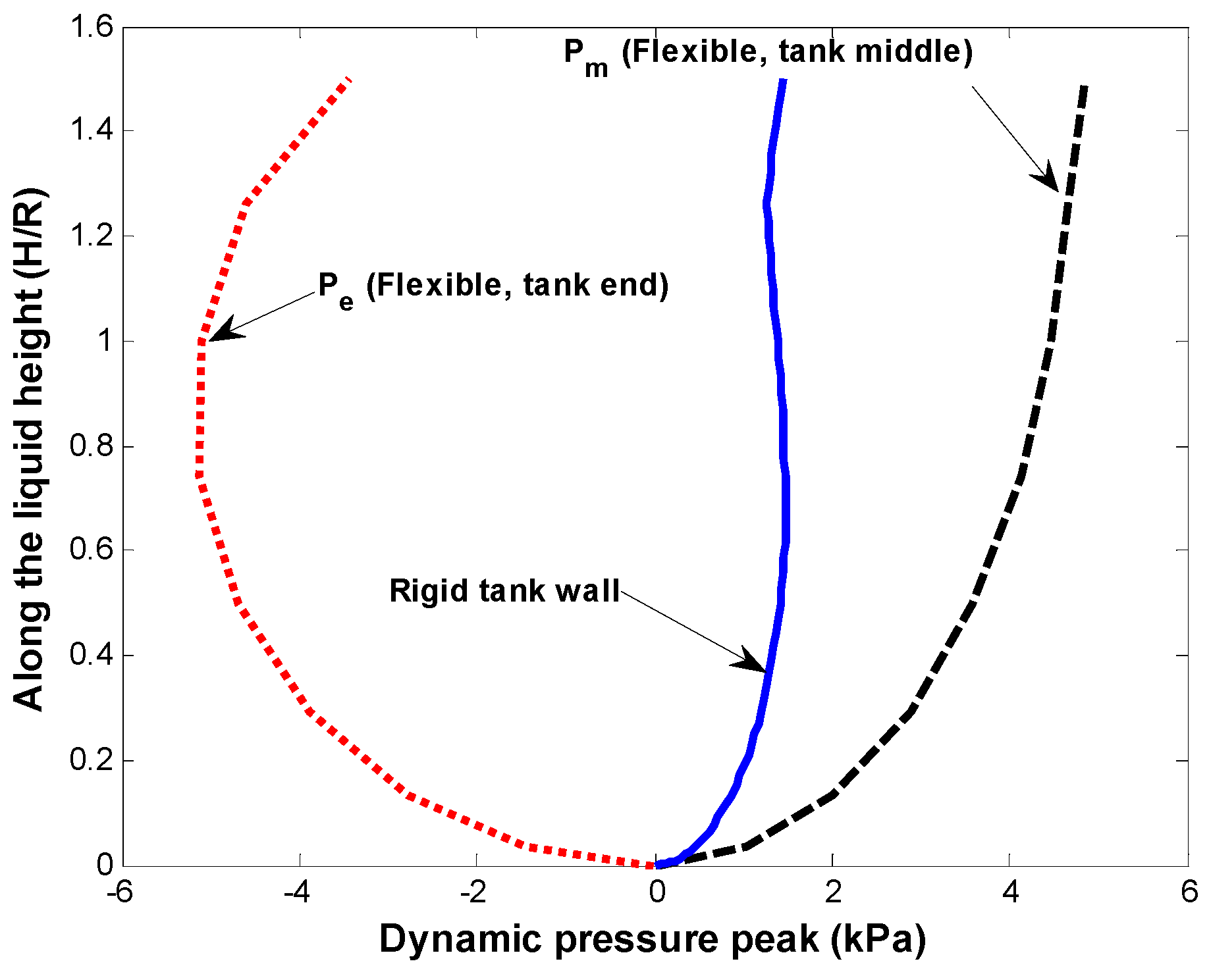
(2)
Considering the flexible tank wall, the liquid dynamic pressure peak appears in the middle of the storage tank and at the connection between the cylinder and the head.
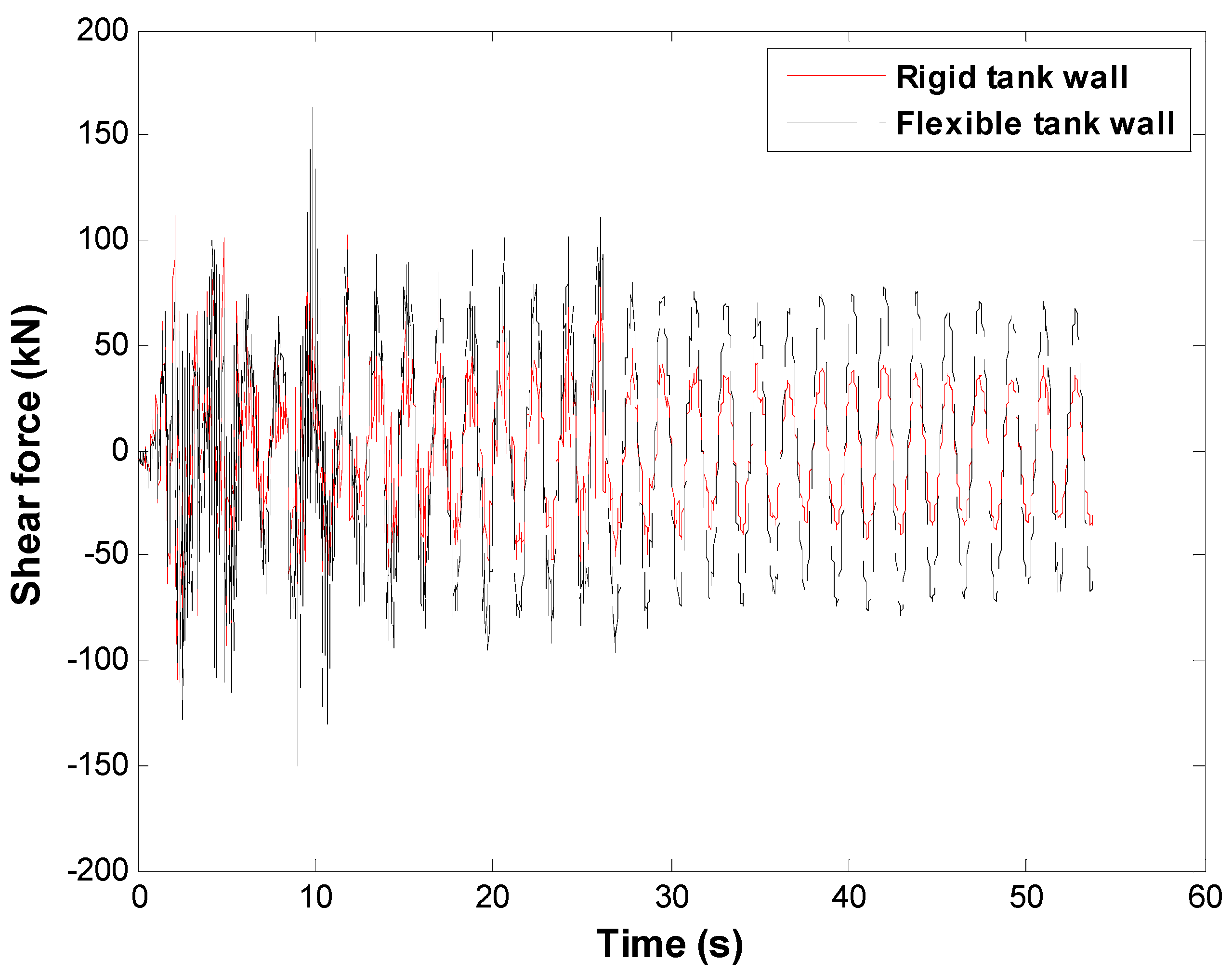
(3)
Compared with a rigid tank wall, a flexible tank wall has an amplification effect on the seismic response of the liquid dynamic pressure peak, base shear, and overturning bending moment.

Author Contributions

L.C.: conceptualization, methodology, and writing—review & editing. L.Z.: formal analysis and visualization. Y.L.: simulation and writing—original draft. J.S.: supervision and writing—reviewing & editing. Y.W.: writing—review & editing. All authors have read and agreed to the published version of the manuscript.

Funding

Financial support was provided by the National Natural Science Foundation of China (No. 51878124) and Liaoning Provincial Natural Science Fund Guidance Plan (20180550073).

Data Availability Statement

The data presented in this study are available on request from the corresponding author.

Conflicts of Interest

Author Yuan Lyu was employed by the company Shenzhen Gas Corporation Ltd. The remaining authors declare that the research was conducted in the absence of any commercial or financial relationships that could be construed as a potential conflict of interest.

References

  1. Fiore, A.; Rago, C.; Vanzi, I.; Greco, R.; Briseghella, B. Seismic behavior of a low-rise horizontal cylindrical tank. Int. J. Adv. Struct. Eng. 2018, 10, 143–152. [Google Scholar] [CrossRef]
  2. Ormeño, M.; Larkin, T.; Chouw, N. Experimental study of the effect of a flexible base on the seismic response of a liquid storage tank. Thin-Walled Struct. 2019, 139, 334–346. [Google Scholar] [CrossRef]
  3. Haroun, M.A.; Housner, G.W. Seismic design of liquid storage tanks. J. Tech. Counc. ASCE 1981, 107, 191–207. [Google Scholar] [CrossRef]
  4. Zhao, Y.; Li, H.-N.; Zhang, S.; Mercan, O.; Zhang, C. Seismic analysis of a large LNG tank considering different site conditions. Appl. Sci. 2020, 10, 8121. [Google Scholar] [CrossRef]
  5. Peek, R. Analysis of unanchored liquid storage tanks under lateral loads. Earthq. Eng. Struct. Dyn. 1988, 16, 1087–1100. [Google Scholar] [CrossRef]
  6. Karamanos, S.A.; Kouka, A. A refined analytical model for earthquake-induced sloshing in half–full deformable horizontal cylindrical liquid containers. Soil Dyn. Earthq. Eng. 2016, 85, 191–201. [Google Scholar] [CrossRef]
  7. Lyu, Y.; Sun, J.-G.; Sun, Z.-G.; Cui, L.F.; Wang, Z. Simplified mechanical model for seismic design of horizontal storage tank considering soil-tank-liquid interaction. Ocean Eng. 2020, 198, 106953. [Google Scholar] [CrossRef]
  8. Hamdan, F. Seismic behaviour of cylindrical steel liquid storage tanks. J. Constr. Steel Res. 2000, 53, 307–333. [Google Scholar] [CrossRef]
  9. Wu, J.-Y.; Yu, Q.-Q.; Peng, Q.; Gu, X.-L. Seismic responses of liquid storage tanks subjected to vertical excitation of near-fault earthquakes. Eng. Struct. 2023, 289, 116284. [Google Scholar] [CrossRef]
  10. Güler, E.; Alhan, C. Performance Limits of Base-Isolated Liquid Storage Tanks with/without Supplemental Dampers under Near-Fault Earthquakes. In Structures; Elsevier: Amsterdam, The Netherlands, 2021; pp. 355–367. [Google Scholar]
  11. Gabbianelli, G.; Milanesi, R.R.; Gandelli, E.; Dubini, P.; Nascimbene, R. Seismic vulnerability assessment of steel storage tanks protected through sliding isolators. Earthq. Eng. Struct. Dyn. 2023, 52, 2597–2618. [Google Scholar] [CrossRef]
  12. Merino, R.; Brunesi, E.; Nascimbene, R. Probabilistic evaluation of earthquake-induced sloshing wave height in above-ground liquid storage tanks. Eng. Struct. 2020, 202, 109870. [Google Scholar] [CrossRef]
  13. Ghoohestani, S.; Shekari, M.R.; Zareifard, M.R.; Amiri, S.M. On the nonlinear seismic response of liquid filled thin-walled steel elevated containers isolated by bearings to earthquake ground motions. Int. J. Press. Vessel. Pip. 2022, 199, 104754. [Google Scholar] [CrossRef]
  14. Park, J.; Askarinejad, H.; Pourbehi, M.S. Seismic evaluation of flexible steel water storage tanks. Proc. Int. Struct. Eng. Constr. 2022, 9, STR28. [Google Scholar]
  15. Bohra, H.; Azzuni, E.; Guzey, S. Seismic analysis of open-top storage tanks with flexible foundation. J. Press. Vessel Technol. 2019, 141, 041801. [Google Scholar] [CrossRef]
  16. Ji, J.; Song, H.; Xu, M.; Li, Z.; Wang, X.; Jiang, L. Finite Element Analysis and Test Verification of Super-Large Vertical Steel Storage Tank; IOP Publishing: Bristol, UK, 2020; p. 012151. [Google Scholar]
  17. Shekari, M.R.; Hekmatzadeh, A.A.; Amiri, S.M. On the nonlinear dynamic analysis of base-isolated three-dimensional rectangular thin-walled steel tanks equipped with vertical baffle. Thin-Walled Struct. 2019, 138, 79–94. [Google Scholar] [CrossRef]
  18. Al-Yacouby, A.M.; Hao, L.J.; Liew, M.; Ratnayake, R.C.; Samarakoon, S.M. Thin-walled cylindrical shell storage tank under blast impacts: Finite element analysis. Materials 2021, 14, 7100. [Google Scholar] [CrossRef] [PubMed]
  19. Rawat, A.; Matsagar, V.A.; Nagpal, A. Numerical study of base-isolated cylindrical liquid storage tanks using coupled acoustic-structural approach. Soil Dyn. Earthq. Eng. 2019, 119, 196–219. [Google Scholar] [CrossRef]
  20. Saria, A.; Djermane, M.; Hadj-Djelloul, N.D. Three-dimensional nonlinear dynamic analysis of base isolated cylindrical steel tank. Civ. Eng. J. 2022, 8, 753–762. [Google Scholar] [CrossRef]
  21. Lee, J.H.; Cho, J.-R.; Han, S.-W. Time-domain earthquake response analysis of rectangular liquid storage tank considering fluid-structure-soil interaction. J. Comput. Struct. Eng. Inst. Korea 2020, 33, 383–390. [Google Scholar] [CrossRef]
  22. Hashemi, S.; Ehteshami, A.; Rahmani, B. Dynamic behavior of elevated and ground-supported, base-isolated, flexible, concrete cylindrical fluid containers. J. Struct. Constr. Eng. 2021, 8, 345–366. [Google Scholar]
  23. Tsipianitis, A.; Tsompanakis, Y. Optimizing the seismic response of base-isolated liquid storage tanks using swarm intelligence algorithms. Comput. Struct. 2021, 243, 106407. [Google Scholar] [CrossRef]
  24. Lee, J.-H.; Cho, J.-R. Simplified earthquake response analysis of rectangular liquid storage tanks considering fluid-structure interactions. Eng. Struct. 2024, 300, 117157. [Google Scholar] [CrossRef]
  25. Spritzer, J.; Bohra, H.; Guzey, S. Imperfection-sensitivity of unanchored aboveground open-top steel welded liquid storage tanks subjected to seismic loads. SN Appl. Sci. 2019, 1, 1–21. [Google Scholar] [CrossRef]
  26. Huang, J.; Chen, Z.; Jiao, P. Seismic Dynamic Response Analysis of Liquid Storage Tank Under Uneven Foundation Settlement Based on Fluid-Structure Interaction. In Pressure Vessels and Piping Conference; American Society of Mechanical Engineers: New York City, NY, USA, 2023. [Google Scholar]
  27. Verma, S. Seismic Analysis of Circular Elevated Water Tank Designed by Indian Standard and European Standard Code. Int. J. Res. Appl. Sci. Eng. Technol. 2021, 9, 1638–1641. [Google Scholar] [CrossRef]
  28. Mamaghani, I.H.P.; RoopKumdee, W. Seismic Response of LNG Storage Tanks under Earthquake Excitations. In Proceedings of the 6th International Conference on Civil, Structural and Transportation Engineering, Online, 17–19 May 2021. [Google Scholar]
  29. Phan, H.N.; Paolacci, F.; Di Filippo, R.; Bursi, O.S. Seismic vulnerability of above-ground storage tanks with unanchored support conditions for Na-tech risks based on Gaussian process regression. Bull. Earthq. Eng. 2020, 18, 6883–6906. [Google Scholar] [CrossRef]
  30. Luo, D.; Liu, C.; Sun, J.; Cui, L.; Wang, Z. Liquefied natural gas storage tank simplified mechanical model and seismic response analysis. Soil Dyn. Earthq. Eng. 2021, 141, 106491. [Google Scholar] [CrossRef]
  31. Patkas, L.; Karamanos, S. Variational solutions for externally induced sloshing in horizontal-cylindrical and spherical vessels. J. Eng. Mech. 2007, 133, 641–655. [Google Scholar] [CrossRef]
  32. Lyu, Y.; Sun, J.-G.; Sun, Z.-G.; Cui, L.-F.; Wang, Z. Seismic response calculation method and shaking table test of horizontal storage tanks under lateral excitation. Earthq. Engng. Struct. Dyn. 2021, 50, 619–634. [Google Scholar] [CrossRef]
  33. HG-T-3154; Standard of Ministry of Chemical Industry of the People’s Republic of China: Horizontal Oval Head Storage Tank Series. Ministry of Chemical Industry of the People’s Republic of China: Beijing, China, 1985.
  34. McIver, P. Sloshing frequencies for cylindrical and spherical containers filled to an arbitrary depth. J. Fluid Mech. 1989, 201, 243–257. [Google Scholar] [CrossRef]
Figure 1. Horizontal tank schematic.
Processes 12 01633 g001
Figure 2. Outrigger beam structure.
Processes 12 01633 g002
Figure 3. Micro-section force analysis chart.
Processes 12 01633 g003
Figure 4. Simplified mechanical model that considers the effect of flexibility.
Processes 12 01633 g004
Figure 5. The horizontal lateral peak acceleration along the tank axis.
Processes 12 01633 g005
Figure 6. Effect of the radius R, the length–diameter ratio (2A + L)/R, and the diameter–thickness ratio, R/ton s i t s r t .
Processes 12 01633 g006
Figure 7. Effect of the radius R, the length–diameter ratio (2A + L)/R, and the diameter–thickness ratio, R/ton f = ω i 2 π .
Processes 12 01633 g007
Figure 8. Effect of the H/R on s i t s r t .
Processes 12 01633 g008
Figure 9. Effect of the H/R on f = ω i 2 π .
Processes 12 01633 g009
Figure 10. Effect of the H/R on s c = m c M L .
Processes 12 01633 g010
Figure 11. Effect of the H/R on the sloshing frequency coefficient.
Processes 12 01633 g011
Figure 12. Target spectrum and response spectra of the ground motion records.
Processes 12 01633 g012
Figure 13. Dynamic pressure peak along the length of the tank.
Processes 12 01633 g013
Figure 14. Dynamic pressure along the liquid height.
Processes 12 01633 g014
Figure 15. Shear force time–history curve.
Processes 12 01633 g015
Figure 16. Bending moment time–history curve.
Processes 12 01633 g016
Table 1. Comparison of peak acceleration along the tank axis.
Seismic ExcitationComparison ItemMeasuring Point
El CentroAnalytical solutions (m/s2)2.2072.3082.3422.3082.208
Test results (m/s2)2.1572.2372.3902.3162.274
Error (%)2.273.08−2.05−0.35−2.99
TaftAnalytical solutions (m/s2)2.0762.2522.3112.2522.076
Test results (m/s2)2.1642.2372.3022.1642.015
Error (%)−4.230.670.393.912.94
CPCAnalytical solutions (m/s2)3.0343.1523.1923.1523.034
Test results (m/s2)3.1943.1093.2063.1772.879
Error (%)−5.271.36−0.44−0.795.11
Table 2. Horizontal tank geometry parameters.
PartsStructural ParametersSize/mm
Oval headHead depth790
Head wall thickness12
Tank bodyLength1460
Inside diameter3000
Wall thickness12
SaddleDistance from the center of the saddle to the tangent of the head800
Width360
Height250
Saddle wrap angle120º
Table 3. Peak seismic response.
Seismic ResponseAnalysis MethodEl-CentroTaftCPC
Shear force (kN)Flexible 163.0152.1159.6
Rigid111.2124.7137.1
Error (%)−46.58−21.97−16.48
Bending moment (kN·m)Flexible 222.4219.7226.1
Rigid163.7189.3204.5
Error (%)−35.86−16.06−10.56
Disclaimer/Publisher’s Note: The statements, opinions and data contained in all publications are solely those of the individual author(s) and contributor(s) and not of MDPI and/or the editor(s). MDPI and/or the editor(s) disclaim responsibility for any injury to people or property resulting from any ideas, methods, instructions or products referred to in the content.

