
A Study on the Influence of Radial Spoiler Arrangement on the Combustion Process of Wankel Rotor Engines


Abstract
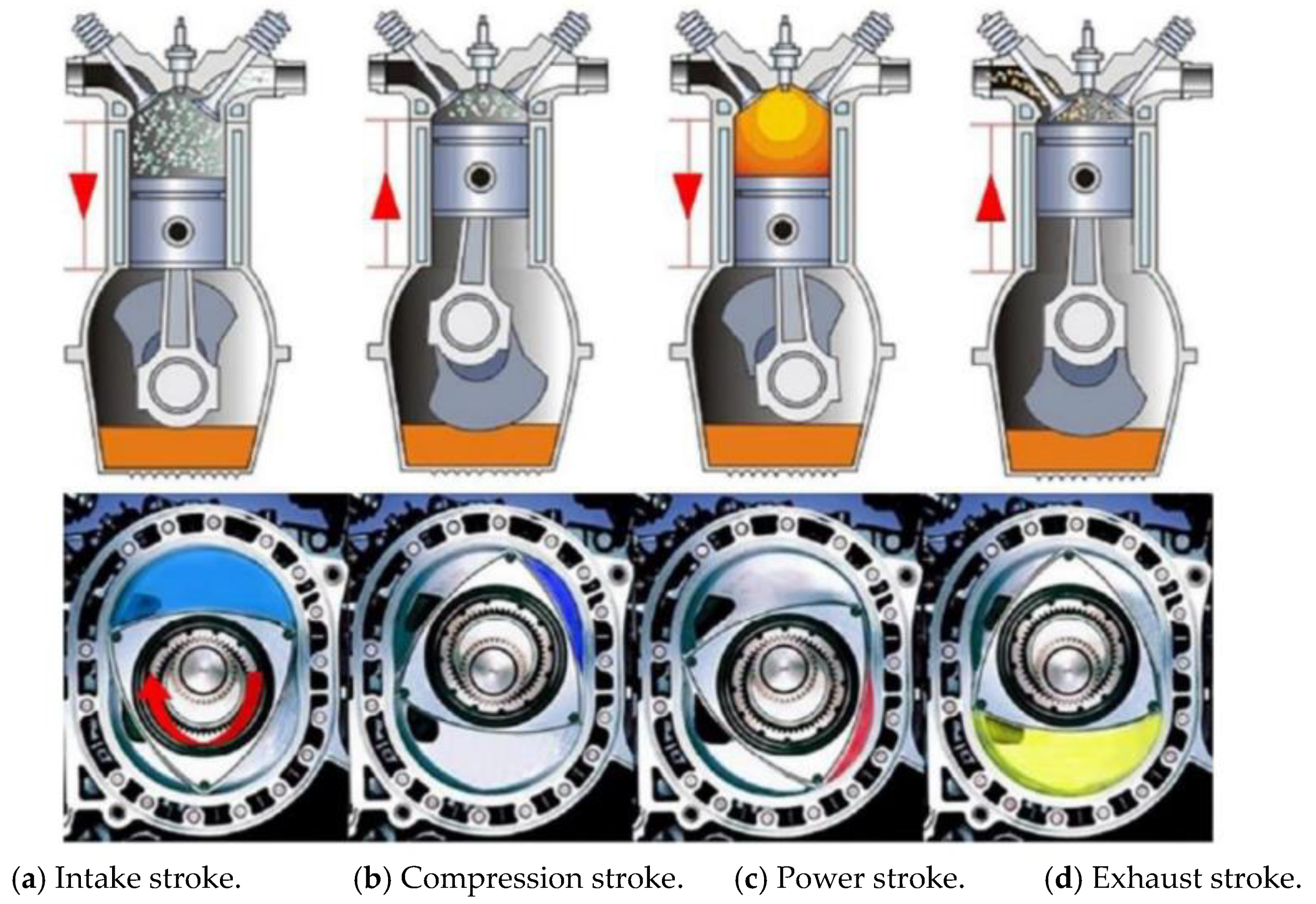
:1. Introduction
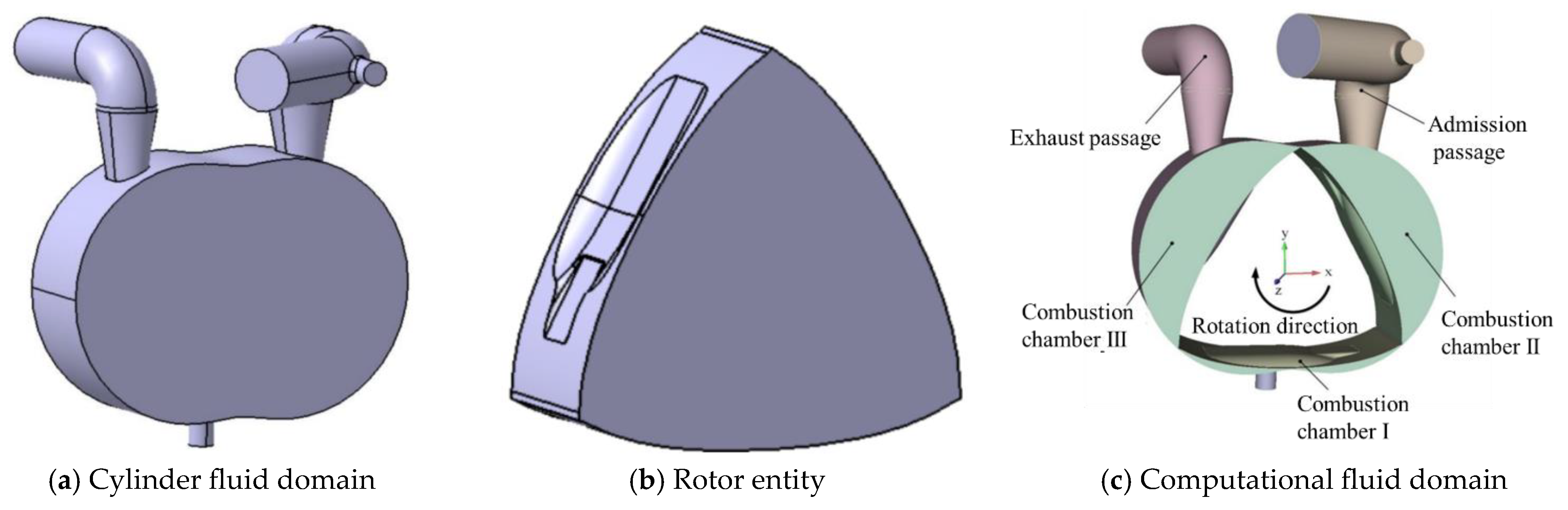
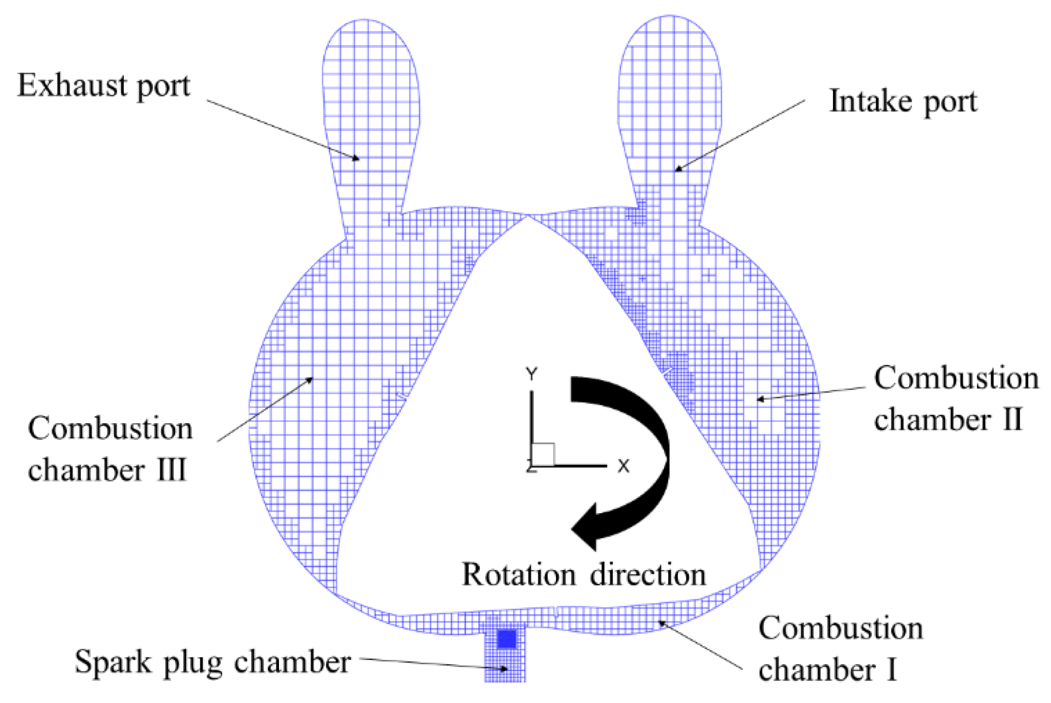
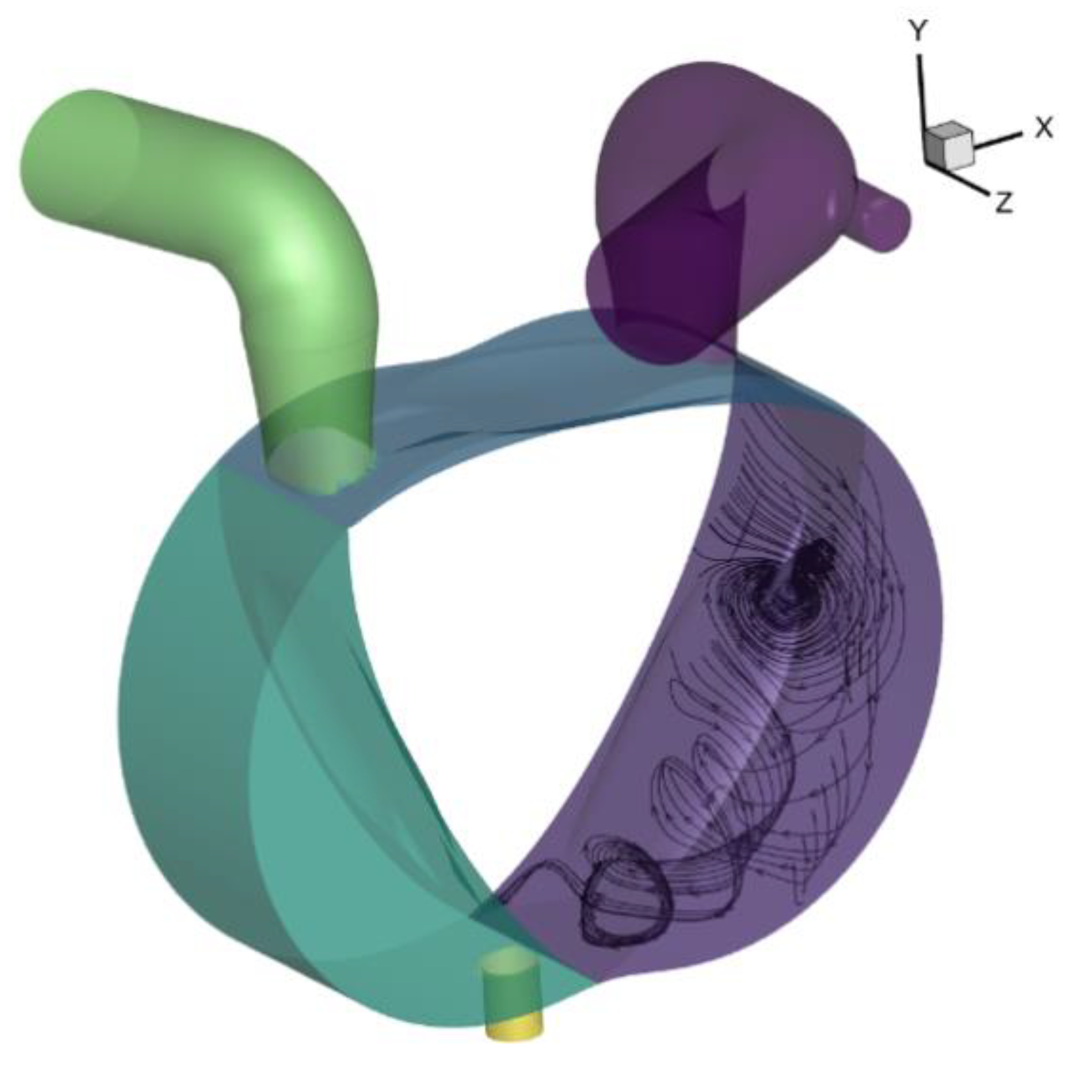
Establishment of Simulation Model of Wankel Rotor Engine
2. Methods and Results
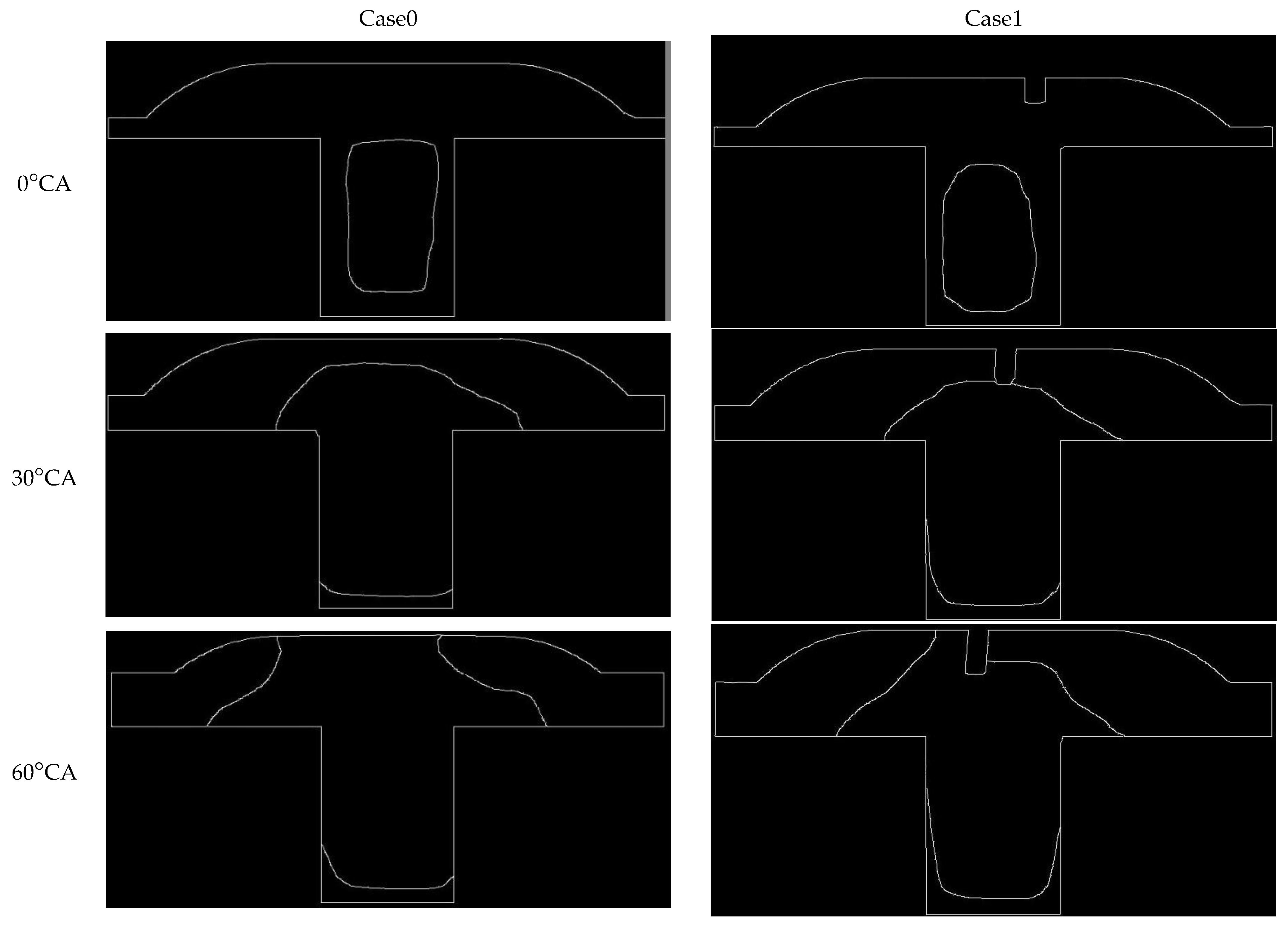
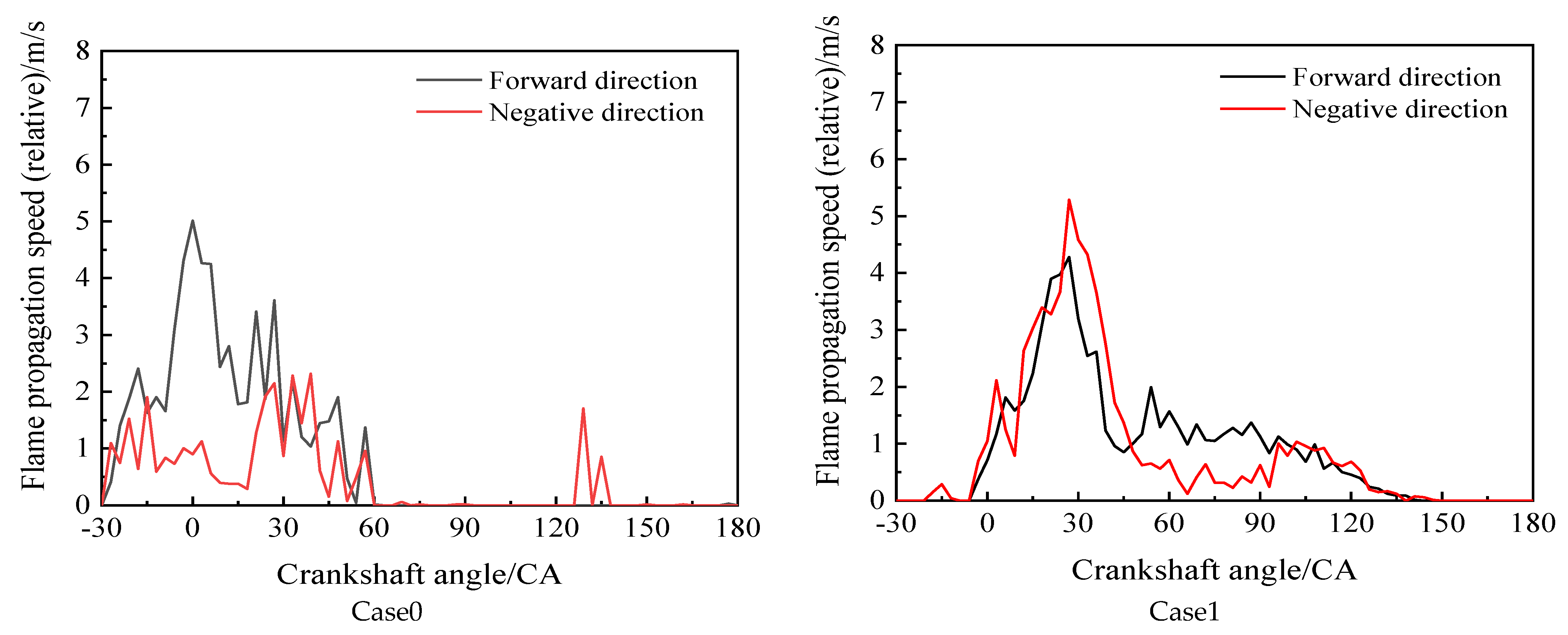
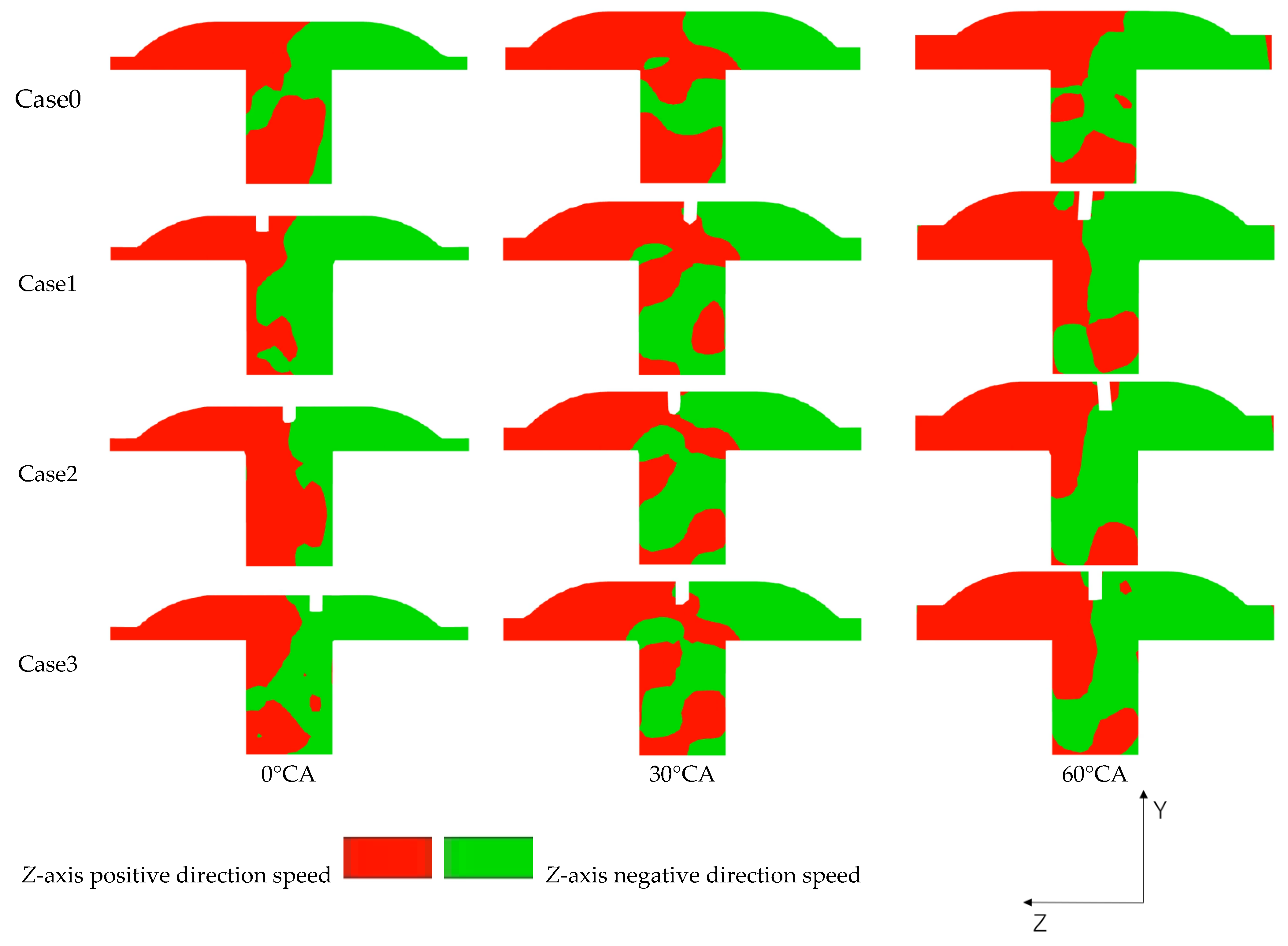
2.1. Analysis of the Influence of Radial Spoilers on Flame Propagation Speed
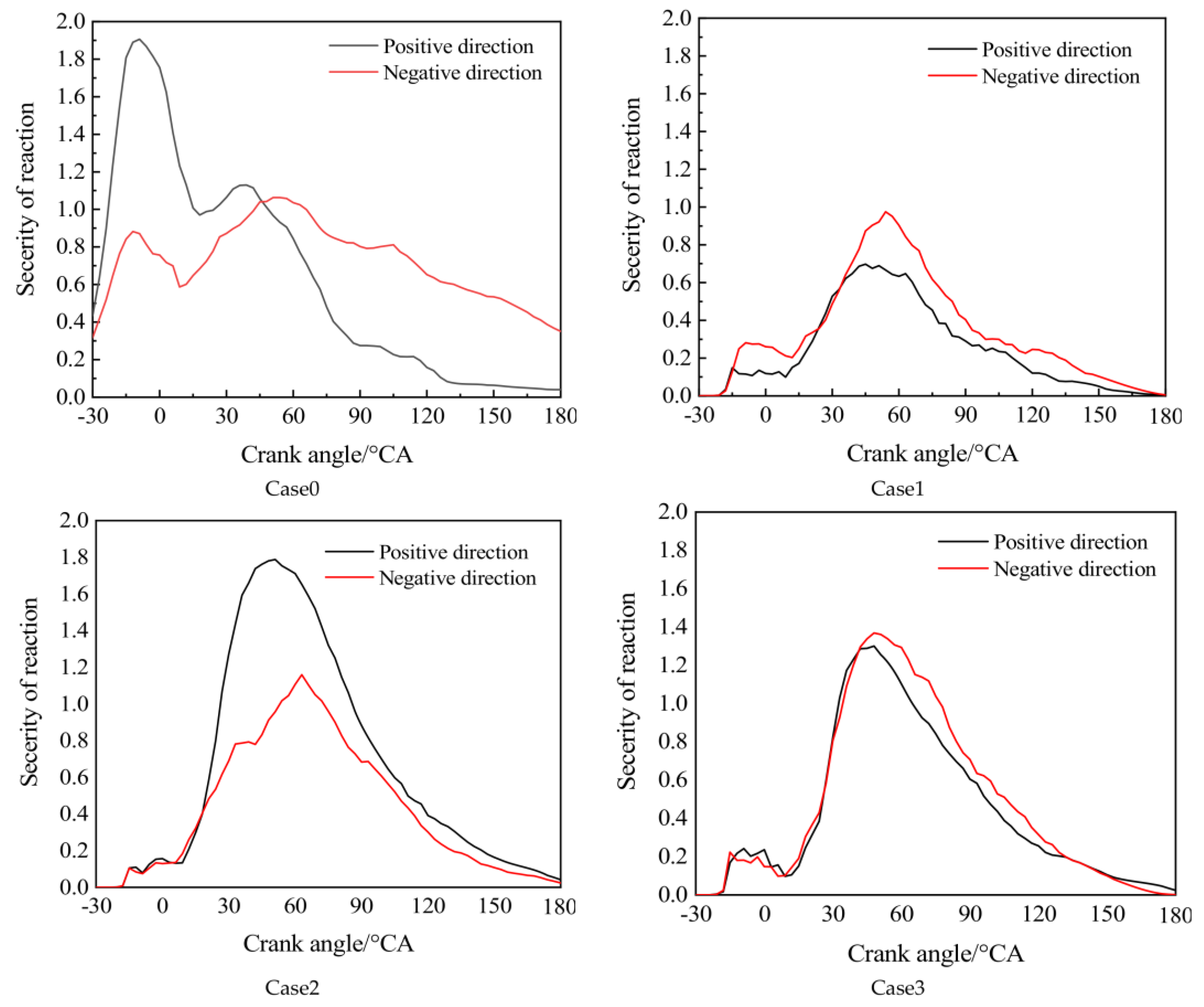
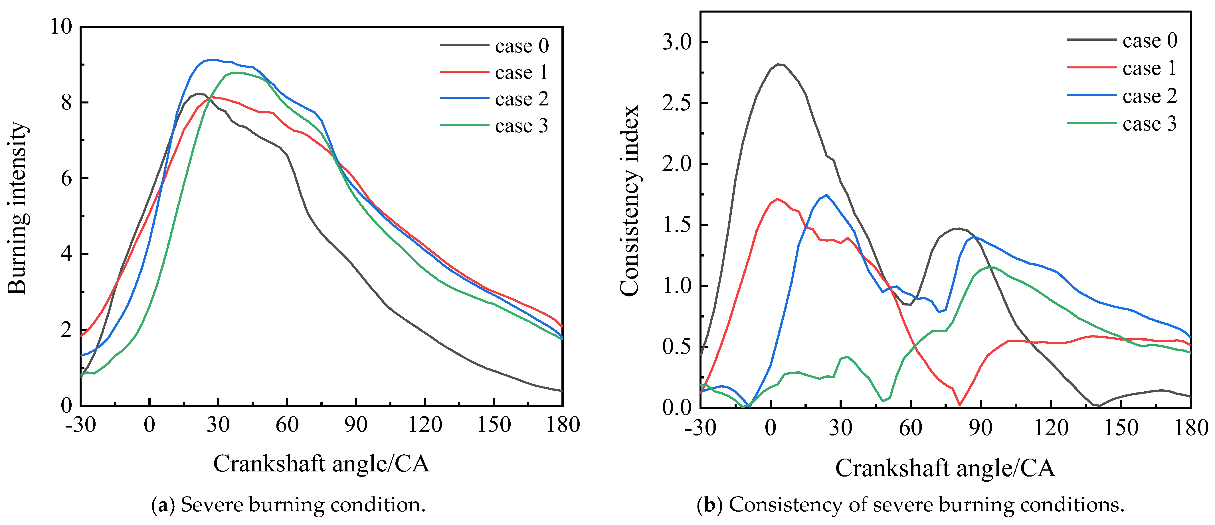
2.2. Analysis of the Impact of Radial Spoilers on the Severity of the Reaction
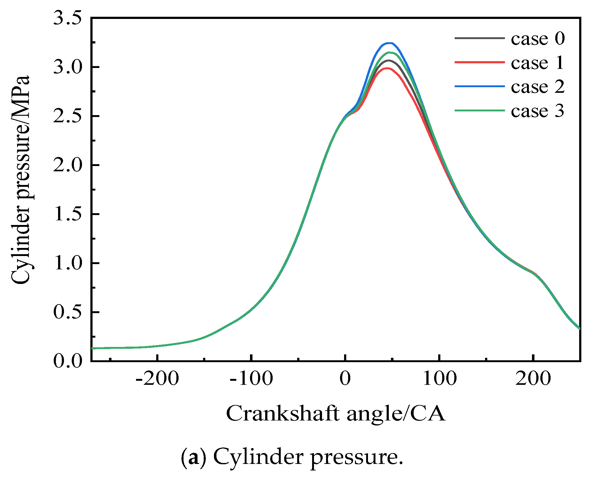
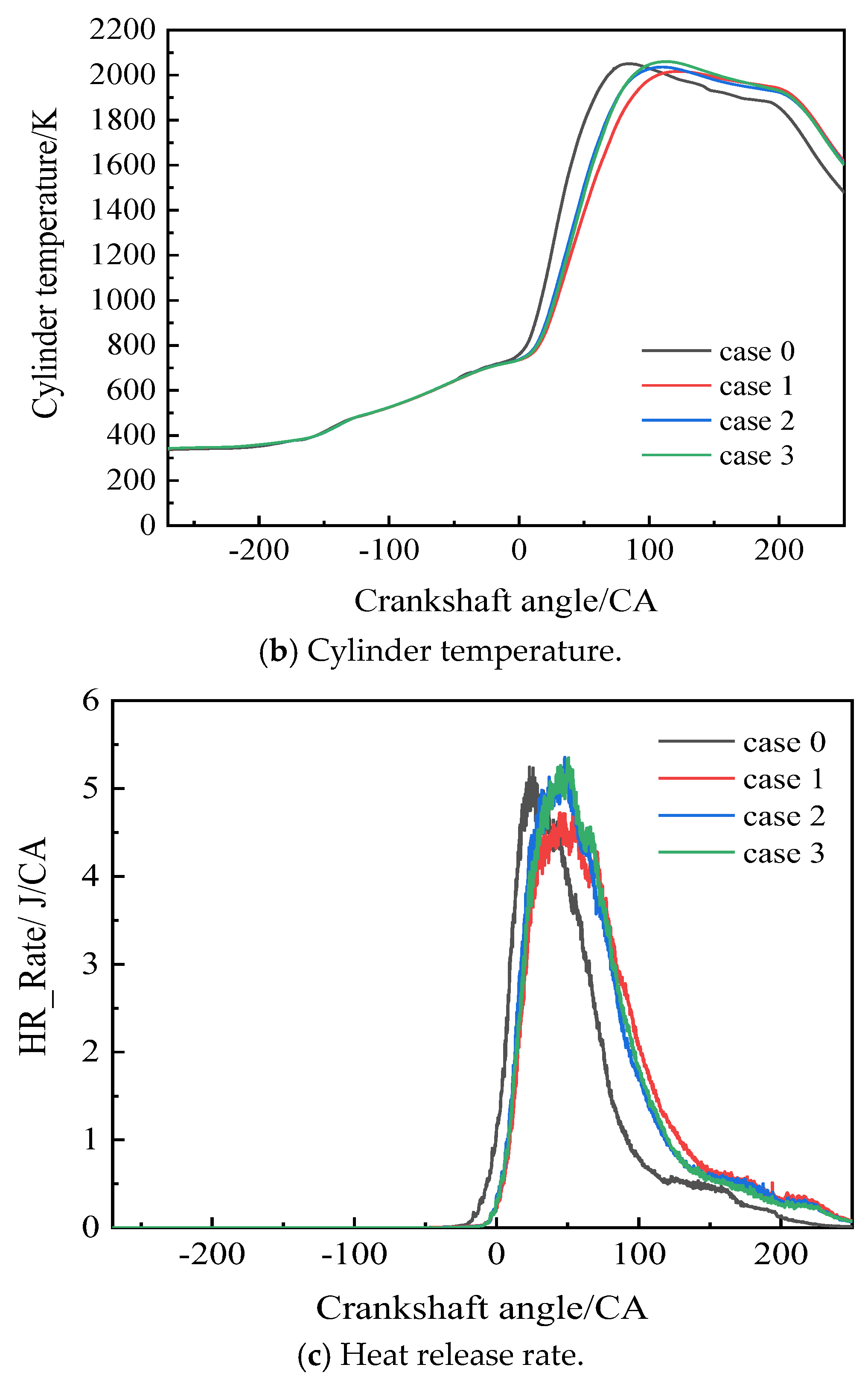
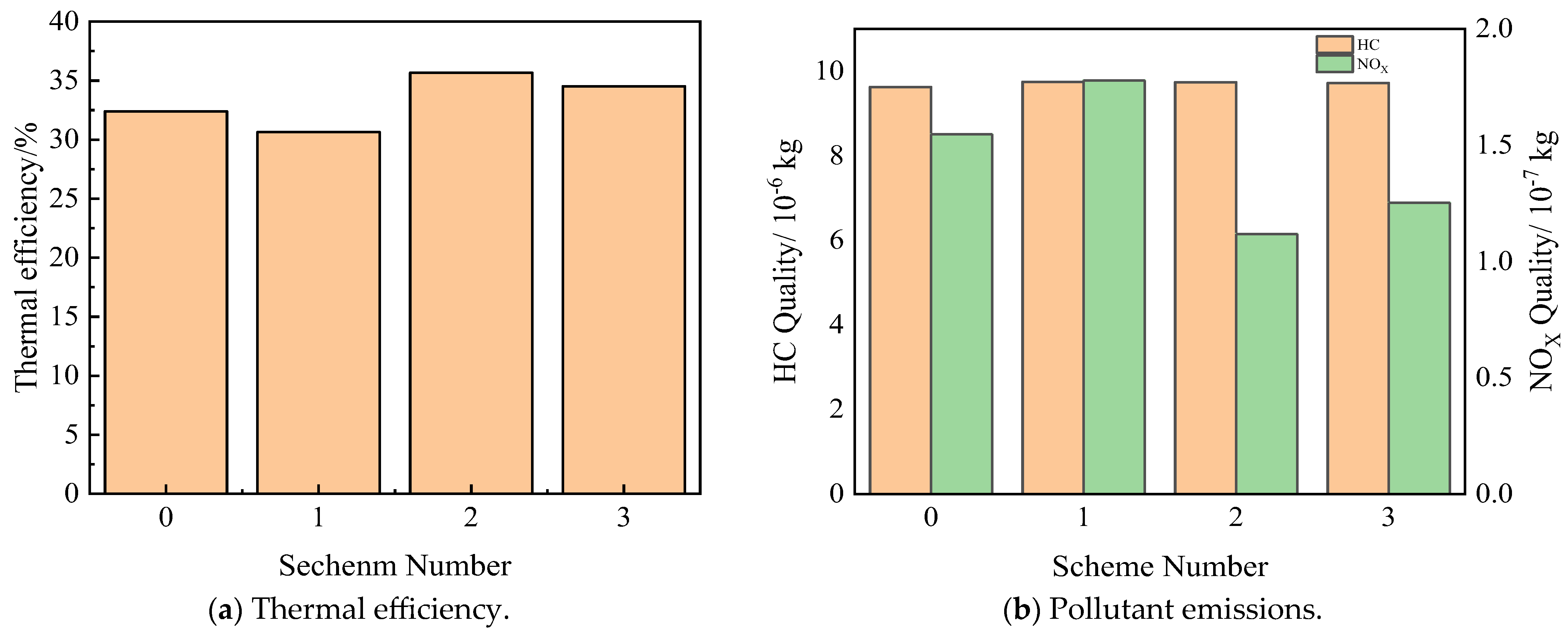
2.3. Analysis of the Impact of Radial Spoilers on Combustion Consistency and Performance
3. Conclusions
Author Contributions
Funding
Data Availability Statement
Conflicts of Interest
References
- Fan, B.; Pan, J.; Huang, J. The influence of combustion chamber structure on the combustion process of natural gas rotary engines. J. Mech. Eng. 2015, 51, 141–151. [Google Scholar] [CrossRef]
- Zhao, Y.; Deng, X.; Feng, Z. The influence of combustion chamber depression shape on the combustion process of gasoline rotary engines. Automot. Eng. 2022, 151–168. [Google Scholar]
- Kuo, C.H.; Ma, H.L.; Chen, C.C. Chamber contour design and compression flow calculations of rotary engine. J. CCIT 2010, 39, 35–50. [Google Scholar]
- Tartakovsky, L.; Baibikov, V.; Gutman, M.; Veinblat, M.; Reif, J. Simulation of Wankel Engine Performance Using Commercial Software for Piston Engines; SAE: Warrendale, PA, USA, 2012. [Google Scholar]
- Jeng, D.Z.; Hsieh, M.J.; Lee, C.C.; Han, Y. The Numerical Investigation on the Performance of Rotary Engine with Leakage, Different Fuels and Recess Sizes; SAE: Warrendale, PA, USA, 2013; Volume 2013. [Google Scholar]
- Wei, F.B.; Feng, P.J.; Xian, L.Y.; Rui, C.; Di, W.U. Effect of pocket location on combustion process in natural gas-fueled rotary engine. Appl. Mech. Mater. 2013, 316–317, 73–79. [Google Scholar] [CrossRef]
- Fan, B.W.; Pan, J.F.; Pan, Z.H.; Tang, A.K.; Zhu, Y.J.; Xue, H. Effects of pocket shape and ignition slot locations on the combustion processes of a rotary engine fueled with natural gas. Appl. Therm. Eng. 2015, 89, 11–27. [Google Scholar] [CrossRef]
- Peng, C.S.; Zhang, C.W.; Ji, C.W. Understanding the role of turbulence-induced blade configuration in improving combustion process for hydrogen-enriched rotary engine. Fuel 2022, 319, 123807. [Google Scholar]
- Zhu, Z.; Liu, Y.; Wang, H. Analysis of combustion flow in a stationary vortex combustion chamber with built-in diffuser. Therm. Sci. Technol. 2021, 193–196. [Google Scholar]
- Kong, X.; Liu, H. Research progress on key technologies of aviation piston engines for unmanned aerial vehicles. Small Intern. Combust. Engine Veh. Technol. 2021, 50, 79–87. [Google Scholar]
- Luo, X. Development history and innovative achievements of Roche rotary engines. Intern. Combust. Engine Access 2021, 13, 202–205. [Google Scholar]
- Wu, S. Technical characteristics and application research of unmanned aerial vehicle power device. Shanghai Energy Conserv. 2022, 12, 1536–1540. [Google Scholar]
- Wang, X.; Liu, J. GE’s Next Generation Aviation Power Technology Development Route. Aviat. Power 2023, 4, 24–27. [Google Scholar]
- Li, H.; Sun, F. Development and Key Technologies of Rotary Engine Applications. Small Intern. Combust. Engine Veh. Technol. 2023, 52, 68–74. [Google Scholar]
- Dark, H.E. The Wankel Engine: Introduction and Guide; Fitzhenry and Whiteside Ltd.: Leaside, ON, Canada, 1974. [Google Scholar]
- Faith, N. The Wankel Engine: The Story of the Revolutionary Rotary Engine; George Allen and Unwin Ltd.: London, UK, 1976. [Google Scholar]
- Hege, J. The Wankel Rotary Engine: A History; McFarland and Company Inc.: Jefferson, OH, USA, 2006. [Google Scholar]
- Widener, S.K.; Belvoir, F.A. Survey of Technology for Hybrid Vehicle Auxiliary Power Units; Interim Report TFLRF No. 311; Advanced Research Projects Agency: Fort Belvoir, VA, USA, 1995; pp. 1934–1945. [Google Scholar]
- Mitianiec, W. Modelling and Simulation of Working Processes in Wankel Engine with Direct Hydrogen Injection System. Combust. Engines 2015, 161, 42–52. [Google Scholar] [CrossRef]
- Peden, M. Study of Direct Injection Limitations on a Wankel Engine; University of Bath: Bath, UK, 2017. [Google Scholar]
- Wendeker, M.; Grabowski, L.; Pietrykowski, K.; Margryta, P. Phenomenological Model of a Wankel Engine; Lublin University of Technology: Lublin, Poland, 2012. [Google Scholar]
- Tomlinson, A. Modelling of Wankel Engine Performance in Commercial Piston Engine Software; University of Bath: Bath, UK, 2016. [Google Scholar]
- Norman, T.J.A. Performance Model of a Spark Ignition Wankel Engine: Including the Effects of Crevice Volumes, Gas Leakage and Heat Transfer; Massachusetts Institute of Technology: Cambridge, MA, USA, 1983. [Google Scholar]
- Georgios, Z. Mathematical and Numerical Modelling of Flow and Combustion Processes in a Spark Ignition Engine; Department of Applied Mathematics, University of Wisconsin: Madison, WI, USA, 2005. [Google Scholar]
- Danieli, G.A.; Keck, J.C.; Heywood, J.B. Experimental and Theoretical Analysis of Wankel Engine Performance; SAE: Warrendale, PA, USA, 1978; pp. 91–104. [Google Scholar]


| Parameter | Numerical Value |
|---|---|
| Generating radius (mm) | 76 |
| Eccentricity (mm) | 12 |
| Rotor width (mm) | 50 |
| Translational distance (mm) | 1.45 |
| Rated speed (r/min) | 8000 |
| Single cylinder volume (cc) | 131 |
| Compression ratio | 11 |
| Ignition timing | 30°CA |
| Ignition source | Single spark plug |
| Border Area | Type | Temperature (K) | Pressure (Par) |
|---|---|---|---|
| Inlet | inflow | 300 | 101,325.0 |
| Intake port | Fixed wall | 300 | / |
| Outlet | outflow | 570 | 101,325.0 |
| Exhaust port | Fixed wall | 550 | / |
| Rotor | Moving wall | 400 | / |
| Rotor Flank1 | Fixed wall | 630 | 1,171,325.0 |
| Rotor Flank 2 | Fixed wall | 350 | 101,190.0 |
| Rotor Flank 3 | Fixed wall | 560 | 102,200.0 |
| Spark Plug | Fixed wall | 624.05 | 1,172,100 |
| Spark electrode | Fixed wall | 600 | / |
Disclaimer/Publisher’s Note: The statements, opinions and data contained in all publications are solely those of the individual author(s) and contributor(s) and not of MDPI and/or the editor(s). MDPI and/or the editor(s) disclaim responsibility for any injury to people or property resulting from any ideas, methods, instructions or products referred to in the content. |
© 2024 by the authors. Licensee MDPI, Basel, Switzerland. This article is an open access article distributed under the terms and conditions of the Creative Commons Attribution (CC BY) license (https://creativecommons.org/licenses/by/4.0/).
Share and Cite
Shi, Y.; Li, L.; Tian, Y.; Zou, R. A Study on the Influence of Radial Spoiler Arrangement on the Combustion Process of Wankel Rotor Engines. Processes 2024, 12, 1646. https://doi.org/10.3390/pr12081646
Shi Y, Li L, Tian Y, Zou R. A Study on the Influence of Radial Spoiler Arrangement on the Combustion Process of Wankel Rotor Engines. Processes. 2024; 12(8):1646. https://doi.org/10.3390/pr12081646
Chicago/Turabian StyleShi, Yaoyao, Liangyu Li, Ye Tian, and Run Zou. 2024. "A Study on the Influence of Radial Spoiler Arrangement on the Combustion Process of Wankel Rotor Engines" Processes 12, no. 8: 1646. https://doi.org/10.3390/pr12081646