Abstract
In the current work, a computational fluid dynamics-based model was utilized to investigate the performance of the H2 shaft furnace under a scenario where room-temperature H2 is injected through a center gas distributor (CGD) installed at the unit bottom. Modelling was conducted to simulate scenarios where the CGD operation is applied with different feed gas rates (ranging from 0 to 250 Nm3/t-pellet). The results showed that a high temperature level and thus a better internal thermochemical state can be maintained with a proper CGD gas feed rate. However, an overly high CGD feed rate (being 150 Nm3/t-pellet or a higher value) induces a detrimental scenario where the thermal energy recycled by the room-temperature CGD gas is insufficient to compensate for the decrease of sensible heat of the preheated feed gas from the bustle-pipe. This eventually results in a noteworthy chemical reserve zone of high H2 content and little solid reduction in the furnace center. A large quantity of H2 consequently remains unutilized and leaves the furnace from the top. Under the investigated conditions, the final solid reduction degree rises to maximal value when the CGD gas feed rate is 100 Nm3/t-pellet. The findings of this work revealed that the room-temperature CGD gas injection operation holds significant promise for practical applications.
1. Introduction
In recent years, there has been a strong international push towards the development of hydrogen (H2) steelmaking routes with the key intent to deeply decarbonize the iron and steel industry, which currently produces around 1890 Mt of crude steel mainly using the coal-dependent blast furnace–basic oxygen furnace route [1,2,3]. At present, the average direct emission intensity of steelmaking is in the range of 1.4–1.5 t-CO2/t-steel, and the iron and steel industry is responsible for roughly 8% of the world’s anthropogenic CO2 emissions. In the new H2-based route, it has been commonly accepted that a shaft furnace using pure H2 (HSF) is used to convert iron oxide pellets into the so-called direct reduced iron (DRI) as feedstock for steelmaking using electricity-based heat [4,5,6]. The technical feasibility of this new route has been confirmed by the well-known HYBRIT demonstration project, which has already rolled out its carbon-free steel and delivered the product to the Volvo Group [7,8]. If renewable electricity is provided as the energy source for generating the necessary H2 (e.g., by water electrolysis), power, and heat, the total emissions of the new route could be reduced substantially down to 50 kg CO2/t-steel [9], i.e., only about 3.5% of the current level.
Although the direct reduction shaft furnace using fossil-based reducing gas, such as natural gas (carbon monoxide (CO) plus H2 mixture), is relatively mature in the field of ironmaking, fundamental differences in the gas atmospheres could induce distinct requirements for more efficient operation of the DRI-producing unit when using pure H2 [10,11,12,13,14]. One concern is that the overall reduction of iron oxide by CO is moderately exothermic, while the reduction by H2 is strongly endothermic. Due attention is therefore called for to fully clarify the performance characteristics of the HSF and then to explore more suitable operation principles for improving the competitiveness of the entire process both technologically and economically. According to the direct reduction shaft furnace-related studies in the open literature [15,16,17,18], a higher H2-to-CO ratio worsens the in-furnace thermochemical state owing to the heavily endothermic nature of iron oxide reduction by H2, thus leading to a poor furnace performance when the gas feed rate and temperature are both fixed. Apparently, this argument also holds true for the HSF where the H2-to-CO ratio becomes infinite, thus spurring a definite need to increase the thermal supply to offset the endothermic effect by using a higher gas feed rate and temperature. To be noticed, however, the scope of increasing the gas feed temperature is limited since severe sticking of DRI particles is likely to occur at a temperature above 1173 K. In order to analyze the HSF process quantitatively, detailed estimations were made based on a one-dimensional kinetic model. The results showed that a high gas feed rate of approx. 1700 Nm3-H2/t-pellet is necessary for a scenario with a gas feed temperature of 1173 K and a required full metallization of the DRI [19].
Another issue regarding the use of pure H2 stems from the light molecular weight that limits the penetration distance of the H2 stream injected through the bustle-pipe [20,21]. As a result, the gas flows in the furnace center are weak and the local convective mass transfer is severely suppressed. This further worsens the utilization of H2 and also leads to an insufficient utilization of the furnace volume. In order to address this issue, a modeling work was carried out previously by the present authors aiming to clarify whether the center gas flows can be enhanced by adopting a center gas distributor (CGD) [22] that is used to inject a portion of the reducing gas into the furnace center [23]. A set of two-dimensional axisymmetric simulation cases were performed and the results showed that under the certain conditions considered (i.e., gas feed temperature and CGD feed ratio being fixed at 1173 K and 0~30%, respectively) the CGD operation can effectively enhance the center gas flows, consequently resulting in a better overall performance particularly with respect to the mean DRI reduction degree and top gas utilization degree. Still, it should be pointed out that the effect of CGD gas temperature has yet to be investigated since this key parameter was maintained identical to the bustle-pipe gas temperature (i.e., 1173 K) in the previous simulations. In view of the high thermal conductivity of H2, the CGD gas can be quickly heated by the hot DRI in the vicinity of the furnace bottom. This basically indicates that the CGD gas can be injected at a low temperature or even room temperature and the energy for preheating the reducing gas can be lowered. However, the thermochemical state of the HSF deteriorates in a scenario where an overly high flow rate of room-temperature H2 is injected through CGD because of a decreased in-furnace thermal level.
The current work was undertaken to further deepen the understanding of the HSF processes by using the previous two-dimensional computational fluid dynamics (CFD) model that allows for a better analysis of the spatially distributing field variables. Efforts were made to examine how the internal thermochemical state (with respect to distributions of temperature, H2 mole fraction, as well as solid reduction rate and degree) and overall performance indicators of the HSF are affected by the CGD gas feed rate under a scenario where room-temperature H2 is injected through CGD. Optimal CGD gas feed rate was finally explored. The findings of this work could be of interest to the industrial practitioner devoted to more suitable operation and design of the HSF.
2. Process Description and Numerical Modeling
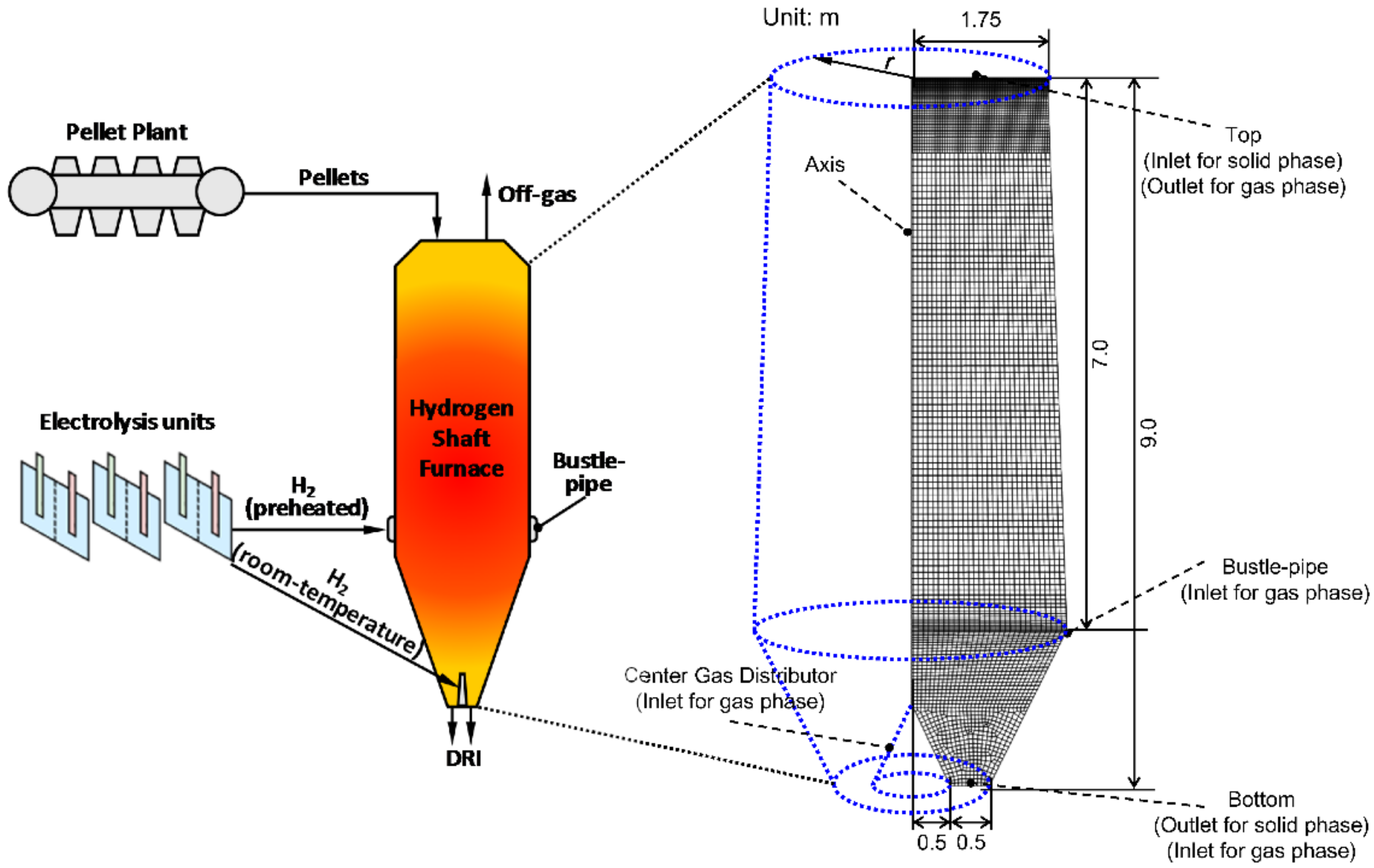
The HSF (equipped with a CGD) is schematically illustrated in (the left of) Figure 1, where the discretized grids required by numerical modeling are presented as well on the right. Within the HSF, the (iron oxide) pellets charged at the top descend and are gradually heated and reduced by the ascending reducing gas that is injected from a bustle-pipe installed at the lower part. As the bottom of the furnace is approached, the pellets are converted into high-metallization DRI, which is subsequently melted and refined into high-quality liquid steel within an electric arc furnace (EAF). It can also be seen that a stream of room-temperature H2 is injected through the CGD located at the furnace bottom.
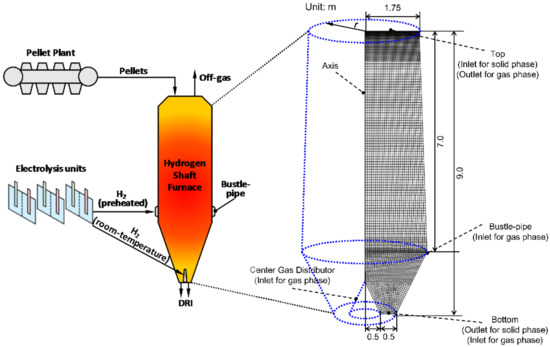
Figure 1.
Schematic of the hydrogen shaft furnace equipped with a center gas distributor and the discretized grids for numerical modeling.
2.1. Basics of Mathematical Model
In order to investigate the intricate gas–solid countercurrent reactive flows in the HSF, a CFD model was developed by the present authors and then employed to clarify how the pellet reducibility and operating pressure affect the overall furnace performance indicators using a one-dimensional domain [19], as well as to evaluate the potential of the operation based on a CGD using a two-dimensional (axisymmetric) domain facilitating a better analysis of the spatial distributions of the field variables [23]. As the continuation of those previous studies, the two-dimensional domain CFD model is utilized in the current paper to further examine how the internal thermochemical state of the HSF responses to variations in the CGD gas feed rate under a scenario where room-temperature H2 is injected through CGD. For the sake of brevity and completeness, this sub-section only outlines the basics of the model, and the reader is referred to [19,23] where detailed model formulae and parameters are well documented.
In general, the two-fluid assumption was applied so that the multi-species gas and solid phases are regarded as interpenetrating continua. Thus, the governing equations expressing the conservation laws (for momentum, heat, and species mass) of each phase can be written in a generalized form as
where ε, ρ, and u are the phasic volume fraction, density, and velocity vector. ϕ and Γ are the to-be-solved field variable and its associated diffusion coefficient. S stands for the source term formulating the interphase exchange of momentum, heat, and mass. In addition, subscript q is the phase under consideration (i.e., gas or solid).
In Equation (1), the source term S takes different values/forms when considering different interphase transport variables. When the variables are related to momentum, heat, and mass, S is formulated based on the vectorial Ergun’s equation, Ranz equation modified by Akiyama and co-authors, as well as the widely adopted unreacted shrinking core model [24,25], respectively. For each species in the two phases, the correlations for estimating temperature-dependent physical properties were obtained by fitting the measured data from reliable sources.
As for key numerical treatment of the current model, the convective and diffusion terms in the left and right of the equality sign of each partial differential equation (cf. Equation (1)) were discretized using a second-order scheme with the intent to achieve a high accuracy. The resulting discretized equations group was then solved iteratively adopting the Gauss–Seidel method where the under-relaxation factors (URFs) were carefully tuned. In particular, URFs were 0.3, 0.5, and 0.3 for the momentum, energy, and species transport equations, respectively. The SIMPLE algorithm was adopted to tackle the coupling of velocity and pressure. The overall convergence was deemed completed when all the relative residuals became less than 1 × 10⁻⁷.
2.2. Boundary Conditions and Model Validation
In the right of Figure 1, the main structure dimensions of the domain and configurations of boundary conditions for the two phases are given explicitly. At the furnace top, the solid phase (i.e., pellets) is charged in with a specific volume flow rate that corresponds to the preset solid mass flow rate while the gas phase flows out under the constraint of a given pressure (i.e., top gas pressure). Through the bustle-pipe in the lower part, the pre-heated feed gas is injected with a specific molar flow rate that corresponds to the preset gas volume flow rate (at standard conditions). The boundary conditions for the gas injected through CGD are similar to those at the bustle-pipe except for the preset temperature. At the furnace bottom, moreover, it is assumed that no gas phase flows out while the solid phase (i.e., DRI) leaves with a volume flow rate identical to that of the solid phase at furnace top. In addition, no-slip, adiabatic, and zero-flux conditions are imposed on the velocity, temperature, and species fraction calculations, respectively, at the remaining boundaries except for the central axis. For the sake of brevity, the mathematical expressions of the boundary conditions are not outlined here, and the reader is referred to [26] for a detailed description.
In order to examine the accuracy of the CFD model, a preliminary simulation was carried out in an earlier work [19] by the present authors to mimic the direct reduction process of iron oxide pellets in a small-scale shaft furnace using pure H2 [27] since measured data of industrial-scale HSF is still absent in the open literature. For the small-scale shaft furnace, the reduction zone length, inner diameter, top gas pressure as well as pellet size are 2.0 m, 0.129 m, 0.116 MPa, and 13.0 mm, respectively. The gas feed rate and temperature are 51.8 Nm3/h and 1180 K, while the pellet mass flow rate and initial temperature and reduction degree are 34.77 kg/h, 298 K, and 0, respectively. In the previous work [19], it has been illustrated that the calculated furnace performance indicators including gas utilization degree, DRI metallization degree as well as top gas temperature are in good agreement with the measured data of the experimental HSF, with the largest relative deviation being less than 3% for the gas utilization degree. This basically confirms the accuracy of the CFD model and thus lends great credibility to the simulation results in the following section. The computational domain and grids for the simulations are shown in the right of Figure 1.
2.3. Parameter Settings
As aforementioned, the main purpose of the current work was to examine how the internal thermochemical state and overall performance indicators of the HSF are affected by the feed rate of CGD gas injected at room temperature. For all the simulation cases of which the results are shown and analyzed in the section that follows, the pellet diameter, mass flow rate, and initial temperature and reduction degree were 13 mm, 100 ton/h, 298 K, and 0, respectively. The top gas pressure was 150 kPa. As for the feed gas (i.e., H2), the total flow rate was fixed at 1500 Nm3/t-pellet. However, the stream blast from the bustle pipe was preheated to 1173 K, while the one through CGD was injected at room temperature (i.e., 298 K). This means the sensible heat of feed gas decreases as the CGD gas feed rate increases. By integrating the temperature-dependent heat capacity of H2 over temperature, the specific sensible heat of the feed gas can be obtained and listed in the last column of Table 1 where the configurations of gas feed rate for the simulation cases studied in this work are also presented. According to a preliminary analysis on grid sensitivity, the two-dimensional axisymmetric computational domain depicted in the right panel of Figure 1 was discretized into 22,000 quadrilateral grids.

Table 1.
Bustle-pipe and CGD gas feed rates and sensible heat of feed gas for each simulation case studied in this work.
3. Results and Discussion
3.1. Feasibility of Room-Temperature CGD Injection
In order to clarify the feasibility of room-temperature CGD injection, some of the predicted results of Case 2 (with a CGD gas feed rate of 50 Nm3/t-pellet) are firstly compared with those of Case 1 where no H2 is injected through CGD. Figure 2 illustrates the gas temperature distributions of the two cases. As can be seen, the gas temperature distributions for the two cases merely differ from each other except for the vertical region in the furnace center where the room-temperature gas stream from the CGD tends to pass through. The temperature is generally higher in the lower part of the furnace and gradually lowers when the gas ascends toward the furnace and reacts with the descending solid particles (i.e., pellets). It therefore follows that the overall in-furnace thermal level marginally changes even though a lower sensible heat is carried by the feed gas, i.e., the sensible heat of feed gas for Case 2 is lower than that for Case 1 by 0.053 GJ/t-pellet. With the intent to further confirm this argument, solid temperature distributions along the furnace bottom for the two cases are shown in Figure 3, where the mass-weighted mean DRI sensible heat is also presented. It is demonstrated that room-temperature CGD injection of Case 2 drastically reduces the solid temperature in the region close to the CGD inlet and the mean DRI sensible heat drops by 0.055 GJ/t-pellet compared to Case 1 where no room-temperature CGD injection is applied. In the countercurrent gas–solid system, strong heat transfer occurs between the hot solid and the CGD gas injected at room-temperature. Thus, the decreased DRI sensible heat is essentially a portion of thermal energy recycled by the CGD gas that eventually delivers the heat into the furnace. Thus, the recycled thermal energy can be calculated as the difference between the sensible heat carried by the discharged DRI under the scenario where no CGD injection operation is applied and the one under the scenario where CGD injection operation is applied. It follows that the total input of sensible heat for Case 2 is 0.002 GJ/t-pellet higher than that for Case 1, hence implying a (slightly) better thermochemical state that facilitates the endothermic reaction of iron oxide reduction by H2 both thermodynamically and kinetically.
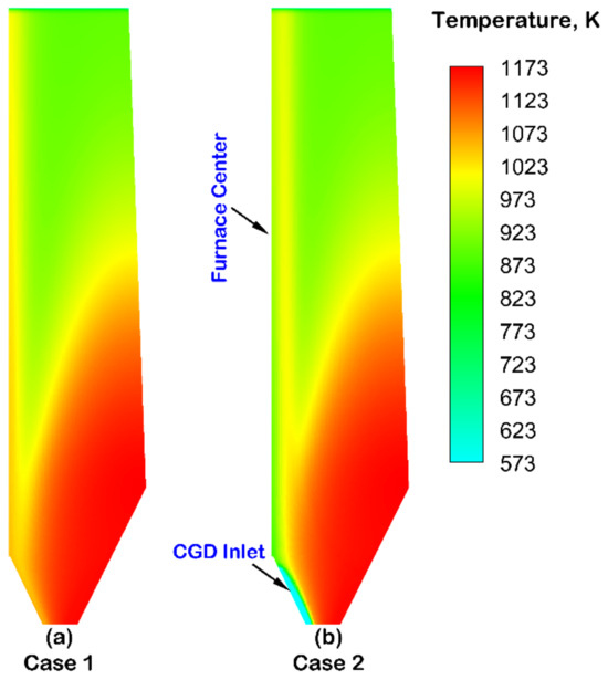
Figure 2.
Distributions of gas temperature under the conditions of Cases 1 and 2.
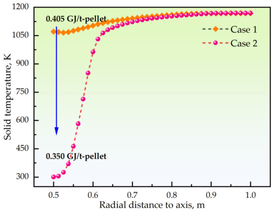
Figure 3.
Distributions of solid temperature along the furnace bottom under the conditions of Cases 1 and 2.
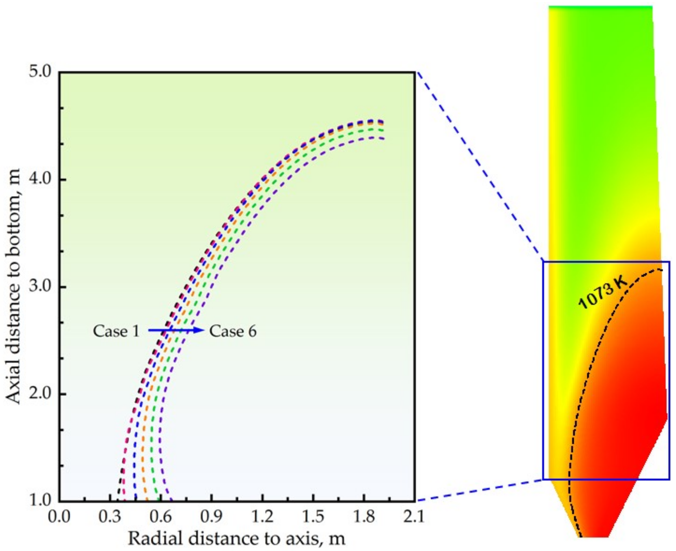
It should be kept in mind that an overly high (room-temperature) CGD feed rate can result in a detrimental scenario where the recycled thermal energy is insufficient to compensate for the decrease of sensible heat of the preheated feed gas from the bustle-pipe. For example, the 1073 K isotherm lines for Cases 1–6 are compared in Figure 4, where it is clearly seen that the curves for Cases 1 and 2 nearly overlap with each other. Nevertheless, the curve tends to shift rightward obviously when the CGD feed rate is increased to 150 Nm3/t-pellet (i.e., for Case 4), indicating a discernable decrease of the in-furnace thermal level. In the following subsection, main efforts are put into illuminating to which extent the CGD feed rate can be increased by investigating how the internal thermochemical state and overall performance indicators of the HSF respond to variations in CGD feed gas.

Figure 4.
Comparisons of 1073 K isotherm lines for Cases 1–6.
3.2. Detailed Analysis
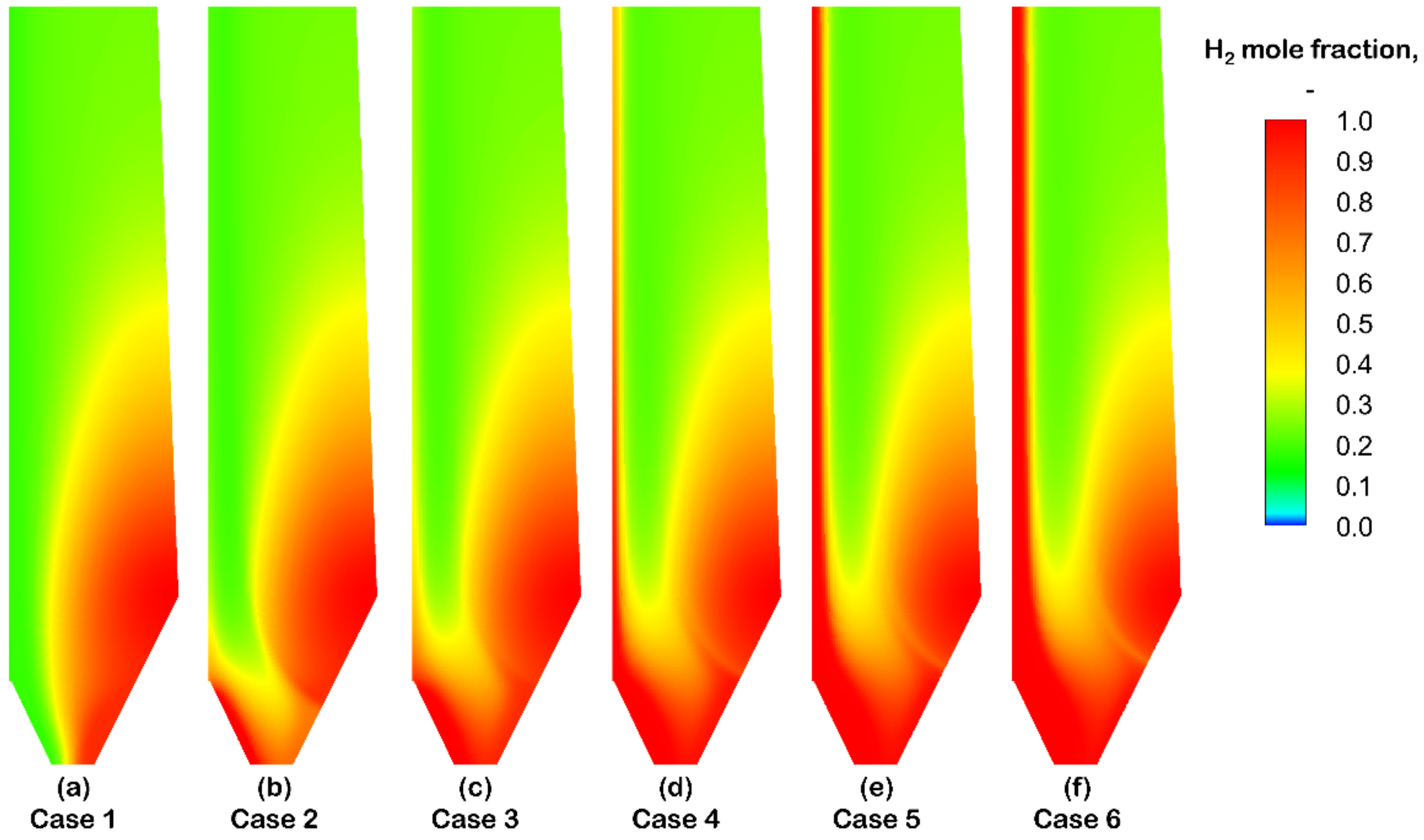
Since H2 is injected through the CGD at room temperature, the in-furnace H2 distribution can provide insight into whether the CGD injection operation could induce a detrimental scenario where the recycled thermal energy is insufficient to compensate for the decrease of sensible heat of the preheated feed gas from the bustle-pipe. For this, the distributions of the H2 mole fraction under the conditions of different CGD feed rates are depicted in Figure 5.
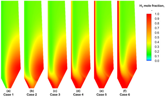
Figure 5.
Distributions of H2 mole fraction under the conditions of different CGD feed rates.
In Figure 5, the mole fraction for Case 1 with no CGD injection decreases as the gas ascends toward the furnace top where the pellets are charged and gradually reduced. The central region of the furnace experiences H2 starvation owing to suppressed local gas velocities attributed to the short penetration distance of the gas stream injected from the bustle-pipe. For Case 2 with a CGD gas feed rate of 50 Nm3/t-pellet, H2 content in the vicinity of CGD becomes high. Since the room-temperature gas is rapidly heated by the hot solid, a high thermal level can be maintained, thus facilitating the endothermic reduction reaction. Consequently, the reducing species is consumed quickly as the local gas flows upward. When the CGD gas feed rate is increased to 100 Nm3/t-pellet (i.e., for Case 3), the center-bottom region with high H2 content is enlarged, and the hot-solid heated reducing species can also be consumed to a great extent before the local gas leaves the furnace from the top. By further increasing the CGD gas feed rate to 150 Nm3/t-pellet or a higher value (i.e., for Cases 4–6), a noteworthy chemical reserve zone of high H2 content tends to form in the furnace center where the thermal level decreases drastically. Consequently, the endothermic reduction reaction is suppressed, and a large quantity of H2 remains unutilized and leaves the furnace from the top.
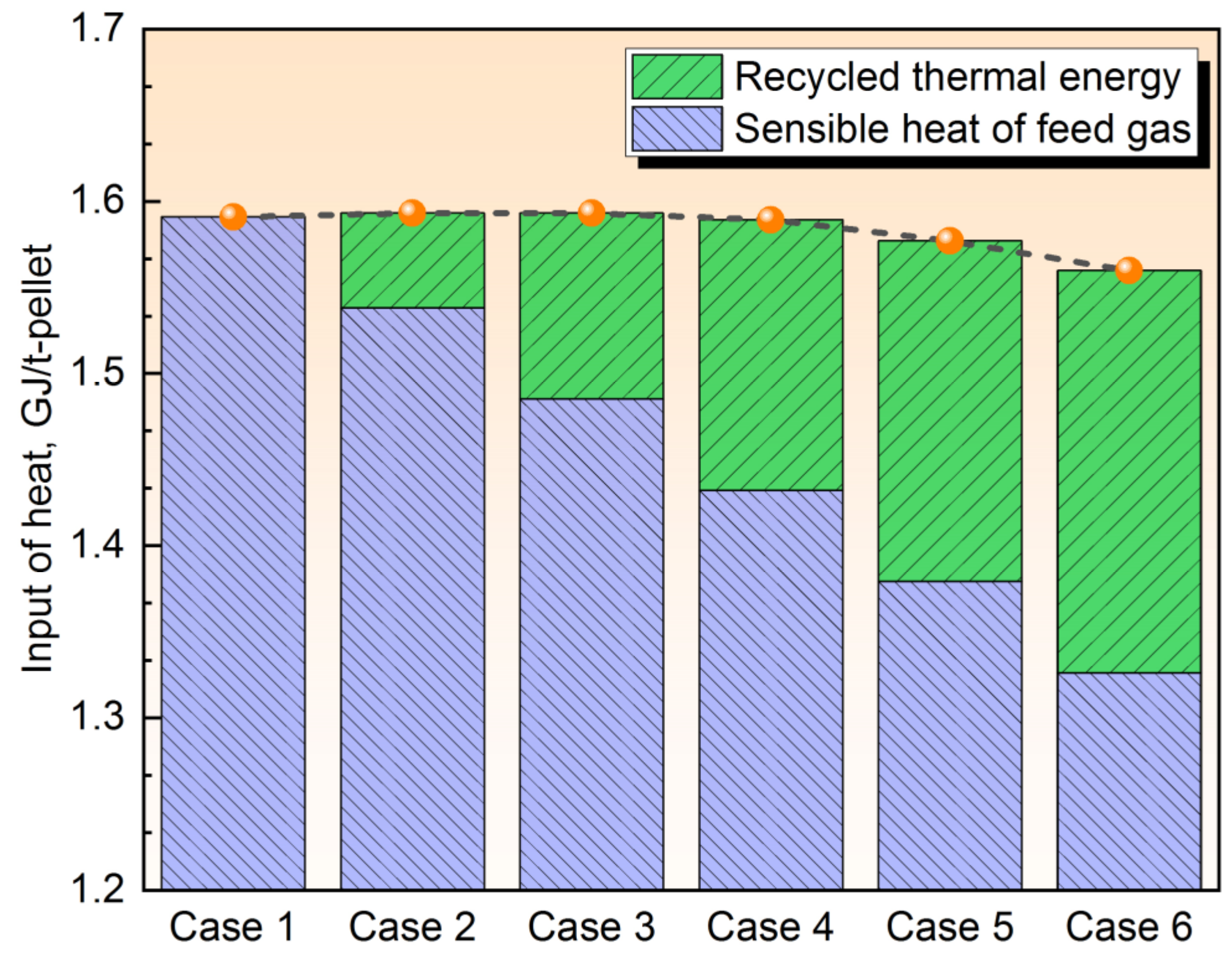
The effect of CGD feed rate on the distribution of solid reduction rate is illustrated in Figure 6, where in panel (a) it can be observed that the reduction rate is high in the semi-oval shaped region surrounding the injection point of the bustle-pipe for Case 1 with no CGD injection. The figure also shows that in the region below the bustle-pipe level, the reduction gradually slows down. This is because the reduction itself comes into the middle-to-late stage for which the required reducing potential for FexO → Fe becomes high. Also, a thick porous shell of Fe surrounding the unreacted shrinking core gives rise to an elevated resistance to mass diffusion of the gas species. In addition, the reduction barely takes place in the furnace center experiencing H2 starvation as aforementioned. For Case 2 with a CGD gas feed rate of 50 Nm3/t-pellet (i.e., for Case 2), however, the reduction in the furnace center is promoted apparently, indicated by the decrease in the volume of blue region where little reduction takes place. This positive effect is retained until the CGD gas feed rate is increased to 150 Nm3/t-pellet for Case 4, where the blue region in the furnace center-bottom tends to expand. In particular, the blue region in the furnace center for Case 6 is seen to be larger than that for Case 1, which indicates that the thermochemical state deteriorates owing to insufficient heat input to the system. This argument is substantiated by Figure 7, where values of recycled thermal energy by CGD gas and sensible heat carried by preheated feed gas under the conditions of different CGD feed rates are shown.
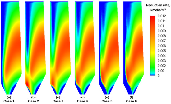
Figure 6.
Reduction rate distributions of solid phase under the conditions of different CGD feed rates.
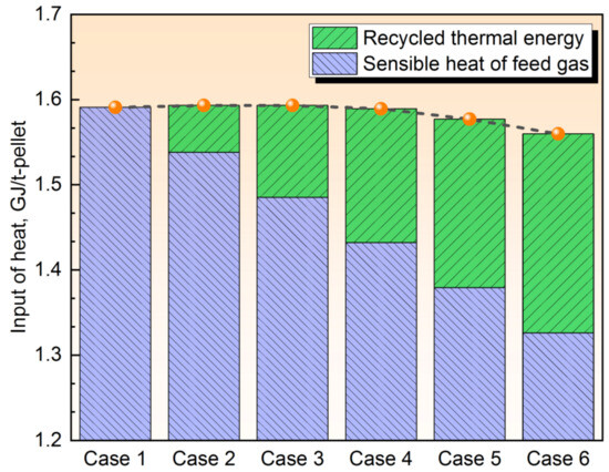
Figure 7.
Values of recycled thermal energy by CGD gas, sensible heat carried by preheated feed gas as well as input of heat (orange circles) under the conditions of different CGD feed rates.
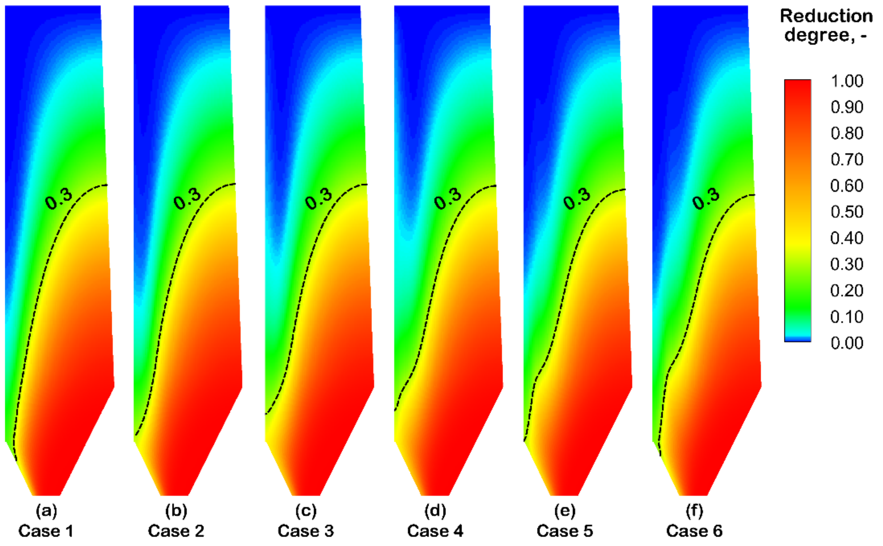
The effect of CGD gas feed rate on reduction degree distribution of the solid phase is demonstrated in Figure 8, where the iso-reduction-degree line of 0.3 for each simulation case is also plotted. As can be observed, the reduction degree becomes higher in the negative vertical direction, although the reduction gradually slows down in the region below the bustle-pipe level as depicted in Figure 6. This is because a decreased reduction rate can still contribute to the increase of reduction degree since more oxygen is removed from the iron oxide. It is worth noticing that the leftmost position of the 0.3 iso-reduction-degree line is lifted when the CGD gas feed rate is increased from 0 to 100 Nm3/t-pellet, i.e., from Case 1 to Case 3. However, the leftmost position tends to drop when the CGD gas feed rate is further increased because of the decrease in total heat input to the system as depicted in Figure 7.
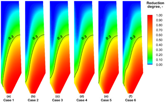
Figure 8.
Reduction degree distributions of solid phase under the conditions of different CGD feed rates.
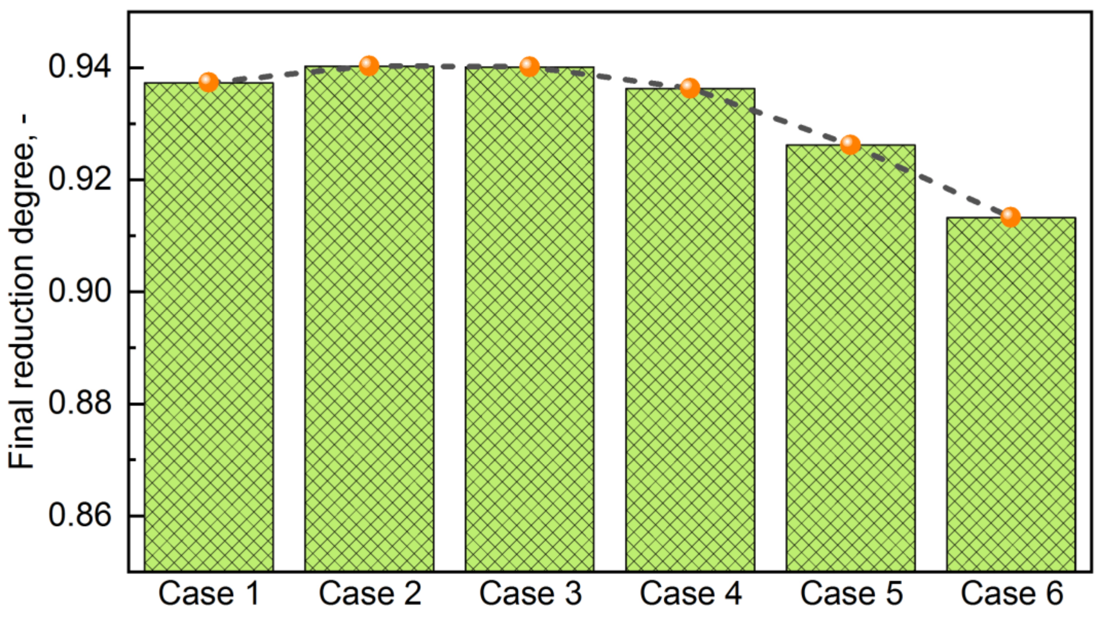
For further assessing the room-temperature CGD injection operation, Figure 9 compares the final (mean) reduction degrees of Cases 1–6, showing compliant variation with the one in Figure 7. As clearly illustrated, the performance indicator rises by increasing the CGD feed rate to 100 Nm3/t-pellet (i.e., for Case 3) and then drops linearly when further increasing the gas feed rate.
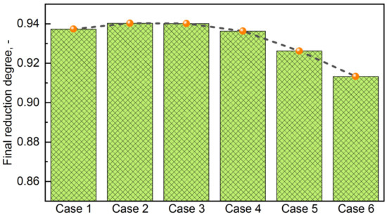
Figure 9.
Final reduction degrees (both light green columns and orange circles) under the conditions of different CGD feed rates.
4. Conclusions and Future Prospects
In the current work, a computational fluid dynamics model based on a detailed description of the intricate gas–solid countercurrent reactive flows was utilized to investigate the performance of the H2 shaft furnace under a scenario where room-temperature H2 is injected through a center gas distributor (CGD) installed at the unit bottom. The results showed that with a proper CGD gas feed rate, a high in-furnace thermal level can be maintained. However, an overly high CGD feed rate (i.e., increasing the CGD gas feed rate to 150 Nm3/t-pellet or a higher value) can induce a detrimental scenario where the recycled thermal energy is insufficient to compensate for the decrease of sensible heat carried by the preheated feed gas from the bustle-pipe, and a noteworthy chemical reserve zone of high H2 content and little solid reduction tends to form in the furnace center. As a result, the endothermic reduction reaction is suppressed and a large quantity of H2 remains unutilized and leaves the furnace from the top. Under the investigated conditions, the final reduction degree of solid rises to maximal value when the CGD gas feed rate is 100 Nm3/t-pellet.
The current work reveals that the room-temperature CGD gas injection operation holds significant promise for practical applications. In the future work, more efforts will be put into carrying out multi-criteria optimization of the overall process based on some practical factors such as pressure drop, particle fluidization, as well as specific energy consumption of metallic iron.
Author Contributions
Conceptualization, L.S.; literature review and original draft preparation, H.Y., C.Z. and L.S.; review and editing, L.S.; funding acquisition, L.S. All authors have read and agreed to the published version of the manuscript.
Funding
This research was funded by the National Science Foundation of China [grant number 52374329] and China Baowu Low Carbon Metallurgy Innovation Foundation [grant number BWLCF202119].
Data Availability Statement
The original contributions presented in the study are included in the article, further inquiries can be directed to the corresponding author.
Conflicts of Interest
The authors declare no conflicts of interest. The funders had no role in the design of the study or interpretation of the results.
References
- Holappa, L. A general vision for reduction of energy consumption and CO2 emissions from the steel industry. Metals 2020, 10, 1117. [Google Scholar] [CrossRef]
- Zhang, X.; Jiao, K.; Zhang, J.; Guo, Z. A review on low carbon emissions projects of steel industry in the world. J. Clean. Prod. 2021, 306, 127259. [Google Scholar] [CrossRef]
- Kim, W.; Sohn, I. Critical challenges facing low carbon steelmaking technology using hydrogen direct reduced iron. Joule 2022, 6, 2228–2232. [Google Scholar] [CrossRef]
- Patisson, F.; Mirgaux, O. Hydrogen ironmaking: How it works. Metals 2020, 10, 922. [Google Scholar] [CrossRef]
- Duarte, P. Trends in hydrogen steelmaking. Steel Times Int. 2020, 44, 35–39. [Google Scholar]
- Rechberger, K.; Spanlang, A.; Conde, A.S.; Wolfmeir, H.; Green, C.H. Hydrogen-based direct reduction for low-carbon steelmaking. Steel Res. Int. 2020, 91, 2000110. [Google Scholar] [CrossRef]
- Pei, M.; Petäjäniemi, M.; Regnell, A.; Wijk, O. Toward a fossil free future with HYBRIT: Development of iron and steelmaking technology in Sweden and Finland. Metals 2020, 10, 972. [Google Scholar] [CrossRef]
- Constantin, A. Nuclear hydrogen projects to support clean energy transition: Updates on international initiatives and IAEA activities. Int. J. Hydrogen Energy 2024, 54, 768–779. [Google Scholar] [CrossRef]
- Vogl, V.; Åhman, M.; Nilsson, L.J. Assessment of hydrogen direct reduction for fossil-free steelmaking. J. Clean. Prod. 2018, 203, 736–745. [Google Scholar] [CrossRef]
- Wang, R.R.; Zhao, Y.Q.; Babich, A.; Senk, D.; Fan, X.Y. Hydrogen direct reduction (H-DR) in steel industry—An overview of challenges and opportunities. J. Clean. Prod. 2021, 329, 129797. [Google Scholar] [CrossRef]
- Pimm, A.J.; Cockerill, T.T.; Gale, W.F. Energy system requirements of fossil-free steelmaking using hydrogen direct reduction. J. Clean. Prod. 2021, 312, 127665. [Google Scholar] [CrossRef]
- Bhaskar, A.; Abhishek, R.; Assadi, M.; Somehesaraei, H.N. Decarbonizing primary steel production: Techno-economic assessment of a hydrogen based green steel production plant in Norway. J. Clean. Prod. 2022, 350, 131339. [Google Scholar] [CrossRef]
- Boretii, A. The perspective of hydrogen direct reduction of iron. J. Clean. Prod. 2023, 429, 139585. [Google Scholar] [CrossRef]
- Sun, M.; Pang, K.; Barati, M.; Meng, X. Hydrogen-based reduction technologies in low-carbon sustainable ironmaking and steelmaking: A review. J. Sust. Metall. 2024, 10, 10–15. [Google Scholar] [CrossRef]
- Parisi, D.R.; Laborde, M.A. Modeling of counter current moving bed gas-solid reactor used in direct reduction of iron ore. Chem. Eng. J. 2004, 104, 35. [Google Scholar] [CrossRef]
- Ghadi, A.Z.; Radfar, N.; Valipour, M.S.; Sohn, H.Y. A review on the modeling of direct reduction of iron oxides in gas-based shaft furnaces. Steel Res. Int. 2023, 94, 2200742. [Google Scholar] [CrossRef]
- Liu, Z.; Lu, S.; Wang, Y.; Zhang, J.; Cheng, Q.; Ma, Y. Study on optimization of reduction temperature of hydrogen-based shaft furnace—Numerical simulation and multi-criteria evaluation. Int. J. Hydrogen Energy 2023, 48, 16132–16142. [Google Scholar] [CrossRef]
- Tian, X.; Zhou, H.; Zhang, Y.; Zhang, T.; Huang, J.; Cai, H.; Kou, M.; Wu, S. Numerical simulation of the influence of operating parameters on the inner characteristics in a hydrogen-enriched shaft furnace. Int. J. Hydrogen Energy 2024, 55, 1131–1142. [Google Scholar] [CrossRef]
- Shao, L.; Wang, Q.; Qu, Y.; Saxén, H.; Zou, Z. A numerical study on the operation of the H2 shaft furnace with top gas recycling. Metall. Trans. B 2020, 52, 451–459. [Google Scholar] [CrossRef]
- Yu, X.; Hu, Z.; Shen, Y. Modeling of hydrogen shaft injection in ironmaking blast furnaces. Fuel 2021, 302, 121092. [Google Scholar] [CrossRef]
- Zhuo, Y.; Hu, Z.; Shen, Y. CFD study of hydrogen injection through tuyeres into ironmaking blast furnaces. Fuel 2021, 302, 120804. [Google Scholar] [CrossRef]
- Zhang, X.; Luo, Z.; Zou, Z. Numerical analysis on performance of COREX CGD shaft furnace with top gas recycling. ISIJ Int. 2019, 59, 1972–1981. [Google Scholar] [CrossRef]
- Yu, S.; Shao, L.; Zou, Z. A numerical study on the process of the H2 shaft furnace equipped with a center gas distributor. Processes 2024, 12, 444. [Google Scholar] [CrossRef]
- Ghadi, A.Z.; Valipour, M.S.; Vahedi, S.M.; Sohn, H.Y. A review on the modeling of gaseous reduction of iron oxide pellets. Steel Res. Int. 2020, 91, 1900270. [Google Scholar] [CrossRef]
- Li, Z.; Qi, Z.; Zhang, L.; Guo, M.; Liang, D.; Dong, Q. Numerical simulation of H2-intensive shaft furnace direct reduction process. J. Clean. Prod. 2023, 409, 137059. [Google Scholar] [CrossRef]
- Ghadi, A.Z.; Valipour, M.S.; Biglari, M. CFD simulation of two-phase gas-particle flow in the Midrex shaft furnace: The effect of twin gas injection system on the performance of the reactor. Int. J. Hydrogen Energy 2017, 42, 103–118. [Google Scholar] [CrossRef]
- Takahashi, R.; Takahashi, Y.; Yagi, J.; Omori, Y. Operation and simulation of pressurized shaft furnace for direct reduction. Trans. Iron Steel Inst. Jpn. 1986, 26, 765–774. [Google Scholar] [CrossRef]


Disclaimer/Publisher’s Note: The statements, opinions and data contained in all publications are solely those of the individual author(s) and contributor(s) and not of MDPI and/or the editor(s). MDPI and/or the editor(s) disclaim responsibility for any injury to people or property resulting from any ideas, methods, instructions or products referred to in the content. |
© 2024 by the authors. Licensee MDPI, Basel, Switzerland. This article is an open access article distributed under the terms and conditions of the Creative Commons Attribution (CC BY) license (https://creativecommons.org/licenses/by/4.0/).