
Improving Shale Stability through the Utilization of Graphene Nanopowder and Modified Polymer-Based Silica Nanocomposite in Water-Based Drilling Fluids
Abstract
:1. Introduction
2. Materials and Methods
2.1. Materials
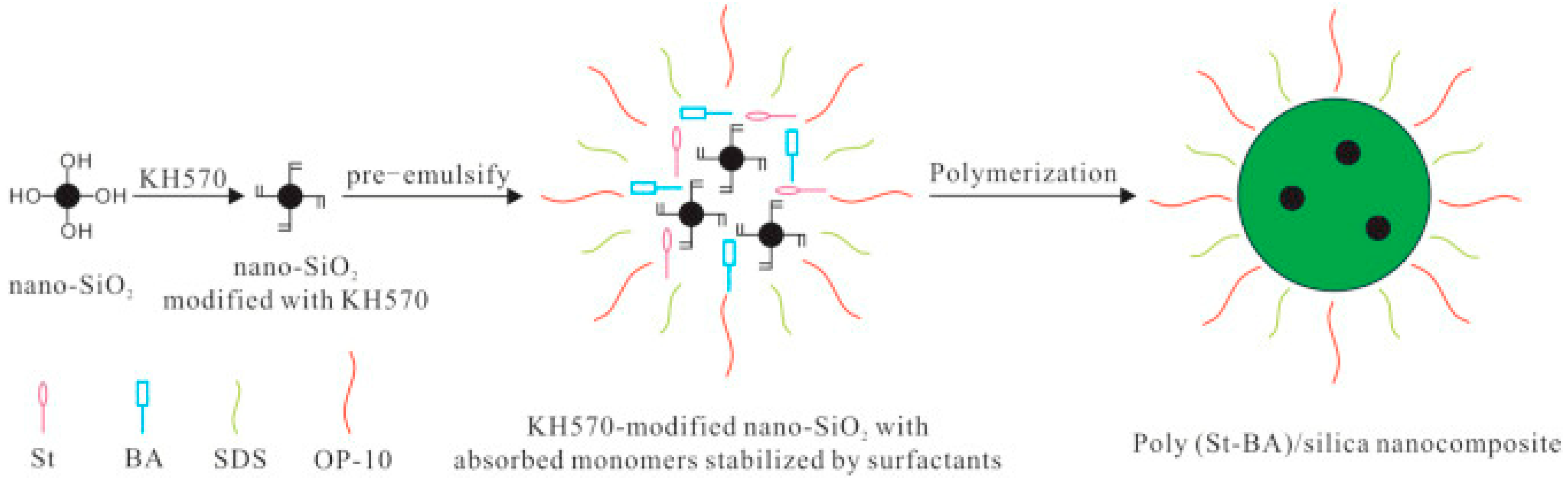
2.2. Preparation of the Silica Nanocomposite
- Dispersion of nanosilica:
- -
- Objective: to ensure uniform dispersion of nanosilica particles.
- -
- Process: nanosilica was dispersed in 100 mL of ethanol using ultrasonic assistance for 1 h.
- -
- Rationale: ethanol was chosen as the solvent due to its ability to effectively disperse nanosilica and prevent agglomeration. The ultrasonic treatment for 1 h ensures a thorough and homogeneous dispersion of nanosilica particles.
- Modification with KH570:
- -
- Objective: to modify the surface of nanosilica for better compatibility with the polymer matrix.
- -
- Process: KH570 was dissolved in the ethanol along with a small amount of water, maintaining a weight ratio of 1:1:18 for KH570/H2O/ethanol. Subsequently, 1 mL of ethylic acid was added to the dispersion and stirred magnetically for 30 min at room temperature.
- -
- Rationale: the specific weight ratio ensures optimal modification conditions. Ethylic acid acts as a catalyst, facilitating the reaction.
- Reaction and stirring:
- -
- Objective: to achieve a thorough modification of nanosilica with KH570.
- -
- Process: the resulting dispersion was transferred to a reaction flask and vigorously stirred for 4 h at 75 °C using a mechanical stirrer.
- -
- Rationale: vigorous stirring at elevated temperature promotes an efficient reaction between KH570 and nanosilica.
- Washing and drying:
- -
- Objective: to remove any unreacted chemicals and solvents from the modified nanosilica.
- -
- Process: the modified nanosilica was washed multiple times with absolute ethanol and dried at 60 °C for subsequent use.
- -
- Rationale: multiple washes with ethanol ensure the removal of residual reactants, and drying at 60 °C prepares the modified nanosilica for the next steps.
- Emulsion polymerization:
- -
- Objective: to prepare the silica nanocomposite as a potential shale stabilizer.
- -
- Process: Emulsion polymerization was conducted using KH570-modified nanosilica, styrene (St), and butyl acrylate (BA). The polymerization process occurred in a 250 mL four-necked flask equipped with a reflux condenser, mechanical stirrer, thermometer, and dropping funnel. Initially, modified nanosilica was dispersed in deionized water containing SDS and OP-10. Subsequently, 0.12 g of NaHCO3, 28 g of styrene (St), and 12 g of butyl acrylate (BA) were added to the dispersion and subjected to ultrasonic treatment for 1 h. The mixture was then pre-emulsified under mechanical stirring and heated to 75 °C for an additional hour. KPS (0.24 g) was added to initiate polymerization, which continued for 3 h at 75 °C before cooling to room temperature.
- -
- Rationale: each component and condition (e.g., NaHCO3, ultrasonic treatment, pre-emulsification, and heating) was carefully selected to ensure the successful formation of a stable nanocomposite with desired properties.
2.3. Characterization and Measurement of Graphene Nanopowder and SiO2-NPs
2.4. Characterization of Silica Nanocomposite
2.5. Preparation of WBDFs
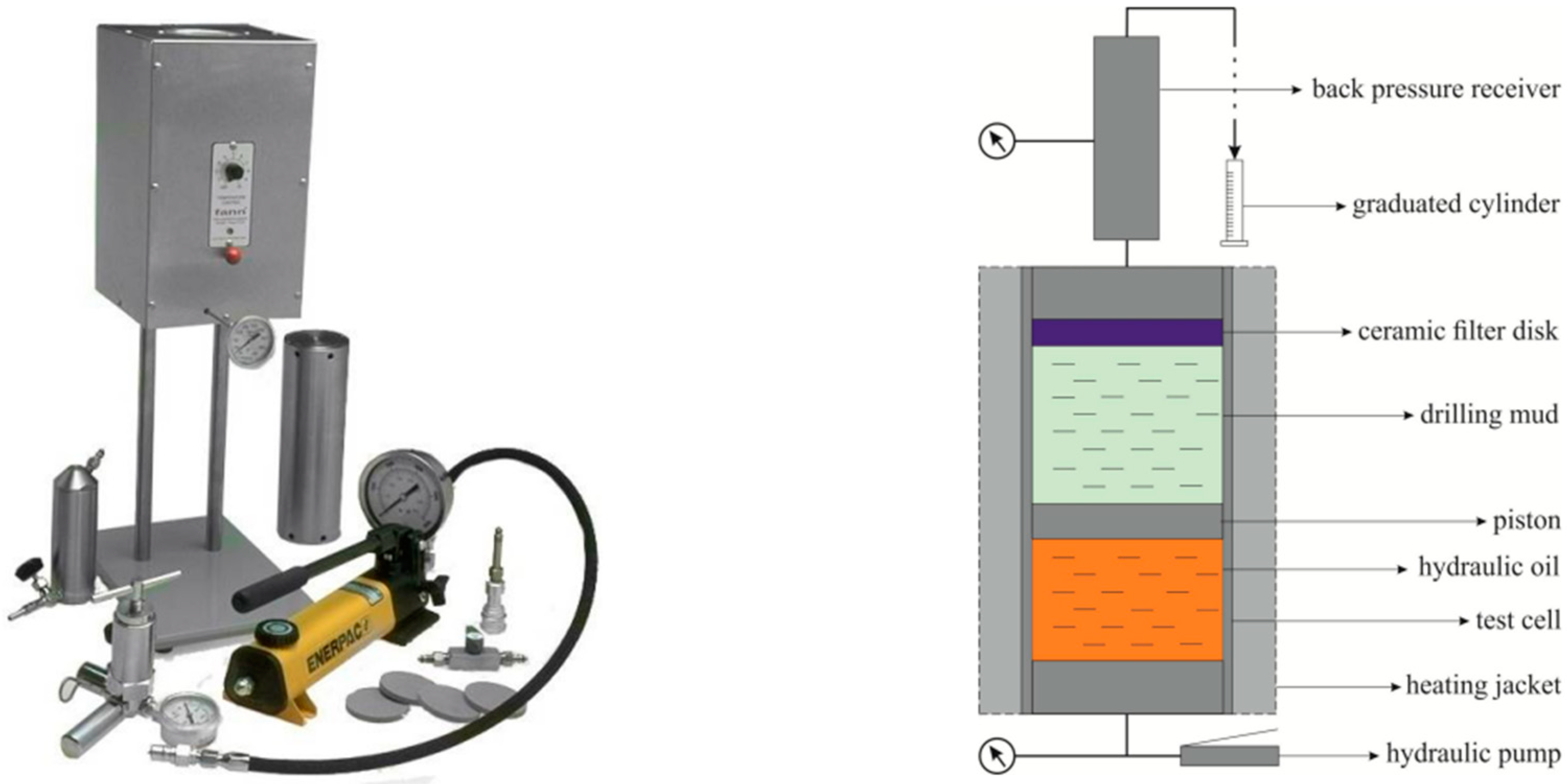
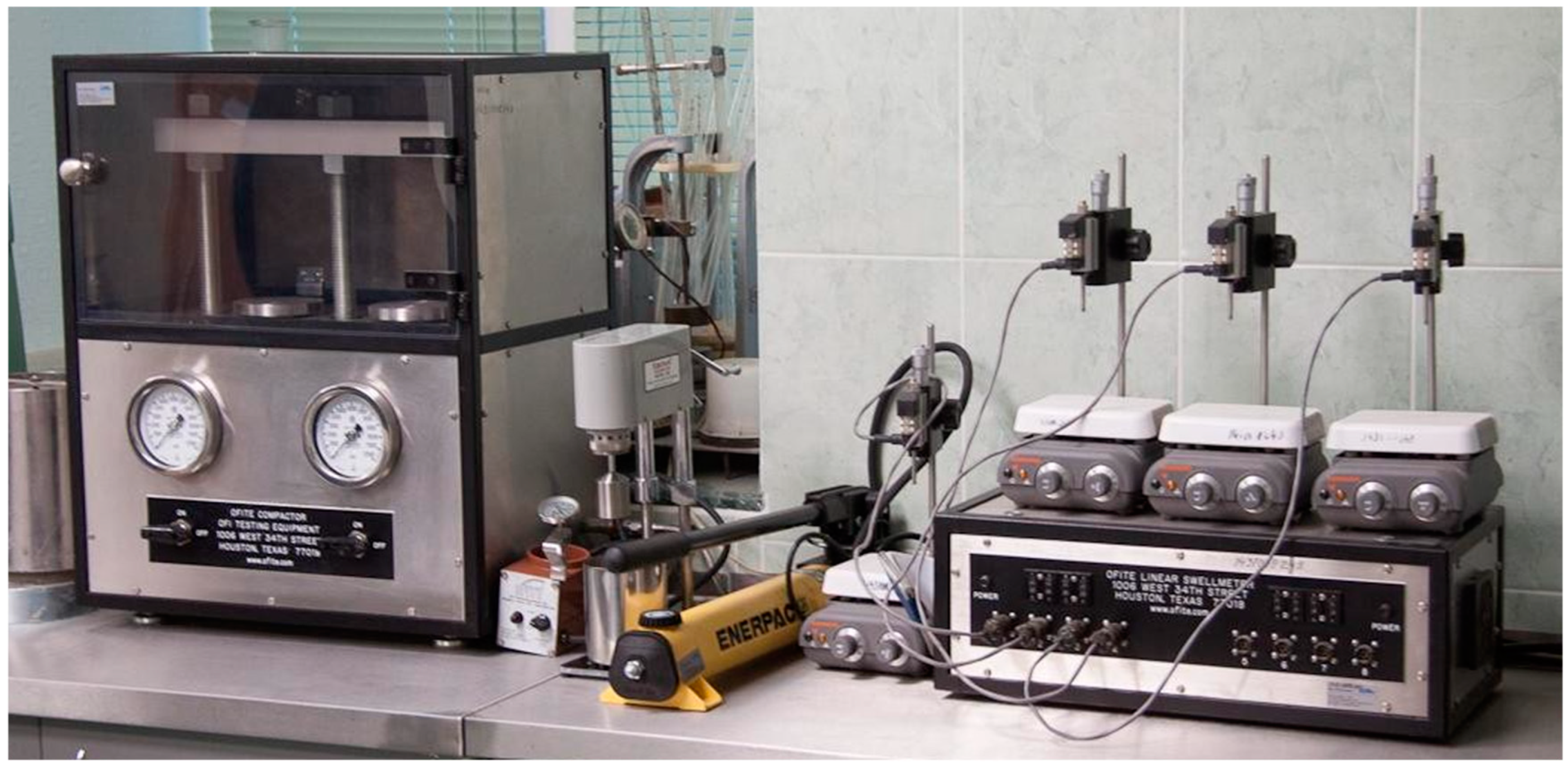
2.6. Drilling Fluid Properties Measurements
- -
- OFITE HTHP filter press (left side): Utilized to measure the fluid loss characteristics of the drilling fluid under high-pressure and high-temperature conditions. This test is essential for evaluating the fluid’s ability to form a filter cake and minimize fluid loss in deep well operations.
- -
- PPA permeability plug apparatus (right side): Employed to assess the fluid’s performance in preventing lost circulation. This device simulates real-world conditions where the drilling fluid needs to seal fractures and porous zones, thereby evaluating the fluid’s effectiveness in mitigating lost circulation issues.
- Clay powder selection:
- -
- The clay powder, primarily composed of montmorillonite, is selected for its high swelling capacity and cation exchange properties.
- Weighing:
- -
- A precise amount of 9.6 g of the unmodified clay powder is weighed using an analytical balance.
- Pressing:
- -
- The weighed clay powder is placed into a mold and pressed at a pressure of 6 MPa using a hydraulic press to form compact clay disks.
- Drying:
- -
- The pressed samples are dried in an oven at 60 °C to remove residual moisture and stabilize the samples.
- Storage:
- -
- The dried clay samples are stored in a desiccator until use to prevent moisture absorption.
- Preparation of the drilling fluids (A, B, C).
- Placement of artificial samples in a container, which was then filled with the fluid.
- Determination of the change in sample volume.
3. Results and Discussion
3.1. Material Characterization
3.2. Characterization of Silica Nanocomposite
3.2.1. FT-IR Analysis
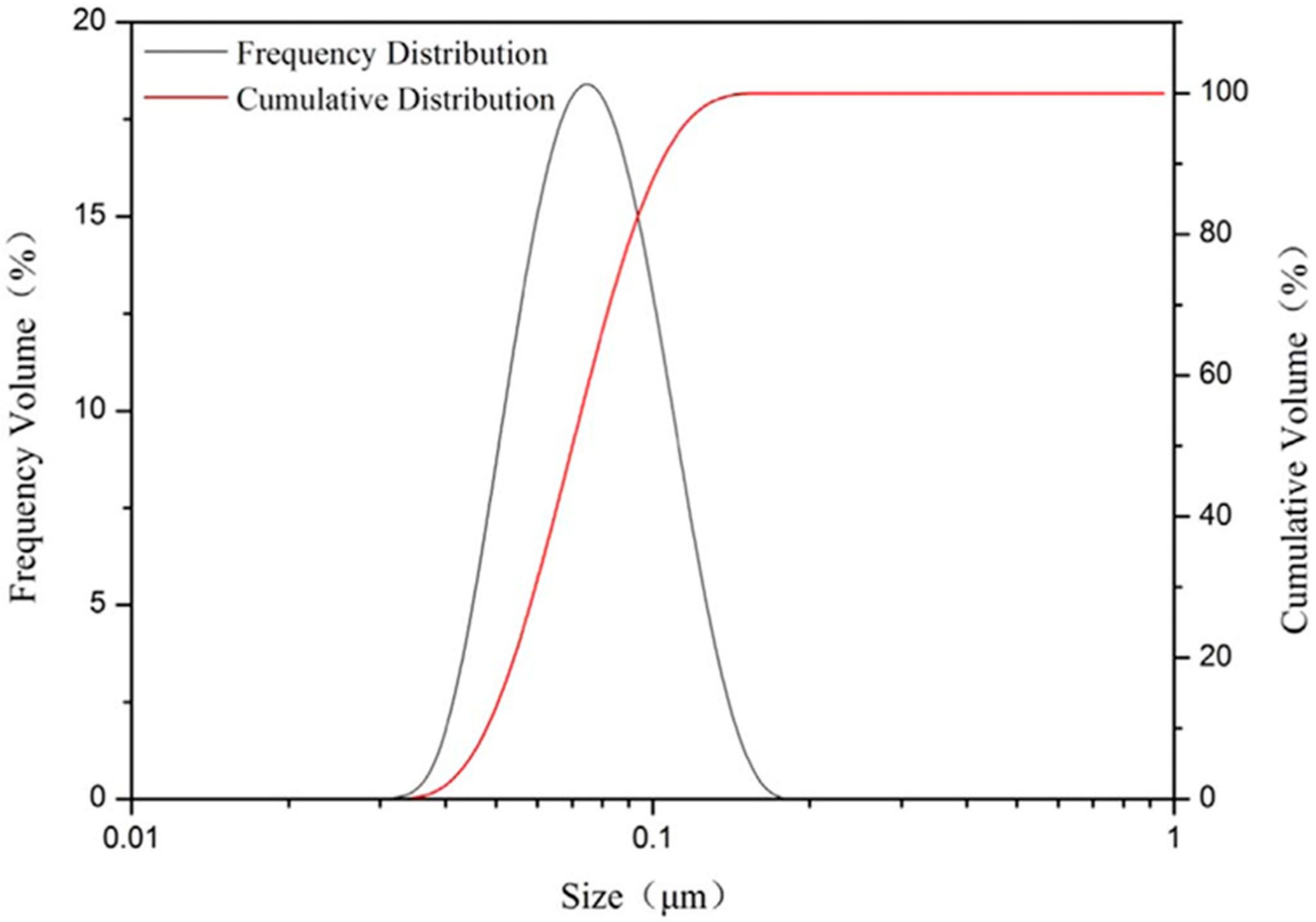
3.2.2. PSD Analysis
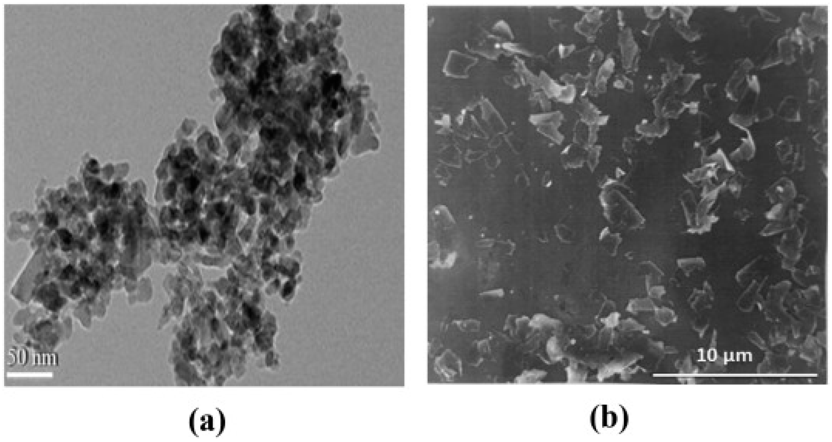
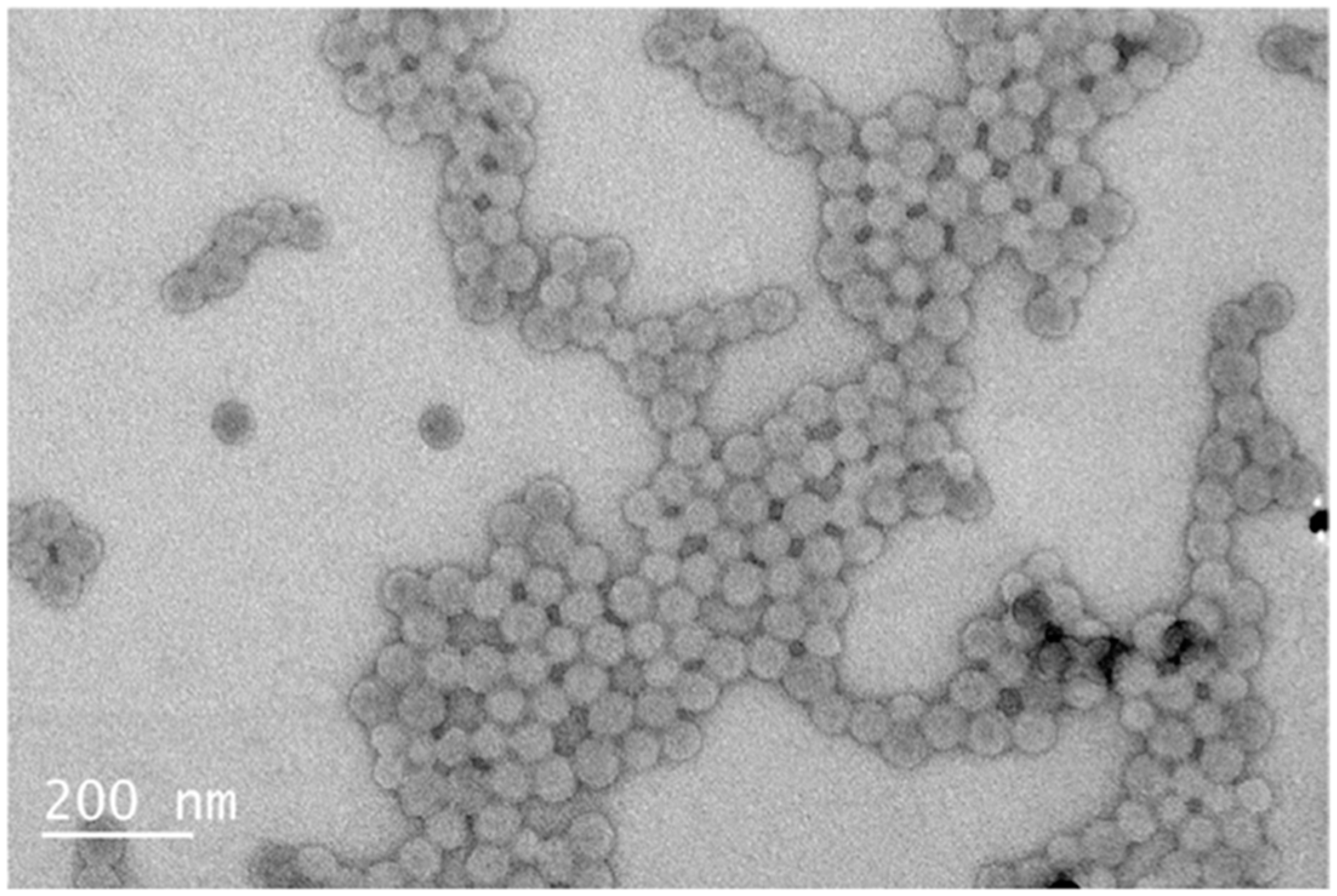
3.2.3. TEM Analysis
3.3. Rheological Properties
3.4. Filtration Properties
3.5. Swelling and Hydration Research Results
4. Conclusions
Author Contributions
Funding
Data Availability Statement
Acknowledgments
Conflicts of Interest
References
- Steiger, R.; Leung, P.K. Quantitative determination of the mechanical properties of shales. SPE Drill. Eng. 1992, 7, 181–185. [Google Scholar] [CrossRef]
- Zhang, S.; Qiu, Z.; Huang, W.; Cao, J.; Luo, X. Characterization of a novel aluminum-based shale stabilizer. J. Pet. Sci. Eng. 2013, 103, 36–40. [Google Scholar] [CrossRef]
- Van Oort, E. On the physical and chemical stability of shales. J. Pet. Sci. Eng. 2003, 38, 213–235. [Google Scholar] [CrossRef]
- Liang, C.; Chen, M.; Jin, Y.; Lu, Y. Wellbore stability model for shale gas reservoir considering the coupling of multi-weakness planes and porous flow. J. Nat. Gas. Sci. Eng. 2014, 21, 364–378. [Google Scholar] [CrossRef]
- Zhou, S.; Xue, H.; Guo, W.; Li, X. A new nuclear magnetic resonance permeability model of shale of Longmaxi Formation in southern Sichuan Basin. J. China Univ. Pet. (Ed. Nat. Sci.) 2016, 40, 56–61. [Google Scholar]
- Akhtarmanesh, S.; Shahrabi, M.A.; Atashnezhad, A. Improvement of wellbore stability in shale using nanoparticles. J. Pet. Sci. Eng. 2013, 112, 290–295. [Google Scholar] [CrossRef]
- Ewy, R.T.; Morton, E.K. Wellbore stability performance of water base mud additives. SPE Drill. Complet. 2009, 24, 390–397. [Google Scholar] [CrossRef]
- Ponmani, S.; Nagarajan, R.; Sangwai, J.S. Effect of nanofluids of CuO and ZnO in polyethylene glycol and polyvinylpyrrolidone on the thermal, electrical, and filtration-loss properties of water-based drilling fluids. SPE J. 2016, 21, 405–415. [Google Scholar] [CrossRef]
- Elmgerbi, A.; Askar, I.A.; Fine, A.; Thonhauser, G.; Ashena, R. Cellulose nanocrystals (CNC’s) as a potential additive for improving API class G cement performance: An experimental study. Nat. Gas Ind. B 2023, 10, 233–244. [Google Scholar] [CrossRef]
- Cao, Y.; Zavaterri, P.; Youngblood, J.; Moon, R.; Weiss, J. The influence of cellulose nanocrystal additions on the performance of cement paste. Cem. Concr. Compos. 2015, 56, 73–83. [Google Scholar] [CrossRef]
- El-Diasty, A.I.; Ragab, A.M.S. Applications of nanotechnology in the oil & gas industry: Latest trends worldwide & future challenges in Egypt. In Proceedings of the North Africa Technical Conference and Exhibition 2013, Cairo, Egypt, 15–17 April 2013; pp. 1–13. [Google Scholar]
- Liu, J.Y.; Qiu, Z.S.; Huang, W.A. Novel latex particles and aluminum complexes as potential shale stabilizers in water-based drilling fluids. J. Pet. Sci. Eng. 2015, 135, 433–441. [Google Scholar] [CrossRef]
- Xu, J.; Qiu, Z.; Huang, W.; Zhao, X. Preparation and performance properties of polymer latex sdnl in water-based drilling fluids for drilling troublesome shale formations. J. Nat. Gas. Sci. Eng. 2017, 37, 462–470. [Google Scholar] [CrossRef]
- Ajayan, P.M.; Schadler, L.S.; Braun, P.V. Nanocomposite Science and Technology; John Wiley & Sons: Hoboken, NJ, USA, 2006. [Google Scholar]
- Zou, H.; Wu, S.; Shen, J. Polymer/silica nanocomposites: Preparation, characterization, properties, and applications. Chem. Rev. 2008, 108, 3893–3957. [Google Scholar] [CrossRef] [PubMed]
- Xu, J.-G.; Qiu, Z.; Zhao, X.; Huang, W. Hydrophobic modified polymer based silica nanocomposite for improving shale stability in water-based drilling fluids. J. Pet. Sci. Eng. 2017, 153, 325–330. [Google Scholar] [CrossRef]
- Aramendis, J.; Imqam, A. Water-based drilling fluid formulation using silica and graphene nanoparticles for unconventional shale applications. J. Pet. Sci. Eng. 2019, 179, 742–749. [Google Scholar] [CrossRef]
- Ji, L.; Guo, Q.; Friedheim, J.; Zhang, R.; Chenevert, M.; Sharma, M. Laboratory evaluation and analysis of physical shale inhibition of an innovative water-based drilling fluid with nanoparticles for drilling unconventional shales. In Proceedings of the SPE Asia Pacific Oil and Gas Conference and Exhibition, Perth, Australia, 22–24 October 2012; pp. 1–12. [Google Scholar]
- Riley, M.; Young, S.; Stamatakis, E.; Guo, Q.; Ji, L.; De Stefano, G.; Friedheim, J. Wellbore stability in unconventional shales—The design of a nano-particle fluid. In Proceedings of the SPE Oil and Gas India Conference and Exhibition, Mumbai, India, 28–30 March 2012. [Google Scholar]
- Deville, J.P.; Fritz, B.; Jarrett, M. Development of water-based drilling fluids customized for shale reservoirs. SPE Drill. Complet. 2011, 26, 484–491. [Google Scholar] [CrossRef]
- Gomez, S.; He, W. Fighting wellbore instability: Customizing drilling fluids based on laboratory studies of shale-fluid interactions. In Proceedings of the IADC/SPE Asia Pacific Drilling Technology Conference and Exhibition, Tianjin, China, 9–11 July 2012. [Google Scholar]
- Salih, A.H.; Elshehabi, T.A.; Bilgesu, H.I. Impact of nanomaterials on the rheological and filtration properties of water-based drilling fluids. In Proceedings of the SPE Eastern Regional Meeting 2016, Canton, OH, USA, 13–15 September 2016. [Google Scholar]


| Concentration (lbm/bbl) | 1.0 | 10 | 0.25 | 1.85 | 1.85 | * |
|---|---|---|---|---|---|---|
| Additive | Water | Bentonite | Xhantan | Starch | PAC-LV | KOH |
| WBDF + the silica nanocomposite (B) | 675 mL basic WBDF + 2 wt% NFC |
| WBDF + the graphene nanopowder (C) | 675 mL basic WBDF + 0.5 wt% graphene nanopowder |
| Fluid | Rheological Properties at 120 0F and 14.7 psi | LTLP Fluid Loss (mL/30 min) | HTHP Fluid Loss (mL/30 min) | ||||
|---|---|---|---|---|---|---|---|
| PV (cP) | YP (lbf/100 ft2) | Gel10s (lbf/100 ft2) | Gel10min (lbf/100 ft2) | Gel30min (lbf/100 ft2) | |||
| A | 19 | 15 | 3 | 9 | 12 | 8.6 | 27.2 |
| B | 16 | 20 | 4 | 14 | 19 | 7.2 | 20.2 |
| C | 17 | 19 | 4 | 14 | 19 | 7.5 | 21 |
| Fluid | Swelling Intensity % at 1 h, 2 h, 3 h, 12 h, 24 h | ||||
|---|---|---|---|---|---|
| 1 h | 2 h | 3 h | 12 h | 24 h | |
| The base fluid (A) | 11 | 13 | 15 | 20 | 25 |
| The silica nanocomposite WBDF (B) | 8 | 7.9 | 7.9 | 8 | 8 |
| The graphene nanopowder WBDF (C) | 9 | 10 | 11 | 12 | 12 |
Disclaimer/Publisher’s Note: The statements, opinions and data contained in all publications are solely those of the individual author(s) and contributor(s) and not of MDPI and/or the editor(s). MDPI and/or the editor(s) disclaim responsibility for any injury to people or property resulting from any ideas, methods, instructions or products referred to in the content. |
© 2024 by the authors. Licensee MDPI, Basel, Switzerland. This article is an open access article distributed under the terms and conditions of the Creative Commons Attribution (CC BY) license (https://creativecommons.org/licenses/by/4.0/).
Share and Cite
Ospanov, Y.K.; Kudaikulova, G.A.; Moldabekov, M.S.; Zhaksylykova, M.Z. Improving Shale Stability through the Utilization of Graphene Nanopowder and Modified Polymer-Based Silica Nanocomposite in Water-Based Drilling Fluids. Processes 2024, 12, 1676. https://doi.org/10.3390/pr12081676
Ospanov YK, Kudaikulova GA, Moldabekov MS, Zhaksylykova MZ. Improving Shale Stability through the Utilization of Graphene Nanopowder and Modified Polymer-Based Silica Nanocomposite in Water-Based Drilling Fluids. Processes. 2024; 12(8):1676. https://doi.org/10.3390/pr12081676
Chicago/Turabian StyleOspanov, Yerlan Kanatovich, Gulzhan Abdullaevna Kudaikulova, Murat Smanovich Moldabekov, and Moldir Zhumabaevna Zhaksylykova. 2024. "Improving Shale Stability through the Utilization of Graphene Nanopowder and Modified Polymer-Based Silica Nanocomposite in Water-Based Drilling Fluids" Processes 12, no. 8: 1676. https://doi.org/10.3390/pr12081676