Article

Sensitivity Analysis of Injection Mass Flow to the Inlet Orifice Radius of a GDI Injector Nozzle

1
School of Mechanical and Electronic Engineering, Shandong Jianzhu University, Jinan 250101, China
2
Binzhou Polytechnic, Binzhou 256603, China
*
Author to whom correspondence should be addressed.
Processes 2024, 12(8), 1740; https://doi.org/10.3390/pr12081740
Submission received: 25 May 2024 / Revised: 8 August 2024 / Accepted: 12 August 2024 / Published: 19 August 2024
(This article belongs to the Section Energy Systems)

Abstract

:
It is more difficult to accurately control the cycle fuel mass of a gasoline engine as the injection pressure increases, and the difference in the injection mass flow will become intense due to the machining error of GDI injector structural parameters. In order to guarantee the uniform cycle fuel mass of the GDI injector, this paper investigates the effect of the inlet orifice on the injection mass flow and the sensitivity of inner-flow characteristics in the GDI injector nozzle to the inlet orifice radius by the single factor analysis method. The results show that the local resistance of the injector nozzle will decrease and the discharge coefficient will rise due to the increase in the inlet orifice radius; the sensitivity of cycle fuel mass to the inlet orifice radius is most strong at r = 0.02 mm, and its accuracy should be improved when grinding the chamfer of the nozzle inlet; the sensitivity coefficient of the inlet orifice radius will rise up, and the machining accuracy of the inlet orifice radius should be improved as there is an increase in injection pressure.

1. Introduction

The current harsh emission regulations promote the continuous innovation of engine technology. GDI (gasoline direct injection) coupled with high turbo-charge has an important impact on engine economy and emission characteristics [1,2]. As a key component of the gasoline direct injection fuel system, the characteristic of the injector directly affect the fuel injection rate and the fuel distribution in the cylinder; thus, it affects the combustion and emission performance of the GDI gasoline engine. The flow in the GDI injector nozzle is a complicated multiphase flow process because of the phenomena of cavitation and turbulence. To meet the stringent emission regulations, the combustion system, strong turbulence and high compression ratio have great development potential. It will be more difficult to control accurately the cycle fuel mass due to the increase in injection pressure. With the increase in fuel injection pressure, the processing error of the structure parameter of the fuel injector will cause the difference in cycle injection fuel mass between holes and products to increase. Therefore, it is necessary to study and analyze the influence of processing errors of GDI injector structural parameters on injection characteristics so as to ensure the consistency of circulating injection quantity under high pressure injection.
A great deal of research work has been carried out on the multiphase flow in the nozzle and the spray characteristics of a GDI injector. At present, the minimum diameter of a GDI injector nozzle can reach 80 microns. It is difficult to directly analyze the real flow characteristics of the nozzle through experiments. Researchers designed the enlarged transparent injector nozzle [3,4] and built a visual platform to analyze the inception and development of cavitations in the nozzle based on the similarity criterion. The results could be used to validate the multiphase flow simulation model, but it is difficult to analyze the effect of a change in nozzle structure on the flow characteristic. Also, high-speed camera technology was used to take pictures of the spray pattern of the fuel injector under the conditions of supercooling, transition and flashing [5]. In addition, the researchers revealed the variation in multiphase flow in the GDI injector by means of simulation analysis and described the inception and development of cavitation in the GDI injector nozzle [6] using volume of fluid [7,8] and nonlinear cavitation models [9]. The effect of the nozzle structural parameter [10] on the development process of internal cavitation was also studied. It was pointed out that the inlet orifice radius of the nozzle was beneficial to reduce cavitation and increase the spray penetration distance. The nozzle length to diameter ratio had little effect on cavitation and spray cone angle, but the increase in the nozzle cone would reduce the penetration distance. Other researchers studied inner nozzle flow based on visual tests and simulation; the effect of some factors, including injection pressure, back pressure, fuel temperature, injector nozzle distribution, injector needle moving and the nozzle types on the spray droplet, spray angle and the tip penetration distance, were also studied [11]. Qing et al. [12] studied the change in flashing spray under different injection pressures in a gasoline engine, and the results showed that the increase in injection pressure induced the enhancement of overheating and led to finer droplets. Sanghoon et al. [13] used visual methods to compare the spray characteristics of GDI injectors with single-hole and group-hole configurations. The interaction of jet kinetic energy between holes led to smaller atomized droplet diameters and improved atomization performance. Li [14] proposed the variation in fuel injection quantity caused by the difference in structural parameters between spray holes and proposed a method for optimizing structural parameters to improve it. Li [15] proposed to evaluate the relationship between the structural parameters of fuel injectors and their performance through sensitivity coefficients. It was deemed that the increase in injection pressure could reduce the Sauter diameter of the particles, increase the spray area and improve the atomization characteristics.
On the basis of previous studies, the influence of the inlet orifice radius of the GDI injector nozzle on cycle injection fuel mass is analyzed by simulation. This article proposes the use of sensitivity analysis to study the structural parameters of fuel injector nozzle holes and proposes a quantitative analysis method for the machining accuracy range, which can obtain the structural parameter range that meets product requirements.

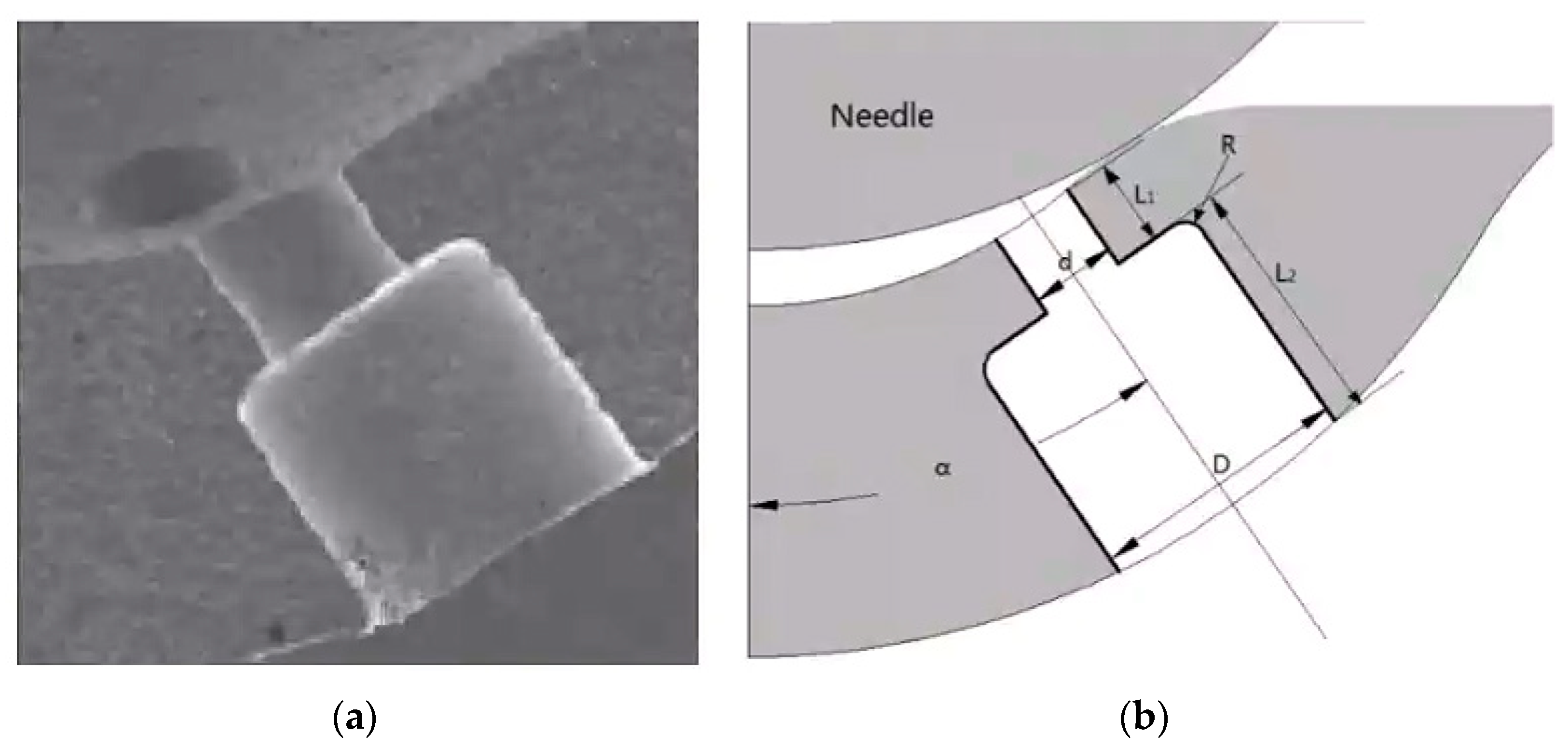
2. Object Description and Validation

When the fuel passes through the fillet of the nozzle inlet, where the flow direction inside the injector nozzle changes dramatically, there will form a low pressure area at the hole entrance. Bubbles will be generated when the local pressure is lower than the saturated steam pressure, which is called the cavitation phenomenon. To describe the flow in the nozzle, the mathematical models, including the turbulence model, the Euler model and the Rayleigh equation, are considered [16].
(1)
Cavitation model
The nonlinear cavitation model takes into account all the terms in the Rayleigh equation. The bubble radius R time derivative is expressed using the Rayleigh equation as
R = 2 3 ( Δ p ρ c R R )
Δ p is the effective pressure difference between inlet and outlet, and ρ c is the density. Then the interfacial mass exchange term becomes
Γ c = ρ d N 4 π R 2 R = Γ d
N is bubble number density, and Γ c and Γ d represent the interfacial mass exchange between liquid and gas.
In order to study the sensitivity of flow characteristics in the nozzle and near injection orifice to the inlet chamfering radius of the GDI injector nozzle, the modeling of the GDI injector nozzle is carried out. Figure 1a displays the object of the GDI injector nozzle [6,17], and Figure 1b shows the detailed structure parameters of the GDI nozzle called “Spray G”. Due to the six-hole axisymmetric structure of the injector, in order to improve the computational efficiency, a one-sixth three-dimensional model is established, and the fluid domain model is abstracted, including pressure inlet boundary, pressure outlet boundary and symmetry. The inlet orifice area is also refined; as shown in Figure 2, the inlet orifice radius is 0.00, 0.01, 0.02, 0.03, 0.04 and 0.05 mm. The detailed nozzle sizes, fuel properties and boundary conditions are displayed in Table 1.
To validate the effectiveness of the mathematical model, a magnified nozzle is used to explore the cavitation phenomena on a fuel pump test bench [3,16]. The pictures of the gas–liquid in the nozzle are captured, and the mass flow under different pressures is measured. The simulation results are compared with the experiment data, and the effect of the mesh number on simulation results is studied [18]. Therefore, the mathematical models are reliable.

3. Results and Discussion

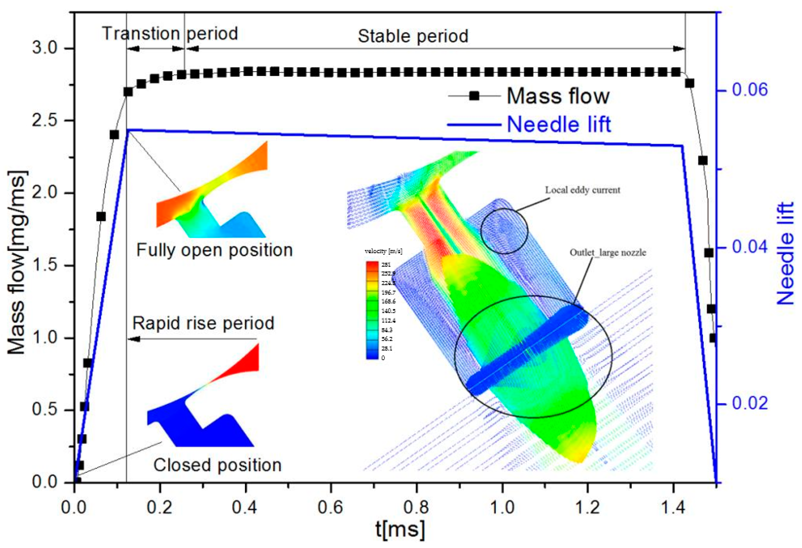
3.1. The Injection Process of the Injector Nozzle Called “Spray G”

The following assumptions are made in the initial conditions in the simulation process: firstly, the pressure distribution is zoned. The gap between the needle valve and the needle valve seat is used to divide into high pressure area and low pressure area, as shown in Figure 3a. When the needle valve moves up, the high-pressure fuel flows from top to bottom, and the pressure distribution in the nozzle changes. Secondly, the initial distribution of the gas–liquid fuel is assumed. Because the small nozzle diameter is 0.15 mm and the large nozzle diameter is 0.45 mm, it is considered that the residual fuel in the large nozzle has been completely eliminated. Therefore, the interface between large and small nozzles acts as a boundary between the gas and liquid phases. The small nozzle is considered to be filled with liquid fuel, while the large holes and the near-nozzle are considered to be filled with air. Simulation of flow characteristics in the nozzle of the “Spray G” injector with movement of the injector needle is carried out based on the above assumptions.
Figure 4 shows the injection rate changes with the needle movement and the needle lift curve; the injection pressure is 35 MPa, the injection back pressure is 0.5 MPa and the nozzle inlet chamfer is 0.02 mm. As can be seen from the diagram, the gap between the needle valve and the needle seat is minimal at the initial moment, and it can be considered completely closed. When the needle valve is fully open, the distance between the needle valve and the needle seat causes a difference in the pressure distribution between the upper and lower parts. To facilitate analysis, the injection process could be divided into three stages: the rapid rise period, the period of transition period and the stable period according to the change in injection rate. In the rapid rise period, the injection rate rises sharply with the opening of the injector needle. It is due to the rapid increase in the minimum flow cross-section area caused by the opening of the needle valve and the large pressure difference between the high-pressure fuel area and the low-pressure fuel area. When the needle valve is fully opened, the fuel injection rate gradually slows down and tends to be stable; this process is defined as a transition period. During the stable period, although the maximum lift of the needle valve decreased slightly, the injection rate is still stable because the minimum flow section is still located at the nozzle region at this time. Finally, with the closing of the needle valve, the minimum flow section area decreases and the injection rate drops rapidly until the needle valve is completely closed. Due to the limitation of calculation time domain, at the moment when the needle valve is completely closed, there is still a part of residual pressure in the fuel chamber of the nozzle, so the injection rate is not zero. To analyze the internal flow process of the “Spray G” nozzle, the injection velocity vector diagram of steady state period is also given in the graph. The velocity vector at the outlet of the large nozzle is larger, and the edge velocity direction of the large nozzle is in the opposite direction. Local eddy currents appear in the shoulder region of the large nozzle, and the local eddy currents can promote the mixing of fuel and air at the edge of the liquid fuel jet, thus promoting the atomization performance outside the nozzle.

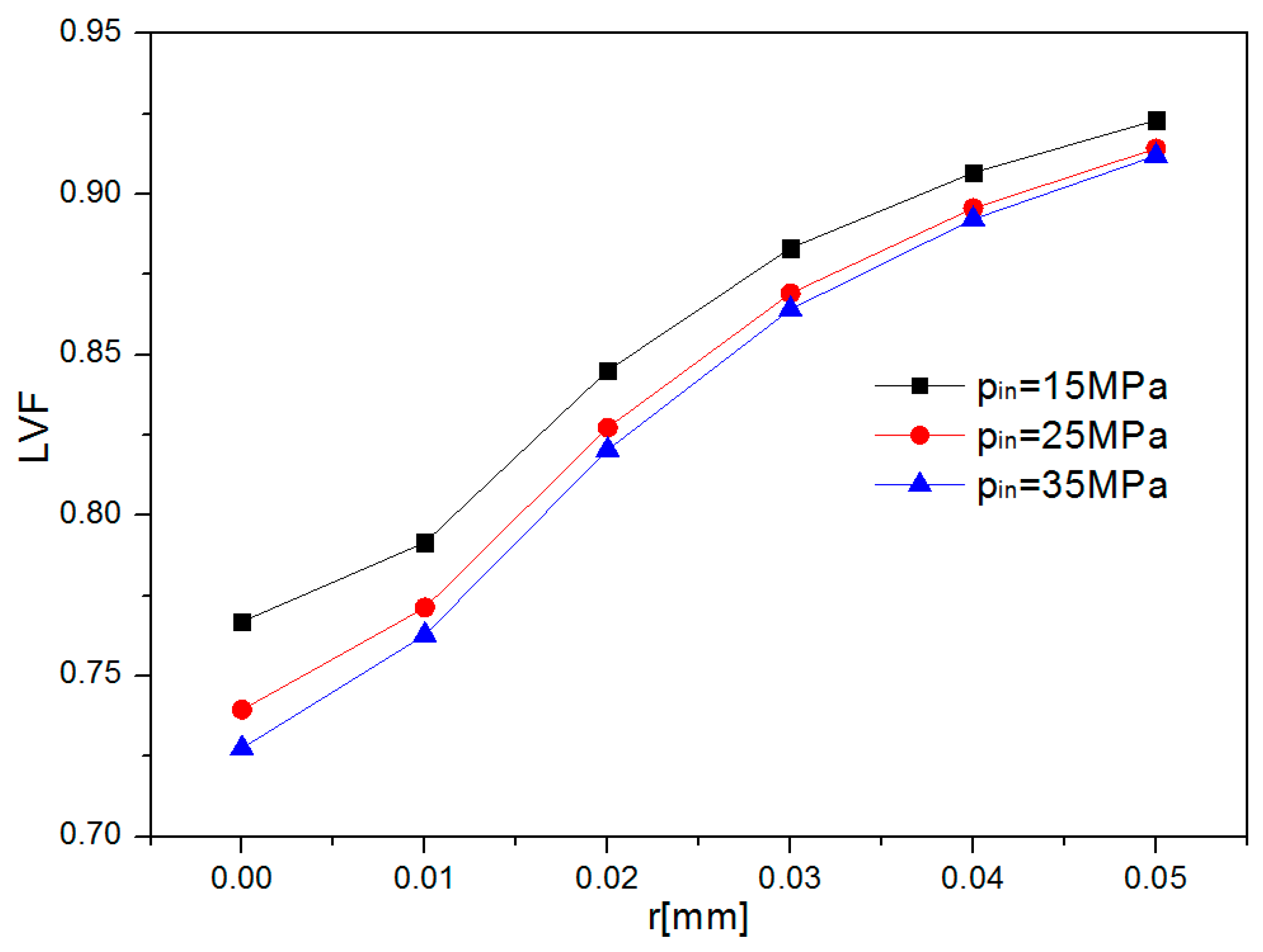
3.2. The Effect of Inlet Orifice Radius of the GDI Injector on the Injection Characteristic

The injection characteristic curves at different entrance radii of nozzles are shown in Figure 5. The injection pressure is 35 MPa, and the back pressure is 0.5 MPa. It is seen that the injection rate rises rapidly and then stabilizes with the opening of the injector needle. To facilitate analysis, the injection process could be divided into three stages: the rapid increase period, the period of transition period and the stable period according to the change in injection rate. During the rapid increase period, the variation trend of injection rate under different inlet orifice radii is consistent. In the transition period, the injection rate increases first and then decreases to a stable stage when r ≤ 0.01 mm; however, the injection rate rises slowly and then enters a stable stage when r ≥ 0.02 mm. The analysis shows that with the increase in the injector needle, the position of the minimum flow cross-section area of fuel injection has changed from the needle moving area to the nozzle area. A smaller inlet orifice radius will lead to the sudden change in flow section; the cavitation occurs when high-speed fuel flows through the inlet and extends along the inner wall of the nozzle to the outlet, resulting in a decrease in the effective flow cross-section area. Therefore, the injection rate decreases and tends to stabilize. However, with the increase in chamfer radius, the fuel flows along the corner wall, the flow section gradually decreases, the local resistance coefficient decreases and the injection rate increases slowly. During the stable period, the injection rate increases with the increase in the inlet orifice radius.
Figure 6 displays the injection rate and the effective flow cross-section of the small nozzle outlet.
It could be seen that the increase in the inlet orifice radius will lead to an increase in the effective flow cross-section of the small nozzle outlet, and then the injection rate rises. At the same time, the cut-planes of velocity vector at r = 0.00, 0.01 and 0.02 mm of nozzle inlet area are shown in the figure. As can be seen from the velocity vector diagram, there is a local small eddy current on the upper inner wall near the entrance of the nozzle at r = 0. 00 mm. When r = 0.01 mm, the eddy current decreases and the velocity vector is gradually oriented towards the nozzle outlet. When r = 0.02 mm, the local small eddy current disappears, the chamfer radius continues to increase and the velocity direction is towards the nozzle outlet along the inner wall of the nozzle. The relationship between flow coefficient and resistant coefficient could be expressed as
C d = 1 / 1 + ξ
h l = ρ υ 2 ξ / 2 = Δ p ξ
where ξ is the resistant coefficient and h l is the local resistance [19].
According to Formulas (3) and (4), with the increase in the inlet orifice radius, the local resistance coefficient decreases, thus reducing the local resistance of the flow in the nozzle. As a result, the flow coefficient increases.

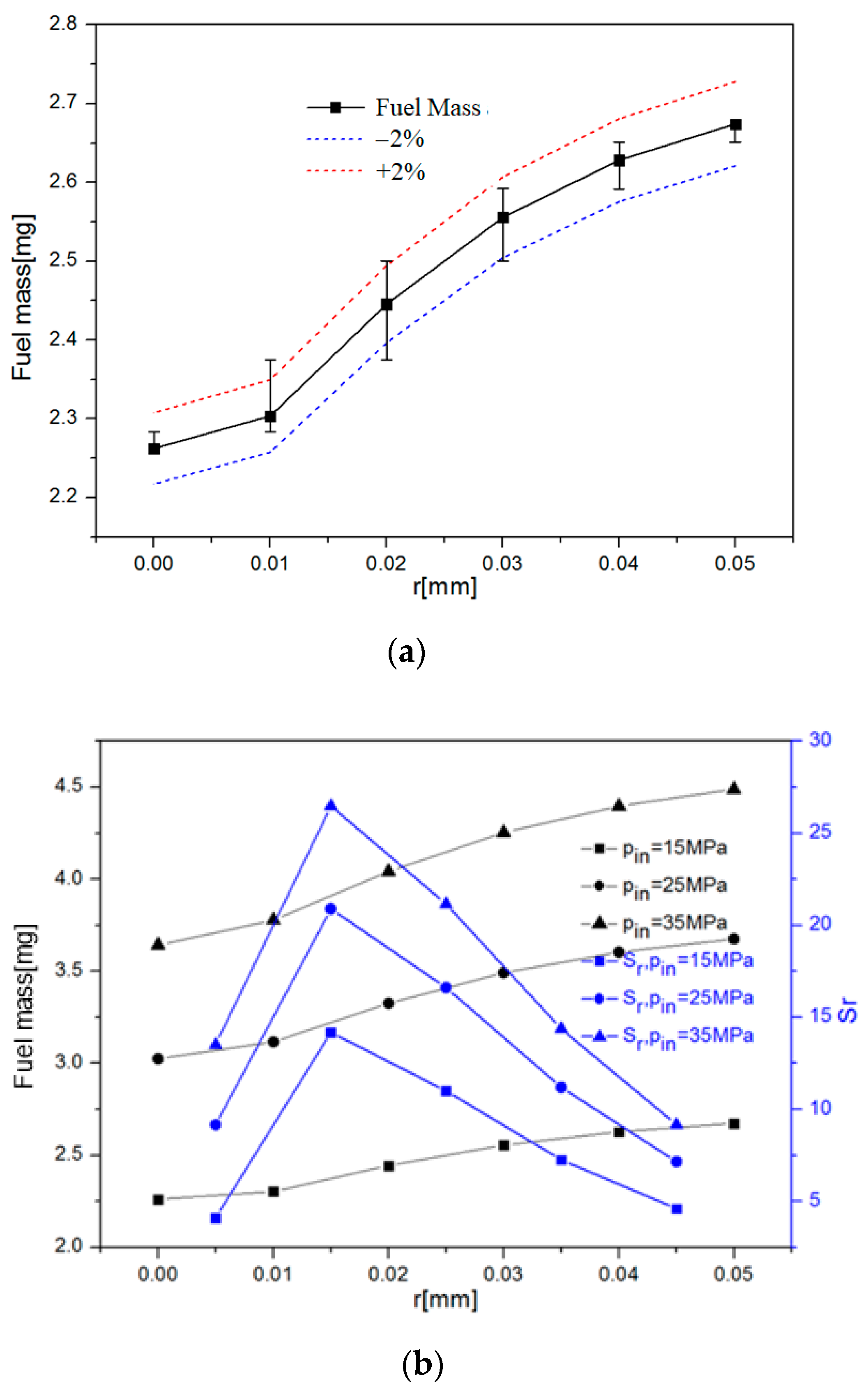
3.3. Sensitivity Analysis of Fuel Mass to Inlet Orifice Radius

Figure 7 displays the effect of the inlet orifice radius on the fuel mass and the sensitivity coefficient of cycle injection fuel mass to the inlet orifice radius. A 2% fluctuation range for cycle injection fuel mass is defined as a reasonable range. Figure 7a shows the variation in fuel mass caused by the machining accuracy of ±5 μm of the inlet orifice radius. The injection pressure is 15 MPa, and the back pressure is 0.5 MPa. It could be seen that near r = 0.02 mm, the variation in fuel mass caused by the nozzle chamfer fluctuation is beyond the allowable range. However, at r < 0.01 mm or r > 0.03 mm, the variation in cycle injection fuel mass could meet the requirement. With the increase in inlet orifice radius, the variation in cycle injection fuel mass caused by the machining accuracy decreases gradually. Figure 7b shows the effect of inlet orifice radius on the cycle injection fuel mass under different injection pressures. In the scope of this study, the variation trend of cycle injection fuel mass with respect to the increase in entrance chamfer radius is the same under different injection pressures. With the increase in inlet orifice radius, the cycle injection fuel mass increases, and the tendencies are stabilized gradually. This is mainly because the entrance chamfer causes the local resistance to decrease and the flow coefficient to increase. With the increase in inlet orifice radius, the change in the flow section of the inlet becomes more moderate, the transition area becomes larger and the local resistance at the nozzle entrance decreases gradually. Therefore, with the increase in the chamfer radius, the cycle injection fuel mass has a tendency to stabilize gradually. It can be deemed that the sensitivity coefficient increases with the increase in chamfer radius from r = 0.00 to 0.02 mm. Near r = 0.02 mm, cycle fuel mass is most sensitive to the inlet orifice radius. And then, with the further increase in the entrance chamfer radius r, the sensitivity decreases gradually. It can be seen that the chamfer radius near r = 0.02 mm should be avoided when optimizing the design of the nozzle, otherwise higher machining accuracy is needed to process the nozzle inlet chamfer. According to the sensitivity coefficient of fuel mass to the inlet chamfer under different injection pressures, the sensitivity coefficient curve increases with the increase in injection pressure, indicating that the sensitivity of internal flow to the entrance chamfer r is enhanced. Therefore, we should pay more attention to the machining accuracy of the nozzle inlet chamfer in order to ensure the consistency of the structure size between the nozzles.
It is necessary to have a comprehensive understanding about the effect of the inlet orifice radius on the inner-nozzle flow characteristic. Figure 8 displays the gas–liquid phase distribution of the injector nozzle under different entrance chamfers. The red color means the liquid fraction volume (LVF) = 1, whereas the blue color means the LVF = 0. It could be seen that when r = 0.00 mm, the fuel at the orifice exit obviously peels off the upper wall of the orifice, and the gas phase ratio of each section is larger. The gas phase ratio in the small nozzle decreases obviously when r = 0.04 mm is applied, and the gas phase ratio in the A-A section is almost zero, and the liquid phase ratio of C-C in the exit section is obviously smaller than that in r = 0.00 mm. Therefore, it can be concluded that the change in the nozzle entrance chamfer has an effect on the inception and development of the cavitation in the nozzle. With the increase in the nozzle entrance chamfer, the generation and development of cavitation are inhibited. The volume of cavitation in the nozzle decreases, thus the effective flow cross-section area increases and the local resistance decreases.

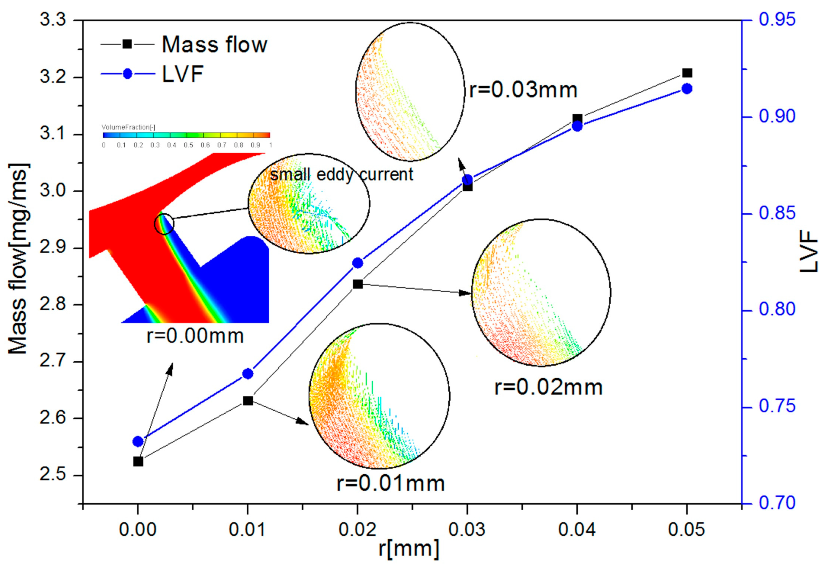
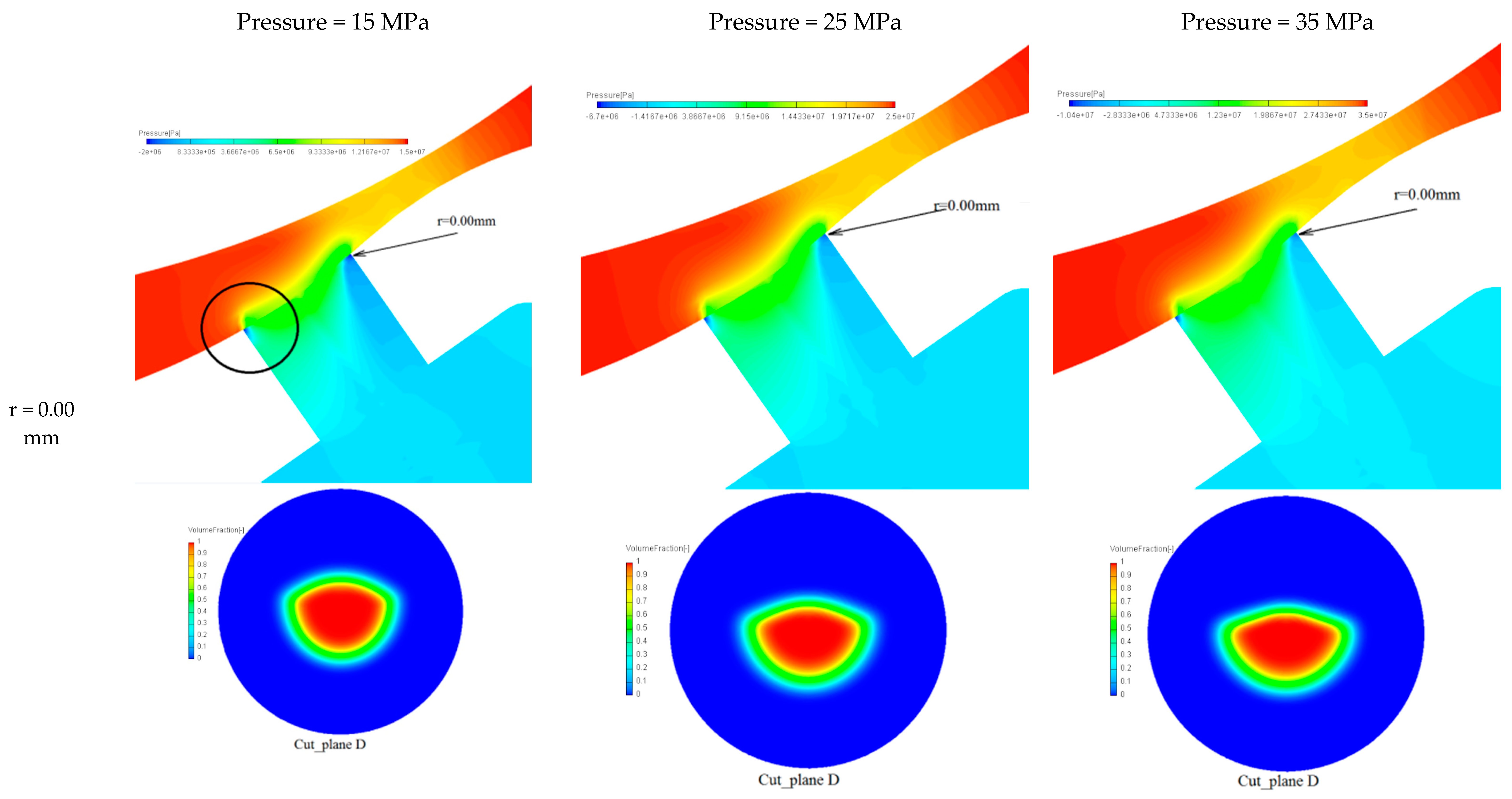
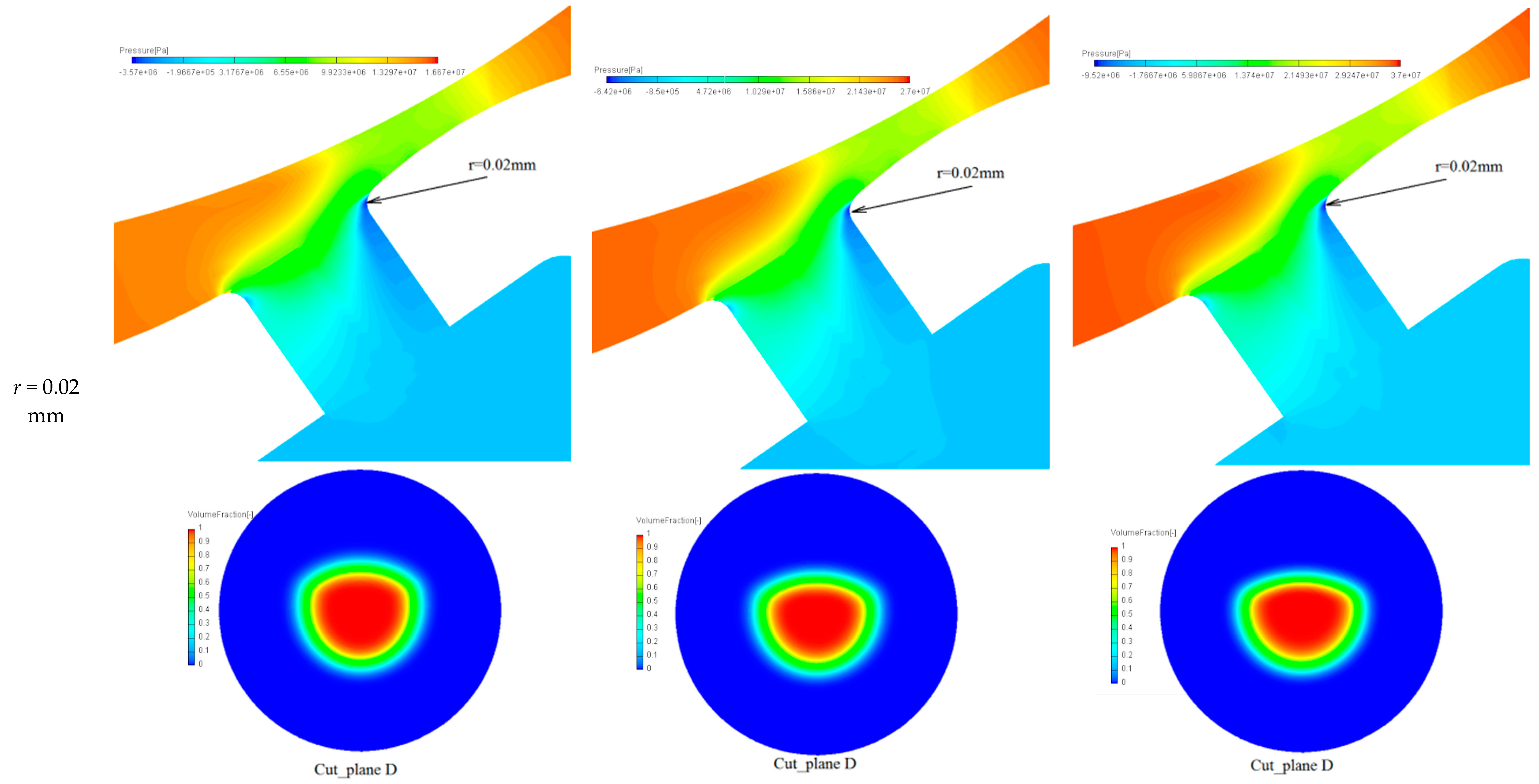
3.4. Effect of Inlet Orifice Radius on the Near-Nozzle Flow Characteristic

The fuel jet condition of the nozzle outlet would directly affect the spray characteristic in the cylinder. To analyze the effect of inlet orifice radius on the near-nozzle flow characteristic, Figure 9 shows the liquid fraction volume of the nozzle outlet. With the increase in the inlet orifice radius, the LVF of the small nozzle outlet increases, and the increase slows down gradually. When the nozzle entrance chamfer is small, the liquid phase peeling wall is serious, and the cavitation phenomenon is obvious due to the local eddy current and other reasons. With the increase in injection pressure, the liquid volume fraction at the nozzle outlet decreases. Due to the increase in the pressure difference between the inlet and outlet, there is an increase in fuel flow velocity and the local negative pressure area in the injector nozzle; thus, the cavitation phenomenon intensifies. The change in injection pressure from 25 MPa to 35 MPa on the liquid phase volume fraction is smaller than that of the injection pressure from 15 MPa to 25 MPa. And with the increase in the nozzle inlet chamfer radius, the difference decreases gradually. Therefore, the increase in the nozzle inlet chamfer can effectively reduce the effect of injection pressure on the accuracy and consistency of the injector.
The change in cavitation in the injector nozzle is mainly due to the effect of the internal and external pressure difference, which results in the increase in the flow velocity and the reduction in the local pressure below the saturated vapor pressure when the liquid oil flows through the injection hole. Figure 10 shows the pressure distribution in the nozzle and the liquid phase distribution at the nozzle outlet under different injection pressures. It can be seen from the figure that when r = 0.00 mm, the area of negative pressure appears obviously in the upper wall of the nozzle; the fuel produces cavitation and extends outward in this area. And there is also a small area of negative pressure in the lower wall of the nozzle entrance, but because the area is small and the surrounding oil pressure is high, the phenomenon of cavitation is not obvious. With the increase in fuel injection pressure, the negative pressure area near the upper wall expands and the negative pressure limit increases. With the increase in the inlet orifice radius, the negative pressure area of the nozzle decreases, and the negative pressure area near the lower wall will disappear. Therefore, the entrance chamfer effectively reduces the abrupt change in flow cross-section from the oil chamber to the nozzle, the negative pressure area and the local resistance, thus inhibiting the generation and development of cavitation. In the figure, Cut_plane D is the liquid fraction volume distribution at the outlet of the large nozzle, and the increase in injection pressure is apt to aggravate the eccentricity of the jet shape and the exchange of gas and liquid phases. With the increase in the inlet chamfer, the effect of the injection pressure on the liquid fraction volume of the outlet is weakened. When r = 0.05 mm, the liquid phase distribution of fuel is not affected by the injection pressure. Therefore, the optimization of the inlet orifice radius can effectively improve the consistency of fuel injection characteristics between nozzles and productions of the GDI injector.

4. Conclusions

Based on the method of single factor contrast analysis, the injection law, cycle fuel mass and liquid phase distribution field in different nozzle inlet chamfers were simulated and analyzed. The conclusions are listed as follows:
With the increase in the entrance chamfer, the generation and development of cavitation in the GDI injector nozzle are restrained, the local resistance of the nozzle is reduced, and the flow coefficient is increased.
At r = 0.02 mm, the cycle injection fuel mass is most sensitive to the inlet orifice radius of the GDI injector nozzle. The increase in injection pressure will increase the sensitivity coefficient of fuel mass to the entrance chamfer and the processing accuracy of the nozzle inlet orifice radius.
The increase in injection pressure intensifies the jet deviation from the nozzle axis, whereas the increase in the nozzle entrance chamfer can effectively reduce the deviation. Therefore, the injection characteristics of the injector can be improved by optimizing the design of the entrance chamfer of the injector nozzle.

Author Contributions

Conceptualization, X.L.; methodology, J.G.; software, B.S. and P.Z.; validation, X.L.; formal analysis, B.S. All authors have read and agreed to the published version of the manuscript.

Funding

This research was funded by the [Shandong Provincial Natural Science Foundation] grant number [ZR2021QE065].

Data Availability Statement

Data are contained within the article.

Conflicts of Interest

The authors declare no conflicts of interest.

Nomenclature

GDIgasoline direct injection
υ 1 inlet velocity of the CFD model
υ 2 outlet velocity of the injector nozzle
pininjection pressure
pbackback pressure
pvsaturated vapor pressure
m ˙ injector nozzle mass flow
Cdthe discharge coefficient
Srsensitivity coefficient
Δdthe change in inlet orifice radius
CNcavitation number
ξlocal resistant coefficient
hllocal resistance

References

  1. Fontanesi, S.; D’adamo, A.; Rutland, C.J. Large-Eddy simulation analysis of spark configuration effect on cycle-to-cycle variability of combustion and knock. Int. J. Engine Res. 2015, 16, 403–418. [Google Scholar] [CrossRef]
  2. Breda, S.; D’Adamo, A.; Fontanesi, S.; Giovannoni, N.; Testa, F.; Irimescu, A.; Merola, S.; Tornatore, C.; Valentino, G. CFD analysis of combustion and knock in an optically accessible GDI engine. SAE Int. J. Engines 2016, 9, 641–656. [Google Scholar] [CrossRef]
  3. Qiu, T.; Song, X.; Lei, Y.; Liu, X.; An, X.; Lai, M. Influence of inlet pressure on cavitation flow in diesel nozzle. Appl. Therm. Eng. 2016, 109, 364–372. [Google Scholar] [CrossRef]
  4. Wu, S.; Xu, M.; Hung, D.L.; Pan, H. In-nozzle Flow Investigation of Flash Boiling Fuel Sprays. Appl. Therm. Eng. 2016, 117, 644–651. [Google Scholar] [CrossRef]
  5. Wu, S.; Xu, M.; Hung, D.L.; Li, T.; Pan, H. Near-nozzle spray and spray collapse characteristics of spark-ignition direct-injection fuel injectors under sub-cooled and superheated conditions. Fuel 2016, 183, 322–334. [Google Scholar] [CrossRef]
  6. Duke, D.J.; Kastengren, A.L.; Matusik, K.E.; Swantek, A.B.; Powell, C.F.; Payri, R.; Vaquerizo, D.; Itani, L.; Bruneaux, G.; Grover, R.O., Jr.; et al. Internal and Near Nozzle Measurements of Engine Combustion Network “Spray G” Gasoline Direct Injectors. Exp. Therm. Fluid Sci. 2017, 88, 608–621. [Google Scholar] [CrossRef]
  7. Saha, K.; Som, S.; Battistoni, M.; Li, Y.; Quan, S.; Senecal, P.K. Numerical simulation of internal and near-nozzle flow of a gasoline direct injection fuel injector. J. Phys. Conf. Ser. 2015, 656, 012100. [Google Scholar] [CrossRef]
  8. Giussani, F.; Montorfano, A.; Piscaglia, F.; Onorati, A.; Hélie, J.; Aithal, S. Dynamic VOF Modelling of the Internal Flow in GDI Fuel Injectors. Energy Procedia 2016, 101, 574–581. [Google Scholar] [CrossRef]
  9. Zhang, M.J.; Songr, Z.; Ju, Y.S.; Wang, L.L. The effect of cavitation on the inner-flow and spray characteristic of GDI injector. Veh. Engine 2015, 6, 79–84. [Google Scholar] [CrossRef]
  10. Cheng, Q.; Zhang, Z.D.; Xie, N.L.; Zhu, X. Influence of Nozzle Configuration on Spray Characteristics of Multi-Hole GDI Injector. Trans. CSICE 2014, 32, 45–51. [Google Scholar]
  11. Payri, R.; Salvador, F.J.; Martí-Aldaraví, P.; Vaquerizo, D. ECN Spray G External Spray Visualization and Spray Collapse Description through Penetration and Morphology Analysis. Appl. Therm. Eng. 2017, 112, 304–316. [Google Scholar] [CrossRef]
  12. Chan, Q.N.; Bao, Y.; Kook, S. Effects of injection pressure on the structural transformation of flash-boiling sprays of gasoline and ethanol in a spark-ignition direct-injection (SIDI) engine. Fuel 2014, 130, 228–240. [Google Scholar] [CrossRef]
  13. Lee, S.; Park, S. Spray atomization characteristics of a GDI injector equipped with a group-hole nozzle. Fuel 2014, 137, 50–59. [Google Scholar] [CrossRef]
  14. Li, X.; Cheng, Y.; Ma, X.; Yang, X. A correction method of hole-to-hole variation mass flow of diesel injector equipped on a common-rail DI diesel engine. Eur. Phys. J. Appl. Phys. 2018, 83, 30902. [Google Scholar] [CrossRef]
  15. Li, X.; Cheng, Y.; Ji, S.; Yang, X.; Wang, L. Sensitivity analysis of fuel injection characteristics of GDI injector to injector nozzle diameter. Energies 2019, 12, 434. [Google Scholar] [CrossRef]
  16. Salvador, F.; Romero, J.-V.; Roselló, M.-D.; Martínez-López, J. Validation of a code for modeling cavitation phenomenain Diesel injector nozzles. Math. Comput. Model. 2010, 52, 1123–1132. [Google Scholar] [CrossRef]
  17. Saha, K.; Som, S.; Battistoni, M.; Li, Y.; Quan, S.; Senecal, P.K. Modeling of Internal and Near-nozzle flow for a Gasoline Direct Injection Fuel Injector. J. Energy Resour. Technol. 2016, 138, 052208. [Google Scholar] [CrossRef]
  18. Li, X.; Cheng, Y.; Ma, X.; Yang, X. The sensitivity of inner nozzle flow in GDI injector to thenozzle geometry parameters. J. Eng. GasTurbines Power 2019, 141, 061017. [Google Scholar] [CrossRef]
  19. Du, G.S.; Tian, R. Fluid Mechanics; China Electric Power Press: Beijing, China, 2007; pp. 120–124. [Google Scholar]
Figure 1. The model of simulation: (a) GDI injector nozzle; (b) structure parameters of nozzle.
Processes 12 01740 g001
Figure 2. The range of inlet orifice radius.
Processes 12 01740 g002
Figure 3. Assumptions of simulation initial condition: (a) initial pressure distribution; (b) initial fuel distribution.
Processes 12 01740 g003
Figure 4. Injection mass flow of the Spray G injector nozzle.
Processes 12 01740 g004
Figure 5. The effect of the inlet orifice radius on the injection mass flow.
Processes 12 01740 g005
Figure 6. The effect of different inlet orifice radii on the discharge coefficient.
Processes 12 01740 g006
Figure 7. The sensitivity analysis of nozzle cycle fuel mass to the inlet orifice radius: (a) variation in cycle fuel mass; (b) sensitivity coefficient.
Processes 12 01740 g007
Figure 8. The cut-plane of LVF under different inlet orifice radii.
Processes 12 01740 g008
Figure 9. The LVF of injector outlet under different injection pressures.
Processes 12 01740 g009
Figure 10. The effect of different injection pressures and inlet orifice radii on the nozzle inner-flow.
Processes 12 01740 g010aProcesses 12 01740 g010bProcesses 12 01740 g010c
Table 1. Parameters of injector and boundary condition.
TypeValueTypeValue
InjectorGDI injectorFuelGasoline
Nozzle number6Density0.7–0.78 kg/m3
d0.15 mmDynamic viscosity0.76 mm2/s
L10.15 mmBND_inlet15, 25 and 35 MPa
D0.45 mmBND_Outlet0.5 MPa
L20.45 mmTemperature293.7 K
R0.04 mmNeedle_movingMove
α35°SymmetryPeriodic
Disclaimer/Publisher’s Note: The statements, opinions and data contained in all publications are solely those of the individual author(s) and contributor(s) and not of MDPI and/or the editor(s). MDPI and/or the editor(s) disclaim responsibility for any injury to people or property resulting from any ideas, methods, instructions or products referred to in the content.

