Pressurized Regenerative Calcium Cycle for Utility-Scale Energy Storage: A Techno-Economic Assessment
Abstract
:1. Introduction
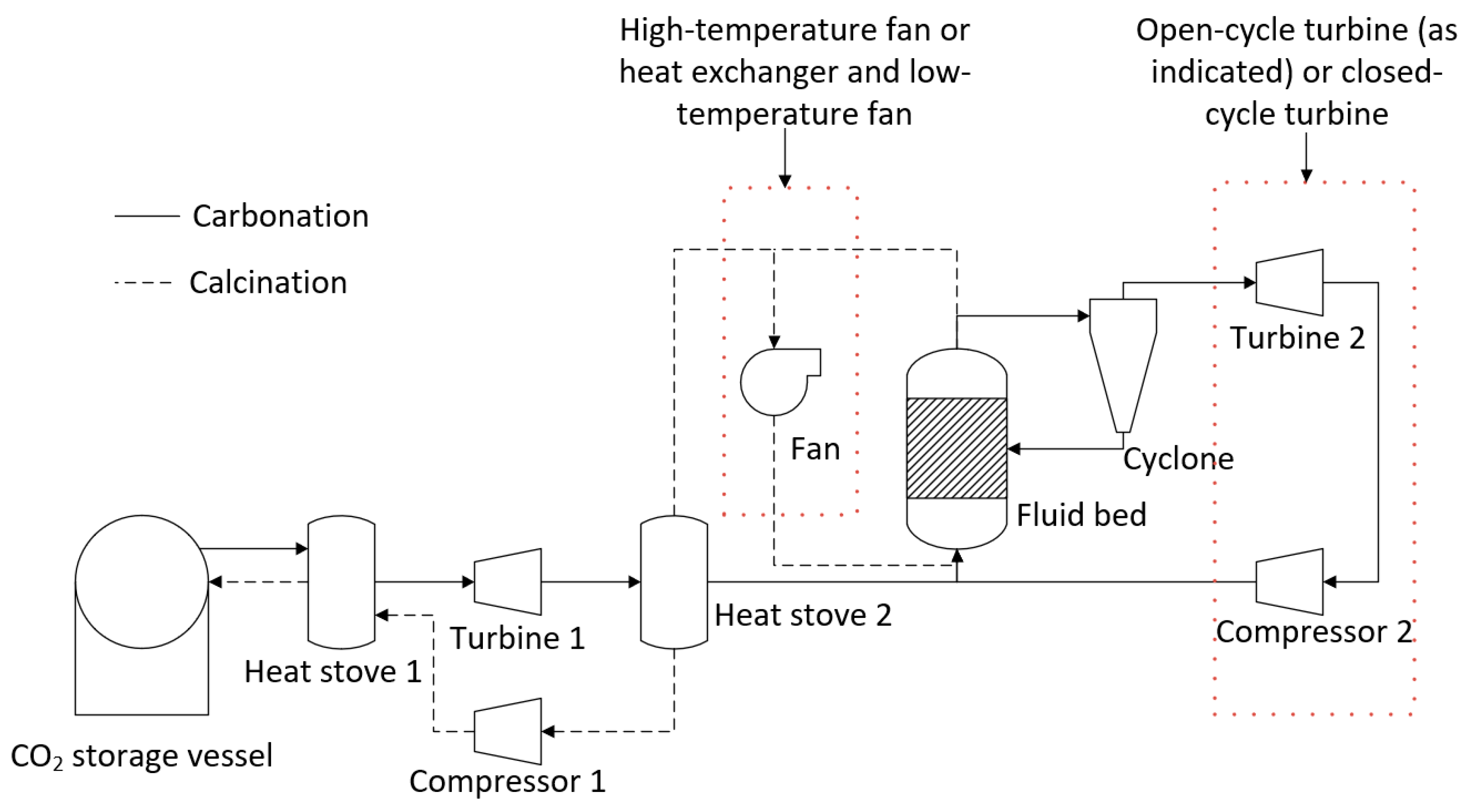
- Open-cycle or closed-cycle configuration for turbines—An open-cycle configuration would likely provide the greatest output from the turbine. However, there is the possibility that fine particles from the fluid bed may not be removed by the cyclone. These particles would have a detrimental impact on the turbine. High-temperature filtration of the off-gas is a possible solution, or a closed-cycle system could be employed. A closed-cycle process in which there is no direct contact between the fluid bed off-gas and the turbine working fluid would avoid the issue of entrained particles damaging the turbine. However, the output from the turbine would decrease. One advantage of a closed-cycle system is that the carbonation cycle could be undertaken at atmospheric conditions, reducing the construction cost of the fluid bed.
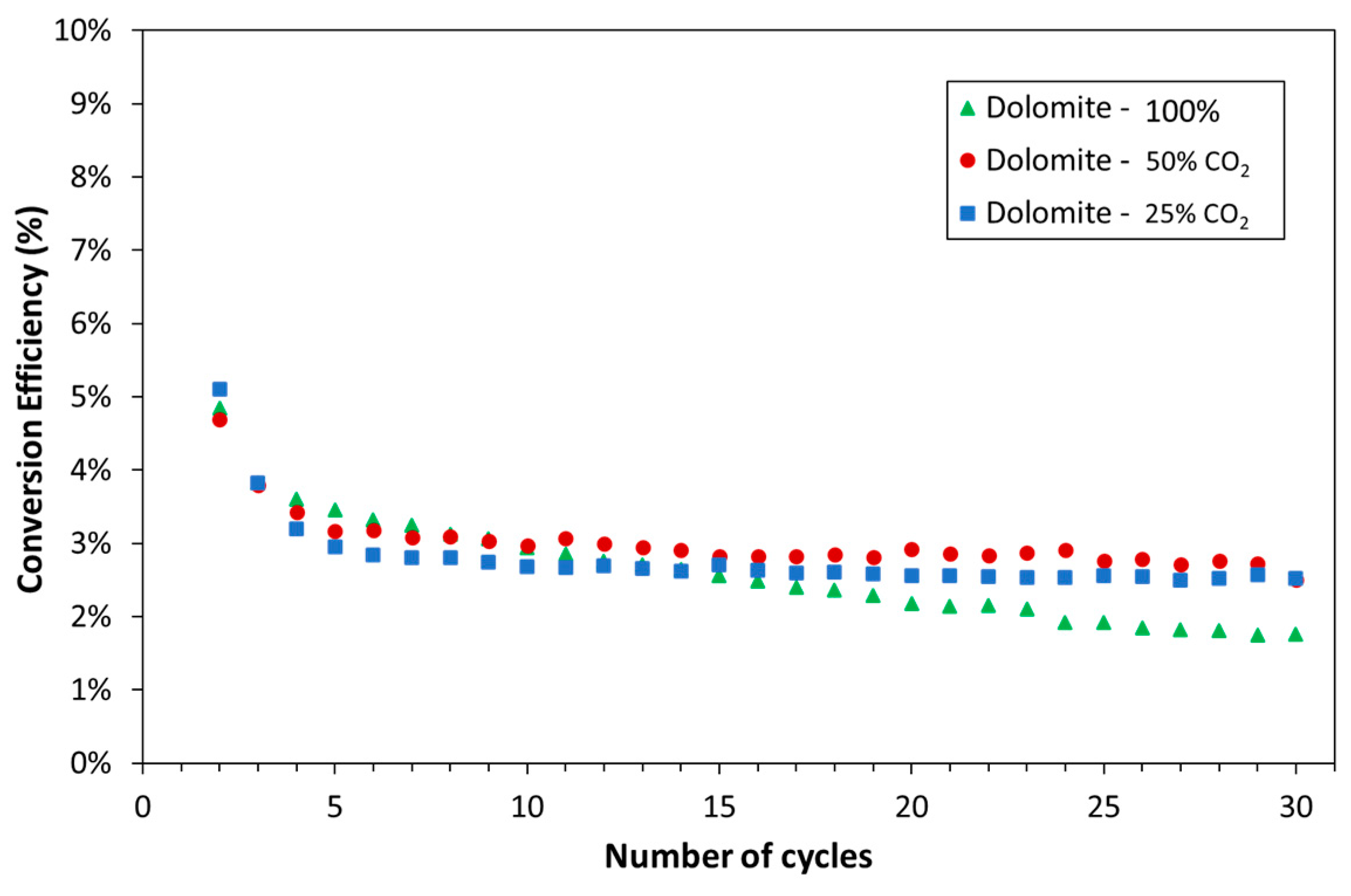
- Atmospheric or pressurized carbonation reactor—For an open-cycle turbine, the fluid bed would be operated at the inlet pressure required by the turbine. The capital cost for a pressurized fluid bed is significantly greater than for an atmospheric fluid bed. If a closed-cycle turbine is employed, then there is no requirement for the fluid bed to operate above atmospheric pressure. The conversion of calcium oxide in multicycle systems (i.e., the amount of material that will convert to limestone in each cycle) is known to decrease and converge toward a constant value. The final value is a function of the process conditions, including the pressure of the system. The conversion would determine the quantity of material required for a given power output, and therefore influences the size of the fluid bed. Optimization of the process conditions in order to reduce the capital costs would follow.
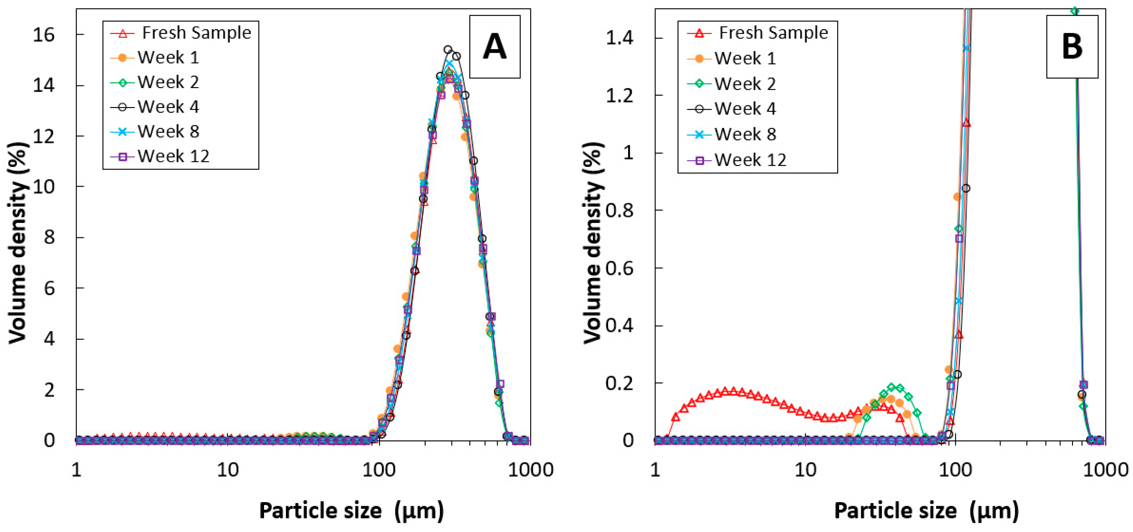
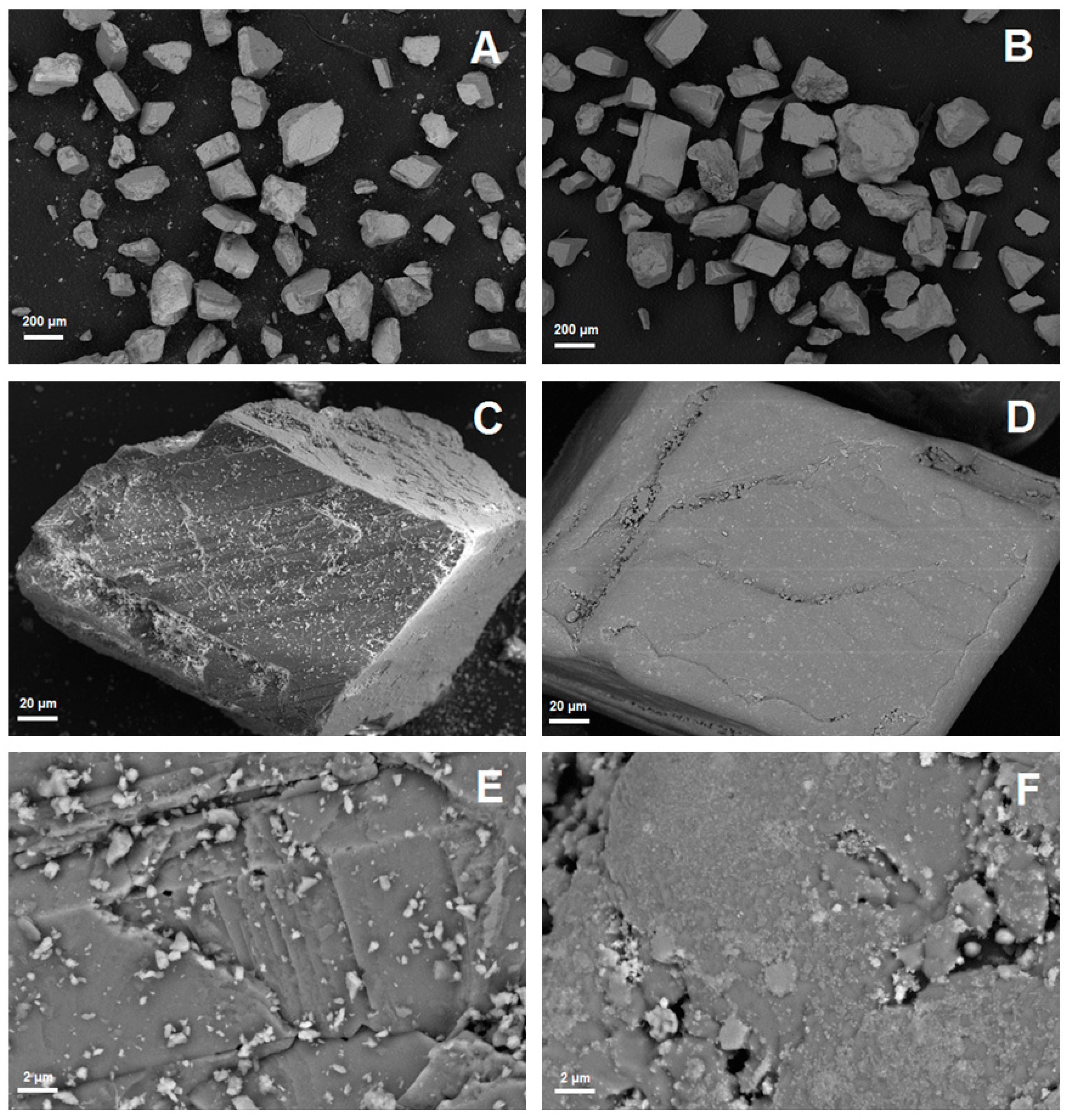
- Carbonate material reactivity and physical properties—The reactivity and conversion of the carbonate material (calcium carbonate or alternatives) will influence the quantity of material required and the size and geometry of the fluid bed. The other key consideration for the bed material is the change in the particle size distribution through multiple calcination and carbonation cycles. Changes in particle size distribution will impact the reaction kinetics and the cyclone performance. Alternative carbonate materials with a greater mechanical strength may be suitable for the PRC2 process. These materials typically contain a lower percentage of carbonate compared with calcium carbonate, and therefore a greater mass of material would be required for the same power output.
- Heat storage methods—Heat stoves, essentially thermal storage vessels, were proposed as a means to transfer heat from the calcination cycle to the carbonation cycle. Heat stoves operate by direct contact between the gas stream and the solid thermal storage material. Consequently, the heat-stove vessel must be rated to the same pressure as the gas stream. In the preliminary concept design, Heat Stove 1 would be at 80 bar (the same pressure as the bulk carbon dioxide storage vessel) and Heat Stove 2 would be at 4 bar (the same pressure required for the inlet to the fluid bed and Turbine 2 for an open-cycle system). Constructing large pressure vessels for heat stoves may be cost-prohibitive. Alternatives include indirect heat storage methods, in which the gas pipes are pressure-rated and the heat-stove vessels are at atmospheric pressure.
- CO2 recycling stream for fluidization during calcination—A fraction of the carbon dioxide in the off-gas during calcination will need to be recycled to maintain fluidization of the bed material. The off-gas during calcination will be between 900–950 °C. High-temperature fans may be cost-prohibitive for the recycling process. Alternatively, the entire off-gas stream could be passed through Heat Stove 2 and a fraction of the cold gas stream could be passed back through a fan and heat exchanger before it re-entered the bed.
2. Materials and Methods
2.1. Overview
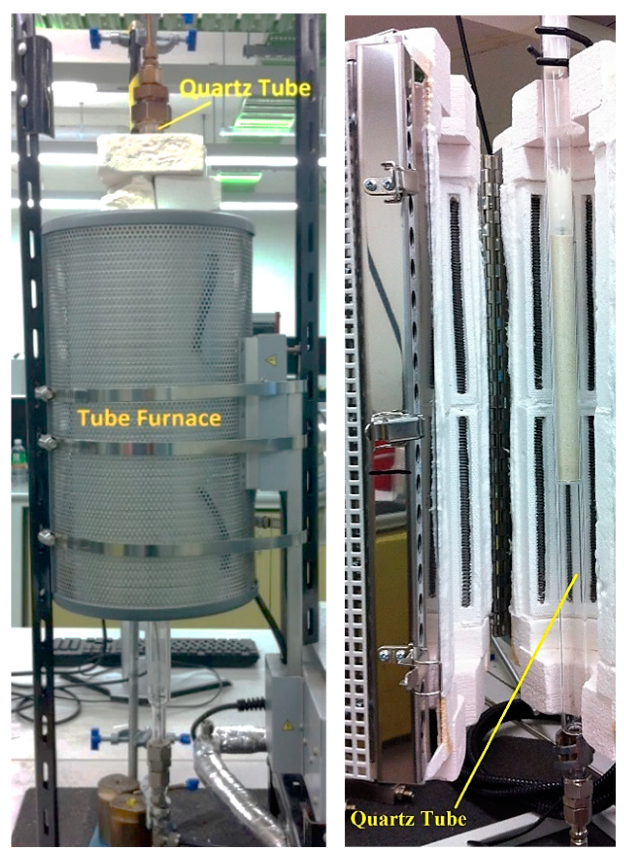
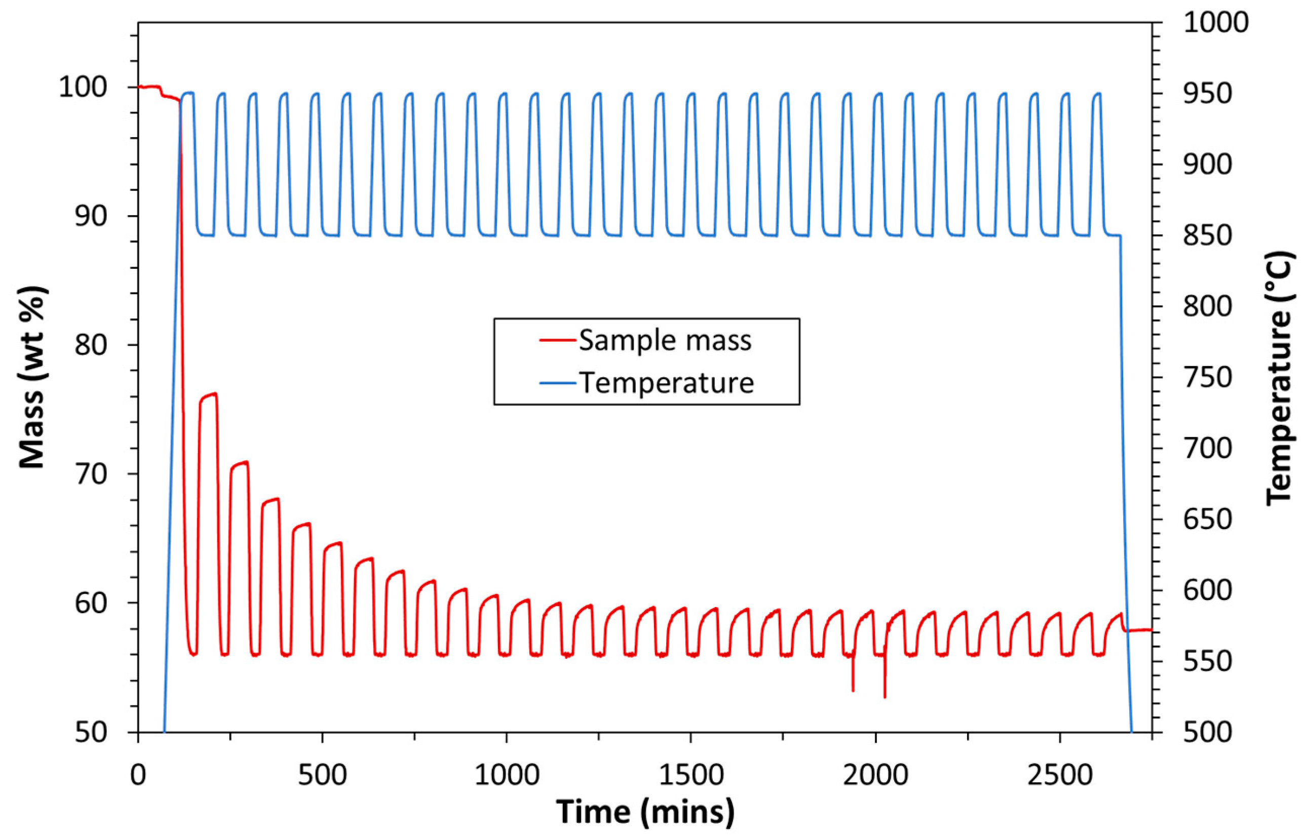
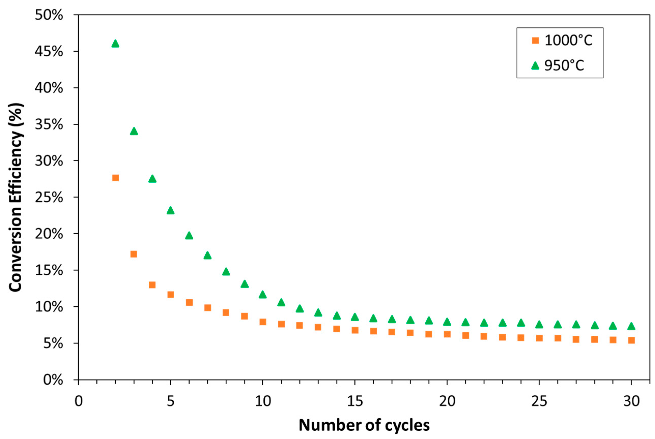
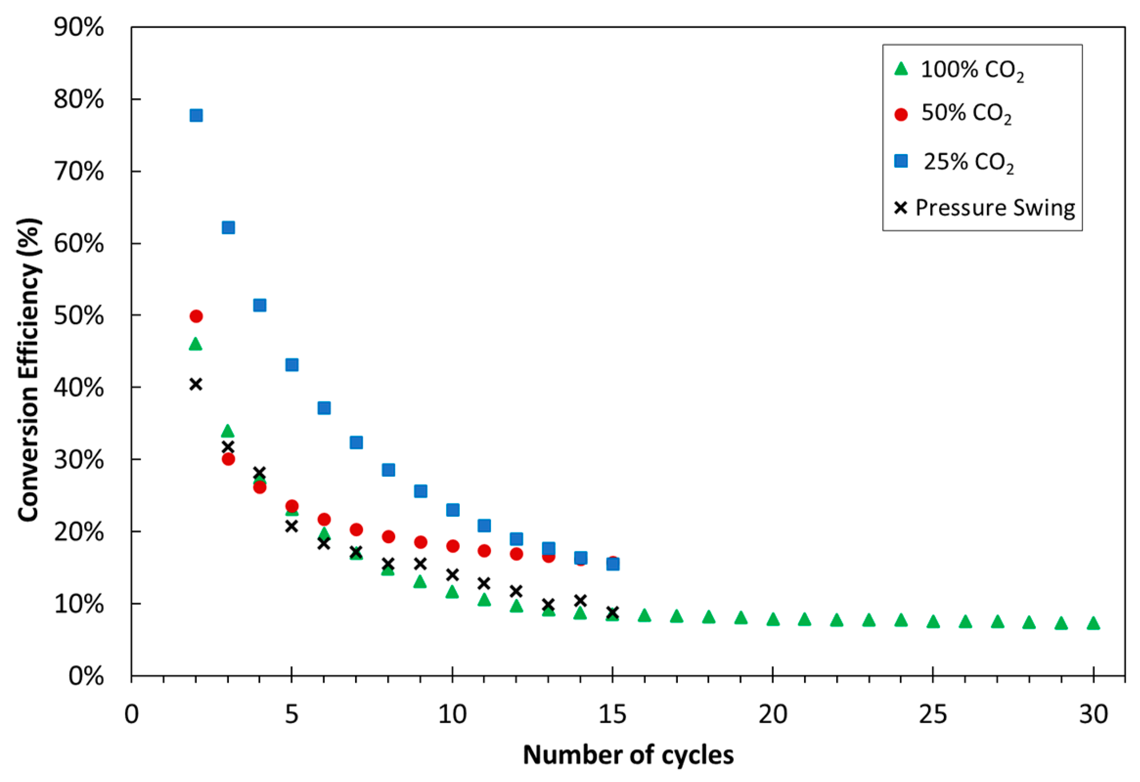
- Experimental—The experimental work involved high pressure thermogravimetric analyzer (HP-TGA) experiments and laboratory-scale particle analysis.
- Process modelling—For each concept design, process modelling was carried out using the open-source chemical looping simulator DWSIM.
- Techno-economic assessment—For each concept, the LCOS was determined by using the standard approach reported in the open literature.
2.2. Experimental
2.3. Alternative Configurations for the PRC2 Process
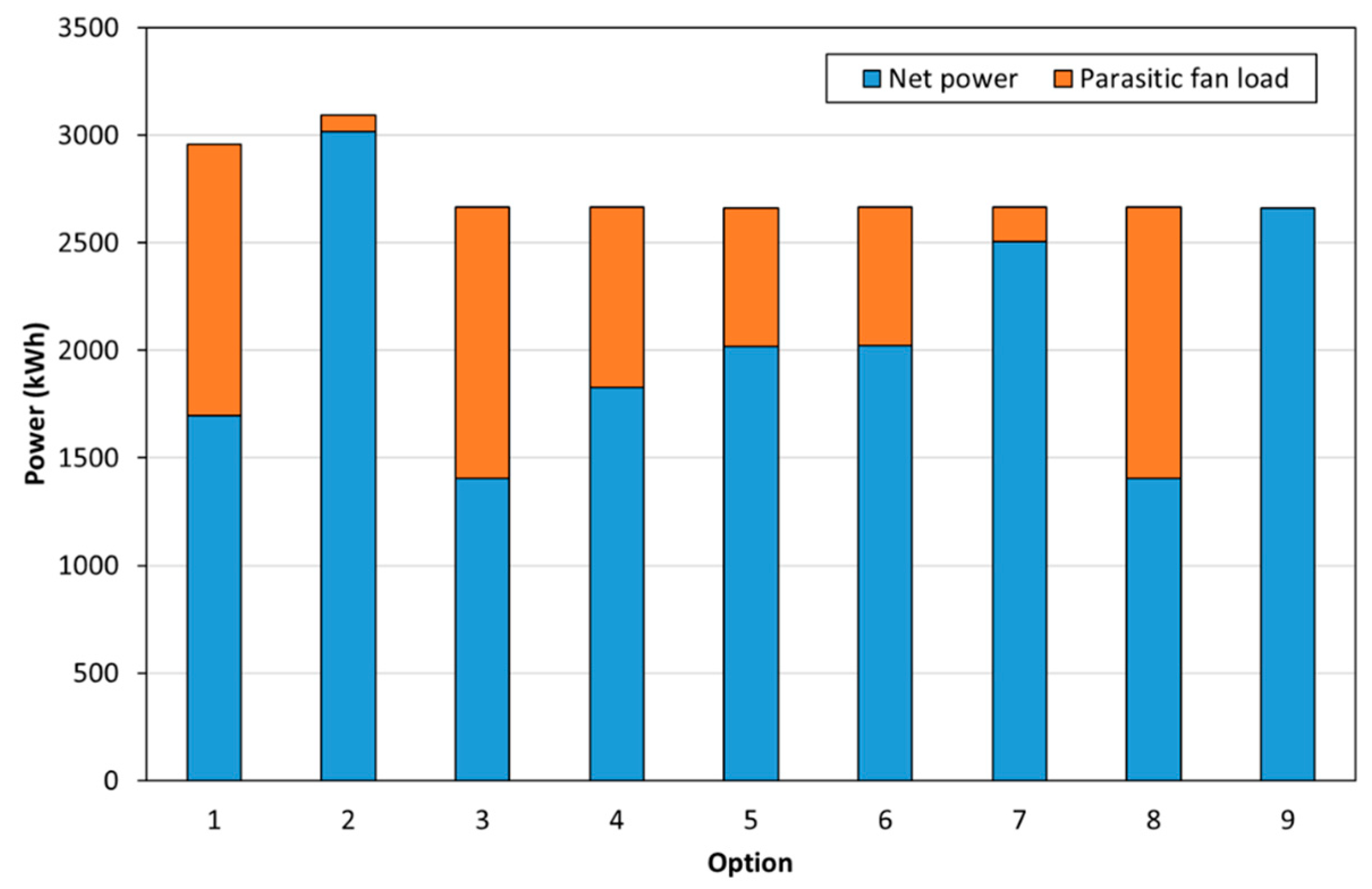
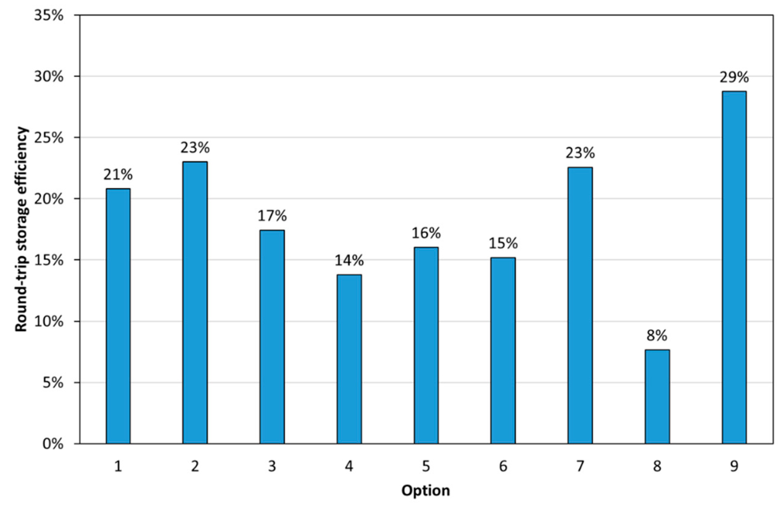
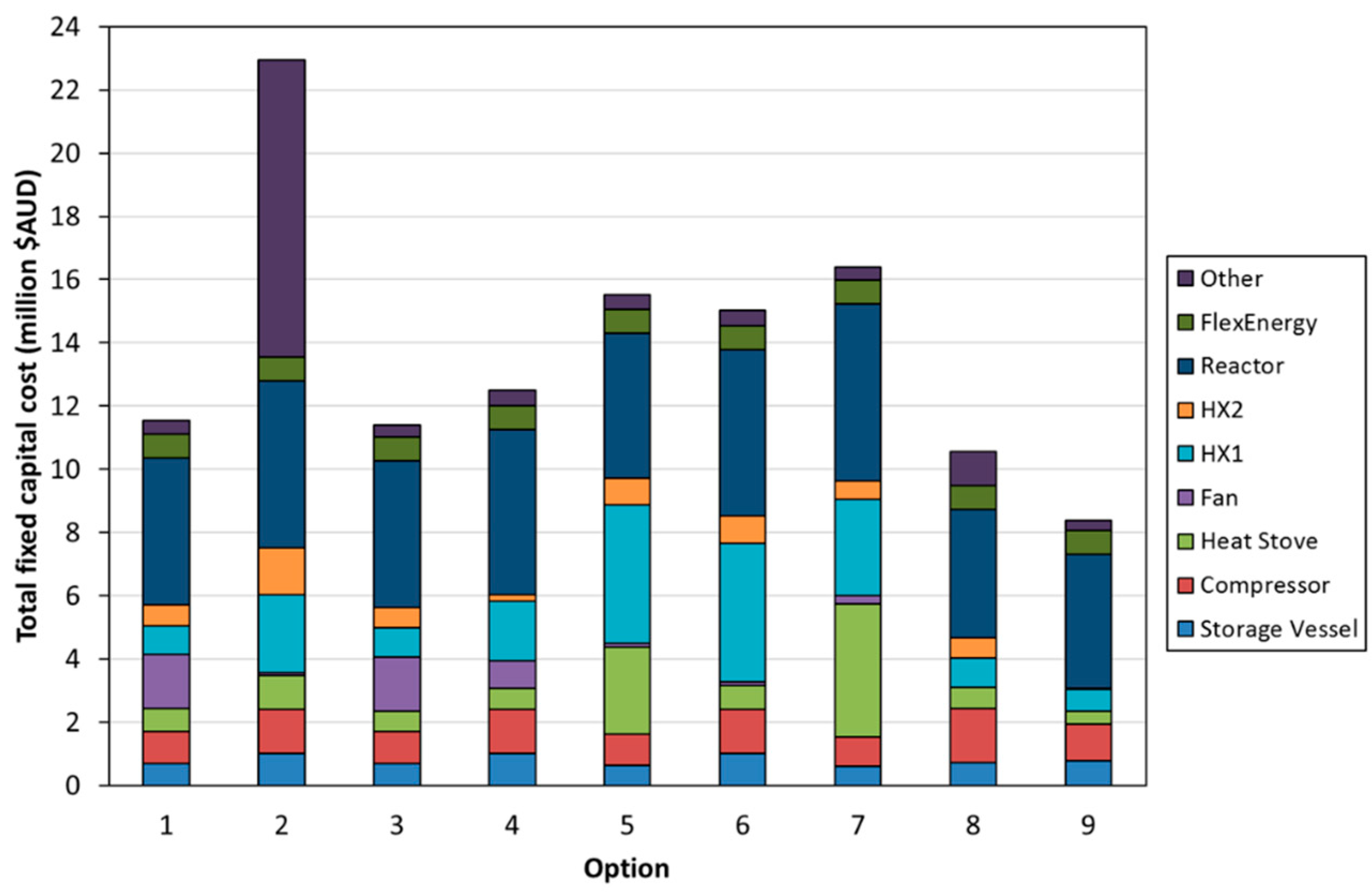
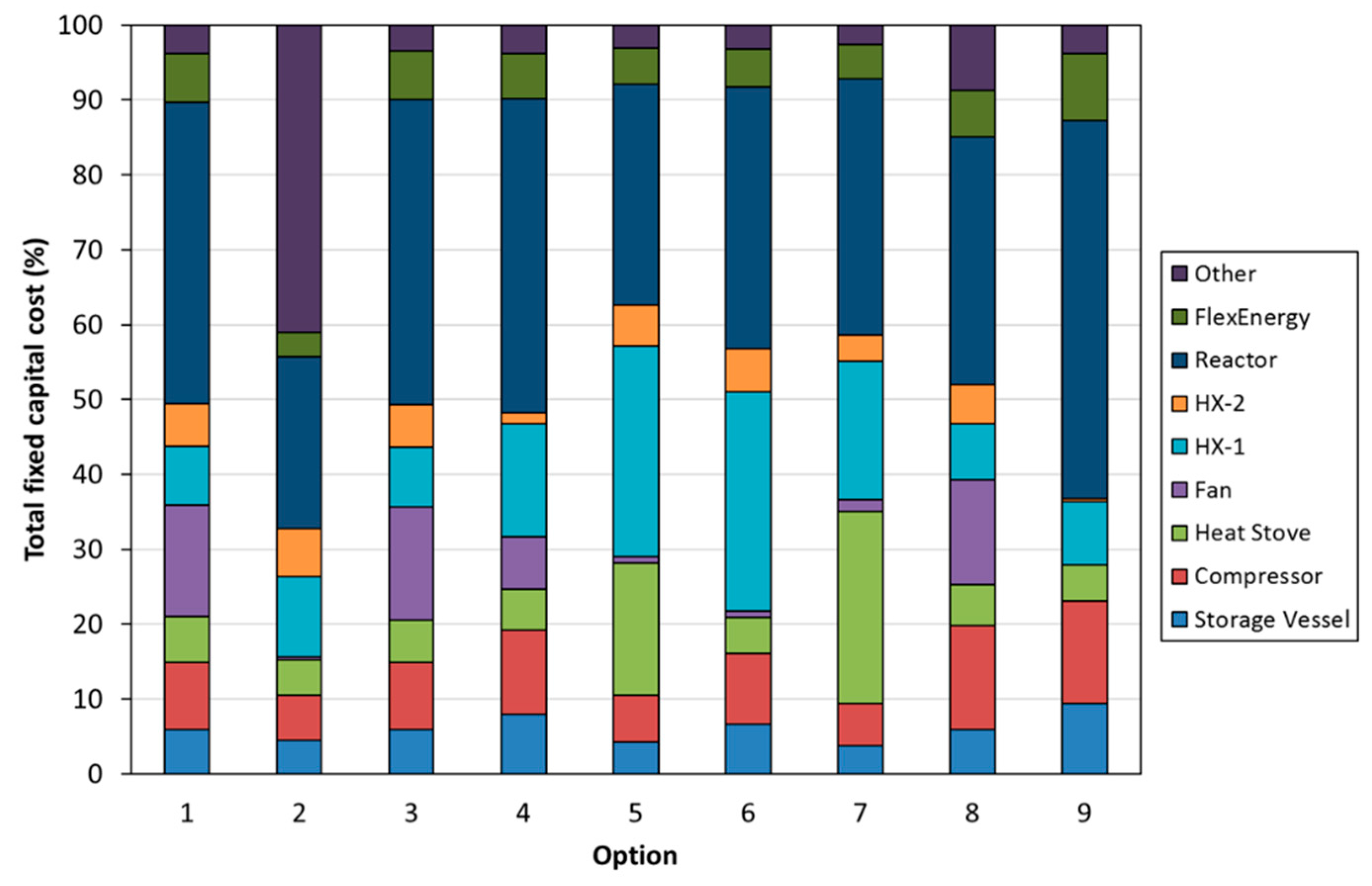
- Option 1—Temperature swing process with indirect power generation. The hot fluid bed off-gas (CO2) was passed through a heat exchanger to heat the turbine working fluid (air). A high-temperature fan was used to circulate CO2 in the system. A single heat stove was used to cool and heat CO2 entering and leaving the CO2 storage vessel. A second turbine was used to recover energy as CO2 was expanded from the storage vessel.
- Option 2—Temperature swing process with direct power generation. The hot fluid bed off-gas (CO2) was used directly in the turbine. Before passing through the turbine, the gas was filtered to remove any particles from the circulating stream. The filtration step required additional heat exchangers to satisfy the operating temperatures of the filter and compressor. Option 2 had a configuration entering and exiting the CO2 storage vessel similar to that of Option 1.
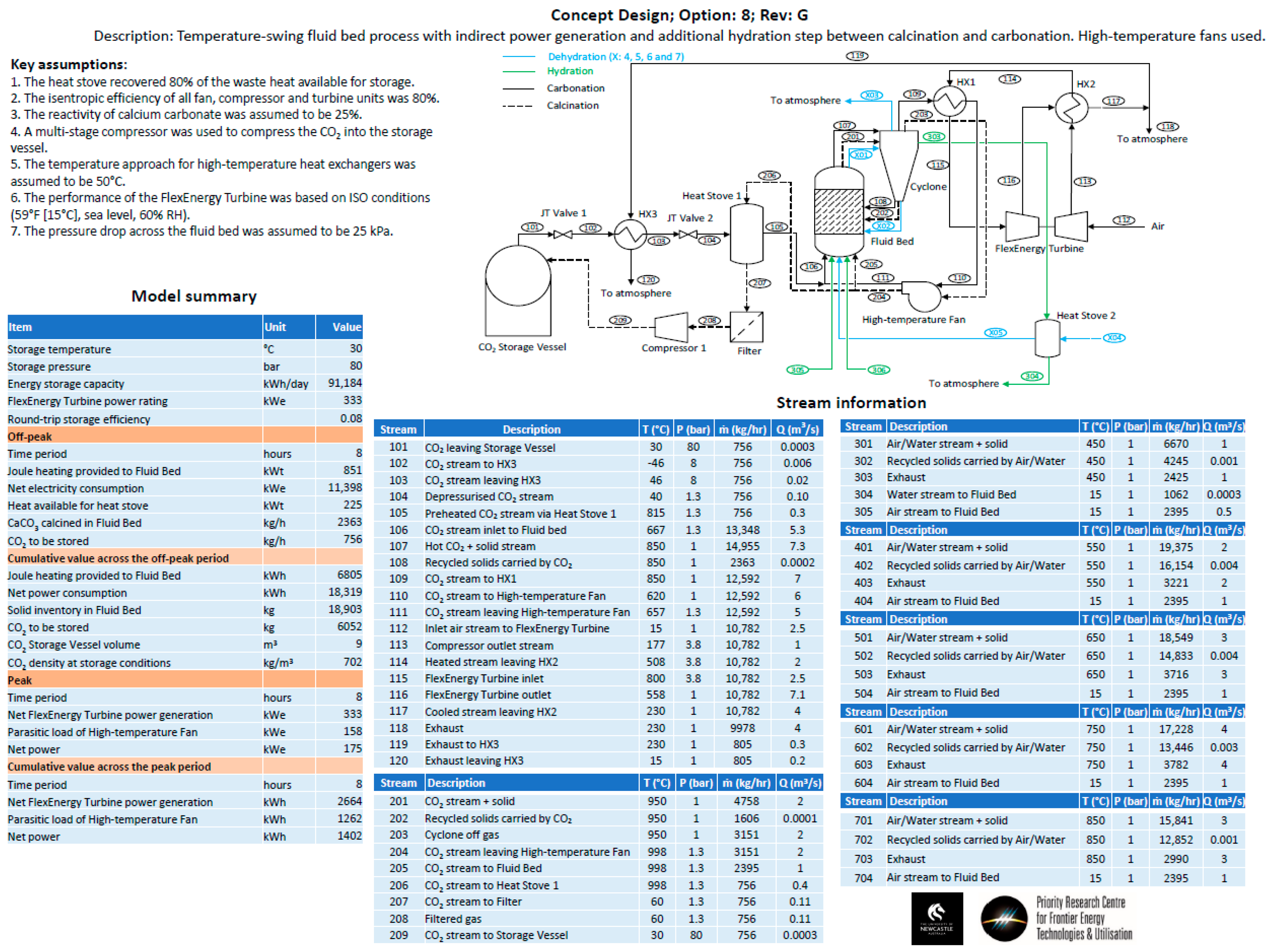
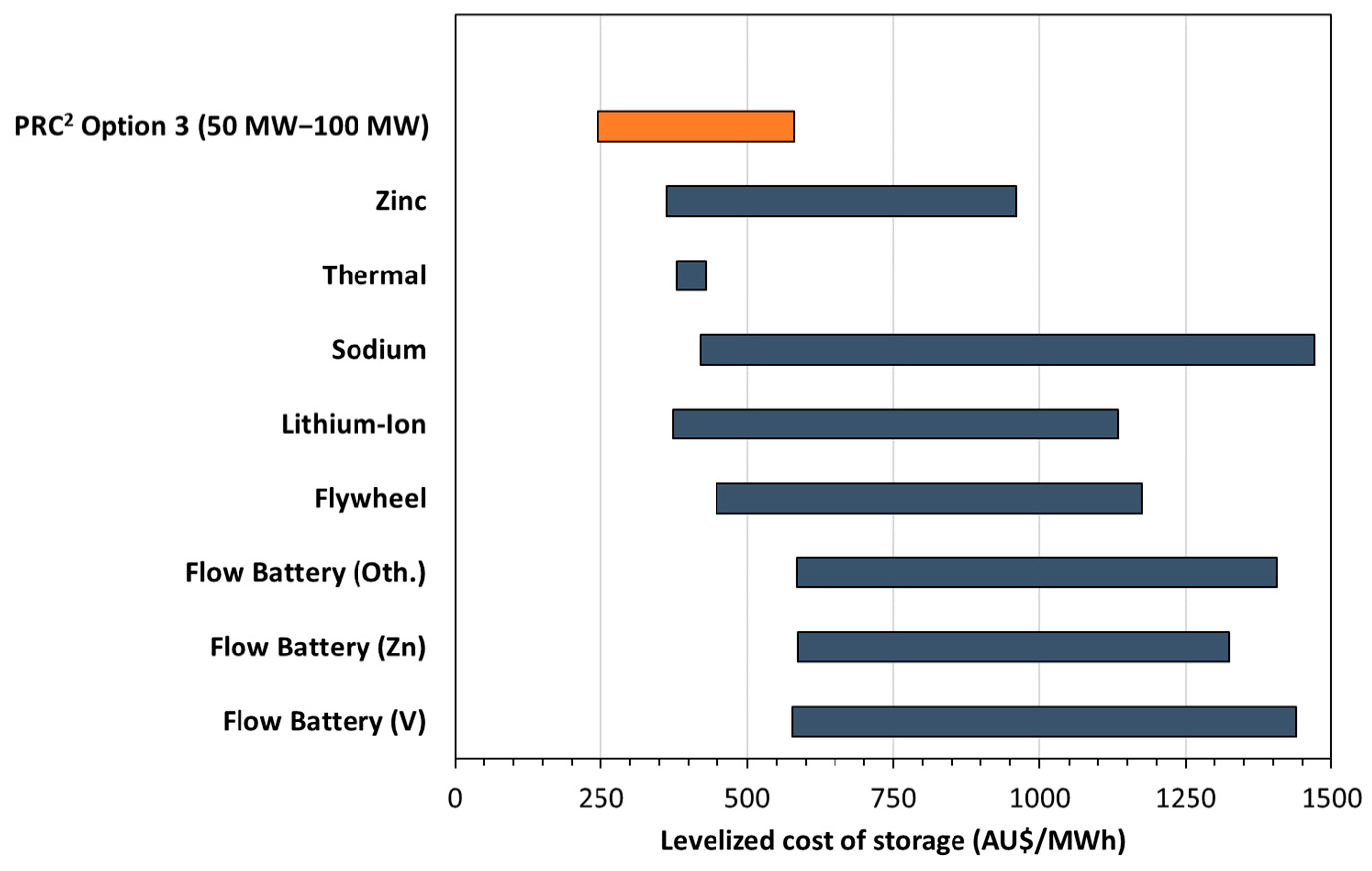
- Option 3—The same configuration as Option 1, except with the removal of the additional turbine used to recover energy from the stream exiting the CO2 storage vessel. Instead, a series of Joule–Thomson valves were implemented in the model.
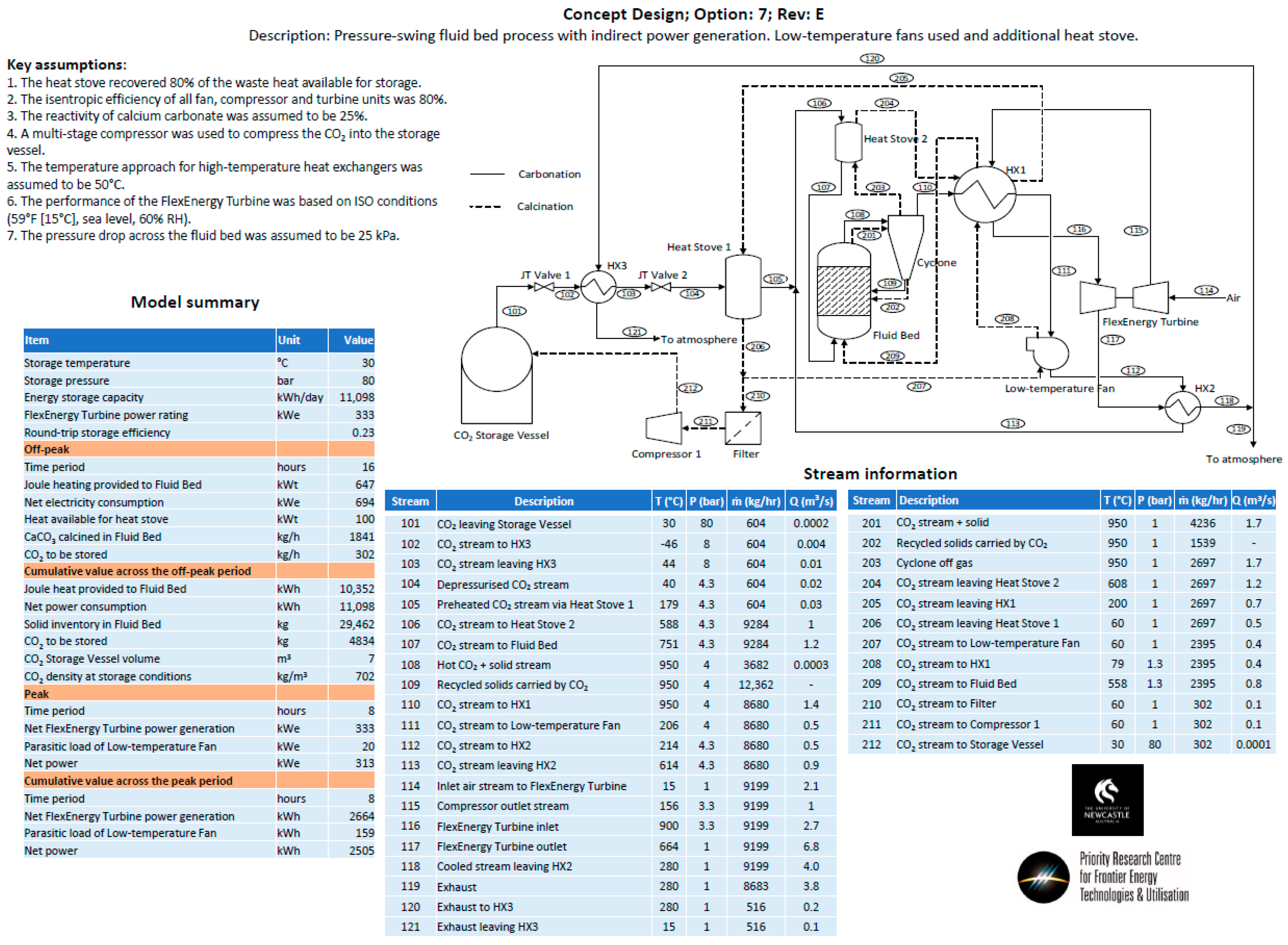
- Option 4—The same approach as Option 3, except the high-temperature fan has been replaced by low-temperature fan options.
- Option 5—The same approach as Option 4, except for the fact that it utilizes an additional heat stove.
- Option 6—The same approach as Option 4, except for the fact that it utilizes an alternate low-temperature fan configuration.
- Option 7—A pressure swing process with the same process configuration as Option 5. The temperature of the fluid bed was held at a constant temperature for both carbonation and calcination. The pressure of the fluid bed was changed between the carbonation (high pressure) and calcination cycles (low pressure).
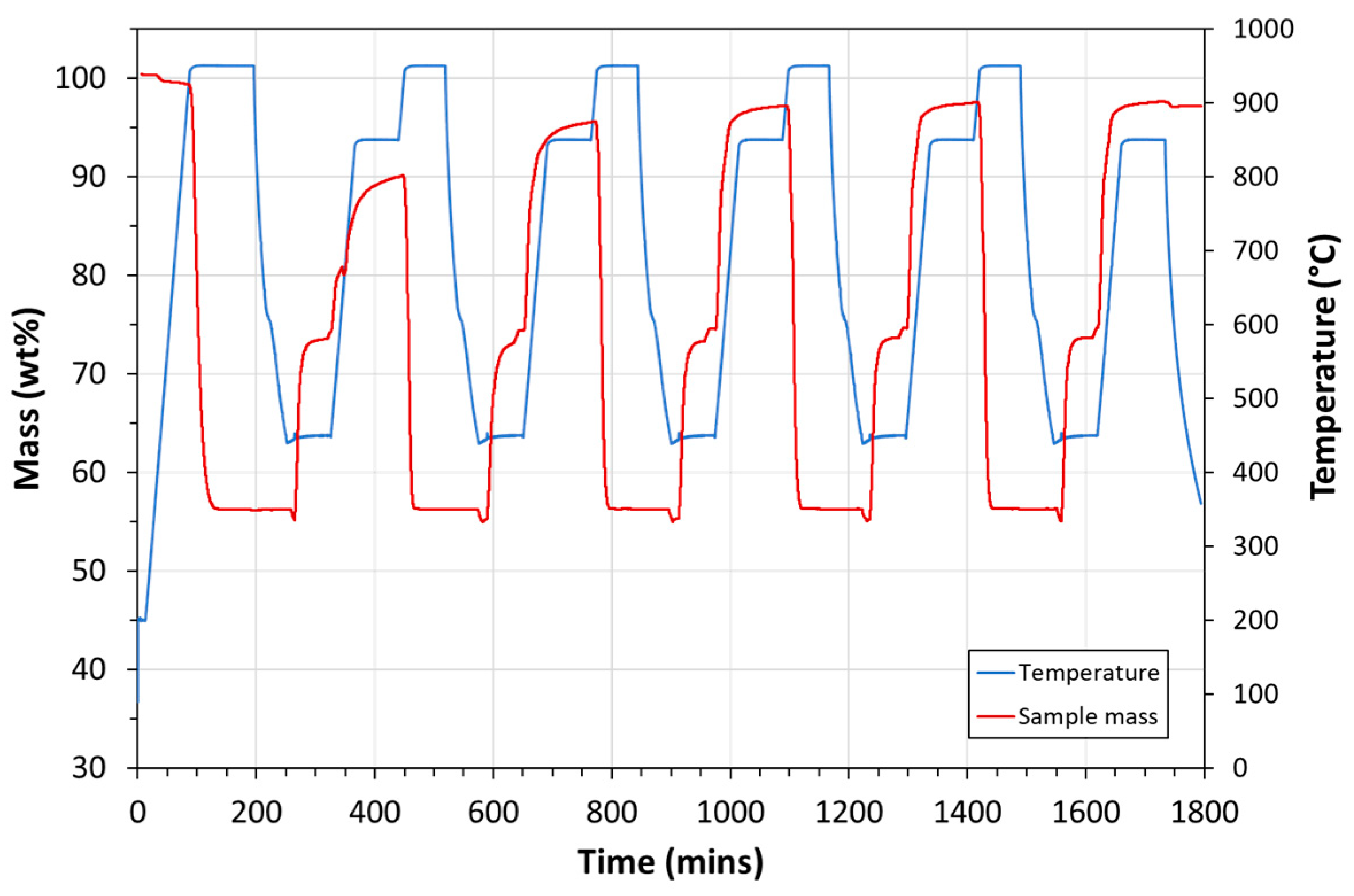
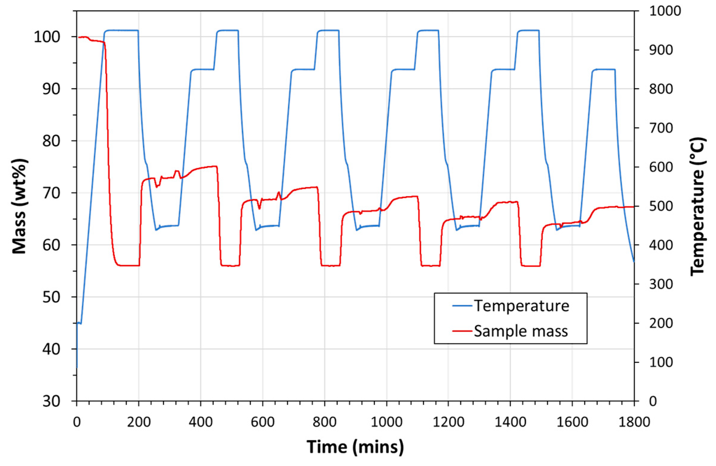
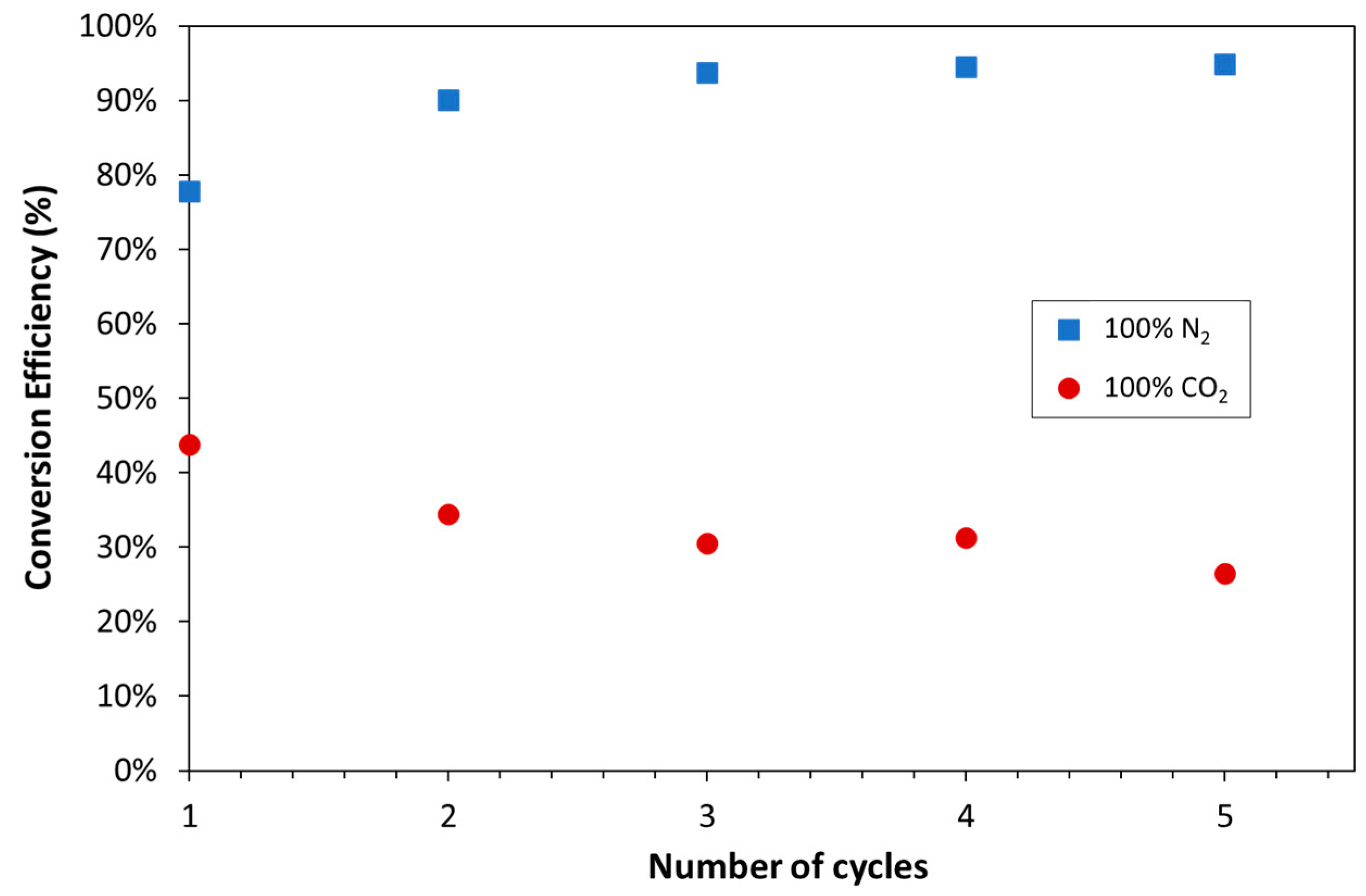
- Option 8—The same configuration as Option 3, but a hydration step was added between the calcination and carbonation steps. The hydration step aimed to improve the conversion efficiency of the carbonate material.
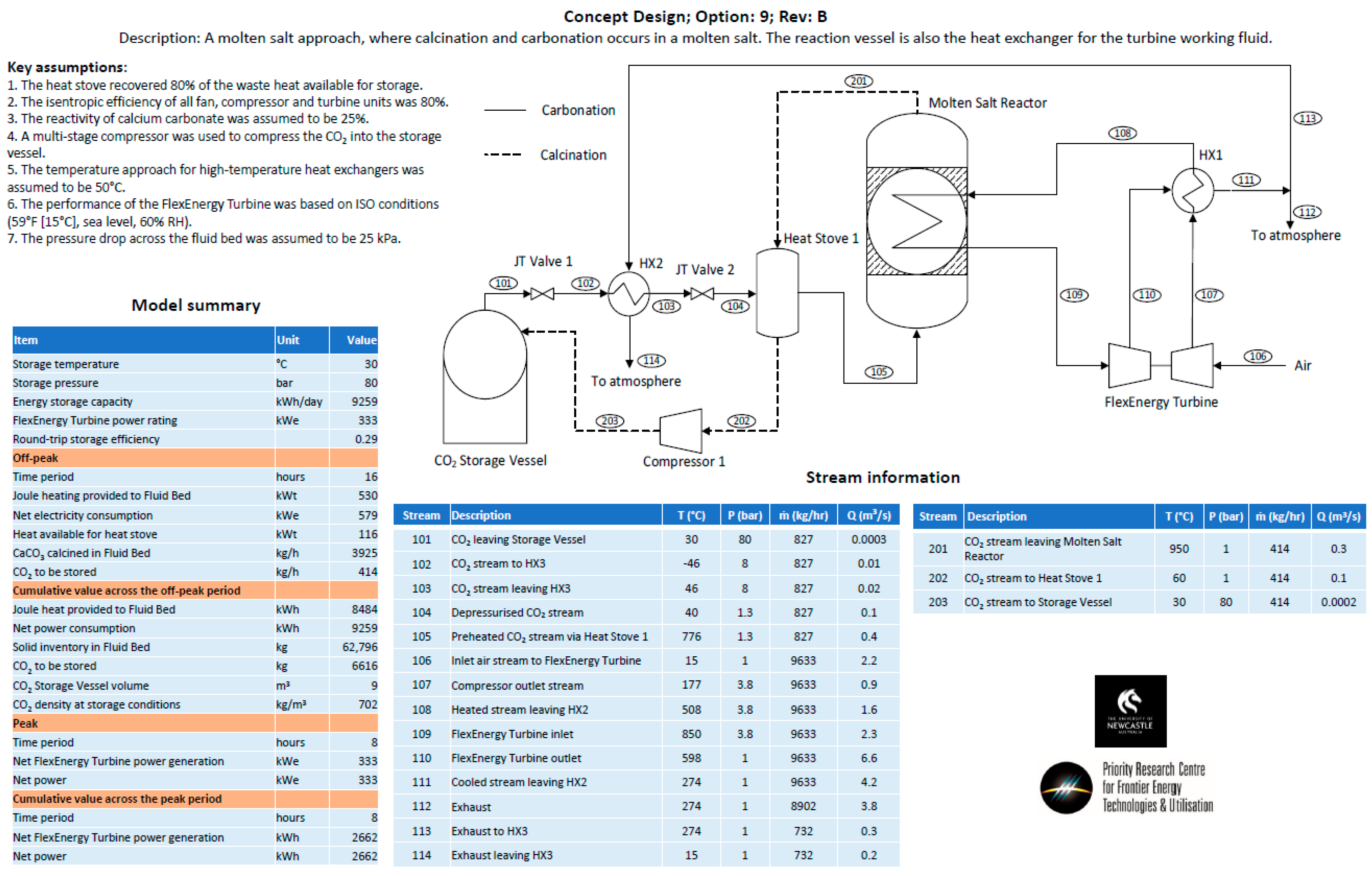
- Option 9—A molten salt approach, operating on the principle that the carbonate sorbent would be dissolved in a molten salt at up to 25 wt%. It was envisaged that the molten salt/carbonate mixture would be contained on the shell side of a shell-and-tube heat exchanger. During the carbonation phase, carbon dioxide would be bubbled through the shell side, while air would be passed through the tube side to increase the temperature of the air, and then passed directly through a turbine for power production. During the calcination phase, the shell-and-tube heat exchanger would be electrically heated, and CO2 released and passed through a heat stove before being compressed for storage in the CO2 storage vessel.
2.4. Process Modelling
2.5. Techno-Economic Analysis
3. Results and Discussion
3.1. Experimental
3.2. Process Modelling
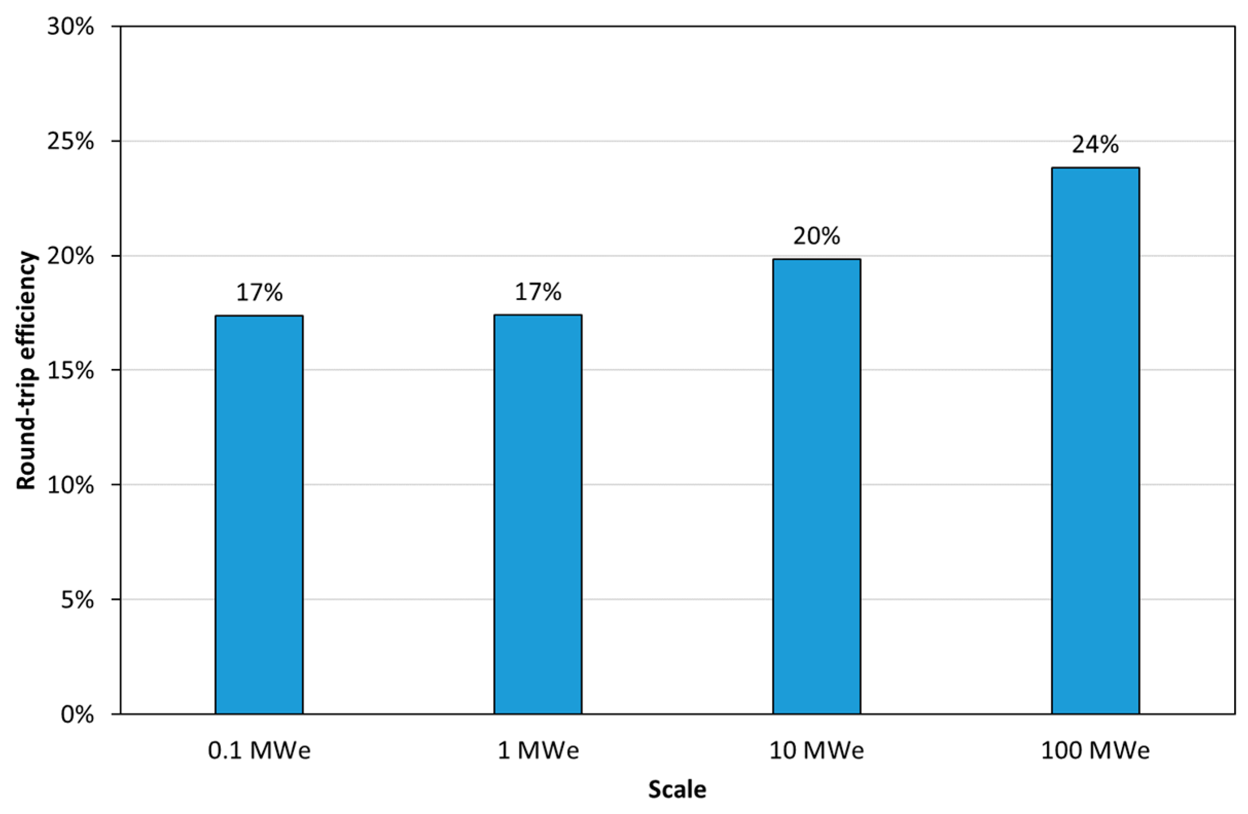
- The net output of the FlexEnergy turbine in a 1 MWt plant was 333 kW.
- Carbonation occurred at 850 °C.
- Calcination occurred at 950 °C.
- 100% CO2 was used for carbonation.
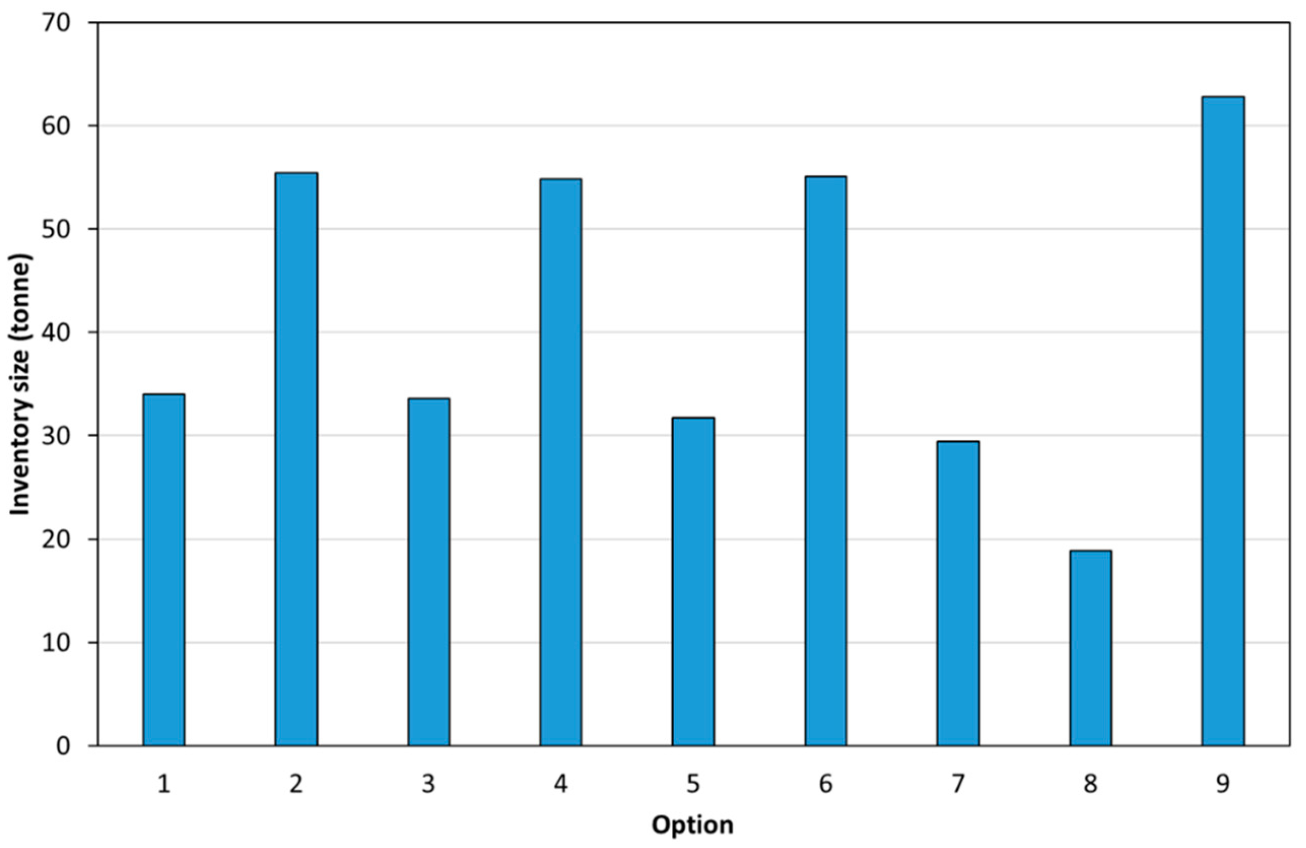
- Inventory size (i.e., the mass of calcium carbonate required): the inventory size determined the size of the fluid bed.
- Heat duties for the reactor (i.e., fluid bed or molten salt reactor), heat exchangers, and heat stoves.
- Round-trip efficiency of the PRC2 process.
3.3. Techno-Economic Assessment
4. Conclusions
Author Contributions
Funding
Data Availability Statement
Acknowledgments
Conflicts of Interest
Appendix A
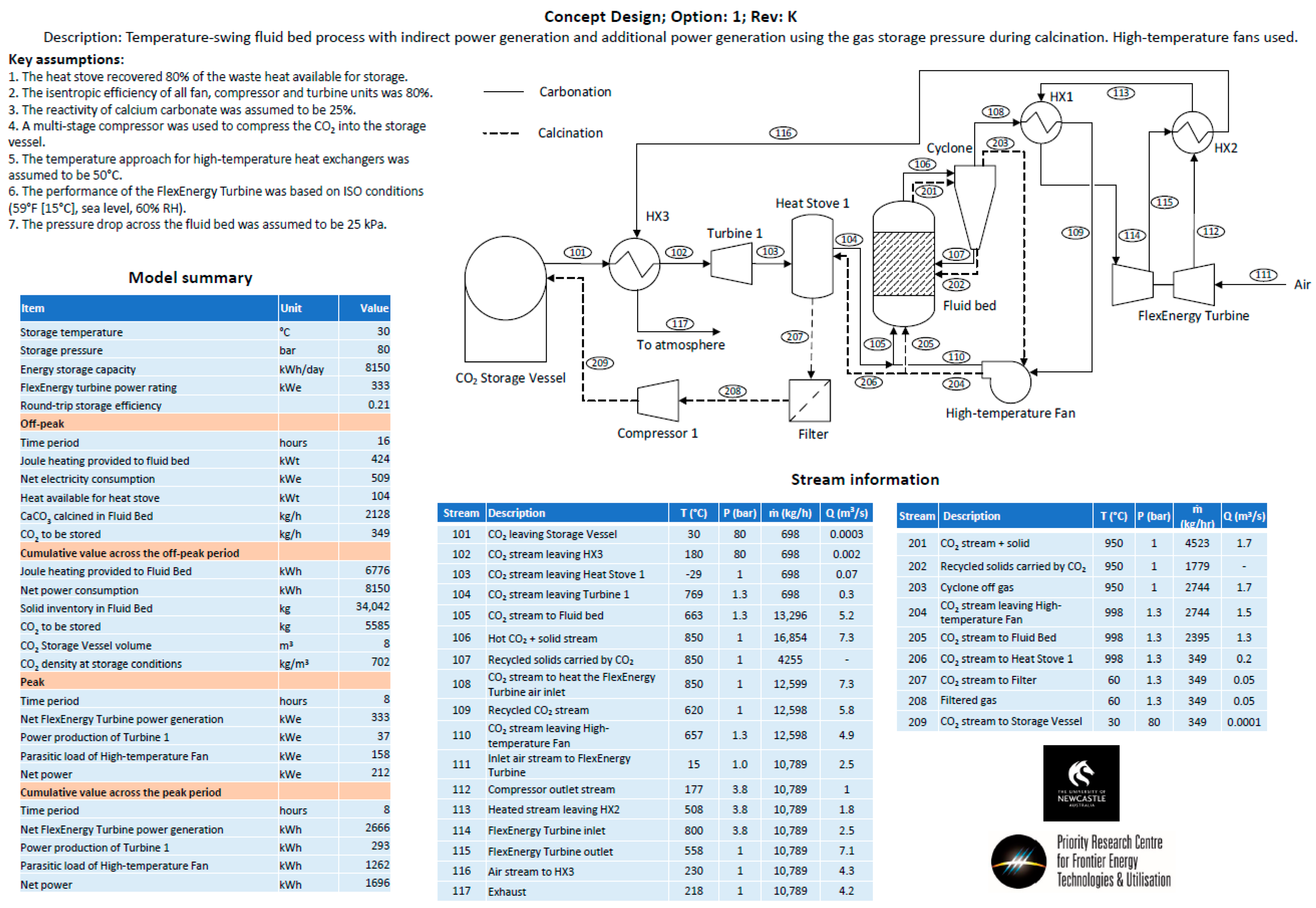

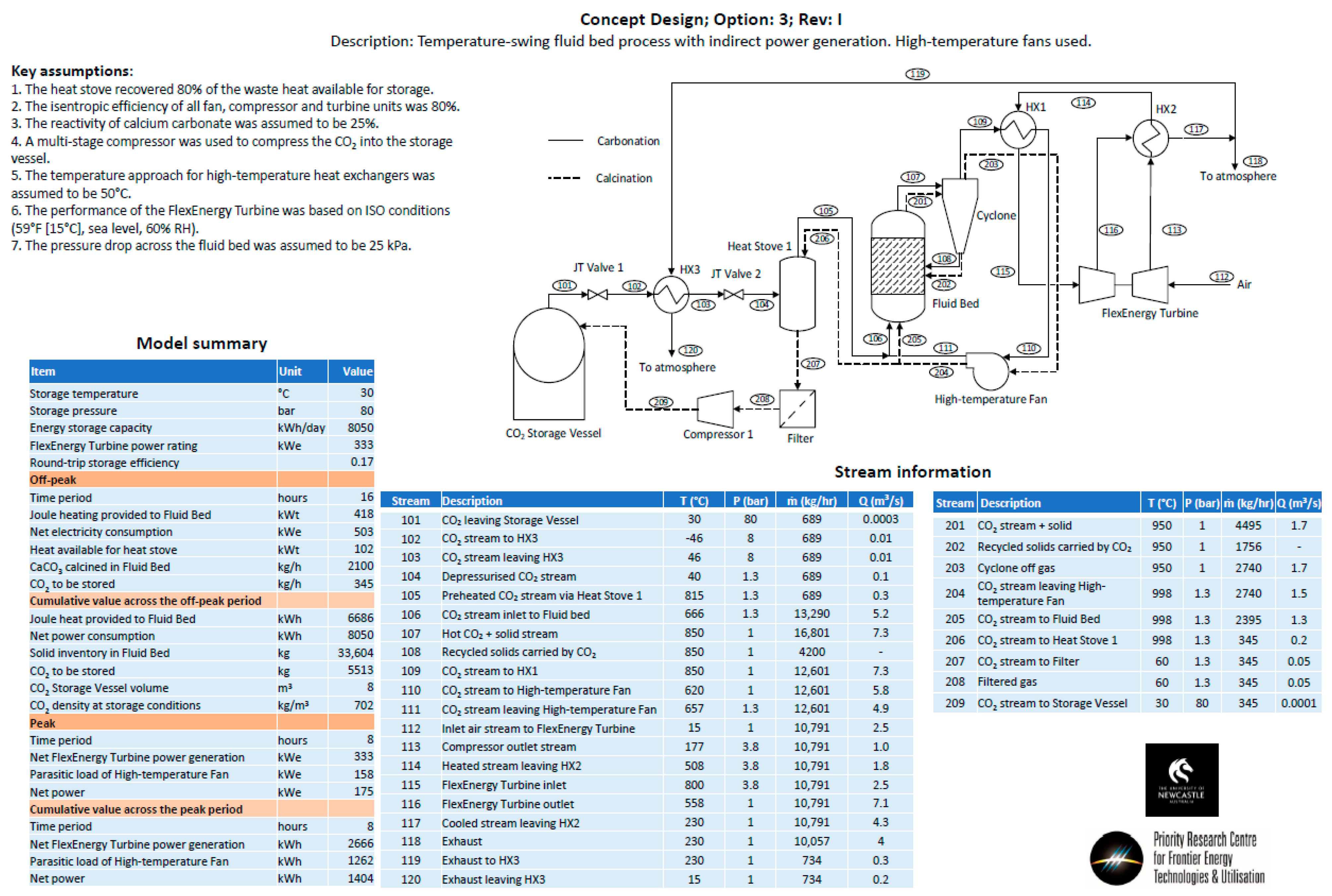

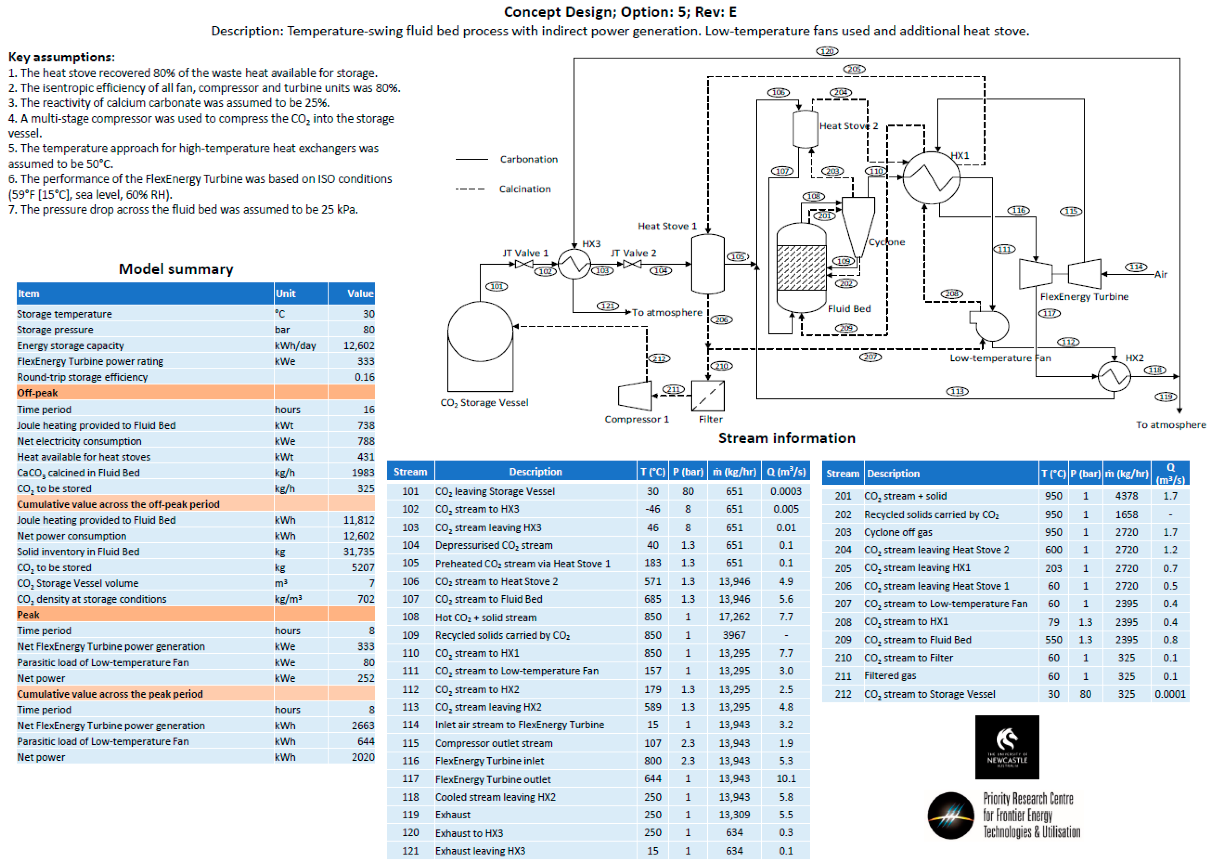
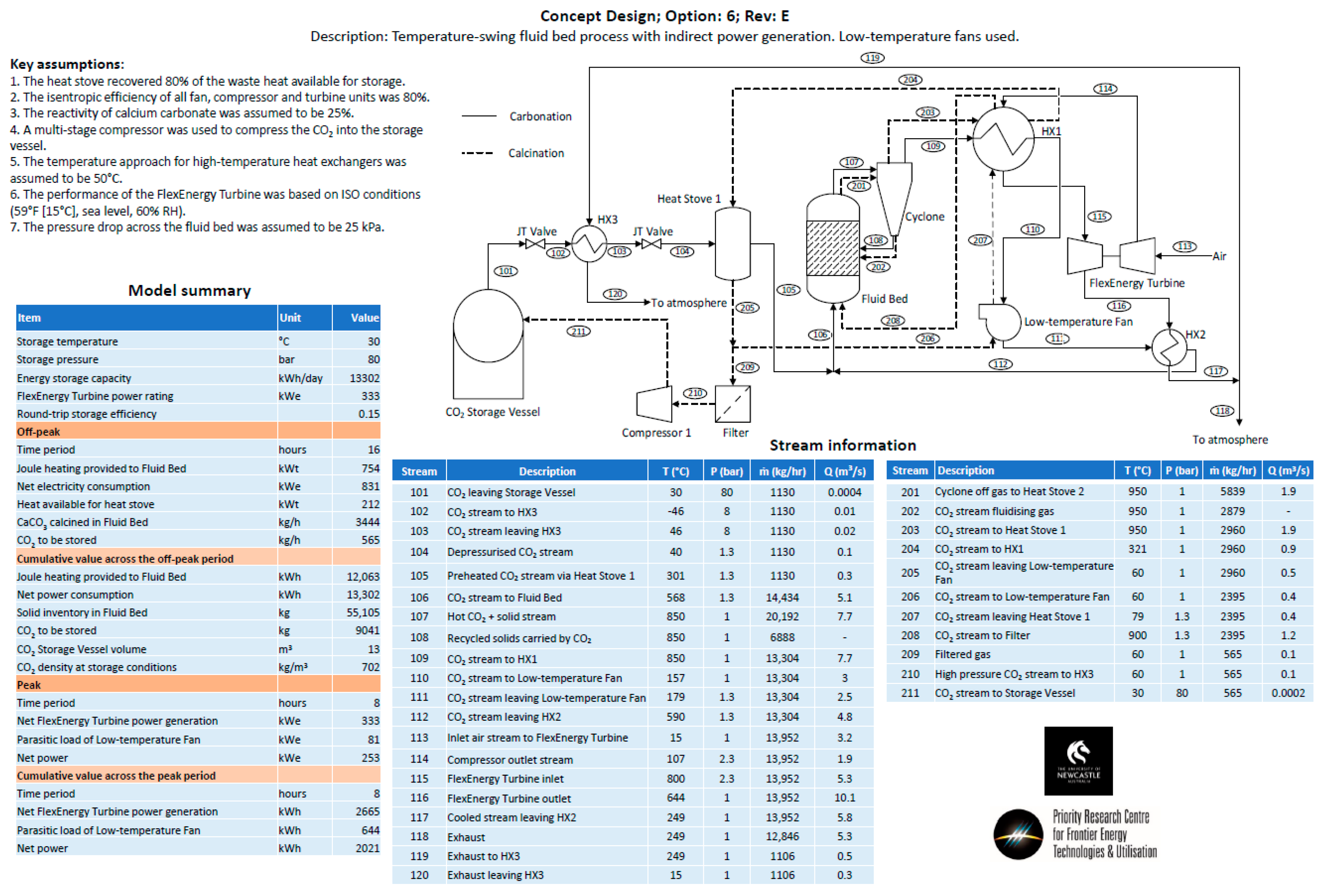
Appendix B
| No. | Equipment | Method of Sizing | Scaling Equation | Assumptions | Reference |
|---|---|---|---|---|---|
| 1 | CO2 Storage Tank | Shell mass, m (kg) | 11,600 + 34 × m0.85 |
|
|
| 2 | Compressor | Average exponent | 335,000 × (m/484)0.65 |
|
|
| 3 | Filter | - | - |
|
|
| 4 | Heat Stoves | MATLAB code to find number of heat stoves and shell mass, m (kg) for cost estimation | no. of heat stoves × (11,600 + 34 × m0.85) |
|
|
| 5 | Heat exchangers | Heat transfer area, A (ft2) | 1.218 × fd fm fp Cb | For:
| |
| 6 | CO2 turbines | Power, HP (hp) | 0.378 × (HP)0.62 |
|
|
| 7 | Fan | Number of fans based on the estimated pressure drop at process temperature | no. of fans × ΔP |
|
|
| 8 | Cyclone | Mass flow to cyclone | - |
|
|
| 9 | Reactor | Cross section area, A (m2) for fluidized bed options/Rule of thumb estimation for Molten Salt option | 4,600,000 × (A/10)0.25 |
| |
| 10 | Heating elements | Duty (kW)/No. of heating elements | C × (heat duty/500)n C × (no. elem./48)n |
|
|
References
- Mirmoghtadaei, G.; Mehrpooya, M.; Mahmoudi, M.; Ganjali, M.R. Integration of CaO/CaCO3-CaCl2 thermochemical energy storage system with solid oxide iron-air redox battery. Energy Convers. Manag. 2023, 290, 117213. [Google Scholar] [CrossRef]
- Zheng, H.; Liu, X.; Xuan, Y.; Ding, Y.; Flamant, G. Efficient direct solar-driven thermochemical energy storage of (AlMgFeMn)OxCaCO3 pellets in a fluidized bed reactor. Energy Convers. Manag. 2023, 285, 116990. [Google Scholar] [CrossRef]
- Xu, Q.; Wang, L.; Li, Z.; Shi, L. A calcium looping system powered by renewable electricity for long-term thermochemical energy storage, residential heat supply and carbon capture. Energy Convers. Manag. 2023, 276, 116592. [Google Scholar] [CrossRef]
- Wu, S.; Zhou, C.; Tremain, P.; Doroodchi, E.; Moghtaderi, B. A phase change calcium looping thermochemical energy storage system based on CaCO3/CaO-CaCl2. Energy Convers. Manag. 2021, 227, 113503. [Google Scholar] [CrossRef]
- Wu, S.; Zhou, C.; Doroodchi, E.; Moghtaderi, B. Techno-economic analysis of an integrated liquid air and thermochemical energy storage system. Energy Convers. Manag. 2020, 205, 112341. [Google Scholar] [CrossRef]
- Wu, S.; Zhou, C.; Doroodchi, E.; Moghtaderi, B. Thermodynamic analysis of a novel hybrid thermochemical-compressed air energy storage system powered by wind, solar and/or off-peak electricity. Energy Convers. Manag. 2019, 180, 1268–1280. [Google Scholar] [CrossRef]
- Materic, V.; Smedley, S.I. High Temperature Carbonation of Ca(OH)2. Ind. Eng. Chem. Res. 2011, 50, 5927–5932. [Google Scholar] [CrossRef]
- Kunii, D.; Levenspiel, O. CHAPTER 6—Bubbling Fluidized Beds. In Fluidization Engineering, 2nd ed.; Butterworth-Heinemann: Boston, MA, USA, 1991; pp. 137–164. [Google Scholar]
- Towler, G.; Sinnott, R. Chemical Engineering Design, 2nd ed.; Butterworth-Heinemann: Boston, MA, USA, 2012. [Google Scholar]
- Julch, V. Comparison of electricity storage options using levelised cost of storage (LCOS) method. Appl. Energy 2016, 183, 1594–1606. [Google Scholar] [CrossRef]
- Valverde, J.M.; Perejon, A.; Medina, S.; Perez-Maqueda, L.A. Thermal decomposition of dolomite under CO2: Insights from TGA and in situ XRD analysis. Phys. Chem. Chem. Phys. 2015, 17, 30162–30176. [Google Scholar] [CrossRef] [PubMed]
- González, B.; Grasa, G.S.; Alonso, M.; Abanades, J.C. Modeling of the Deactivation of CaO in a Carbonate Loop at High Temperatures of Calcination. Ind. Eng. Chem. Res. 2008, 47, 9256–9262. [Google Scholar] [CrossRef]
- Bhatia, S.K.; Perlmutter, D.D. Effect of the product layer on the kinetics of the CO2-lime reaction. AIChE J. 1983, 29, 79–86. [Google Scholar] [CrossRef]
- Abanades, J.C.; Alvarez, D. Conversion Limits in the Reaction of CO2 with Lime. Energy Fuels 2003, 17, 308–315. [Google Scholar] [CrossRef]
- Sun, R.; Li, Y.; Liu, H.; Wu, S.; Lu, C. CO2 capture performance of calcium-based sorbent doped with manganese salts during calcium looping cycle. Appl. Energy 2012, 89, 368–373. [Google Scholar] [CrossRef]
- Lysikov, A.I.; Salanov, A.N.; Okunev, A.G. Change of CO2 Carrying Capacity of CaO in Isothermal Recarbonation−Decomposition Cycles. Ind. Eng. Chem. Res. 2007, 46, 4633–4638. [Google Scholar] [CrossRef]
- Broda, M.; Pacciani, R.; Müller, C.R. CO2 Capture via Cyclic Calcination and Carbonation Reactions. In Porous Materials for Carbon Dioxide Capture; Lu, A.-H., Dai, S., Eds.; Springer: Berlin/Heidelberg, Germany, 2014; pp. 181–222. [Google Scholar]
- Valverde, J.M.; Medina, S. Crystallographic transformation of limestone during calcination under CO2. Phys. Chem. Chem. Phys. 2015, 17, 21912–21926. [Google Scholar] [CrossRef] [PubMed]
- Chacartegui, R.; Alovisio, A.; Ortiz, C.; Valverde, J.M.; Verda, V.; Becerra, J.A. Thermochemical energy storage of concentrated solar power by integration of the calcium looping process and a CO2 power cycle. Appl. Energy 2016, 173, 589–605. [Google Scholar] [CrossRef]
- Valverde, J.M. Ca-based synthetic materials with enhanced CO2 capture efficiency. J. Mater. Chem. A 2013, 1, 447–468. [Google Scholar] [CrossRef]
- Manovic, V.; Anthony, E.J. Carbonation of CaO-Based Sorbents Enhanced by Steam Addition. Ind. Eng. Chem. Res. 2010, 49, 9105–9110. [Google Scholar] [CrossRef]
- Donat, F.; Florin, N.H.; Anthony, E.J.; Fennell, P.S. Influence of High-Temperature Steam on the Reactivity of CaO Sorbent for CO2 Capture. Environ. Sci. Technol. 2012, 46, 1262–1269. [Google Scholar] [CrossRef] [PubMed]
- Lazard. Lazard’s Levelized Cost of Storage Analysis, version 3.0; 2017. Available online: https://www.actu-environnement.com/media/pdf/news-29972-etude-cout-stockage-lazard.pdf (accessed on 26 July 2018).
- Couper, J.R.; Penney, W.R.; Fair, J.R.; Walas, S.M. Chemical Process Equipment-Selection and Design, 2nd ed.; Elsevier: Amsterdam, The Netherlands, 2009. [Google Scholar]
- Branan, C.R. Rules of Thumb for Chemical Engineers: A Manual of Quick, Accurate Solutions to Everyday Process Engineering Problems; Elsevier: Amsterdam, The Netherlands, 2002. [Google Scholar]
- Woods, D.R. Rules of Thumb in Engineering Practice; Wiley & Sons: Hoboken, NJ, USA, 2007. [Google Scholar]





| Exp. No. | Reaction Temperature (˚C) | Gas Mixture (mol %) | Pressure (bar) | No. of Cycles | Carbonate Material | |||||
|---|---|---|---|---|---|---|---|---|---|---|
| Calc. | Carb. | Hyd. | Calc./Carb. | Hyd. | Calc. | Carb. | Hyd. | |||
| 1 | 900 | 850 | - | 100% CO2 | - | 1.2 | 1.2 | - | 5 | CaCO3 |
| 2 | 1000 | 850 | - | 100% CO2 | - | 1.2 | 1.2 | - | 5 | CaCO3 |
| 3 | 1000 | 850 | - | 100% CO2 | - | 1.2 | 1.2 | - | 50 | CaCO3 |
| 4 | 950 | 850 | - | 100% CO2 | - | 1.2 | 1.2 | - | 30 | CaCO3 |
| 5 | 950 | 850 | - | 50% CO2, 50% Air | - | 1.2 | 1.2 | - | 30 | CaCO3 |
| 6 | 900 | 800 | - | 50% CO2, 50% Air | - | 1.2 | 1.2 | - | 15 | CaCO3 |
| 7 | 850 | 750 | - | 25% CO2, 75% Air | - | 1.2 | 1.2 | - | 15 | CaCO3 |
| 8 | 950 | 850 | - | 100% CO2 | - | 1.2 | 1.2 | - | 30 | CaMg(CO3)2 |
| 9 | 900 | 800 | - | 50% CO2, 50% Air | - | 1.2 | 1.2 | - | 30 | CaMg(CO3)2 |
| 10 | 850 | 750 | - | 25% CO2, 75% Air | - | 1.2 | 1.2 | - | 30 | CaMg(CO3)2 |
| 11 | 950 | 950 | - | 100% CO2 | - | 1.2 | 4 | - | 5 | CaCO3 |
| 12 | 950 | 950 | - | 100% CO2 | - | 1.2 | 4 | - | 15 | CaCO3 |
| 13 | 950 | 850 | 450 | 100% CO2, N2 cooling | 90% H2O, 10% N2 | 1.2 | 1.2 | 2 | 5 | CaCO3 |
| 14 | 950 | 850 | 450 | 100% CO2, CO2 cooling | 90% H2O, 10% CO2 | 1.2 | 1.2 | 2 | 5 | CaCO3 |
| Sample | Composition (wt%) | ||||||||
|---|---|---|---|---|---|---|---|---|---|
| CaO | Al2O3 | SiO2 | MgO | Fe2O3 | MnO | TiO2 | K2O | Na2O | |
| CaCO3 | 98.52 | 0.37 | 1.06 | 0.81 | 0.31 | 0.03 | 0.088 | 0.053 | <0.01 |
| CaMg(CO3)2 | 38.15 | 3.7 | 31.67 | 22.55 | 1.87 | 0.04 | 0.29 | 0.14 | 1.05 |
| Assumptions | |
|---|---|
| 1 | Heat stoves recovered 80% of the waste heat available for storage |
| 2 | The isentropic efficiency of all fans, compressors, and turbines was 80% |
| 3 | The reactivity of calcium carbonate ranged from 25% for Options 1 to 7, to 60% for Option 8, and 75% for Option 9 |
| 4 | A multi-stage compressor was used to compress the CO2 into the storage vessel |
| 5 | The temperature approach for high-temperature heat exchangers: 50 °C |
| 6 | The performance of the FlexEnergy turbine was based on ISO conditions (59 °F [15 °C], sea level, 60% RH) |
| 7 | The pressure drop across the fluid bed was 25 kPa |
| 8 | Carbonation time (8 h) and calcination time (16 h), except for Option 8 (carbonation/calcination times of 8 h, with hydration/dehydration times of 4 h each) |
| 9 | Carbonation temperature 850 °C, calcination temperature 950 °C, hydration temperature 450 °C |
| Sample | Week | Specific Surface Area (m2/kg) | dSauter (µm) | d10 (µm) | d50 (µm) | d90 (µm) |
|---|---|---|---|---|---|---|
| Fresh | 0 | 61.6 | 98 | 165 | 288 | 471 |
| Sample 1 | 1 | 24.6 | 244 | 160 | 278 | 461 |
| Sample 2 | 2 | 23.9 | 252 | 163 | 282 | 464 |
| Sample 3 | 3 | 22.4 | 268 | 173 | 292 | 471 |
| Sample 4 | 4 | 21.8 | 275 | 180 | 297 | 475 |
| Sample 5 | 6 | 21.5 | 279 | 183 | 301 | 483 |
| Sample 6 | 8 | 22.7 | 265 | 171 | 287 | 467 |
| Sample 7 | 10 | 22.1 | 271 | 174 | 296 | 485 |
| Sample 8 | 12 | 22.9 | 262 | 167 | 287 | 476 |
Disclaimer/Publisher’s Note: The statements, opinions and data contained in all publications are solely those of the individual author(s) and contributor(s) and not of MDPI and/or the editor(s). MDPI and/or the editor(s) disclaim responsibility for any injury to people or property resulting from any ideas, methods, instructions or products referred to in the content. |
© 2024 by the authors. Licensee MDPI, Basel, Switzerland. This article is an open access article distributed under the terms and conditions of the Creative Commons Attribution (CC BY) license (https://creativecommons.org/licenses/by/4.0/).
Share and Cite
Moghtaderi, B.; Tremain, P.; Warner, J. Pressurized Regenerative Calcium Cycle for Utility-Scale Energy Storage: A Techno-Economic Assessment. Processes 2024, 12, 1778. https://doi.org/10.3390/pr12081778
Moghtaderi B, Tremain P, Warner J. Pressurized Regenerative Calcium Cycle for Utility-Scale Energy Storage: A Techno-Economic Assessment. Processes. 2024; 12(8):1778. https://doi.org/10.3390/pr12081778
Chicago/Turabian StyleMoghtaderi, Behdad, Priscilla Tremain, and John Warner. 2024. "Pressurized Regenerative Calcium Cycle for Utility-Scale Energy Storage: A Techno-Economic Assessment" Processes 12, no. 8: 1778. https://doi.org/10.3390/pr12081778
APA StyleMoghtaderi, B., Tremain, P., & Warner, J. (2024). Pressurized Regenerative Calcium Cycle for Utility-Scale Energy Storage: A Techno-Economic Assessment. Processes, 12(8), 1778. https://doi.org/10.3390/pr12081778


