Abstract
The conventional iron and steel industry (ISI), driven by coal utilization as its predominant feedstock, constitutes a substantial source of greenhouse gas emissions. Hydrogen metallurgy presents the opportunity to mitigate carbon emissions in ISI from the origin. Among hydrogen metallurgical approaches, the hydrogen-based direct reduction iron (H-DRI) process stands out for its substantial carbon reduction capabilities and established technological maturity. The present paper provides a comprehensive review of the development and application surrounding the H-DRI process. Firstly, the main chemical reactions of H-DRI and the relevant important parameters are introduced. Subsequently, an overview is provided of several prominent H-DRI processes, including HYL, Midrex, Midrex-H2®, HYL-III, HYL-ZR, BL, and Finmet, elucidating their characteristics through comparative analysis. Moreover, some research results of H-DRI process optimization are summarized. Leveraging insights garnered from globally representative projects exemplifying the industrial deployment of H-DRI technology in recent years, the trajectory of and prospective trends for industrial development in the field of H-DRI processes are explored. Further, prevailing challenges and impediments encountered in the adoption of H-DRI processes are identified, culminating in strategic recommendations tailored towards fostering future advancements. In the long term, the H-DRI process is expected to become a key path to achieve ISI cleaner production.
1. Introduction
As a crucial foundational sector in economic and social development, the ISI has experienced rapid growth over the past few decades [1]. At the same time, the ISI is also a high-energy-consumption and high-carbon-emissions industry. At present, the annual global output of crude steel has reached about 1.9 billion tons [2], with an average energy intensity of 20 GJ [3] and carbon dioxide emissions ranging from 1.8 to 2.0 tons per ton of crude steel [4,5]. The ISI is a contributor of 8% of the world’s total energy consumption and 7–9% of total carbon dioxide emissions [6,7]. With the escalating concerns surrounding global warming and environmental degradation stemming from excessive carbon dioxide emissions [8], carbon reduction and decarbonization have emerged as prominent subjects in contemporary research on the ISI.
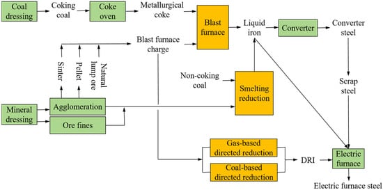
In the ISI, approximately 80% of carbon dioxide emissions are closely associated with traditional ironmaking processes characterized by high coal consumption [9]. Figure 1 shows the analysis of the whole process of modern steel production. Ironmaking involves four main production processes, including blast furnace reduction, smelting reduction, gas-based direct reduction, and coal-based direct reduction [10]. An observation can be made that except for the gas-based direct reduction process, coal is used as the main raw material in the remaining three ironmaking processes. In particular, the blast furnace–basic oxygen furnace (BF-BOF) process, which accounts for production of 70% of the world’s total steel output, consumes a large amount of metallurgical coke as fuel and reducing agent in the ironmaking process [11,12].
In comparison to the current ironmaking process reliant on coal as the primary raw material, hydrogen metallurgy offers the possibility to significantly reduce carbon emissions at the source, thereby enabling the low-carbon production of steel [13,14,15]. Hydrogen is a clean energy with advantages such as a wide range of sources, fast chemical reaction, high calorific value, and satisfactory thermal conductivity [16]. The gaseous byproduct resulting from the reduction reaction between hydrogen and iron oxide is primarily water, thus effectively mitigating carbon emissions in the reduction of iron ore [17]. Currently, the routes of hydrogen metallurgy mainly include blast furnace hydrogen-rich reduction [18,19], hydrogen-based smelting reduction [20], and hydrogen-based direct reduction [21,22]. Due to the irreplaceable skeleton role of coke in the blast furnace, the maximum carbon emission reduction for the blast furnace hydrogen-rich reduction process can reach only 20–30% under current technical conditions [23]. Additionally, the advancement of hydrogen-based smelting reduction is still in its nascent stages. Despite its considerable potential for reducing carbon emissions, it is currently deemed premature for widespread industrial application [24]. In contrast, hydrogen-based direct reduction not only delivers a significant carbon reduction effect, but also is more feasible. In a study conducted by Li et al. [25], it was found that compared with the 2054.33 kg of carbon emissions per ton of steel in the BF–BOF process, the hydrogen-rich shaft furnace–electric arc furnace process based on coal gasification and the pure-hydrogen shaft furnace–electric arc furnace process based on renewable power and water electrolysis resulted in reduced carbon emissions of 1121.28 kg and 120.92 kg per ton of steel, respectively. Research by Abhina et al. [21] showed that the hydrogen direct reduction iron ore–electric arc furnace process could reduce the carbon emissions from steel production in the European Union by more than 35%. Moreover, the H-DRI process achieved a certain level of industrial production maturity [26]. As such, the H-DRI process is considered one of the most promising hydrogen metallurgy processes.
Presently, H-DRI has been widely considered and studied in the ISI. Wang et al. [26] proposed that pure-hydrogen direct reduction is the technology with the most potential to realize low-carbon steelmaking. Their exploration of the topic encompassed a comprehensive analysis of the technology from the vantage point of hydrogen production and process feasibility. Notably, they noted that the economic feasibility of pure-hydrogen direct reduction in the short term was seriously limited by the preparation cost of green hydrogen. In addition, challenges pertaining to process efficiency and the generation of carbon-free products were identified as critical issues requiring resolution. The direct reduction process using a hydrogen-rich shaft furnace was determined as the key transition technology. The two main hydrogen-based shaft furnace processes, Midrex and HYL/Energiron, were briefly introduced, and the energy consumption under different ratios of natural gas and hydrogen was compared. In the long run, the progressive reduction in the cost of green hydrogen production and ongoing process enhancements may facilitate the incremental increase in hydrogen content in the hydrogen-rich shaft furnace. Consequently, the eventual actualization of pure-hydrogen direct reduction may become feasible. Liu et al. [27] introduced several major different hydrogen production technologies and reviewed the applications of hydrogen in steel production, including the blast furnace process, direct reduction process, and molten reduction process. Their analysis culminated in the assertion that the H-DRI process is poised to become an important complement to the BF process. Additionally, they underscored the imperative of achieving breakthroughs in key H-DRI process technologies. Spreitzer et al. [28] provided a detailed review and analysis of the thermodynamics and kinetics inherent in the hydrogen reduction of iron oxide. Their study delved into investigating the impact of various parameters, such as iron oxide type and temperature, on the reduction process of iron oxide, with comparative reference to the CO reduction process. Furthermore, they demonstrated the rationale behind utilizing different methods to elucidate reduction dynamics. Cavaliere [29] also studied and summarized the thermodynamics and kinetics of hydrogen direct reduction of iron ore and gave a detailed formula for calculating the reaction rate. Fradet et al. [30] summarized and compared the experimental studies and results of a large number of hydrogen-reduction iron oxide particles and found that the reaction kinetic model still needs to be further improved.
In summary, many scholars have studied and discussed the basic theory of hydrogen direct reduction of iron oxide, and some have discussed the feasibility and carbon emission reduction potential of the H-DRI process or introduced and compared some aspects of different H-DRI processes. However, a comprehensive analysis and comparative and optimization summary of H-DRI processes are currently lacking in the literature, which is essential to facilitate the industrial application of H-DRI processes. It is essential for different countries or regions to choose an H-DRI process that aligns with the characteristics of their own resources and development goals. In the present paper, with a focus on the H-DRI process, the development and application of the H-DRI process are comprehensively introduced in terms of its main chemical reactions, typical processes and characteristics, process optimization, and representative industrialization projects. Moreover, the current problems and challenges in the H-DRI process are discussed, followed by suggestions for the future development direction of the H-DRI process. This paper aims to provide a relatively comprehensive reference for H-DRI research and accelerate the development of the H-DRI process, thus catalyzing the green and low-carbon transformation of the ISI.
2. Main Chemical Reactions in the H-DRI Process
The H-DRI process primarily entails the utilization of pure hydrogen or hydrogen-rich gases, such as H2 or H2–CO mixed gas, as well as natural gas or coke oven gas, for the reduction reaction with iron ore below its melting temperature. The resultant solid product is referred to as direct reduction iron (DRI) [21,31,32]. Because of its porous structure, DRI is also known as sponge iron [33]. In this section, the main chemical reactions in the H-DRI process and the relevant important parameters are introduced.
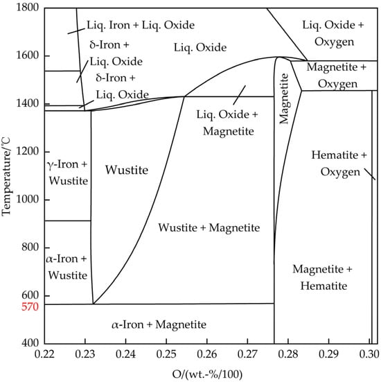
Existing research has demonstrated that the generation of DRI in the reduction reaction between hematite (Fe2O3) and H2/CO involves several stages [34,35,36,37,38,39]: First, hematite is reduced to magnetite (Fe3O4). Subsequently, at 570 °C, a critical temperature is reached, determining the progression of the subsequent steps in the reduction reaction. If the temperature is >570 °C, the magnetite is gradually reduced to a Wüstite (Fe1−xO) which is further reduced to iron. If the temperature is <570 °C, magnetite is directly reduced to iron. The chemical reaction formulas for the reduction of iron oxide with H2 and CO are shown in Formulas (1)–(8). Figure 2 presents a Fe–O binary phase diagram. An observation can be made that the Wüstite can only exist stably at a temperature above 570 °C, and will decompose into Fe3O4 and Fe when the temperature is below 570 °C. Since there are vacancies in the ferrite crystal lattice of the Wüstite, the chemical formula of the Wüstite should actually be Fe1−xO [28,40]. For simplicity, the Wüstite is represented by FeO below.
Chemical reaction formulas of Fe2O3 → Fe with H2:
T > 570 °C:
T < 570 °C:
Chemical reaction formulas of Fe2O3 → Fe with CO:
T > 570 °C:
T < 570 °C:
Table 1 shows the calculated thermodynamic parameters of the reduction of iron oxide with H2/CO, including Gibbs free energy, enthalpy change, and equilibrium constant [41]. An observation can be made that except for the first stage (Fe2O3 → Fe3O4) which involved an exothermic reaction, all of the remaining stages involved endothermic reactions in the reduction of hematite with H2. Regarding the reduction of hematite with CO, except for the second stage (Fe3O4 → FeO) which involved an endothermic reaction, all of the remaining stages involved exothermic reactions. Overall, the reduction of hematite with CO to DRI involved an exothermic reaction, while the reduction of hematite with H2 to DRI involved an endothermic reaction. Additionally, through calculation of the linear relationship between the Gibbs free energy generated by iron oxides and reducing gas oxides and the temperature, if the temperature is >570 °C, the stability sequence of iron oxides is as follows: FeO > Fe3O4 > Fe2O3. That is, FeO is the most stable and the most difficult to reduce.
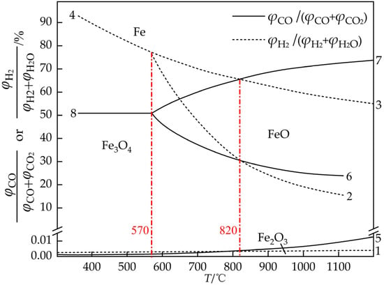
Figure 3 shows the equilibrium diagram of the reduction of iron oxide with H2/CO. The horizontal axis represents the temperature, while the vertical axis denotes the gas oxidation degree (GOD). A lower GOD indicates a stronger reduction capacity of the mixed gas. Curves 1–8 correspond to chemical reaction Formulas (1)–(8), where the solid line represents the reduction with CO at all stages, and the dotted line represents the reduction with H2 at all stages. An observation can be made that as the temperature increases, the stability interval of Fe becomes larger with H2 as the reducing agent, indicating that increasing the temperature is conducive to the reduction with H2. When CO is used as reducing agent, the stability interval of Fe is much greater at relatively low temperatures. Hence, an appropriate decrease in temperature is conducive to improving the utilization rate of CO gas. In the first stage of reduction with H2/CO (Fe2O3 → Fe3O4, curve 5/curve 1), GOD is close to zero in the equilibrium state, suggesting that a weak reduction can lead to an Fe2O3 → Fe3O4 reaction. When the temperature is >570 °C, comparing the GOD of the second stage of reduction with H2/CO (Fe3O4 → FeO, curve 3/curve 7) and that of the third stage of reduction with H2/CO (FeO → Fe, curve 2/curve 6), it is observed that a higher concentration of reducing gas is required for the FeO → Fe reaction. This suggests that FeO is more resistant to reduction. Notably, curve 2 representing the reduction of FeO with H2 and curve 6 depicting the reduction of FeO with CO intersected at 820 °C, marking another key temperature in the H-DRI process. Subsequently, as the temperature increases further, the GOD of the reduction of FeO with H2 begins to be lower than that of the reduction of FeO with CO. This implies that when the temperature exceeds 820 °C, the reduction capacity of H2 surpasses that of CO [9,42]. Therefore, in order to give full play to the advantages of the rapid reaction rate of hydrogen-reduced iron ore, the reduction reaction temperature should be controlled above 820 °C.
3. Typical H-DRI Processes
DRI is a high-quality raw material for steelmaking with an electric arc furnace [43]. The DRI obtained via the hydrogen-based direct reduction process is further refined in the electric arc furnace together with the scrap steel. The H-DRI process not only mitigates carbon emissions within the ISI but also holds significant importance in advancing short-process steel smelting techniques and enhancing the energy structure of the ISI [10,44]. There are three main types of equipment for the H-DRI process: a tank furnace, shaft furnace, and fluidized bed. In this section, several typical processes are introduced, followed by a summarization of their characteristics and key parameters.
3.1. Direct Reduction Process with Tank Furnace
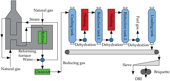
The HYL process (HYL-I, HYL-II), featuring tank furnaces, once constituted a significant portion of DRI production, marking a milestone in the industrialization of modern DRI [10,45]. However, this process has lagged behind modern metallurgical technologies due to its non-continuous production, gradually being supplanted by direct reduction processes employing shaft furnaces. Figure 4 illustrates the workflow of the HYL direct reduction process.
In the HYL process, the primary equipment comprises the natural gas reforming furnace and the reaction tank. The natural gas reforming furnace serves to produce reducing gas. Utilizing Kellogg’s water vapor reforming technology, CH4 and H2O undergo catalytic cracking reactions at 850 °C, yielding H2 and CO. Following heat transfer and purification processes, the resulting cold reducing gas boasts an H2 content of up to 75% [45].
There are generally four reaction tanks, including a cooling tank, main reduction tank (reduction tank 1), secondary reduction tank (reduction tank 2), and loading and unloading tank depending on the operating conditions. The upper part of each tank is provided with a loading port and a reducing gas inlet, and their lower part is provided with a discharge port and an exhaust gas outlet. The four reaction tanks operate in alternation, with each reduction tank undergoing five stages within one working cycle: loading, pre-reduction, reduction, cooling, and unloading. In every operational cycle, the tank involved in loading or unloading materials is designated as the loading or unloading tank. Subsequent to loading or unloading, the tank transitions into a secondary reduction tank, while the original secondary reduction tank assumes the role of the main reduction tank, and the original main reduction tank becomes the cooling tank.
The cooling gas utilized in the cooling tank consists of the washed cold reducing gas. Following the cooling and dehydration processes, the discharged reducing gas is heated to form high-temperature reducing gas, subsequently introduced into the main reducing tank to facilitate the reduction of iron ore into direct reduced iron. The exhaust gas discharged from the main reduction tank is dehydrated and heated and enters the secondary reduction tank to preheat and pre-reduce the ore. Finally, the exhaust gas discharged from the secondary reduction tank is dehydrated and used as fuel for the reducing gas heating furnace.
3.2. Direct Reduction Process with Shaft Furnace
The direct reduction process with a shaft furnace involves the reduction of iron ore utilizing high-temperature reducing gas within the shaft furnace. Known for its high efficiency and substantial output, this method stands as the foremost DRI production process globally at present. The following is a description of five typical direct reduction processes with a shaft furnace, including Midrex, Midrex-H2®, HYL-III, HYL-ZR, and BL.
3.2.1. Midrex Process
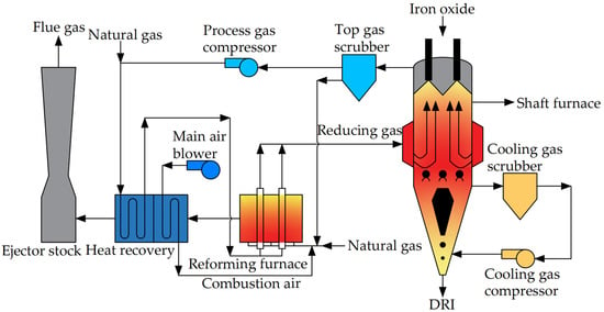
The Midrex direct reduction process, which was developed by the U.S. Midrex company in the 1960s, has consistently been the dominant process for the production of DRI around the globe [46]. The flow of the Midrex direct reduction process is shown in Figure 5, where the main equipment includes a shaft furnace, a reducing gas reforming furnace, a top gas purification device, a top gas waste heat recovery device, and a cooling gas purification device.
Natural gas is used as the main raw material in the Midrex direct reduction process. Following purification, a portion of the top gas is utilized as fuel for the reforming furnace, while the remainder undergoes pressurization. It is then mixed with natural gas and preheated via a heat exchanger before being introduced into the reforming furnace. In the reforming furnace, it undergoes a catalytic cracking reaction to generate high-temperature reducing gas with H2 + CO > 90% and a temperature of about 850–930 °C [47]. Subsequently, the high-temperature reducing gas passes into the middle of the shaft furnace to reduce the iron ore in the furnace. The shaft furnace is divided into a preheating section, reducing section, and cooling section from top to bottom, and there is no obvious boundary between the preheating section and the reducing section. After the iron ore enters the shaft furnace, it is first preheated in the preheating section, and then undergoes a reduction reaction in the reducing section to generate DRI with a metallization rate of about 92%. Finally, the DRI passes the cooling section and is discharged from the furnace. The cooling gas that is discharged can be recycled after undergoing washing and pressurization processes.
3.2.2. Midrex-H2® Process
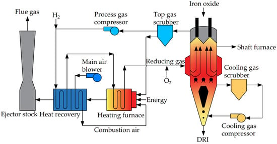
The reducing gas in the Midrex-H2® process is pure H2, and the process flow is shown in Figure 6. Since H2 is introduced externally, no reforming device is needed compared to the Midrex process. In the reducing gas heating furnace, H2 is heated to the desired temperature of the process and then introduced into the furnace to reduce iron ore. Additionally, O2 and H2 can be introduced at the inlet of the reducing gas for the generation of an exothermic oxidizing reaction, thereby increasing the temperature and exothermic oxidizing reaction at the reducing section. According to calculations, the Midrex-H2® process consumes approximately 550 m3 (standard) of H2 to produce one ton of DRI [48], which can reduce carbon emissions by 80% compared to the BF process [47]. Nonetheless, due to the current high production cost of H2, the actual application of the DRI production process with pure H2 needs to be further explored.
3.2.3. HYL-III/Energiron Process
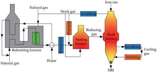
The HYL-III process, also known as the Energiron process, is a shaft furnace mobile bed process developed by the Mexican Hylsa company based on the HYL-I and HYL-II processes, and can achieve continuous production of DRI while reducing energy consumption. The process flow is shown in Figure 7.
In the HYL-III process, the flows can be broadly categorized into two zones: the gas production zone and the reduction zone. In the gas production zone, water vapor serves as the cracking agent and undergoes catalytic cracking reactions with natural gas within the reforming furnace to produce H2 and CO reducing gas. The reducing gas discharged from the reforming furnace initially traverses a heat transfer device to produce water vapor. Subsequently, it proceeds to a cooler where excess water vapor is condensed. Finally, the gas is mixed with a portion of washed top gas before being heated to temperatures ranging from 900 to 960 °C in the reducing gas heating furnace. The main equipment in the reduction zone is the shaft furnace. The high-temperature reducing gas discharged from the reducing gas heating furnace will pass the middle part of the shaft furnace and enter the reduction section to react with the iron ore inside. After reaction, it is discharged from the top of the furnace. Following washing, a portion of the reducing gas is heated in the heating furnace and recycled, while another portion is mixed with natural gas to act as fuel for the reforming furnace. The remaining portion is utilized as fuel for the heating furnace. The cooling section of the HYL-III process is similar to that of the Midrex process. The temperature of the DRI is lowered to about 50 °C in the cooling section and then discharged into the shaft furnace [44].
3.2.4. HYL-ZR Process
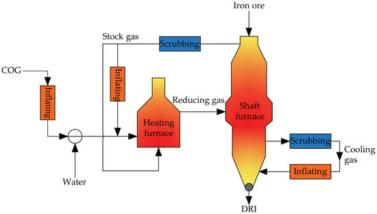
The HYL-ZR process is a CH4 zero reforming process developed on the basis of the HYL-III process. The process flow is shown in Figure 8. Compared with the HYL-III process, the reforming of reducing gas is omitted, and instead, coke oven gas and stock gas are directly employed as the reducing gas. Following heating to the desired temperature in the heating furnace, the reducing gas is directed into the middle section of the shaft furnace to reduce the iron ore. This approach offers a fresh perspective for advancing the H-DRI process in regions or countries limited by natural gas resources. However, owing to the increased content of CH4 in the reducing gas after elimination of gas reforming, attention should be paid to the risk of corrosion of the furnace pipe due to carburization between CH4 and the iron furnace pipe at high temperature.
3.2.5. BL Process
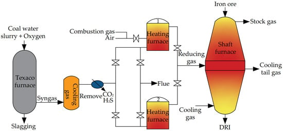
Jointly developed by Baoshan Iron & Steel Co., Ltd. and Lunan Chemicals Co., Ltd., the BL process is an H-DRI process based on coal gasification. The process flow is shown in Figure 9. The BL process represents a novel method for producing DRI through coal gasification. This approach combines Texaco coal water slurry gas production technology with a direct reduction shaft furnace. In the Texaco furnace, a coal water slurry and O2 are used as raw materials, which react in the furnace to generate H2, CO, CO2, and water vapor-based syngas. The discharged syngas is cooled and purified into a reducing gas with H2 + CO > 95%. After being heated to 800–1000 °C in the heating furnace, the reducing gas is fed into the middle part of the shaft furnace to reduce the iron ore. In the BL process, two regenerative heating furnaces are employed to heat the reducing gas. These furnaces operate alternately, with one supplying gas while the other stores heat. This arrangement ensures the continuous operation of the shaft furnace. The process flow of the shaft furnace is similar to that of the Midrex shaft furnace. Despite undergoing only a few semi-industrial tests, the BL process, which utilizes coal gasification for DRI production, provides valuable insights for the development of a DRI production process in regions or countries abundant in coal resources but lacking in gas resources.
3.3. Fluidized Bed Direct Reduction Process
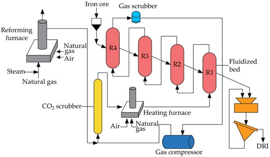
Compared with the shaft furnace direct reduction process, the production scale of the fluidized bed direct reduction process is smaller. However, due to its use of iron ore powder as a raw material, the reduction speed is faster. Jointly developed by Voestalpine and Fior in Venezuela, Finmet is currently one of the most representative fluidized bed direct reduction processes. The process flow is shown in Figure 10. In the Finmet process, the reducing gases are H2 and CO generated by the catalytic cracking reaction of natural gas and water vapor in the reforming furnace. After purification, the reducing gas discharged from the reforming furnace is heated to the desired temperature in the heating furnace before entering the fluidized bed to reduce the iron ore powder. The reducing gas sequentially passes through four parallel fluidized beds to reduce the iron ore powder. Subsequently, it undergoes washing and pressurization for recycling. The discharged DRI powder is then baked and compressed into pieces via a hot press.
3.4. Characteristics Comparison of Typical H-DRI Processes
Although the shaft furnace process is mainly adopted for current production of H-DRI globally, especially the dominating Midrex process, different countries or regions should develop their own H-DRI processes tailored to their national realities and local resource availability. Table 2 summarizes a comparison of the main characteristics of the typical H-DRI processes.
As can be seen from Table 2, HYL-I, HYL-II, HYL-III/Energiron, Finmet, and Midrex processes all use natural gas as the main feedstock to produce reducing gas mainly composed of H2 and CO and are suitable for natural gas-rich regions. The difference is that the HYL-I, HYL-II, HYL-III/Energiron, and Finmet processes use natural gas mixed with water vapor in a reforming furnace to undergo a catalytic cracking reaction to produce reducing gas, which requires the removal of excess water vapor before the reducing gas is placed in the furnace. The Midrex process directly uses natural gas in the reforming furnace for catalytic cracking to produce reducing gas. The Midrex-H2® process uses pure H2 as the reducing gas, and although it can achieve better carbon reduction results, the high cost of H2 has limited its further development at present. The HYL-ZR process directly uses coke oven gas as the reducing gas, which can eliminate the reforming process in the HYL-III/Energiron process, but the corrosion of the furnace tube caused by the carburizing reaction of CH4 in coke oven gas needs to be solved. The BL process uses coal as the main raw material and produces reducing gas through a reforming reaction of coal water slurry and oxygen in a Texaco furnace, which is more suitable for areas with rich coal and less gas sources. In conclusion, the selection of H-DRI should be comprehensively considered from the aspects such as reducing gas source, reducing gas cost, and the complexity of production process.
3.5. Industrial Practice and Development of Typical H-DRI Processes
Over the past few decades, global DRI demand and production have been on an overall upward trend. In 2019, the global DRI production reached 108.1 million tons, of which about 60% of the market share was occupied by the Midrex process [47]. The successful testing of the Midrex process in the United States in 1966 led to the establishment of a factory with a DRI production capacity of 400,000 tons/year in Germany in 1971, marking the inception of the DRI–electric arc furnace continuous casting process. Over time, the single production capacity of Midrex has expanded to 2 million tons/year; the process’s energy consumption stands at 10.2~11 GJ/t DRI [27]. Between 2011 and 2018, the majority of newly built Midrex plants worldwide have a production capacity ranging between 1.5 and 2.5 million tons/year [42]. An example of the large-scale implementation of Midrex process technology is Iran’s Iran-4 modules steel plant, which was commissioned in 2018 with a Midrex process production capacity of 4.85 million tons/year. Notably, the pure-hydrogen Midrex process is still immature and is still in the discussion and test stage, and there is no industrial plant in operation for the time being. Sweden’s HYBRIT project plans to develop a carbon-free ironmaking technology by 2035 by using a pure-hydrogen shaft furnace and electric arc furnace instead of BF [20].
The first HYL tank reactor was built in 1957 with a DRI output of 100,000 tons/year. Subsequent developments expanded the aggregate production capacity of HYL tank reactors to 6 million tons. However, due to the significant drawbacks associated with the HYL tank reactor, such as low production efficiency and high energy consumption (about 17~19 GJ/t DRI) [47], the utilization of this reactor type has gradually diminished. Later on, HYLSA developed the HYL-III shaft furnace moving bed process and built a shaft furnace with a capacity of 500,000 tons/year in 1983 after successful pilot tests. The newly established HYL-III plant witnessed a production capacity approaching that of the Midrex process between 2009 and 2016, encompassing around 2 million tons annually. By 2019, the HYL-III process managed to accumulate a total production capacity of 14.26 million tons, positioning it second only to the Midrex process in terms of output. Additionally, the process’s energy consumption was also reduced to a range of 10~11.3 GJ/t DRI [27]. The HYL-III process, which uses coke oven gas as raw material to produce reducing gas, has also been built in China as a demonstration project. After reforming and purifying, the reducing gas can reach H2 + CO > 90%, and the H2/CO can be adjusted in the range of 1.5~2.0, which promotes the transformation of the iron-making process from carbothermal reduction to hydrogen reduction. As of now, only a handful of factories across the globe employ the HYL-ZR process, limiting the availability of comprehensive data regarding its specific production outcomes.
The BL method is a semi-industrial test of DRI production via a shaft furnace process using a coal-to-gas process. The objective is to ascertain the characteristics of a process that produces more coal and less gas in China. The designed production capacity is 5 tons/day. Over the course of 33 operational days, the process yielded 132 tons of DRI, achieving an average metallization rate of 93.04% with a coal consumption rate of 482 kg/t DRI [47]. However, the method’s potential for further industrial-scale production has been constrained by various factors, including the deficiency of high-grade ore, costly gas production, and environmental protection constraints. Consequently, the achievement of sustained industrial-scale production remains elusive.
The fluidized bed direct reduction process has been under development since the 1960s. A noteworthy achievement in this area is the completion of the Finmet system DRI plant in Venezuela in 2001, with an annual production capacity of 1 million tons. The fluidized bed process uses iron ore powder as raw material and saves energy consumption in the block building process. However, due to the shortcomings of difficult control, low yield, and easy bonding, it has not been popularized.
Generally speaking, due to more practical experience and mature technical level, Midrex and HYL-III shaft furnace processes are still the most mainstream and recommended for industrial application. At present, the H-DRI process is mostly used in countries or regions with low natural gas costs. For countries and regions lacking natural gas, the development of the H-DRI process relies on the development of other low-cost reducing gas sources.
4. Research on Process Optimization of H-DRI
In addition to the research on the basic theories on thermodynamics and dynamics of reduction reactions, the main focus of existing research has been on the optimization of the H-DRI process. This includes enhancing the utilization rate of reducing gas, improving gas heat recovery rates, optimizing material flow within furnaces, enhancing energy utilization efficiency, reducing exergy intensity, and seeking reasonable process parameters. Such efforts have significantly contributed to the ongoing advancement of hydrogen metallurgy. The research on process optimization in several references is summarized in Table 3.
The results show that a reducing gas temperature range between 900 and 1000 °C is recommended for effective control of energy consumption [34,50,53]. It is also crucial to regulate the composition of the reducing gas, particularly the proportion of H2. For optimal energy utilization, the proportion of H2 should be maintained at about 20–40% [34,50]. In addition to the rational control of key process parameters, enhancing the gas injection method, harnessing waste heat, reclaiming unreacted reducing gas, and employing a well-designed reactor structure are all essential measures that can contribute to the production and energy efficiency of the H-DRI process [49,51,52,54,55,56].
For the optimization of the H-DRI process, in addition to the above studies, it is necessary to continue to optimize the production performance of key equipment such as the reducing gas reforming furnace and the heating furnace and reactor and to continue to study the reasonable selection of important process parameters such as reduction temperature, pressure, and reducing proportion under different processes and production conditions. Developing low-cost reducing gas preparation methods are also critical to the promotion of the H-DRI process. In addition, the research on the recovery of waste heat and energy in the whole process is very beneficial to energy saving and efficiency.
5. Industrial Application Projects of H-DRI Process in Recent Years
The H-DRI process has matured significantly after years of development. In recent years, numerous projects involving this process have either been developed, tested, or initiated production [6,16,20,47,57]. These projects not only contribute to carbon emissions reduction but also offer valuable experience in process development. Table 4 provides a summary of several representative H-DRI projects worldwide in recent years.
An observation can be made from these projects that the adoption of a hydrogen metallurgy process to promote carbon reduction in the ISI is a shared global objective for the foreseeable future. Direct reduction using shaft furnaces remains the predominant method for producing DRI. Currently, electrolytic water-generated hydrogen, natural gas-generated hydrogen, coal-generated hydrogen, and byproduct gas-generated hydrogen serve as the primary reducing gases in the H-DRI process. The generation of electricity with renewable energy → generation of hydrogen with electrolytic water may emerge as the primary route for hydrogen production in certain countries or regions in the future. This will largely depend on the cost of generating renewable energy. For countries or regions abundant in coal resources but limited in natural gas, such as China, the combination of hydrogen generation with coal gas, natural gas, and byproduct gas aligns better with domestic conditions.
6. Problems and Challenges of H-DRI Process
For the commercialization of H-DRI processes, a stable source of low-cost H2 is considerably vital. At present, the preparation methods of H2 include coal gasification, coke oven gas reforming, methane water vapor reforming, water electrolysis, and nuclear hydrogen production [58,59,60,61]. Among such methods, the mature method for mass hydrogen production still relies on fossil fuels as raw materials, which deviates from low-carbon development goals. At present, the cost of hydrogen production via electrolytic water remains prohibitively high, rendering it unsuitable for mass industrial applications. Nuclear hydrogen production is generally in the experimental stage, and commercialization is not expected until 2030 [26]. Safe and efficient storage and transportation technology is also another significant factor that needs to be addressed in the current utilization of hydrogen energy [62,63]. The broader development of the H-DRI process will only be possible when stable and abundant resources of affordable hydrogen become available.
High-quality high-grade iron ore is another necessary raw material for the H-DRI process. In order to prevent an adverse effect on production efficiency and product quality due to agglomeration and adhesion of iron ore particles during the reduction, high-grade iron ore should be used in the H-DRI process [9]. However, the continuous mining of iron ore has led to a shortage of high-grade iron ore to some extent. To address this challenge, efforts can focus on two aspects: first, enhancing the mineral processing of iron concentrate to maximize its yield and quality, and second, developing H-DRI processes tailored for the use of low-grade iron ore.
Reduction of iron ore with H2 involves a strong endothermic reaction. If the proportion of H2 in the reduction gas is too high, it can lead to heightened energy consumption and a reduced utilization rate of the reduction gas during the reduction process. While this may result in greater reduction in carbon emissions, it also poses challenges related to energy efficiency and gas utilization [64]. Additionally, the DRI produced via pure-hydrogen reduction has the characteristics of no carburization, high reactivity, high melting point, easy oxidation, and is difficult to store and transport. The high melting point will increase the power consumption of subsequent electric arc furnace refining. In contrast, the reduction of iron ore with CO involves an exothermic reaction, which can replenish the heat inside the reaction vessel. The mixing of CO can also supplement the carbon content in DRI. Therefore, it is necessary to continue in-depth research on the balance between carbon reduction and hydrocarbon collaboration in the H-DRI process.
The reduction reaction between a reducing gas and iron ore is influenced by various factors, including the composition, temperature, and pressure of the reducing gas, reactor design, temperature and pressure control within the reactor, residence time of the iron ore, etc. [47,49,56,65,66,67]. To fully exploit the advantages of the H2 reduction reaction in terms of speed and mass transfer at high temperatures, it is necessary to make use of the production experience gained from existing industrial H-DRI processes and optimize and improve various process parameters, key process equipment, and the overall process flow by combining theoretical calculations and practical considerations.
Safety is a crucial aspect of the H-DRI process due to the active chemical properties and flammable and explosive characteristics of H2 [47]. Therefore, it is imperative to ensure high leak resistance of reactors and pipelines. The low density of H2 makes it susceptible to escaping to the top of the reactor, thus resulting in insufficient residence time in the reduction section. As a consequence, the complete reduction task of iron ore cannot be achieved effectively. Furthermore, attention needs to be given to the sealing safety of the reducing gas heating furnace and reactor equipment, as well as the potential hydrogen reduction damage to refractory materials during actual production. In addition, hydrogen embrittlement may occur in furnace tubes, reducing gas transport pipes and reactors [68]. These challenges pose obstacles to the industrial application of the H-DRI process, necessitating further testing and improvement.
7. Conclusions
- The ISI is an industry with high carbon emissions, largely due to the extensive use of coal in the ironmaking process. Hydrogen metallurgy presents a promising solution to reduce carbon emissions at the source, facilitating green and low-carbon development within the ISI. Among hydrogen metallurgy processes, the H-DRI process stands out due to its significant carbon emission reduction and mature process, making it one of the most promising avenues for development. In addition, the development of the H-DRI process is also of great significance for promoting the ISI’s short process technology and energy structure optimization;
- The H-DRI process has been used in some industrial applications around the world over the past decades, but it is still in the development stage overall. The tank HYL, Midrex, Midrex-H2®, HYL-III/Energiron, HYL-ZR, BL, and Finmet processes are several typical H-DRI processes. Based on the comparison of characteristics of these different typical H-DRI processes, combined with production capacity, energy consumption, and process maturity, the Midrex and HYL-III/Energiron shaft furnace processes are currently recommended mainstream choices. Due to the high cost of pure-hydrogen reduction, it is more practical to use hydrogen-rich gas as the reducing gas in the H-DRI process. The main raw materials of reducing gas are natural gas, byproduct gas, coal gas, and external hydrogen. Different countries or regions should choose their own reducing gas raw material sources according to the characteristics of local resources;
- For H-DRI process optimization, existing studies have shown that in order to give full play to the advantage of fast hydrogen reduction rate, the temperature of the reduction reaction should be controlled above 820 °C. From the point of view of reducing energy consumption, the temperature of the reducing gas should be controlled between 900 °C and 1000 °C, and the range of H2 in the reducing gas should be controlled between 20% and 40%. Preheating of ore, recovery of top gas, and adoption of double-gas injection are all measures that contribute to enhancing the utilization rate of the reducing gas, reducing energy consumption, and improving production efficiency. In addition to the existing research results, it is necessary to continue to improve of the production performance of key equipment such as the reducing gas reforming furnace and the heating furnace and reactor, develop low-cost reducing gas preparation methods, strengthen the recovery of waste heat and energy in the overall process, and improve the overall utilization rate of energy and reducing gas;
- In the long run, if low-cost renewable energy power generation can be achieved, the generation of power with renewable energy → production of hydrogen with electrolytic water may become a mainstream hydrogen production method. In the present and future period of time, it is proposed to reduce the cost of reducing gas preparation by using byproduct gas, natural gas, and other hydrogen-rich gases, combined with the electrolysis of water to produce the reducing gas required for the H-DRI process;
- To secure stable sources of inexpensive H2, advancements in hydrogen production and storage technologies are imperative. Addressing the shortage of high-grade iron ore can be achieved through enhancements in the mineral processing of iron concentrate and the development of H-DRI processes utilizing low-grade iron ore. To diminish energy consumption and enhance the utilization rate of reducing gas, ongoing in-depth research is necessary to strike a balance between carbon emission reduction and hydrocarbon collaboration in the H-DRI process. Moreover, from the perspective of H-DRI process safety production, the corrosion and damage caused by H2 to reactors and transportation pipelines under different conditions require more testing.
Author Contributions
Conceptualization, Y.J., Z.C. and W.Z.; methodology, Y.J. and Z.C.; software, Y.J., S.Y. and Y.C.; validation, Y.J., Z.C., S.Y. and Y.C.; formal analysis, Y.J., Z.C., Y.L. and T.J.; investigation, Y.J. and Z.C.; resources, Y.J. and Z.C.; data curation, Y.J., Z.C. and X.L.; writing—original draft preparation, Y.J.; writing—review and editing, Y.J., Z.C., S.Y. and Y.C.; visualization, Y.J. and Z.C.; supervision, W.Z.; project administration, W.Z.; funding acquisition, W.Z. All authors have read and agreed to the published version of the manuscript.
Funding
This study was funded by the National Key Research and Development Program of China (Grant No. 2017YFA0700300).
Data Availability Statement
No new data were created or analyzed in this study. Data sharing is not applicable to this article.
Conflicts of Interest
The authors declare no conflicts of interest.
References
- Kim, J.; Sovacool, B.K.; Bazilian, M.; Griffiths, S.; Lee, J.; Yang, M.; Lee, J. Decarbonizing the iron and steel industry: A systematic review of sociotechnical systems, technological innovations, and policy options. Energy Res. Social Sci. 2022, 89, 102565. [Google Scholar] [CrossRef]
- Meng, F.; Rong, G.; Zhao, R.; Chen, B.; Xu, X.; Qiu, H.; Cao, X.; Zhao, L. Incorporating biochar into fuels system of iron and steel industry: Carbon emission reduction potential and economic analysis. Appl. Energy 2024, 356, 122377. [Google Scholar] [CrossRef]
- Sun, W.; Wang, Q.; Zhou, Y.; Wu, J. Material and energy flows of the iron and steel industry: Status quo, challenges and perspectives. Appl. Energy 2020, 268, 114946. [Google Scholar] [CrossRef]
- Ledari, M.B.; Khajehpour, H.; Akbarnavasi, H.; Edalati, S. Greening steel industry by hydrogen: Lessons learned for the developing world. Int. J. Hydrogen Energy 2023, 48, 36623–36649. [Google Scholar] [CrossRef]
- Sun, C.; Wang, J.; Zhou, M.; Hong, L.; Ai, L.; Wen, L. Process Path for Reducing Carbon Emissions from Steel Industry-Combined Electrification and Hydrogen Reduction. Processes 2024, 12, 108. [Google Scholar] [CrossRef]
- Shahabuddin, M.; Brooks, G.; Rhamdhani, M.A. Decarbonisation and hydrogen integration of steel industries: Recent development, challenges and technoeconomic analysis. J. Clean. Prod. 2023, 395, 136391. [Google Scholar] [CrossRef]
- Yuan, Y.; Na, H.; Du, T.; Qiu, Z.; Sun, J.; Yan, T.; Che, Z. Multi-objective optimization and analysis of material and energy flows in a typical steel plant. Energy 2023, 263, 125874. [Google Scholar] [CrossRef]
- Kang, Z.; Liao, Q.; Zhang, Z.; Zhang, Y. Carbon neutrality orientates the reform of the steel industry. Nat. Mater. 2022, 21, 1094–1098. [Google Scholar] [CrossRef]
- Sun, M.; Pang, K.; Barati, M.; Meng, X. Hydrogen-Based Reduction Technologies in Low-Carbon Sustainable Ironmaking and Steelmaking: A Review. J. Sustain. Metall. 2024, 10, 10–25. [Google Scholar] [CrossRef]
- Zhang, Y.; Zhou, Y.; Li, Z. Low Coke Rate Ironmaking in Blast Furnace with Hot Gas Injection. J. Iron Steel Res. Int. 2009, 16, 800–803. [Google Scholar]
- Andrade, C.; Desport, L.; Selosse, S. Net-negative emission opportunities for the iron and steel industry on a global scale. Appl. Energy 2024, 358, 122566. [Google Scholar] [CrossRef]
- Conejo, A.N.; Birat, J.P.; Dutta, A. A review of the current environmental challenges of the steel industry and its value chain. J. Environ. Manag. 2020, 259, 109782. [Google Scholar] [CrossRef] [PubMed]
- Wan, F.; Li, J.; Han, Y.; Yao, X. Research of the impact of hydrogen metallurgy technology on the reduction of the Chinese Steel Industry’s carbon dioxide emissions. Sustainability 2024, 16, 1814. [Google Scholar] [CrossRef]
- Özguen, O.; Lu, X.; Ma, Y.; Raabe, D. How much hydrogen is in green steel? Npj Mater. Degrad. 2023, 7, 78. [Google Scholar] [CrossRef]
- Gielen, D.; Saygin, D.; Taibi, E.; Birat, J.P. Renewables-based decarbonization and relocation of iron and steel making: A case study. J. Ind. Ecol. 2020, 24, 1113–1125. [Google Scholar] [CrossRef]
- Tang, J.; Chu, M.; Li, F.; Feng, C.; Liu, Z.; Zhou, Y. Development and progress on hydrogen metallurgy. Int. J. Min. Met. Mater. 2020, 27, 713–723. [Google Scholar] [CrossRef]
- Chang, Y.; Wan, F.; Yao, X.; Wang, J.; Han, Y.; Li, H. Influence of hydrogen production on the CO2 emissions reduction of hydrogen metallurgy transformation in iron and steel industry. Energy Rep. 2023, 9, 3057–3071. [Google Scholar] [CrossRef]
- Chen, Y.; Zuo, H. Review of hydrogen-rich ironmaking technology in blast furnace. Ironmak. Steelmak. 2021, 48, 749–768. [Google Scholar] [CrossRef]
- Guo, H. Physicochemical principles of hydrogen metallurgy in blast furnace. J. Iron. Steel Res. Int. 2024, 31, 46–63. [Google Scholar] [CrossRef]
- Zhang, X.; Jiao, K.; Zhang, J.; Guo, Z. A review on low carbon emissions projects of steel industry in the World. J. Clean. Prod. 2021, 306, 127259. [Google Scholar] [CrossRef]
- Bhaskar, A.; Assadi, M.; Somehsaraei, H.N. Decarbonization of the Iron and Steel Industry with Direct Reduction of Iron Ore with Green Hydrogen. Energies 2020, 13, 758. [Google Scholar] [CrossRef]
- Souza, I.R.; Ma, Y.; Kulse, M.; Ponge, D.; Gault, B.; Springer, H.; Raabe, D. Sustainable steel through hydrogen plasma reduction of iron ore: Process, kinetics, microstructure, chemistry. Acta Mater. 2021, 213, 116971. [Google Scholar]
- Yilmaz, C.; Wendelstorf, J.; Turek, T. Modeling and simulation of hydrogen injection into a blast furnace to reduce carbon dioxide emissions. J. Clean. Prod. 2017, 154, 488–501. [Google Scholar] [CrossRef]
- Lu, L.; Wang, F.; Wang, H.; Qiu, J.; Ping, X. Research status on thermodynamics and kinetics of carbon and hydrogen reduction of molten iron oxides. J. Iron Steel Res. 2024, 36, 150–162. [Google Scholar]
- Li, F.; Chu, M.; Tang, J.; Liu, Z.; Zhao, Z.; Liu, P.; Yan, R. Quantifying the energy saving potential and environmental benefit of hydrogen-based steelmaking process: Status and future prospect. Appl. Therm. Eng. 2022, 211, 118489. [Google Scholar] [CrossRef]
- Wang, R.; Zhao, Y.; Babich, A.; Senk, D.; Fan, X. Hydrogen direct reduction (H-DR) in steel industry-An overview of challenges and opportunities. J. Cleaner Prod. 2021, 329, 129797. [Google Scholar] [CrossRef]
- Liu, W.; Zuo, H.; Wang, J.; Xue, Q.; Ren, B.; Yang, F. The production and application of hydrogen in steel industry. Int. J. Hydrogen Energy 2021, 46, 10548–10569. [Google Scholar] [CrossRef]
- Spreitzer, D.; Schenk, J. Reduction of iron oxides with hydrogen—A review. Steel Res. Int. 2019, 90, 1900108. [Google Scholar] [CrossRef]
- Cavaliere, P. Hydrogen Assisted Direct Reduction of Iron Oxides, 1st ed.; Springer: Cham, Switzerland, 2022; pp. 47–74. [Google Scholar]
- Fradet, Q.; Kurnatowska, Q.; Riedel, U. Thermochemical reduction of iron oxide powders with hydrogen: Review of selected thermal analysis studies. Thermochim. Acta 2023, 726, 179552. [Google Scholar] [CrossRef]
- Anameric, B.; Kawatra, S.K. Properties and features of direct reduced iron. Miner. Process. Extr. Metall. Rev. 2007, 28, 59–116. [Google Scholar] [CrossRef]
- Béchara, R.; Hamadeh, H.; Mirgaux, O.; Patisson, F. Optimization of the iron ore direct reduction process through multiscale process modeling. Materials 2018, 11, 1094. [Google Scholar] [CrossRef] [PubMed]
- Anameric, B.; Kawatra, S.K. Direct iron smelting reduction processes. Miner. Process. Extr. Metall. Rev. 2009, 30, 1–51. [Google Scholar] [CrossRef]
- Chen, Z.; Dang, J.; Hu, X.; Yan, H. Reduction kinetics of hematite powder in hydrogen atmosphere at moderate temperatures. Metals 2018, 8, 751. [Google Scholar] [CrossRef]
- Elzohiery, M.; Sohn, H.Y.; Mohassab, Y. Kinetics of hydrogen reduction of magnetite concentrate particles in solid state relevant to flash ironmaking. Steel Res. Int. 2017, 88, 290–303. [Google Scholar] [CrossRef]
- Jozwiak, W.K.; Kaczmarek, E.; Maniecki, T.P.; Ignaczak, W.; Maniukiewicz, W. Reduction behavior of iron oxides in hydrogen and carbon monoxide atmospheres. Appl. Catal. A Gen. 2007, 326, 17–27. [Google Scholar] [CrossRef]
- Ma, Y.; Souza Filho, I.R.; Zhang, X.; Nandy, S.; Barriobero-Vila, P.; Requena, G.; Vogel, D.; Rohwerder, M.; Ponge, D.; Springer, H.; et al. Hydrogen-based direct reduction of iron oxide at 700 °C: Heterogeneity at pellet and microstructure scales. Int. J. Miner. Metall. Mater. 2022, 29, 1901–1907. [Google Scholar] [CrossRef]
- Cavaliere, P.; Perrone, A.; Dijon, L.; Laska, A.; Koszelow, D. Direct reduction of pellets through hydrogen: Experimental and model behaviour. Int. J. Hydrogen Energy 2024, 49, 1444–1460. [Google Scholar] [CrossRef]
- Zakeri, A.; Coley, K.S.; Tafaghodi, L. Hydrogen-based direct reduction of iron oxides: A review on the influence of impurities. Sustainability 2023, 15, 13047. [Google Scholar] [CrossRef]
- Weiss, B.; Sturn, J.; Winter, F.; Schenk, J.L. Empirical reduction diagrams for reduction of iron ores with H2 and CO gas mixtures considering non-stoichiometries of oxide phases. Ironmak. Steelmak. 2009, 36, 212–216. [Google Scholar] [CrossRef]
- Liu, Y. Physical Chemistry, 1st ed.; Southwest Jiaotong University Press: Chengdu, China, 2020; pp. 169–170. [Google Scholar]
- Zhang, J.; Li, K.; Liu, Z.; Yang, T. Primary Exploration of Hydrogen Metallurgy, 1st ed.; Springer: Singapore, 2024; pp. 117–171. [Google Scholar]
- Lin, X.; Ni, B.; Shangguan, F. Numerical simulation of the hydrogen-based directly reduced iron melting process. Processes 2024, 12, 537. [Google Scholar] [CrossRef]
- Zervas, T.; McMullan, J.T.; Williams, B.C. Gas-based direct reduction processes for iron and steel production. Int. J. Energy Res. 1996, 20, 157–185. [Google Scholar] [CrossRef]
- Fang, J. Non-Blast Furnace Ironmaking Technology and Theory, 2nd ed.; Metallurgical Industry Press: Beijing, China, 2010; pp. 116–147. [Google Scholar]
- Trinca, A.; Patrizi, D.; Verdone, N.; Bassano, C.; Vilardi, G. Toward green steel: Modeling and environmental economic analysis of iron direct reduction with different reducing gases. J. Clean. Prod. 2023, 427, 139081. [Google Scholar] [CrossRef]
- Wang, X.; Wang, T.; Chu, M. Progress and Key Problems of Hydrogen Metallurgy, 1st ed.; Chemical Industry Press: Beijing, China, 2023; pp. 46–70+88–112. [Google Scholar]
- Cavaliere, P. Clean Ironmaking and Steelmaking Process, 1st ed.; Springer: Cham, Switzerland, 2019; p. 460. [Google Scholar]
- Ghadi, A.Z.; Valipour, M.S.; Biglari, M. CFD simulation of two-phase gas-particle flow in the Midrex shaft furnace: The effect of twin gas injection system on the performance of the reactor. Int. J. Hydrogen Energy 2017, 42, 103–118. [Google Scholar] [CrossRef]
- Qiu, Z.; Du, T.; Yue, Q.; Na, H.; Sun, J.; Yuan, Y.; Che, Z.; Wang, Y.; Li, Y. A multi-parameters evaluation on exergy for hydrogen metallurgy. Energy 2023, 281, 128279. [Google Scholar] [CrossRef]
- Xu, K.; Bai, M. DEM simulation of particle descending velocity distribution in the reduction shaft furnace. Metall. Res. Technol. 2016, 113, 603. [Google Scholar] [CrossRef][Green Version]
- Li, F.; Chu, M.; Tang, J.; Liu, Z.; Zhou, Y.; Wang, J. Exergy analysis of hydrogen-reduction based steel production with coal gasification-shaft furnace-electric furnace process. Int. J. Hydrogen Energy 2021, 46, 12771–12783. [Google Scholar] [CrossRef]
- Liu, Z.; Lu, S.; Wang, Y.; Zhang, J.; Cheng, Q.; Ma, Y. Study on optimization of reduction temperature of hydrogen-based shaft furnaced numerical simulation and multi-criteria evaluation. Int. J. Hydrogen Energy 2023, 48, 16132–16142. [Google Scholar] [CrossRef]
- Li, Z.; Qi, Z.; Zhang, L.; Guo, M.; Liang, D.; Dong, Q. Numerical simulation of H2-intensive shaft furnace direct reduction process. J. Cleaner Prod. 2023, 409, 137059. [Google Scholar] [CrossRef]
- Qiu, Z.; Yue, Q.; Yan, T.; Wang, Q.; Sun, J.; Yuan, Y.; Che, Z.; Wang, Y.; Du, T. Gas utilization optimization and exergy analysis of hydrogen metallurgical shaft furnace. Energy 2023, 263, 125847. [Google Scholar] [CrossRef]
- Shao, L.; Zhang, X.; Zhao, C.; Qu, Y.; Saxén, H.; Zou, Z. Computational analysis of hydrogen reduction of iron oxide pellets in a shaft furnace process. Renew. Energ. 2021, 179, 1537–1547. [Google Scholar] [CrossRef]
- Quader, M.A.; Ahmed, S.; Dawal, S.Z.; Nukman, Y. Present needs, recent progress and future trends of energy-efficient Ultra-Low Carbon Dioxide (CO2) Steelmaking (ULCOS) program. Renew. Sustain. Energy Rev. 2016, 55, 537–549. [Google Scholar] [CrossRef]
- Acar, C.; Dincer, I. Review and evaluation of hydrogen production options for better environment. J. Clean. Prod. 2019, 218, 835–849. [Google Scholar] [CrossRef]
- Baykara, S.Z. Hydrogen: A brief overview on its sources, production and environmental impact. Int. J. Hydrogen Energy 2018, 43, 10605–10614. [Google Scholar] [CrossRef]
- Ishaq, H.; Dincer, I. Comparative assessment of renewable energy-based hydrogen production methods. Renew. Sustain. Energy Rev. 2021, 135, 110192. [Google Scholar] [CrossRef]
- Sharma, S.; Ghoshal, S.K. Hydrogen the future transportation fuel: From production to applications. Renew. Sustain. Energy Rev. 2015, 43, 1151–1158. [Google Scholar] [CrossRef]
- Abdalla, A.M.; Hossain, S.; Nisfindy, O.B.; Azad, A.T.; Dawood, M.; Azad, A.K. Hydrogen production, storage, transportation and key challenges with applications: A review. Energy Convers. Manag. 2018, 165, 602–627. [Google Scholar] [CrossRef]
- Andersson, J.; Grönkvist, S. A comparison of two hydrogen storages in a fossil-free direct reduced iron process. Int. J. Hydrogen Energy 2021, 46, 28657–28674. [Google Scholar] [CrossRef]
- Chai, X.; Yue, Q.; Zhang, Y.; Wang, Q. Analysis of energy consumption and its influencing factors in hydrogen metallurgy process. Steel Res. Int. 2022, 93, 2100730. [Google Scholar] [CrossRef]
- Hessling, O.; Fogelström, J.B.; Kojola, N.; Du, S. The effect of the endothermic reaction nature on the iron ore pellet reduction using hydrogen. Metall. Mater. Trans. B 2022, 53, 1258–1268. [Google Scholar] [CrossRef]
- Liu, D.; Wang, X.; Zhang, J.; Liu, Z.; Jiao, K.; Liu, X.; Wang, R. Study on the controlling steps and reduction kinetics of iron oxide briquettes with CO-H2 mixtures. Metall. Res. Technol. 2017, 114, 611. [Google Scholar] [CrossRef]
- Hessels, C.J.M.; Homan, T.A.M.; Deen, N.G.; Tang, Y. Reduction kinetics of combusted iron powder using hydrogen. Powder Technol. 2022, 407, 117540. [Google Scholar] [CrossRef]
- Sandeep, K.D.; Manish, V. Hydrogen embrittlement in different materials: A review. Int. J. Hydrogen Energy 2018, 43, 21603–21616. [Google Scholar]
Disclaimer/Publisher’s Note: The statements, opinions and data contained in all publications are solely those of the individual author(s) and contributor(s) and not of MDPI and/or the editor(s). MDPI and/or the editor(s) disclaim responsibility for any injury to people or property resulting from any ideas, methods, instructions or products referred to in the content. |
© 2024 by the authors. Licensee MDPI, Basel, Switzerland. This article is an open access article distributed under the terms and conditions of the Creative Commons Attribution (CC BY) license (https://creativecommons.org/licenses/by/4.0/).
