Article

The Three-Dimensional Heterogeneous Simulation Study of CO2 Flooding in Low-Permeability Reservoirs

School of Petroleum Engineering, Yangtze University, Wuhan 430102, China
*
Author to whom correspondence should be addressed.
Processes 2024, 12(9), 1843; https://doi.org/10.3390/pr12091843
Submission received: 7 June 2024 / Revised: 11 August 2024 / Accepted: 23 August 2024 / Published: 29 August 2024

Abstract

:
CO2 flooding can significantly enhance oil recovery. However, the research on the distribution of remaining oil after CO2-oil and the method of further enhancing oil recovery still needs to be strengthened. Traditional studies on the mechanisms of CO2 flooding to enhance oil recovery mainly focus on core displacement experiments. In order to better simulate the actual field conditions, we conducted a three-dimensional heterogeneous physical simulation experiment. Compared to conventional core displacement experiments, three-dimensional heterogeneous physical model displacement experiments align more closely with actual conditions at the oilfield site. This study establishes a large-scale indoor three-dimensional high-temperature high-pressure displacement physical model and employs three different oil displacement methods: CO2–Water alternating flooding, CO2–Water alternating combined with foam flooding, and CO2–Water alternating combined with imbibition agent flooding. The study investigates the distribution of residual oil and recovery in heterogeneous reservoirs under different injection and production methods. We proposed three experimental schemes to see which one would have better effects in the oilfield. Experimental results show that CO2–Water alternating flooding combined with different chemical flooding agents improves oil recovery. The CO2–Water alternating combined with an imbibition enhancer flooding method achieves the best results, with recovery increased by 16.3% and 1.7% compared to CO2–Water alternating flooding and CO2–Water alternating combined with foam flooding, respectively. The imbibition agent significantly improves wettability and spontaneous imbibition by reducing interfacial tension and resolving the issue of CO2 failing to enter small pores under low differential pressure conditions, thereby maximizing recovery and displacement efficiency.

1. Introduction

In recent years, most oilfields in China have entered the mid-to-late development stage, characterized by rapid production decline and poor development outcomes. Low-permeability reservoirs hold great potential in the field of unconventional oil and gas. To enhance the supply capacity of Chinese oil and gas resources, achieving the goals of stabilizing oil production and increasing gas production through the vigorous development of low-permeability reservoirs is imperative [1,2,3,4,5,6,7,8,9]. CO2, as a widely used and efficient oil displacement agent, can effectively enhance oil and gas production in low-permeability reservoirs by reducing the oil–water interfacial tension, decreasing crude oil viscosity, causing crude oil volume expansion, improving the mobility ratio, acidizing and unclogging, and extracting light components [10,11,12,13]. This makes CO2 flooding one of the most promising methods for enhanced oil recovery in tertiary oil recovery. Domestically and internationally, research has focused on CO2–Water alternating flooding. Researchers such as Li Xiangliang and Du Chaofeng [14,15,16,17] used actual cores and reservoir fluids from Shengli Oilfield and Changqing Oilfield to study the effects of injection timing, injection method, injection volume, and permeability on displacement efficiency, through indoor CO2–Water alternating flooding core displacement experiments [18,19,20].
Foam has been used in field experiments abroad since the 1960s and is now widely applied in various areas of the petroleum industry, including drilling, enhanced oil recovery, and acid fracturing, due to its strong functionality and diverse systems. Studies have shown [21,22,23] that foam can act as a CO2 gas channeling inhibitor, delaying gas breakthrough, increasing the displacement pressure differential, and expanding the sweep range. Foam can reverse the flow rate distribution in formations with permeability contrasts and expand the sweep volume, significantly improving sweep efficiency, making it well suited for low-permeability heterogeneous reservoirs. The mechanism of gas–water foam flooding involves the foam liquid entering the porous medium, forming liquid films in the pores, and subsequently generating separate foams at the pore throats. The formation of numerous foams not only increases the apparent viscosity but also significantly reduces the gas-phase permeability. Foam fluids exhibit unique flow characteristics in porous media, with the liquid and gas phases moving separately. As the displacement progresses, foam continues to be generated, and the displacement pressure gradually increases. When the pressure increases and exceeds the threshold pressure of the seepage disadvantaged channels, the foam begins to divert into these channels. In the seepage disadvantaged channels, the pore throat radius is relatively small, resulting in a correspondingly lower apparent viscosity of the foam. Moreover, these channels typically have a higher oil saturation, making the foam fluid unstable and experiencing relatively low flow resistance within them. Consequently, foam fluid becomes unstable in weak flow channels, and flow resistance decreases. Additionally, the surfactants carried in the foam liquid films significantly reduce the oil–water interfacial tension in the porous medium. Therefore, gas–water alternating combined with foam flooding can reduce the oil–water mobility ratio and enhance the sweep efficiency, while significantly reducing the oil–water interfacial tension and improving displacement efficiency.
Researchers have been studying the impact of imbibition enhancers on oil recovery since the 19th century. Most scholars currently believe that imbibition enhancers affect the imbibition oil recovery process in two ways [24,25]. Firstly, by reducing interfacial tension, which is generally believed to aid in enhancing imbibition recovery as it improves the displacement efficiency of the enhancer and expands the sweep volume, converting some trapped oil into movable oil and strengthening imbibition. Secondly, by altering wettability, with more hydrophilic cores exhibiting higher imbibition recovery. The mechanism of CO2–Water combined with imbibition enhancer flooding involves injecting the gas and the enhancer to change the physical state of the reservoir, thereby promoting oil diffusion and movement. The imbibition enhancer has strong adsorption and electrostatic effects, allowing it to adhere to the oil layer surface, enhancing permeability and infiltration capacity.
CO2 flooding has achieved good results in field applications across various reservoirs globally, but issues such as low sweep efficiency and gas channeling persist in continuous CO2 flooding modes. There are significant differences in development outcomes across regions with varying permeability, with low-permeability areas showing limited oil increment potential after gas breakthrough [26] Therefore, adjusting CO2 flooding methods is an effective means to control gas channeling and expand the sweep efficiency, further enhancing recovery. This study builds on the research of CO2–Water alternating flooding by adding two different displacement methods: CO2–Water alternating combined with foam flooding and CO2–Water alternating combined with imbibition enhancer composite flooding. An indoor three-dimensional high-temperature high-pressure displacement model was established to simulate displacement experiments [27,28,29,30,31]. By measuring the resistivity at various positions within the core and observing saturation changes, a three-dimensional core saturation distribution map was obtained. Additionally, this study analyzed the changes in the displacement efficiency and sweep coefficient during CO2 flooding and the distribution characteristics of residual oil in heterogeneous sandstone reservoirs [32,33,34,35,36,37]. By comparing the development characteristics of the CO2–Water alternating flooding, CO2–Water alternating combined with foam flooding, and CO2–Water alternating combined with imbibition enhancer composite flooding, this study evaluated ways to further improve recovery, the adaptability of CO2 for enhanced oil recovery, and geological sequestration under different reservoir permeability conditions [38,39,40,41,42,43]. This has significant theoretical and practical implications for enhancing recovery in low-permeability reservoirs.

2. Experimental Materials and Equipment

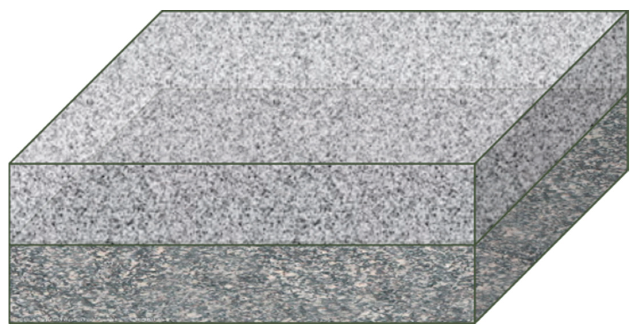
2.1. Experimental Core

The artificial square core has dimensions of 30 × 30 × 10 cm and is divided into two layers, each with a thickness of 5 cm, as shown in Figure 1. The upper layer is a high-permeability layer with a permeability of 75 mD and a porosity of 19.1%. The lower layer is a low-permeability layer with a permeability of 15 mD and a porosity of 17.1%. The core is primarily composed of quartz (60–75%), feldspar (20–23%), and rock fragments (6–9%), with kaolinite and chlorite as the matrix components (about 10%).

2.2. Experimental Fluids

The experimental oil is simulated oil formulated from formation crude oil, and white oil is used to simulate the confining pressure environment under experimental conditions. The experimental gas is 99.9% high-purity carbon dioxide. The experimental water is formation water with a total salinity of 23,947.3 mg/L. The ionic composition of the formation water is shown in Table 1.

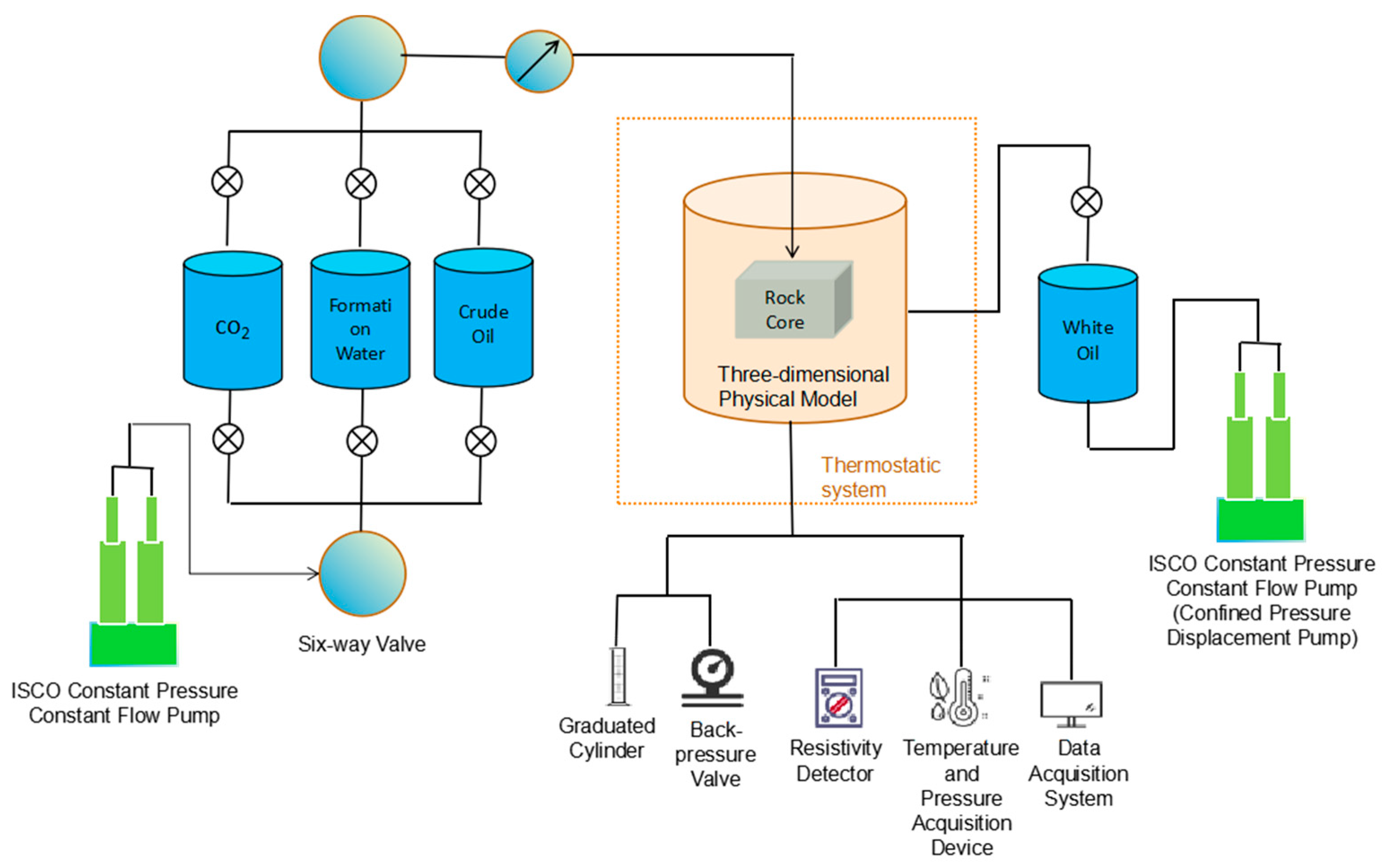
2.3. Experimental Equipment and Materials

The equipment and materials used in the experiment include a resistivity detector, displacement pump, constant pressure and constant rate pump, hand pump, back-pressure valve, gas-liquid separation device, computer data acquisition system, pressure sensors, sensor display, standard digital pressure gauge, probes, foam agent FC-2 (betaine-type surfactant) [44], imbibition agent SXJ-2 (cationic fluorocarbon surfactant), mainframe, core slabs, rubber sleeves, soldering iron, several pipelines, graduated measuring cylinder, and beaker as shown in Figure 1 and Figure 2.

3. Experimental Principles and Procedures

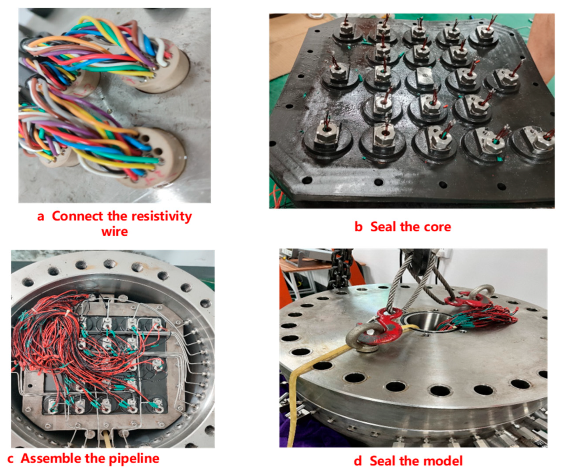
3.1. Installation and Debugging of Three-Dimensional Large Model

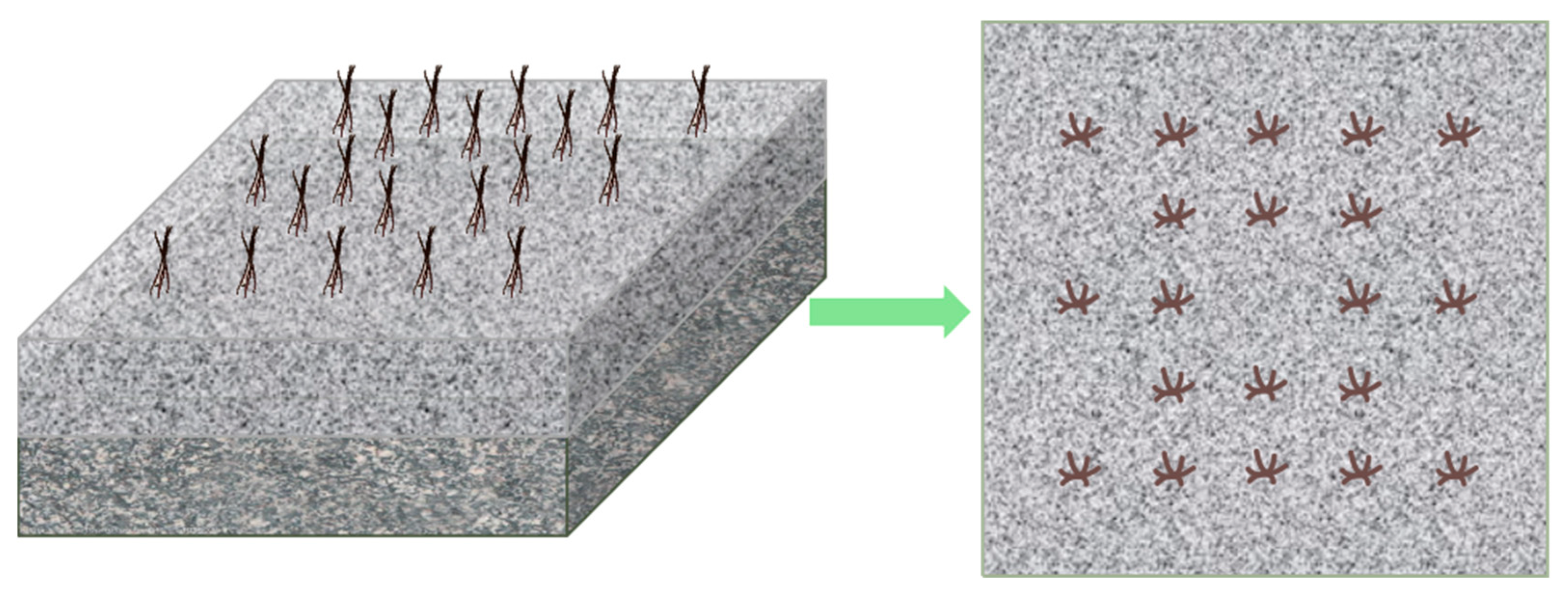
3.1.1. Embedding Probes into the Core

To understand the distribution of oil and water phases within the core structure, the resistivity at different positions within the core needs to be measured. A total of 40 pre-embedded probe points are designed, with pressure sensing lines connected. Each of the upper and lower layers of the core has 20 probes, as shown in Figure 3. The pre-embedded depth of the resistivity lines is 2.5 cm, and the reserved length of the resistivity lines outside the core is 20–30 cm. The inner diameter of the channel for the resistivity lines is 1.2 mm, and the diameter of the resistivity lines is 1 mm. The probes can measure the resistivity at various positions within the core. The resistivity values can be processed by software to obtain a three-dimensional core saturation distribution map, allowing the observation of saturated oil distribution and the changes in oil recovery and the sweep coefficient during CO2 flooding. The pressure sensing lines are used to observe the pressure changes at various positions within the core.

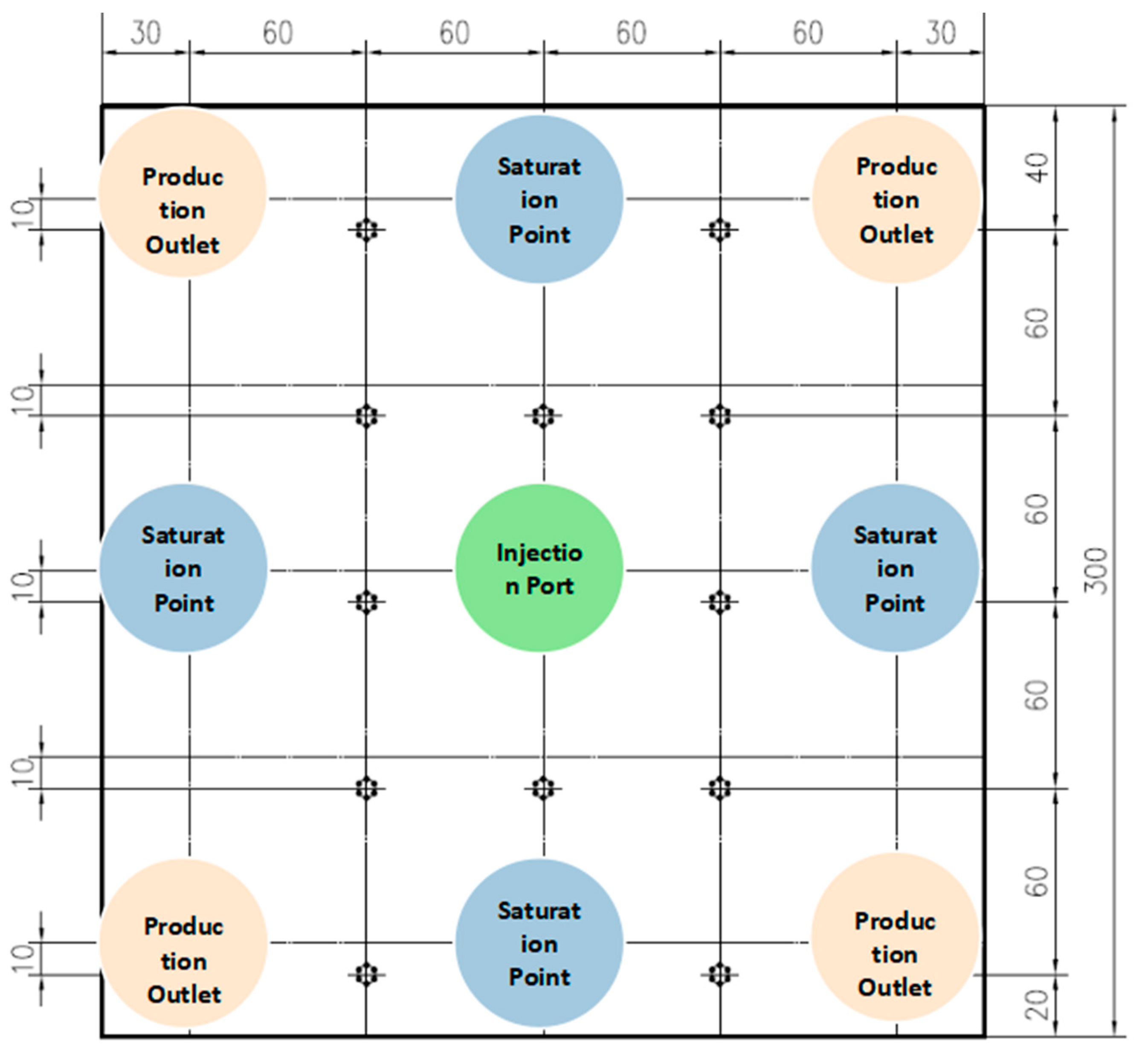
3.1.2. Core Sample Well Layout and Drilling

The experimental injection and production well network follows the five-point method. The injection well is drilled at the exact center of the top of the core sample, with an injection depth of 7.5 cm. The production wells are drilled at the four corners of both the high-permeability and low-permeability layers of the core, totaling eight wells, with a production depth of 3.5 cm. Additionally, to enhance saturation, four open wells are drilled at the center of each of the four edges on the top of the core, with a saturation enhancement depth of 7.5 cm. The diameter of all drilled holes is 0.3 cm. The distribution of the injection and production wells is shown in Figure 4.

3.1.3. Three-Dimensional Model Debugging and Installation

(1) Cleaning and Drying: First, clean the three-dimensional physical model and then dry it using an electric heating sleeve.
(2) Core Placement: Place the core sample into the rubber sleeve and sequentially connect the resistivity wires.
(3) Pipeline Assembly and Wiring: Assemble the pipelines and weld wires. Connect the distribution points of each probe on the core to the corresponding pressure measurement points on the three-dimensional physical model using pipelines for the subsequent fluid injection and pressure sensing. Then, use a soldering iron to weld the resistivity wires distributed at various locations on the core to the resistivity detector wires.
(4) Seal Inspection: Check the gas tightness of the rubber sleeve sealing the core. Pour white oil into the three-dimensional physical model and use an air compressor to introduce air into the injection end. Check if the rubber sleeve containing the artificial core is leaking. The white oil serves two purposes: first, to detect any leaks in the rubber sleeve; second, since white oil is non-conductive, it ensures the accuracy of resistivity measurements, as shown in Figure 5.
(5) Model Sealing: Install a back-pressure valve and other valves on the three-dimensional physical model and seal it with a cover.

3.1.4. Saturating the Core Sample

(1) Water Saturation:
Method: Inject water through the inlet end using a constant pressure mode to saturate the square core sample.
Procedure: To ensure complete saturation, two rounds of saturation are designed, with a total of 13 saturation points. The first round includes one injection point and eight production points as saturation distribution points, and the second round includes four additional saturation points.
Process: Switch the saturation points every 24 h. When the liquid stabilizes at the outlet end for a certain period, saturation is considered complete.
Post-Saturation: After completion, calculate the volume of saturated water and the porosity of the core sample.
(2) Oil Saturation:
Method: After water saturation, establish the oil saturation by displacing the water with oil at an injection rate of 0.5 mL/min.
Procedure: Follow the same steps as the water saturation.

3.2. Experimental Plan

Set the temperature of the three-dimensional model to 85 °C. Install four back-pressure tanks at the four outlet ends of the model and regulate the pressure to 25 MPa using a constant pressure mode. Conduct the experiment as follows:
(1) Alternating CO2–Water displacement:
Slug Size: 0.2 PV per slug.
Procedure: Inject a 0.2 PV slug of CO2 at a rate of 1 mL/min, followed by a 0.2 PV slug of formation water, as the first round of displacement. Perform five continuous cycles of CO2–Water alternating injection.
(2) Alternating CO2–Water combined with Foam flooding:
Procedure: Inject a 0.2 PV slug of CO2, followed by a 0.2 PV slug of foam solution during the water slug phase, as the first round of displacement. Perform five continuous cycles of CO2–Water alternating combined with foam injection.
(3) Alternating CO2–Water combined with imbibition agent flooding:
Procedure: Inject CO2 gas and an imbibition agent solution alternately into the core sample for the CO2–Water combined with imbibition agent composite displacement oil recovery experiment. The slug ratio of CO2 to surfactant solution is 1:1, with each slug consisting of 0.2 PV of CO2 and 0.2 PV of imbibition agent solution. Perform five continuous cycles of displacement, recording the fluid injection and production volumes throughout the experiment.
The total PV of CO2 and water injected in all three schemes is the same, as shown in Table 2.

4. Experimental Results and Analysis

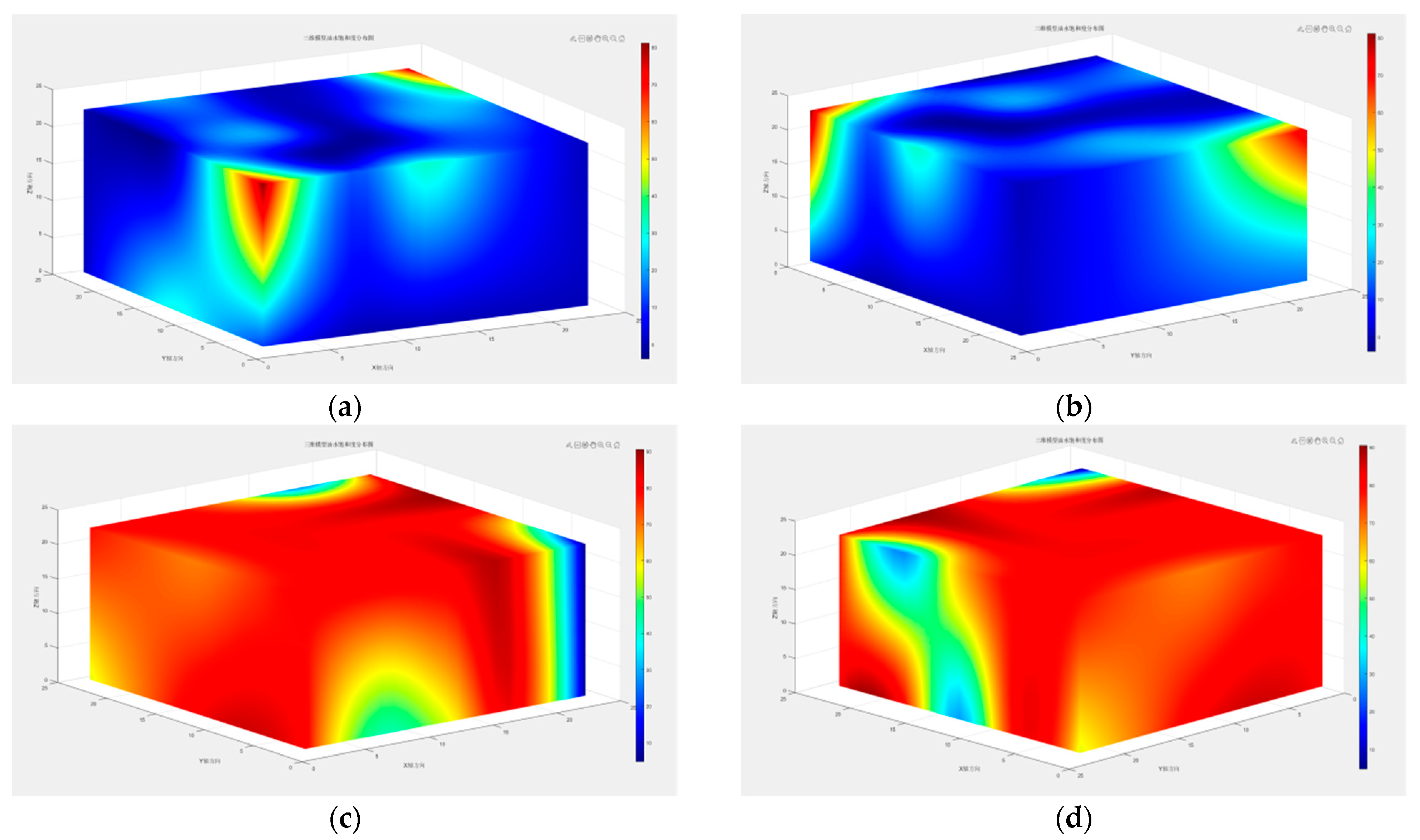
4.1. Residual Oil Distribution

Typically, the original oil in the reservoir is non-conductive, while the rock pore matrix becomes conductive when it contains water. The resistivity reflects the amount of oil and water; thus, the resistivity is used to characterize the saturation of the core. A lower resistivity value indicates a higher water content at that location, while a higher resistivity value represents a higher oil content. The three-dimensional saturation distribution of the core obtained through the three-dimensional physical modeling experiment and processed using Matlab is shown in Figure 6a–d. From the figure, it can be observed that regions closer to red represent higher resistivity, while regions closer to blue represent lower resistivity. The oil saturation in the first and second rounds was 52.1% and 58.7%, respectively. The saturation ratio in the second round increased by 6.6% compared to the first round. The unsaturated regions are mainly concentrated in the low-permeability layers and at the corners of the core. On the one hand, this is because the pore structure of low-permeability layers is denser, and on the other hand, the flow rate at the corners is lower, resulting in lower saturation levels.
The oil-water saturation distribution map is a preparatory simulation for CO2 flooding, providing a data basis for subsequent CO2 flooding. It can more intuitively reflect the distribution of remaining oil and more clearly show the distribution of oil and water. In addition, the saturation distribution map may more clearly indicate the seepage law of heterogeneous layers, visualizing CO2 flooding, and preparing for further evaluation of the effects of the three oil displacement methods in the later stage.

4.2. Experimental Results and Analysis of Different Oil Displacement Methods in Three-Dimensional Models

The production of oil, gas, water content, and recovery of each reservoir layer at the outlet of the core were measured separately, and the variation curves are shown in Figure 7. As depicted in Figure 7d, the recovery of the three displacement methods all sharply increased at first and then stabilized. Among them, the recovery of the CO2–Water alternating combined with an imbibition agent-enhanced displacement is the highest, followed by CO2–Water alternating combined with foam displacement, and finally CO2–Water alternating displacement, with a final recovery of 71.4%, 69.7%, and 55.1%, respectively. Compared with CO2–Water alternating displacement and CO2–Water alternating combined with foam displacement, the recovery of CO2–Water alternating combined with imbibition agent displacement increased by 16.3% and 1.7%, respectively. This is because, compared to foaming agents, imbibition agent-enhanced agents not only change the interfacial tension between oil and water in the pore throat of the core but also alter the wettability of the rock surface. The solution of surfactants reduces the interfacial tension between oil and water in the pore throat of the core, thereby improving the mobility of crude oil. Imbibition agents change the rock surface from hydrophilic to hydrophobic, reducing capillary forces in the pore throat. Therefore, the recovery of CO2–Water alternating combined with imbibition agent-enhanced displacement is the highest.
(1) Analysis of CO2–Water Alternating displacement Experiment Results
The final recovery of CO2–Water alternate injection is 55.1%, with a water content of 35.3% as shown in Figure 7c. With the switching of the plug segments during injection, there is some fluctuation, with a CO2 storage rate of 38.4%. The oil production (Figure 7a) of the core initially remains constant until 0.4 PV, after which it rapidly declines, with a slowed decline at 0.8 PV. conducted experiments on long cores to study the effect of CO2–Water alternate injection parameters on the development efficiency of low-permeability reservoirs. The experimental results show that moderate injection rates, a 0.2 PV plug segment, and alternating CO2–Water ratios of 1:1 can maximize oil recovery efficiency.
The CO2–Water alternate displacement drives oil towards the wellbore by alternating the injection of gas and water in intermittent cycles through pressure differences. Alternating water and CO2 injection reduces the fluidity ratio of water and oil, increases the gas volume sweep efficiency, and utilization rate. Due to the interaction between CO2 and water, there is also a certain interfacial tension during injection, forming a CO2–Water interface, which enhances oil recovery. CO2–Water alternate displacement can also change the permeability characteristics of the oil layer, increasing the effective permeability of the oil layer, thereby further improving recovery. Additionally, during injection, the microdynamic responses of the rock can cause the movement of oil and gas in the reservoir, promoting recovery. This method is applicable for oil and gas development in different types of reservoirs and under complex geological conditions.
CO2 injected under high temperature and pressure dissolves in the reservoir’s crude oil, reducing its viscosity and enhancing its flowability, thus improving oil recovery efficiency. Subsequent water injection significantly increases the internal water content of the core. During the process of reinjecting CO2 for oil displacement, some water filled in the core may be carried out, resulting in a slight decrease in water content, and resulting in a slight decrease in water content. When CO2 gas enters the three-dimensional model, it preferentially enters the reservoir with higher permeability, occupying large and medium pores, resulting in a higher gas content in larger pores. Subsequently, after the water plug enters, due to the Jiamin effect that gas is prone to occur in small throats, the injection pressure increases, forcing some injected water into the less permeable or smaller pores, thereby increasing oil recovery efficiency while expanding the macroscopic sweep area of water.
The injection of CO2 increases the content of carbonated water. A CO2 gas-free zone will form at the front of the carbonated water in the aquifer region, which in turn improves the mobility ratio between crude oil and water in the reservoir. Additionally, the CO2–Water solution has an acidifying effect, dissolving some rocks inside the core, increasing permeability, clearing crude oil flow channels, and increasing oil recovery efficiency. It can reduce the impact of reservoir heterogeneity to a certain extent, and has certain exploitation effects on reservoirs with low-permeability and strong vertical heterogeneity.
On the one hand, water injection advances significantly along high-permeability channels, forming a large number of inter-well bypass zones. On the other hand, injected CO2 has difficulty reaching crude oil in low-permeability layers. After gas channeling occurs in high-permeability areas, CO2 forms ineffective/low-efficiency cycles in these regions, inhibiting flow in low-permeability areas, resulting in lower oil recovery potential after gas breakthrough in low-permeability areas. CO2–Water alternate injection can significantly improve CO2 displacement efficiency. The water plug of alternate injection can form a water shield in front of CO2, controlling gas flow and delaying CO2 gas breakthrough. CO2–Water alternate displacement can effectively improve the development effect of low-permeability areas in heterogeneous reservoirs by alternately opening production wells, changing the main flow direction between injection and production wells, and is applicable for oil and gas development in different types of reservoirs and under complex geological conditions.
(2) Analysis of CO2–Water Alternating combined with Foam flooding Experiment Results
The final recovery of CO2–Water alternating combined with foam injection is 69.7%, with a water content of 34.5%. Initially, there is a significant decrease in water content, fluctuating with CO2–Water switching; the storage rate is 49.3%. There is a noticeable decline in oil production in the early stage, with a subsequent increase in oil production at 0.8 PV, and the core recovery increases with the volume of CO2–Water alternating combined with foam displacement. There is a significant increase in oil production at 1 PV, which continues until 1.5 PV, followed by stabilization. The reason is that after the third round of foam injection, the increasing trend of gas is effectively controlled, but it fails at 1.6 PV, showing a sharp increase. Comparative analysis reveals that after the foam liquid enters the porous medium, it forms a liquid film by squeezing the liquid phase in the pore and then continuously forms foam separation at the throat. Meanwhile, as the foam continuously moves, the surfactant carried in the foam liquid film significantly reduces the interfacial tension of oil and water in the porous medium. Therefore, CO2–Water alternating combined with foam displacement can reduce the fluidity ratio of oil and water on the one hand and significantly decrease the interfacial tension of oil and water on the other hand. Foam has the characteristics of emulsification, dispersion, and displacement. In a porous medium, foam has excellent shear, drag, and compression properties. After CO2–Water alternating combined with foam plug displacement, the residual oil in the pore medium is significantly reduced, and the overall recovery level is greatly increased, indicating that CO2–Water alternating combined with foam plug displacement can reduce the fluidity ratio of oil and water, interfacial tension, expand the sweep area, and improve recovery. During the CO2–Water flooding phase, injected water mainly advances in high-permeability cores. After water breakthrough in high-permeability cores, the diversion rate of high-permeability cores increases rapidly, forming water channeling in the core. After the foam injection, the foam flows quickly and selectively blocks the high-permeability cores. Foam has a higher flow resistance in high-permeability cores than in low-permeability cores, guiding subsequent fluids to enter low-permeability cores, further expanding the sweep range. Alternating the injection of CO2 and foam plugs can effectively affect the residual oil in some low-permeability areas. CO2–Water alternating combined with foam displacement can significantly reduce the water content, extend the effective period, block high-permeability layers effectively, increase the sweep volume of low-permeability areas, force subsequent water and CO2 gas to displace the residual oil in low-permeability layers, and significantly increase the recovery. Foam systems have the characteristics of plugging large pores without plugging small ones and plugging water without plugging oil, which can preferentially enter high-permeability layers for plugging. Foam systems can maintain a high resistance coefficient, effectively suppressing CO2 channeling in low-permeability strong heterogeneous reservoirs. Blocking high-permeability zones can greatly increase the recovery. CO2–Water alternating combined with foam displacement can effectively suppress fluid channeling in high-permeability bands and control CO2 flow. The lower the gas flow rate, the later the gas breakthrough occurs, and the higher the carbon storage rate. CO2–Water alternating combined with foam displacement has a higher microscopic oil recovery and higher pore utilization rate, which is conducive to long-term CO2 storage. CO2–Water alternating combined with foam alternating displacement can more evenly increase the sweep range of the entire area, increase the utilization rate of reserves in difficult-to-recover corner areas, and is suitable for the development adjustment stage of strongly heterogeneous reservoirs or after gas channeling.
(3) Analysis of CO2–Water Alternating combined with imbibition agent flooding Experiment Results
The final recovery of CO2–Water alternating combined with imbibition agent injection is 71.4%, with a water content of 33.3%. The crude oil recovery continuously increases with the increase in the volume of CO2 and imbibition agent injection. Before 0.6 PV, the crude oil recovery increases rapidly at a certain slope, but after reaching 0.6 PV, the rate of increase slows down, although the increase is still significant. The crude oil production sharply decreases at 0.6 PV, gradually increases at 0.8 PV, and then declines again at 1.3 PV. This is because there is a large amount of crude oil in the early stage of the core, combined with the adsorption effect of some surfactants, resulting in a significant increase in crude oil recovery. In the later stage, the amount of crude oil in the core decreases, and the adsorption effect of surfactants gradually becomes dominant. The surfactant solution will seep out a small amount of crude oil, which will be extracted under the propulsion of CO2 gas, so the increase in crude oil recovery in the later stage is small. When imbibition agents are injected into the reservoir, they form high adsorption areas in low-permeability areas, reducing the surface tension between gas and oil–water, improving the permeability of the reservoir and increasing the flowability of water inside the reservoir. Coupled with liquid flow, crude oil is squeezed out from the pores of the reservoir, effectively promoting the diffusion and movement of oil in the reservoir. Additionally, the action of capillary force reduces the adhesion force between rocks and crude oil, thereby improving the flowability of crude oil and consequently increasing the recovery. This injection method is suitable for the development adjustment stage of low-permeability reservoirs.

5. Conclusions

(1) On the one hand, alternating CO2 and water flooding combined with foam flooding can reduce the oil–water mobility ratio; on the other hand, it can significantly reduce the oil–water interfacial tension. After entering the porous medium, the foam fluid forms a liquid film by squeezing the liquid phase in the pores, and then continuously forms separated foam at the throat. Meanwhile, as the foam continues to migrate, the surfactants carried in the foam film significantly reduce the oil–water interfacial tension in the porous medium, effectively enhancing oil recovery. Alternating CO2 and water flooding combined with imbibition agents can further increase oil recovery to a greater extent. The injection of imbibition agents into the oil reservoir forms high-adsorption areas in regions with low permeability, reducing the surface tension between gas, oil, and water. While decreasing the surface tension, it can improve wettability, increase reservoir permeability, and enhance water mobility within the reservoir. Together with liquid flow, this process forces the crude oil out of reservoir pores, effectively promoting oil diffusion and movement. Additionally, capillary forces reduce adhesion between the rock and crude oil, thereby enhancing oil mobility and ultimately increasing oil recovery. This injection method is most suitable for heterogeneous reservoirs.
(2) The CO2–Water alternating combined with an imbibition agent compound drive achieves the best effect, with a recovery of 71.4%. The recovery for CO2–Water alternating drive and CO2–Water alternating combined with foam drive are 55.1% and 69.7%, respectively. Compared to the CO2–Water alternating drive and CO2–Water alternating combined with foam drive, the recovery increases by 16.3% and 1.7%, respectively. The CO2–Water alternating combined with an imbibition agent compound drive significantly improves the washing efficiency, mainly targeting the residual oil in the flow channels. It reduces interfacial tension while greatly improving wettability, addressing the issue of CO2 being unable to enter small pores under low-pressure differential environments.
(3) The resistivity values measured through three-dimensional physical modeling experiments show that the oil saturations in the first and second rounds are 52.1% and 58.7%, respectively, indicating a 6.6% increase in saturation from the first to the second round. In heterogeneous reservoirs, fluids injected into the three-dimensional core physical model preferentially flow to high-permeability zones, resulting in relatively poor oil recovery in low-permeability layers. Furthermore, under high temperature and pressure, the dissolution of carbon dioxide in crude oil reduces its viscosity, significantly improving its flowability and thereby enhancing oil recovery.

Author Contributions

Conceptualization, Y.L. and F.N.; methodology, Y.L.; software, B.Z.; validation, F.N., Y.L. and B.Z.; formal analysis, F.N.; investigation, T.L.; resources, Y.H.; data curation, Y.L.; writing—original draft preparation, Y.L.; writing—review and editing, Y.L.; visualization, Y.L.; supervision, F.N.; project administration, F.N. All authors have read and agreed to the published version of the manuscript.

Funding

This research received no external funding.

Data Availability Statement

The data presented in this study are available on request from the corresponding author.

Conflicts of Interest

The authors declare no conflict of interest.

References

  1. Shi, W.; Gong, Y.; Tao, L.; Bai, J.; Xu, Z.; Zhu, Q.; Ma, Y. Research for Flow Behavior of Heavy Oil by CO2 Foam Viscosity Reducer-Assisted Steam (CFVAS) Flooding: Microscopic Displacement Experiment Study. Processes 2024, 12, 1582. [Google Scholar] [CrossRef]
  2. Wang, X.; Yang, H.; Wang, W.; Li, J.; Liang, Q. Advances in Enhanced Oil Recovery Techniques for Low-Permeability Reservoirs in Yanchang Oilfield. Pet. Geol. Recovery Effic. 2022, 29, 69–75. [Google Scholar]
  3. Chen, Z.; Dong, Y.; Hu, H.; Zhang, X.; Tang, S. Evaluation of the Synergistic Oil Displacement Effect of a CO2 Low Interfacial Tension Viscosity-Increasing System in Ultra-Low Permeability Reservoirs. Processes 2024, 12, 1476. [Google Scholar] [CrossRef]
  4. Kong, D.; Gao, Y.; Sarma, H.; Li, Y.; Guo, H.; Zhu, W. Experimental investigation of immiscible water-alternating-gas injection in ultra-high water-cut stage reservoir. Adv. Geo-Energy Res. 2021, 5, 139–152. [Google Scholar] [CrossRef]
  5. Zhang, T.; Sun, Z.; Feng, D.; Zhao, W. Advances in Enhancing Unconventional Oil/Gas Recovery. Processes 2024, 12, 1386. [Google Scholar] [CrossRef]
  6. Zhang, Y.; Feng, H.; Zhai, Y.; Zhou, X.; Liu, D.; Wang, K. Study on the Mechanism and Laws of Improving Oil Recovery by CO2 Pressure Drive in Low-Permeability Heavy Oil Reservoirs. Pet. Drill. Tech. 2024, 52, 1–18. [Google Scholar]
  7. Song, R.; Tang, Y.; Wang, Y.; Xie, R.; Liu, J. Pore-Scale Numerical Simulation of CO2–Oil Two-Phase Flow: A Multiple-Parameter Analysis Based on Phase-Field Method. Energies 2022, 16, 82. [Google Scholar] [CrossRef]
  8. Zhang, K.; Zhang, L.; Liu, D. Recent Trends and Development Recommendations for Oil and Gas Exploration and Development in China. Acta Pet. Sin. 2022, 43, 15–28+111. [Google Scholar]
  9. Wei, Y.; Dong, Y.; Chen, Z.; Zhang, X.; Hu, H.; Tang, S. Research Progress on CO2 Injection Techniques for Improving Oil Recovery in Oil and Gas Reservoirs. Fine Petrochem. 2024, 41, 69–74. [Google Scholar] [CrossRef]
  10. Du, Y.; Zhang, H.; Li, X.; Zhang, Y.; Yuan, S. A Molecular Dynamics Study On The Suitable Compatibility Conditions Of CO2-Cosolvent-Light Hydrocarbon System By Calculating the Solubility Parameters. Energy Fuels 2020, 34, 3483–3492. [Google Scholar] [CrossRef]
  11. Wang, Q.; Yang, S.; Bai, J.; Qian, K.; Li, J. Effects of CO2 Injection Methods on Oil Recovery and Reservoir Damage in Heterogeneous Multilayer Reservoirs. Acta Pet. Sin. 2020, 41, 875–884+902. [Google Scholar]
  12. Cao, C.; Chen, X.; Zhang, L.; Zhao, Y.; Wen, S.; Zhao, Z.; Yang, B.; Zhu, H. Research Progress on CO2 Injection for Improving Oil Recovery and Storage Evaluation Methods in Gas Reservoirs. Sci. Technol. Eng. 2024, 24, 7463–7475. [Google Scholar]
  13. Shi, Y.; Jia, Y.; Pan, W. Mechanism of Supercritical CO2 Injection for Enhanced Recovery in Low-Permeability Tight Gas Reservoirs. Oil Gas Geol. 2017, 38, 610–617. [Google Scholar]
  14. Li, R.; Jiang, P.; He, D.; Chen, X.; Xu, R. Experimental Investigation on the Behavior of Supercritical CO2 during Reservoir Depressurization. Environ. Ecience Technol. 2017, 51, 8869–8876. [Google Scholar] [CrossRef] [PubMed]
  15. Zhou, X.; Zhou, D.; Deng, J.; Deng, J.; Ray, R.; Jiang, Z. Experimental Study on Enhancing Recovery of Tight Oil Reservoirs Using Supercritical CO2 Flooding. Spec. Oil Gas Reserv. 2021, 28, 118–123. [Google Scholar]
  16. Zhang, J.; Li, J.; Zhang, W.; Sheng, G.; Dong, H. Experimental and Application Evaluation of CO2 Miscible Flooding for Enhanced Oil Recovery in Conglomerate Reservoirs. Daqing Pet. Geol. Dev. 2024, 1–10. [Google Scholar] [CrossRef]
  17. Jin, X.; Du, M.; Lv, W.; Hao, C.; Yao, L. Reservoir Characteristics of the Chang 6 Member in the Erdos Basin and Experimental Study on Improving Oil Recovery by CO2 Flooding. Oil Gas Geol. Recovery Effic. 2024, 1–13. Available online: http://kns.cnki.net/kcms/detail/37.1359.TE.20240513.1724.001.html (accessed on 2 August 2024).
  18. Qu, F.; Wang, Q.; Tong, S.; Deng, S. Mechanism and Parameter Optimization of CO2 Injection for Enhancing Oil Recovery in Gulong Shale Oil through Supplemental Energy. Daqing Pet. Geol. Dev. 2024, 1–7. [Google Scholar] [CrossRef]
  19. Liu, X.; Zheng, X.; Qian, D.; Gao, H.; Tan, T.; Pu, W. Laboratory Study on Enhanced Oil Recovery in Tahe Strong Bottom Water Sandstone Reservoirs by Gas-Water Alternating Injection with N_2 Mixed Gas. J. Yangtze Univ. (Nat. Sci. Ed.) 2022, 19, 57–64. [Google Scholar] [CrossRef]
  20. Zhang, G.; Li, D.; Jia, G.; Deng, C.; Jia, Z. Laboratory Study on CO2 Flooding in Long Cores from Huabei Oilfield. Pet. Geol. Eng. 2022, 36, 77–81. [Google Scholar]
  21. Zhang, L.; Tan, X.; Jiao, Y. Experimental and Numerical Simulation Study on Enhanced Oil Recovery by CO2 Micro-Foam Flooding in Offshore Low-Permeability Reservoirs. China Offshore Oil Gas 2023, 35, 145–153. [Google Scholar]
  22. Yuan, D. Three-Dimensional Physical Simulation Study on Enhanced Oil Recovery by N2 Foam/CO2 Cyclic Injection. Pet. Drill. Tech. 2022, 50, 126–132. [Google Scholar]
  23. Ren, S.; Du, X.; Sun, Z. Research Progress on Gas-Water Alternating Injection and Foaming Agent Systems for Enhanced Oil Recovery. J. China Univ. Pet. (Ed. Nat. Sci.) 2022, 46, 102–108. [Google Scholar]
  24. Zhang, L.; Xie, H.; Wang, R.; Fu, G.; Xu, S.; Deng, C. Development and Performance Study of High-Foaming and Strong Imbibition Displacement Agents for Tight Oil Reservoirs. Mod. Chem. Ind. 2024, 44, 155–162. [Google Scholar] [CrossRef]
  25. Yang, Y.; Zhang, S.; Cao, X.; Lyu, Q.; Lyu, G.; Zhang, C.; Li, Z.; Zhang, D.; Zheng, W. Theoretical Technology and Field Practice of CO2 High-Pressure Miscible Displacement and Sequestration in Shengli Oilfield. Pet. Explor. Dev. 2024, 1–12. Available online: http://kns.cnki.net/kcms/detail/11.2360.TE.20240731.1012.002.html (accessed on 3 August 2024).
  26. Yang, Z.; Wu, W.; Dong, Z.; Lin, M.; Zhang, S.; Zhang, J. Reducing the Minimum Miscibility Pressure of CO2 and Crude Oil Using Alcohols. Colloids Surf. A Physicochem. Eng. Asp. 2019, 568, 105–112. [Google Scholar] [CrossRef]
  27. Liu, H.; Zhao, J.; Zheng, J.; Wu, B.; Zuo, Q.; Hu, X.; Wu, Q. Experimental Study on the Feasibility of CO2 Miscible Flooding in Offshore Low-Permeability Reservoirs. Unconv. Oil Gas 2024, 11, 74–79. [Google Scholar] [CrossRef]
  28. Zhang, K.; Perdomo, M.E.; Kong, B.; Sebakhy, K.O.; Wu, K.; Jing, G.; Han, J.; Lu, X.; Hong, A.; Chen, Z. CO2 Near-Miscible Flooding for Tight Oil Exploitation. In Proceedings of the SPE Asia Pacific Unconventional Resources Conference and Exhibition, Nusa Dua, Bali, Indonesia, 9–11 November 2015. [Google Scholar]
  29. Yuan, S.; Ma, D.; Li, J.; Zhou, T.; Ji, Z.; Han, H. Progress and Prospect of Industrialization of Carbon Dioxide Capture, Oil Displacement, and Sequestration. Pet. Explor. Dev. 2022, 49, 828–834. [Google Scholar] [CrossRef]
  30. Li, Y.; Sui, X.; Li, B. Laboratory Study on Methods for Enhanced Oil Recovery After Polymer Flooding. Acta Pet. Sin. 2008, 3, 405–408. [Google Scholar]
  31. Lan, J.; Tang, F.; Xie, D.; Liang, X.; Wang, G. Experimental Study on CO2 Flooding for Enhanced Oil Recovery in Tight Oil Reservoirs. Contemp. Chem. Ind. 2023, 52, 997–1001. [Google Scholar] [CrossRef]
  32. Cao, J.; Li, N.; Wang, X. Current Status of CO2 Injection Technology for Enhanced Oil Recovery in Tight Oil Reservoirs. Shandong Chem. Ind. 2022, 51, 133–135. [Google Scholar] [CrossRef]
  33. Li, S.; Tang, Y.; Hou, C. Current Status and Development Trends of CO2 Injection Technology for Enhanced Oil Recovery. Reserv. Eval. Dev. 2019, 9, 1–8. [Google Scholar] [CrossRef]
  34. Hu, S.; Tao, S.; Yan, W.; Yang, Z.; Men, G.; Tang, Z.; Xue, J.; Chen, X.; Jia, X.; Jiang, T.; et al. Advances on Enrichment Law and Key Technologies of Exploration and Development of Continental Tight Oil in China (2016–2018). J. Nat. Gas Geosci. 2019, 4, 297–307. [Google Scholar] [CrossRef]
  35. Abedini, A.; Torabi, F. On the CO2 storage potential of cyclic CO2 injection process for enhanced oil recovery. Fuel 2014, 124, 14–27. [Google Scholar] [CrossRef]
  36. Rezk, M.G.; Foroozesh, J. Determination of mass transfer parameters and swelling factor of CO2-oil systems at high pressures. Int. J. Heat Mass Transf. 2018, 126, 380–390. [Google Scholar] [CrossRef]
  37. Mohamed, I.M.; Nasr-El-Din, H.A. Formation damage due to CO2 sequestration in deep saline carbonate aquifers. In Proceedings of the SPE International Symposium and Exhibition on Formation Damage Control, Society of Petroleum Engineers, Lafayette, LA, USA, 23–24 February 2022. [Google Scholar]
  38. Zhang, K.; Seetahal, S.; Alexander, D.; Lv, J.; Hu, Y.; Lu, X.; Zhang, D.; Wu, K.; Chen, Z. Effect of Confinement on Gas and Oil Relative Permeability During CO2 Flooding in Tight Oil Reservoirs. In Proceedings of the SPE Trinidad and Tobago Section Energy Resources Conference, Virtual, 13–15 June 2016. [Google Scholar]
  39. Huang, C.; Huo, L.; Wu, C. Progress and Prospect of CO2 Resource Utilization Technology Based on Unconventional Oil and Gas Development. Unconv. Oil Gas 2022, 9, 1–9. [Google Scholar] [CrossRef]
  40. Assef, Y.; Kantzas, A.; Almao, P.P. Numerical Modelling of Cyclic CO2 Injection in Unconventional Tight Oil Resources; Trivial Effects of Heterogeneity and Hysteresis in Bakken Formation. Fuel 2019, 236, 1512–1528. [Google Scholar] [CrossRef]
  41. Lv, G.; Li, Q.; Wang, S.; Li, X. Key Techniques of Reservoir Engineering and Injection-Production Process for CO2 Flooding in China’s SINOPEC Shengli Oilfield. J. CO2 Util. 2015, 11, 31–40. [Google Scholar] [CrossRef]
  42. Ding, M.; Wang, Y.; Wang, Y.; Gao, M.; Liu, D.; Chen, W. Experimental Investigation of Bypassed-Oil Recovery via CO2 Soaking and Huff and Puff Injection: Effects of Miscibility and Bypassed-Oil Size. Fuel 2019, 248, 152–160. [Google Scholar] [CrossRef]
  43. Zhang, B.; Nie, F.; Deng, X.; Wang, Y.; Hou, B. Evaluation of an Oxygen-Reduced Air Flooding Plugging System and Its Injection Method in the Honghe Oilfield. Energy Fuels 2022, 36, 12524–12532. [Google Scholar] [CrossRef]
  44. Zhou, J.; Zhang, B.; Lei, Z.; Shao, X.; Guan, Y.; Cao, R. Core Experiments and Oil Enhancement Mechanism of Unstable Water Injection in Low-Permeability Reservoirs. Xinjiang Pet. Geol. 2022, 43, 491–495. [Google Scholar]
Figure 1. Longitudinal Heterogeneity Diagram of the Core.
Processes 12 01843 g001
Figure 2. Experimental Flowchart.
Processes 12 01843 g002
Figure 3. Probe Distribution.
Processes 12 01843 g003
Figure 4. Wellbore distribution.
Processes 12 01843 g004
Figure 5. Model Debugging and Installation Process.
Processes 12 01843 g005
Figure 6. Saturation Distribution Cloud Map. (a) First round of water saturation. (b) Second round of water saturation. (c) First round of oil saturation. (d) Second round of oil saturation.
Processes 12 01843 g006
Figure 7. Comparison chart. (a) Oil production. (b) gas production. (c) water content. (d) recovery.
Processes 12 01843 g007
Table 1. Ionic Composition of Formation Water.
Ion TypeK+ + Na+Mg2+Ca2+HCO3SO42−ClTotal SalinityWater TypepH
Salinity mg/L18,736.154.7216.43624.5178.11054.723,947.3NaHCO36.2
Table 2. Injection Scheme Design Table.
Comparative SchemeFirst Round
Injection Volume
(PV)
Second Round
Injection Volume
(PV)
Third Round
Injection Volume
(PV)
Fourth Round
Injection Volume
(PV)
Fifth Round
Injection Volume
(PV)
Alternating displacement of CO2 and WaterCO2Water CO2Water CO2WaterCO2WaterCO2Water
0.20.20.20.20.20.20.20.20.20.2
Alternating CO2–Water combined with Foam floodingCO2foamCO2foamCO2foamCO2foamCO2foam
0.20.20.20.20.20.20.20.20.20.2
Alternating CO2–Water combined with Surfactant floodingCO2imbibition agentCO2imbibition agentCO2imbibition agentCO2imbibition agentCO2imbibition agent
0.20.20.20.20.20.20.20.20.20.2
Disclaimer/Publisher’s Note: The statements, opinions and data contained in all publications are solely those of the individual author(s) and contributor(s) and not of MDPI and/or the editor(s). MDPI and/or the editor(s) disclaim responsibility for any injury to people or property resulting from any ideas, methods, instructions or products referred to in the content.

