Article

Hybrid Water Disinfection Process Using Electrical Discharges

by
Antonina P. Malyushevskaya
1,*,
Piotr Koszelnik
2,
Olena Mitryasova
3,
Anna Yushchishina
1,
Andrii Mats
3,
Dorota Papciak
2 and
Monika Magdalena Zdeb
2,*
1
Institute of Impulse Processes and Technologies of NAS of Ukraine, Bohoyavlensky Avenue, 43a, 54018 Mykolaiv, Ukraine
2
Faculty of Civil, Environmental Engineering and Architecture, Rzeszow University of Technology, al. Powstancow Warszawy 6, 35-959 Rzeszow, Poland
3
Department of Ecology, Petro Mohyla Black Sea National University, 68 Desantnykiv Street, 10, 54003 Mykolaiv, Ukraine
*
Authors to whom correspondence should be addressed.
Processes 2024, 12(9), 1846; https://doi.org/10.3390/pr12091846
Submission received: 18 June 2024 / Revised: 14 August 2024 / Accepted: 22 August 2024 / Published: 29 August 2024
(This article belongs to the Section Chemical Processes and Systems)

Abstract

:
An analysis of the physical and chemical phenomena accompanying electrical discharges is carried out, and the main factors influencing microorganisms’ abatement are studied. The similarity of the cavitation processes in water systems induced by underwater electric discharges and ultrasound is experimentally demonstrated. The characteristic features of electrical discharge in the cavitation mode, providing effective water disinfection with electric discharges with a significantly reduced amount of active chlorine, are identified in order of importance. The inactivation of microorganisms is intensified, firstly, by the generation of chemically active particles from the water medium itself, due to the integral action of the electro-discharge cavitation of the whole treated volume, and by local shock waves, acoustic flows, and ultraviolet radiation in the area near the cavitating bubbles. The main advantages of electric discharge cavitation over ultrasonic range are the wider range of high-frequency acoustic radiation inherent in an electric discharge, the high intensity and power of the cavitation processes, and the possibility of a significant increase in the volume of disinfected liquid. This study allows for a better understanding and prediction of the bacterial effects that occur during a high-voltage underwater electrical discharge.

1. Introduction

The sustainable management of water resources by ensuring the availability of clean and hygienic water is one of the 17 Sustainable Development Goals (SDGs) adopted for 2015–2030, corresponding to 169 tasks [1,2,3,4,5]. The active development of water recycling methods requires the assurance of adequate microbiological quality. To this end, research is being conducted on disinfection methods that would be highly effective with minimal costs and short treatment cycle times.
Advanced oxidation processes (AOPs) and reverse osmosis (RO) are considered the most effective water recycling technologies, but these methods can be costly, or have severe limitations in terms of the amount of water processed per unit, the time involved, and the amount of contaminants removed or the formation of byproducts [6,7]. Reverse osmosis requires a high energy input to pump the liquid through the membrane system, which should be maintained and replaced routinely, and sometimes requires a combination of water purification with oxidants in the pretreatment stages. Advanced oxidation processes require the active use of chemical precursors for the synthesis of active hydroxyl radicals, and AOPs also involve relatively long water treatment cycles. In the search for a compromise between oxidation efficiency and the minimization of byproduct formation, modern water treatment plants use the technique of multipoint dosing of chemical oxidants in smaller doses [8], and technologies are being sought that can effectively remove byproduct precursors—especially organic compounds and bromides [9,10,11,12].
In spite of the progress in AOPs and RO, chlorination currently holds the undisputed lead in terms of the scale of its use in water disinfection. Chlorination allows for the effective inactivation of a wide range of pathogens commonly found in wastewater, leaves a residue in the water that is easily measured and controlled, is economical, and has an extensive track record of successful use in water treatment improvement [13,14,15]. Chlorine for water disinfection is available in several different forms: gas (Cl2), sodium hypochlorite solution (NaOCl), calcium hypochlorite (Ca(OCl)2), and chlorine dioxide (ClO2). When chlorine in any form is added to water, hydrolysis (Cl2 + H2O ↔ HOCl + H+ + Cl or Ca(OCl)2 + 2H2O ↔ 2HOCl + Ca(OH)2 or NaOCl + H2O ↔ HOCl + NaOH) and ionization (HOCl ↔ H+ + OCl) occur to form hypochlorous acid (HOCl) and hypochlorite ions (OCl). The resulting hypochlorous acid and hypochlorite ions realize the inactivation of microorganisms as follows: oxidize the cell protoplasm, precipitate the protein, modify the cell wall permeability, and digest the cell walls [14]. However, chlorination has some serious disadvantages. Chlorine residuals are toxic to aquatic life and require dechlorination; chlorine oxidizes certain types of organic matter in wastewater, creating hazardous byproducts; chlorine residuals are unstable in the presence of high concentrations of chlorine-demanding materials, thus requiring higher doses to effect adequate disinfection; and all forms of chlorine are highly corrosive and toxic; therefore, its storage, shipping, and handling pose a risk, requiring increased safety regulations. Thus, the reduction in active chlorine use in water disinfection processes is an important environmental issue. However, to maintain the effectiveness of disinfection, it is reasonable to replace part of the active chlorine with other active chemical particles that have a less harmful effect on the environment.
Therefore, the increasing chemicalization of atmospheric air, soil, food, and water is driving the search for methods to limit the use of chemical substances. The use of plasma in various areas of human activity is of increasing interest to the scientific and research communities, including in water treatment processes. Plasma technologies are advanced oxidation methods and are promising due to their efficiency and environmental friendliness [16]. Plasma water treatment technologies also include treatment using electrical discharges, which are one of the simplest ways to create plasma states of matter. Their associated phenomena can be used to enhance chemical and technological processes in water treatment systems, including the inactivation of microorganisms [17,18,19,20,21]. The use of physical factors, such as electrical discharges, could reduce the concentration of chemical disinfectants required and prevent the formation of harmful byproducts.
In our experimental research work [22], the decisive influence of volumetric cavitation, which occurs under certain conditions with an electric discharge, on the disinfection process was experimentally confirmed. The use of electro-discharge cavitation reduces the bactericidal dose of chlorine to 0.4–0.5 mg/dm3, with energy costs for the electric discharge effect of about 25 kJ/dm3, and significantly reduces the time for the chlorination process, while providing a prolonged bactericidal effect. However, an electric discharge, especially in the cavitation mode, has many effects that influence microorganisms’ abatement in different ways and to different degrees.
According to modern ideas, the main causes of the inactivation of microorganisms are as follows:
-
The rupture of the cell wall;
-
Changes in cell permeability;
-
The modification of the nature of the protoplasm (e.g., disruption of the colloidal structure);
-
The induction of abnormal redox processes;
-
Changes in the structure of nucleic acids, resulting in a restriction of protein synthesis in the cell [7,23,24].
Therefore, the aim of this research is to identify the factors that occur during the electrical discharge in water in the cavitation mode, causing the inactivation of microorganisms and ensuring the reduction in disinfectants, when the treated water is simultaneously exposed to an electric discharge and chemical reagents.

2. Materials and Methods

2.1. Experimental Setup for Electric Discharge Realization

The preliminary stage of the electrodischarge treatment of polluted water [22] was carried out in an experimental electrodischarge installation (Figure 1). The same laboratory installation was the source of pulses during the research of the acoustic spectrum of electric discharge in cavitation mode. The pulse generator is a proprietary development of the Institute of Pulse Processes and Technologies of the National Academy of Sciences of Ukraine.
The high-voltage pulse generator was connected to the industrial three-phase mains supply. The generator contained three identical inductors (1), three identical high-voltage capacitors (2), the three-phase high-voltage rectifier (3), the capacitive energy storage device (4), the high-voltage switch (5), and the electrode system (6). The electrode system (6) is placed in the working chamber along its axis. In general, the anode electrode is a metal rod placed in an insulating casing (in our case, the casing material was fluoroplastic). The part of this electrode that protrudes from the insulating body is called the uninsulated end of the anode. The diameter of the current-carrying steel rod (anode) was 8 mm, and its tip was sharpened to a hemisphere with a radius of 4 mm. The working chamber in our case was a metal parallelepiped with durable organic glass windows for high-speed recording of what happens in the liquid during an electric discharge. The bottom of the metal working chamber is the counter electrode (cathode). The high-voltage pulse generator is equipped with a protection system (7), a three-phase frequency converter (8), and a dividing capacitor (9).
The experimental installation can provide an operating voltage (U) from 15 to 25 kV, the capacity of the capacitor bank (C) can be varied from 0.1 to 1 μF, and the inductance of the discharge circuit can be varied from 1 to 3 μH. While studying the acoustic spectrum of the electrical discharge in cavitation mode, we iterated the most efficient mode of water treatment from [22]: operating voltage 25 kV, energy storage capacity 0.25 μF, and pulse frequency 1 Hz. The study of the discharge current of underwater electric discharges and their acoustic spectrum was carried out by varying the inductance of the discharge circuit and the length of the uninsulated end of the electrode–anode in the discharge gap.

2.2. Measurement of the Frequencies of the Electric Discharge’s Acoustic Radiation

It is important to note that three of the five causes of microbial inactivation listed above are specified by the interaction between the cell and chemically reactive particles. It is, therefore, necessary to create conditions for the occurrence of such particles in the medium treated by the electric discharge. The occurrence of chemical reactions is related not only to the collapse of the bubbles formed, but also to their ability to resorb [25]. Gas bubbles suspended in a liquid medium undergo periodic contraction and expansion, i.e., pulsation at a certain frequency. The natural frequency of such a bubble f for small amplitudes is given by Formula (1):
f = 1 2 π R max 3 γ p 0 ρ p 0 + 2 σ r ,
where r is the radius of the bubble at a given stage of compression, p0 is the external pressure, Rmax is the maximum radius of the bubble, γ is the ratio of the heat capacity of the gas filling the bubble at constant pressure to its heat capacity at constant volume (polytropic indicator), σ is the surface tension of the liquid, and ρ is the density of the liquid. Since the double ratio of the surface tension to bubble radius is extremely small compared to the initial pressure, Formula (1) is simplified to Formula (2):
f = 1 2 π R max 3 γ p 0 ρ .
Thus, at an external pressure of 0.1 MPa and all other conditions being equal, the natural frequency of an air bubble in water is determined by its radius. The amplitude and energy of the pulsations of the gas bubbles in the liquid are maximized when the natural frequency of the pulsating bubble coincides with the frequencies of the acoustic waves in the liquid (resonance). It is these resonant bubbles that ensure the powerful cavitation and the occurrence of chemical processes in the acoustic field. As our early experimental studies [26] have shown, up to 60% of the initial bubbles in the cavitation zone of an electric discharge reactor have a characteristic maximum diameter of 0.2 to 2 mm, their resonance frequency is in the range of 15–35 kHz; the rest of the bubbles in the cavitation zone have a maximum diameter of 0.1 to 0.05 mm, the resonance frequency of these bubbles is in the range of 70–125 kHz. The diameter of gas bubbles in water was measured by the analysis of digital photographic images using a developed computer program. We used a high-speed photo-recorder SFR-1. The technique for measuring bubble size is described in detail in [26]. Based on the data from this work, we designed our experiments to establish such a spectrum of acoustic radiation from an electric discharge that would allow the bubbles–nuclei that had been present in the liquid.
Therefore, the obvious way to achieve powerful cavitation is to create acoustic waves of the above frequencies in the working liquid. Then, almost all the bubbles in the medium will become resonant and the conditions for the maximum generation of chemically reactive particles will be created. In the research [27], the existence of frequencies of 15–35 kHz of sufficient intensity in the spectrum of acoustic radiation of underwater electric discharge was shown. The frequency range of 70–125 kHz of the acoustic radiation of an electric discharge has not been investigated. The presence of a large number of bubbles, which could resonate in this frequency range, can have a decisive influence on the intensity of cavitation and related processes.
One of the objectives of this research towards this goal is to demonstrate the generation of acoustic radiation in the range of 70–125 kHz (high-frequency range) by electrical discharges in water. It is known that acoustic radiation shifts to the high-frequency region of the spectrum when the leading edge of the pressure pulse is shortened, allowing a rapidly expanding channel of electrical discharge to be created. From the physical basis of the theory of underwater electrical explosions, it is known that to obtain pressure pulses with a short leading edge, it is necessary to obtain a current pulse in which the leading edge has a duration of 1.2–1.5 times less than the duration of the pulse itself.
The installation described above (Figure 1) allows the duration of the leading edge of the current pulse to be varied over a wide range by changing the length of the uninsulated end of the electrode (Figure 1, item 6) and the inductance of the discharge circuit. To study the acoustic spectrum of the underwater electrical discharge, the electrode system was placed in the large three-dimensional basin of an acoustic measurement complex, electrical discharges were generated, and the effective water disinfection modes were repeated as in [22]. The Neptune Solar Limited Model D/140/H Underwater Sonic Detector was installed at a depth of 1 m from the axis of the discharge gap of the electrode system. The electrode system was placed in a 2.5 m deep pool at a distance of 1.5 m from the basin’s walls and 1 m from the free surface of the water, so that the waves reflected from the free surface could not distort the image of the acoustic field. Each set of measurements included 50 repetitions, the acoustic spectrum of the pressure pulses of the electric discharges was derived, and then the frequency histograms of the acoustic radiation of the underwater electric discharge were constructed.

3. Experimental Results

The characteristics of the current pulses obtained in the different electrical discharge modes in the acoustic measurement basin are shown in Table 1.
Obviously, by changing the length of the uninsulated part of the anode electrode and the inductance of the discharge circuit, it is possible to change the duration of the leading edge of the current pulse. In this case, there are modes (e.g., mode 3) in which the current pulse becomes significantly asymmetrical and the leading edge of the current pulse is very short compared to the duration of the entire pulse. It is important to note that the peak value of the current, in this case, is lower than that of the current pulse in mode 1, which was obtained with an extremely short uninsulated part of the anode electrode.
The analysis of the obtained spectrum (Figure 2) confirmed that the modes allowing us to obtain short leading edges of current pulses provide very short leading edges of acoustic pulses (2 μs for mode 1; 2.78 μs for mode 2; 3.2 μs for mode 3), which means a significant (up to 120 kHz) extension of the frequency band of acoustic radiation of underwater electric discharges in the ultrasonic range compared to those detected and described in [27].
It should be noted that the acoustic pressure obtained with the electric discharge in water in the range of 70 to 125 kHz is significantly lower compared to the acoustic radiation of an electric discharge in water in the range of 15 to 35 kHz [27], and are as follows: for the mode 1: 5·10−1 … 2·10−1 Pa; for the mode 2: 3·10−1 … 1·10−1 Pa; and for the mode 3: 1·10−2 … 1·10−3 Pa. Returning to Table 1, we can conclude that the intensity of the high-frequency part of the spectrum of acoustic radiation from an electric discharge in water can be also adjusted by the inductance of the discharge circuit and the length of the uninsulated end of the electrode–anode protruding into the discharge gap.
Thus, the obtained experimental results prove the occurrence and reveal the conditions for the emergence of the ultrasonic component in the range of 75 to 120 kHz in the hitherto unexplored range of acoustic radiation of underwater electric discharges. It is also shown that it is possible to create conditions for resonant excitation of the medium in the course of underwater electric discharges, including the resonance of initial bubbles with a diameter of less than 0.1 mm, which make up a significant part of the gas phase in the treated water. Therefore, the ultrasonic component of the acoustic radiation of an electric discharge in water is in the range of 20 to 125 kHz, and there is a possibility of activating gas or vapor bubbles in the working medium by analogy with the irradiation of such a medium with ultrasound.
It is this intensive treatment of water with broadband ultrasonic waves generated by an electric discharge that allows all the initial gas bubbles in the liquid to resonate. These resonant oscillations, in turn, ensure powerful cavitation in the liquid and the formation of a large amount of chemically reactive particles from the working medium itself, facilitating the inactivation of microorganisms. However, an electric discharge is not only a source of intense broadband ultrasonic radiation, but is also accompanied by other phenomena that have a destructive effect on microorganisms. Together with other factors of electric discharge described below, it allows us to significantly reduce the amount of infused chemical reagents for disinfection, as shown in Table 2 [22].

4. Discussion

Electric discharge cavitation and its inactivating effect on microorganisms are complex and multifaceted phenomena. The description of processes that occur as a result of electric discharge in cavitation mode required us to study a large amount of the scientific literature in order to develop hypotheses about the high efficiency of the simultaneous use of an electric discharge and reduced amounts of chemical reagents for water disinfection.

4.1. Physical Phenomena Accompanying Electric Discharge Cavitation

Obvious factors that are characteristic of an underwater electrical discharge affecting biological objects are ultraviolet and thermal radiation, primary pressure waves and secondary acoustic waves, and chemically reactive particles generated in the working medium. As high-intensity acoustic waves of high intensity propagate through the medium, nonlinear effects that depend on the amplitude of the wave (second-order effects) occur. These include acoustic flows (and the acoustic turbulence they cause) and pulsations of gas bubbles. Pulsations induce many accompanying phenomena: flotation, rectified diffusion, and local shock waves. Second-order phenomena include ponderomotive forces, surface effects, radiation pressure, and, actually, cavitation. Cavitation is accompanied by both flotation and rectified diffusion, as well as microfluidic flows, microjets, and local shock waves.
Acoustic streams are stationary vortex flows of fluid that occur in an inhomogeneous acoustic field, both in free space and in the vicinity of obstacles of various kinds. Acoustic streams can also occur in the vicinity of pulsating and oscillating bodies. The reason for the occurrence of different acoustic streams is the irreversible loss of energy and momentum of the acoustic wave in the medium. If an acoustic wave crosses an imaginary plane, the energy density of an incident wave from the side is greater than that of the same volume behind the plane, on the side of the passing wave. A force will therefore act on the plane, tending to move it away from the source of the acoustic vibrations. This force, equal to the energy density gradient and directed towards the propagation of the wave, causes the medium to move. Losses of the energy in the medium, which give rise to acoustic flows, can occur either in the entire volume occupied by the acoustic field or in a part of the volume. The greater the loss of acoustic energy in the medium, the more intense and faster the acoustic flows. It does not matter whether the loss mechanism is related to the viscosity of the medium or the inhomogeneity of the medium (suspended particles, gas bubbles, cavitation region). What matters is the irreversibility of the loss of energy and momentum of the acoustic wave [28]. The flows generated in an acoustic field are usually divided into three groups: flows in an inhomogeneous space of limited volume, flows generated outside the acoustic boundary layer, and flows generated in a viscous boundary layer in the vicinity of obstacles.
Ponderomotive forces include the Bjerknes force, the Stokes force associated with the change in viscosity, the force associated with the distortion of the waveform, and the force generated by the interaction of a pulsating bubble with an acoustic field. The transition from low-amplitude acoustic oscillations to high-amplitude oscillations, in which the continuity of the fluid is broken and cavitation bubbles appear in it, is due to a qualitative change in the oscillatory process in the fluid. These changes are due to the fact that the presence of cavitation bubbles changes the properties of the medium and its characteristics become nonlinear [29]. In addition, with developed cavitation, there is a process of periodic propagation of the hydrodynamic fracture in the form of a wave front of collapsing bubbles. Note that gas bubbles, unlike cavitational bubbles, exist in a liquid even in the absence of acoustic vibrations.
We use the Nolting–Nepayras model and the equation of state for water [30] (Formula (3)):
P = A ( ρ / ρ 0 ) n B ,
where A, B, and n—constants for water (A = 3.001·108 Pa, B = 3·108 Pa, n = 7); ρ and ρ0—density of the fluid at the present moment and at the moment of determination of the constants A and B, and then the enthalpy on the surface of the cavitating bubble can be expressed as follows [30] (Formula (4)):
h = n n 1 A 1 / n ρ 0 ρ 0 + 2 σ R 0 R 0 R 3 γ 2 σ R + B n 1 n P 0 P m sin ω t + B n 1 n
where σ—surface tension of fluid; γ—polytropic indicator, determining the state of the gas in the cavity; ω—cyclic frequency of acoustic vibrations.
The local velocity of the acoustic oscillation c0, in turn, can be represented as follows [30] (Formula (5)):
c 0 = c 2 + ( n 1 ) h
where c—velocity of acoustic vibrations in the fluid as a whole.
From the above expression, it can be seen that the local velocity of the acoustic oscillation is a function of the surface enthalpy of the bubble. The solution of Equation (4) for different initial conditions showed that the oscillations of the cavitating bubble are not harmonic [30]. This is shown by the fact that the growth time of the bubble is four to five times longer than the collapse time, and there are modes where the collapse time is only one-tenth of the growth time. The calculations in [30] also show that the radii of bubbles of sub-resonance size increase with increasing acoustic intensity and collapse time. The authors of [30] also made an important conclusion about the possibility of controlling the collapse time of the bubbles by changing the external pressure. The collapse time is drastically reduced if the bubble collapses in the initial pressure wave of the subsequent liquid collapse.
The movement of the bubbles in the liquid as a result of their interaction with each other is random. At the same time, as each bubble has an outflow at the interface, the movement of the bubbles towards the interface is unidirectional [25]. When acoustic waves propagate, short wavelengths are generated at the “soft” interface between two media (e.g., liquid–gas). These surface waves are called also “capillary waves” because their parameters depend on the surface tension of the liquid. Capillary vibrations at the interface are stable as long as their frequency is half the frequency of the acoustic vibrations that cause them. Acoustic streaming at the surface of pulsating bubbles is a source of acoustic turbulence. The occurrence of acoustic turbulence here is related to the inhomogeneity of the field, where high transverse and longitudinal gradients of high pressure are formed. The flow is also turbulent at the interface between the direct and the reverse acoustic flows, since the phenomenon is observed in a limited volume.
According to the theory of isotropic turbulence, when the vortices reach the “internal” scale, the properties of the medium become isotropic, i.e., independent of the direction of the acoustic flows. The frequency of the pulsations also becomes independent of the scale of the flows; in this case, it will be constant and equal to the highest value [31]. It should be noted that the internal scale of water turbulence in real conditions, according to [31], is within the range of 5·10−5 … 1·10−4 m.
In the presence of long-lived (pulsating) bubbles in the liquid, a flotation effect occurs in the acoustic field. Small particles suspended in the liquid are concentrated around each bubble. To explain the mechanism of this phenomenon, in [32], a solid pulsating spherical bubble was considered; the expansion time of such a bubble is longer than the collapse time. In the frequency range 1·10−4 … 1·105 Hz with a bubble size of up to 1·10−6 m, the authors of [32] consider water to be an incompressible liquid. Particles in a liquid are assumed to be suspended and spherical. If such a particle falls into the vicinity of a pulsating bubble, it will find itself in its velocity field. However, since the radius of friction and inertial forces are different, there is a boundary radius beyond which the bubble will not trap the particle. As the particle moves away from the bubble (beyond the capture radius), its velocity first increases and then decreases to zero. As the particle moves towards the bubble, its velocity gradually increases. As the particle size or density decreases, the effective capture radius decreases. Thus, for the particles smaller than the trapping radius, the trapping radius is smaller than the radius of the pulsating bubble. In this case, only the Stokes force acts on the particle to remove it from the bubble. In this way, very small particles are repelled by a pulsating bubble. However, it should not be assumed that small particles are prevented from reaching the surface of the bubble. If they form strong aggregates that are not disrupted by the alternating flows, such particles can also be trapped by the bubble.
The term “rectified diffusion” refers to the transfer of mass of a gas from a liquid to a bubble as a result of its oscillation in an acoustic field [33]. The mechanism of this process can be illustrated as follows. As the bubble is compressed, the concentration of gas within it increases and at some point begins to exceed the concentration of gas in the surrounding liquid, at which point the gas begins to diffuse from the bubble into the liquid. As the bubble expands, the reverse process occurs, a diffusion flow in the opposite direction. The phenomenon of unidirectional diffusion is explained by the fact that as the bubble expands, the surface over which diffusion occurs is much larger than during compression, so that the flow of gas directed into the bubble is much greater than the flow in the opposite direction. As the oscillation frequency increases, the density of the diffusion flow under the influence of microflows decreases, while the density of the flow due to the pulsations of the bubble increases. Cavitational bubbles are also a source of microflows in the acoustic field. If the bubble maintains its spherical shape when oscillating, a so-called vortex-free motion occurs, where the velocity potential satisfies Laplace’s equation. The value of this velocity is in the range of 2·10−4 … 6·10−3 m/s.
One of the properties of cavitational bubbles is the generation of intense local shock waves. In general, shock waves are pressure pulses that propagate through a medium at a speed greater than the speed of acoustic waves. When a cavitational bubble collapses due to a sudden stop of the entire mass of fluid involved in the motion, pressure is created at the point of collapse and a pressure pulse is generated that propagates through the fluid [34].
Although the pressure in the shock wave decreases rapidly in as it moves away from the point of origin, it is very strong at a distance equal to the initial radius of the bubble. It is possible to estimate the pressure that develops when a cavitational bubble collapses using empirical data from [26] (Formula (6)):
p max = p g 4 81 p h 3 ,
where pg—the pressure acting in the medium at the beginning of the collapse, and ph is the pressure determined by the presence of gas residues in the bubbles. The pressure increases nonlinearly when the cavitational bubble collapses, while the radius of the cavitational nucleus decreases. This can be expressed in terms of the gas content parameter [26] (Formula (7)):
δ = p 0 + 2 σ R 0 p 0 R 0 R max 3 ,
where R0—the initial radius of the bubble.
Some cavitation parameters obtained experimentally in [26] are shown in Table 3. It can be seen that true shock waves are generated in the course of electric discharge cavitation processes.
The time of the cavitational bubble collapse ultimately determines the duration of the leading edge of the microcavitation waves [26] (Formula (8)):
τ = F R max ρ p max ,
where F is the coefficient for water, close to unity. The characteristic value of the leading edge duration of microcavitation shock waves ranges from 0.5·10−7 to 0.5·10−8 s.
When the microcavitational bubbles collapse, high-velocity microjets of liquid are released. The above model of the collapse of the cavitational bubble’s assumes that it is perfectly spherical. In real conditions, the sphericity of the bubble is broken when it is at the liquid–solid interface, if the plane of the solid surface is significantly larger than the size of the bubble (for example, the walls of a working chamber) [35]. The deformation of the bubble is so great that its walls hit a solid surface before the radius reaches zero. That is why the speed of the microjets can reach several hundred meters per second, as we observed in [19].
All the effects described above, which accompany a high-voltage electrical discharge in the liquid, are also inherent in the ultrasonic treatment of fluids and have long been recognized as factors influencing the intensity of chemical engineering processes. At the same time, the second-order effects associated with another contributor, cavitation, also have a major impact on water treatment processes, particularly in terms of disinfection. In addition, a high-voltage electrical discharge channel is characterized by phenomena that influence the chemical reactions between disinfectants and microorganisms: ultraviolet radiation and a strong electric field.
Given a constant gas content in the bubble and the pressure of the surrounding liquid, the minimum radius of the cavitation bubble can be determined by Formula (9) [26]:
R min = R max p ( γ 1 ) p 0 1 3 ( γ 1 ) .
At the same time, the pressure is expressed by Formula (10) [26]:
p = p max R max R min 3 γ ,
where pmax—gas pressure in a bubble at maximum radius, p0—hydrostatic pressure, γ—ratio of heat capacities of gas in a bubble at constant pressure and volume.
With the adiabatic nature of the bubble collapsing, the temperature in it is [26] (Formula (11)):
T max = T 0 ( γ 1 ) p 0 p 3 ( γ 1 ) ,
where T0—initial fluid temperature.
For example, when Rmin = 0.1Rmax, p0 = 105 Pa, γ = 3/4, and T0 = 300 K, the pressure of the gas in the bubble at the moment it reaches its maximum radius will be p = 3.3·103 Pa. Substituting these values into the above equations, we find that when the bubble collapses, the pressure reaches pmax ≈ 3·107 Pa, and the temperature Tmax ≈ 3000 K. Such high temperatures in a gas-filled cavity of small volume, together with the high electric field strength (especially on gaseous inclusions), the high magnetic field strength of the pulsed current, the photoemission of the electric discharge channel, and the high temperature of the channel, create conditions for the appearance of electric charges, luminescence, and dissociated and ionized molecules, as well as atoms and free radicals.

4.2. Chemical Processes in Electric Discharge Cavitation

In general, the chemical reactions in aqueous solutions that are initiated in a liquid by an electrical discharge in the cavitation mode can be well explained by the theory of free radicals. Molecules of water and gas dissolved in it undergo the following transformations in aqueous solutions under the influence of cavitation:
H 2 O , N 2 , O 2   cavitation   H · , O H · , H 2 O 2 , N 2 + , O 2 +
The yield of chemical reaction products formed is strongly influenced by the mixing of the liquid, which is automatically provided by the first-order effects of liquid decomposition (hydraulic flows). For example, hydrogen peroxide is emitted 10 times less in the absence than in the presence of hydraulic flow. The authors of [36] explain this by the enrichment of the liquid with air during mixing and the reduction in the concentration resistance. If solutes and micro-objects are present in the liquid, they react with excited gas molecules or formed radicals.
Second-order electrical discharge effects can play an important role in providing chemical action, with volumetric cavitation playing a particularly important role. According to several researchers [37], when cavitation occurs in a liquid medium, chemical bonds are broken, resulting in the appearance of ions and free radicals near the cavitation pocket. These reactive particles can react with substances located at the gas–vapor cavity–liquid interface. According to the authors of [35,38], the bubble collapses at an increasing rate. At the same time, the temperature of the gas in the bubble is constantly increasing and, from at a certain point, the collapse of the bubble occurs under adiabatic conditions. Under certain assumptions, the authors have derived an equation that makes it possible to calculate the temperature inside a cavitating bubble at any stage of its compression under adiabatic conditions: T 0 R max 3 ( γ 1 ) = Tr 3 ( γ 1 ) , where Rmax—maximum bubble radius, r′—bubble’s radius at a given compression stage, T0—gas temperature at the beginning of bubble compression, and T—temperature at the moment of compression. According to the authors’ calculations, for a certain ratio of the maximum radius of the bubble and the value of γ for the gas filling the bubble, the temperature in the compressed bubble reaches 2000 K or more. Such high temperatures can, according to [39], contribute to the initiation of almost all possible chemical reactions taking place in the cavitation volume. The products of gas reactions thermally specified in the pocket cavitation diffuse into the surrounding solution, where they interact with solutes to cause some chemical processes—secondary reactions, for example, one of the secondary reactions mentioned in [40] in the formation of hydrogen peroxide, which occurs in the treated water only in the presence of oxygen:
H 2 O + 1 2 O 2 H 2 O 2
In addition, this reaction takes place at a lower temperature than the following one: 2 H 2 O H 2 O 2 + H 2 . The products of the thermal decomposition of water molecules, free radicals OH·, cause intense oxidation processes in the working environment. At the same time, the yield of the reaction depends on the ratio of the heat capacities of the gases entering the cavitation pocket. For example, it was shown in [41] that when carbon tetrachloride is sonicated in water, more chlorine is converted to the active form in a solution saturated with noble gases (γ = 1.66) than in a solution containing oxygen and nitrogen (γ = 1.4).
The chemical mechanisms of cavitation are not only due to the mechanical and thermal forces generated by the collapse of resonant bubbles. Chemical reactions can also occur as a result of electrochemical and photochemical processes caused by the occurrence of high electrical voltages in the cavitation pocket. According to Frenkel’s theory, the electric field strength in a cavitation pocket can be determined by the following equation [36] (Formula (12)):
E = 4 e r * N α ,
where α—the distance between ruptured fluid layers, r*—cavitation pocket radius, e—monovalent ion charge, and N—number of dissociated molecules per volume unit. Assuming that N is equally to 1·1018, α and r* equal 5·10−8 cm и 1·10−4 cm, accordingly, then E is equal to 600 kV/cm, and there are conditions for ionization of gas particles in the cavity. If there is an electrical breakdown between the walls of the cavity as a result of ionization, then a significant proportion of the radiation from the channel will be in the ultraviolet part of the spectrum. This will contribute to the photochemical nature of some of the chemical processes in the working medium.
A water molecule can split to form atomic hydrogen H and the radical OH·, creating valence-unsaturated particles of high reactivity in the solution. Under the influence of the energy released during the high-voltage breakdown of the liquid, an electron is ejected from the water molecule, leading to the formation of an ionized water particle, which in turn decomposes into the hydrogen ion H+ and the free radical OH·. An electron ejected from a molecule travels a distance determined by the energy of the impact on the molecule and the properties of the medium. Along the way, it can attach itself to a water molecule or a hydrogen ion, resulting in the formation of atomic hydrogen. The formation of hydrogen atoms occurs at a considerable distance from free OH· radicals, making their recombination difficult. There is a high probability of interaction between free radicals and individual atoms, resulting in the formation of other chemical compounds and free radicals. For example, the following reactions may occur:
OH +   OH H 2 O 2
H +   H H 2
OH +   OH H 2 O + O
O +   O O 2
H 2 O 2 + OH H 2 O + HO 2
HO 2 +   H H 2 O 2
H 2 O 2 + HO 2 H 2 O + O 2 + OH
In addition to the abovementioned reactions leading to the formation of radicals and radical groups, the hypothesis of the formation of hydrogen peroxide H2O4 due to the interaction of a hydrogen atom with molecular oxygen and the subsequent recombination of less stable HO2· radicals is considered: HO 2 +   HO 2 H 2 O 4 [42].
Thus, the decomposition of water molecules under the influence of the factors that characterize cavitation consists of the occurrence of two parallel reactions that lead to the formation of powerful oxidizing agents: free radicals, hydrogen peroxide molecules, and atomic hydrogen. The ionization of water molecules takes place in the gas phase, in cavitation bubbles, and when they collapse, chemically active objects enter the working medium. They cause oxidation processes (e.g., iron ions) even in the absence of oxygen molecules. In the presence of molecular oxygen, the oxidation process of iron ions is enhanced by the formation of a hydroperoxide radical in the solution:
Fe 2 + + HO 2 HO 2 +   Fe 3 +
H + HO 2 H 2 O 2
Oxidation reactions of iron ions were not detected in intentionally degassed aqueous solutions. This is evidence that the reactions are specified by the primary chemical reactions taking place in the cavitation pockets [43].
The analysis of the phenomena described has allowed us to assume that there are two stages in the chemical reactions initiated by cavitation. Each of these steps is associated with a specific stage in the development of the cavitation bubble.
Stage 1. Photochemical and electrochemical phenomena take place in the cavitation pocket when the pressure in the cavity is very low. At this stage, conditions are created in the cavitation region that are analogous to electrical discharges in a low-pressure vapor and gas medium. The gases in the cavity are ionized and activated. The process of activated and ionized particles forming is completed by an electronic breakdown of the cavity.
Stage 2. The further development of the cavitational pocket is accompanied by an increase in the pressure within it and then by its collapse. At the same time, the relatively long-lived active radicals and atoms formed are released into the medium. In addition, the collapse of the cavitational pocket is accompanied by the appearance of a local shock wave that acts on the molecules of the substance, as shown above.
The chemical reactions initiated by cavitation can therefore be divided into the following groups:
-
Reactions in the gaseous medium (cavitational pocket);
-
Reactions at the interface between the cavitational pocket and the liquid as a result of the interaction of radicals and atoms in the cavity with molecules at the interface;
-
Reactions caused by active substances formed in the gas phase entering the surrounding liquid (water) as a result of the collapse of cavitational bubbles;
-
Reactions in a liquid medium under the influence of local shock waves caused by collapsing cavitational pockets.
The presence of a particular gas in an aqueous solution not only speeds up or slows down chemical processes, but also determines the nature of the chemical reactions in the cavitation fields. For example, in the presence of hydrogen, the oxidation of iodine ions stops completely, but under the same conditions, iodine molecules dissociate into individual atoms and then reassemble as a result of interaction with hydrogen atoms. The process of iodine rebuilding appears to take place in the gas phase, i.e., in cavitation bubbles. During cavitation in an aqueous solution containing molecular iodine and molecular hydrogen, both water vapor and the above substances diffuse into the cavitation pockets. The energy of dissociation of iodine molecules into atoms is 1.53 eV. In the case of photodissociation (ultraviolet radiation from the plasma channel of the main discharge and discharges in cavitation bubbles), the iodine molecule is split into an iodine atom and an excited radical of this element: I 2 + h v I + I . The limiting quantum capable of triggering the photodissociation process must have an energy equal to or greater than the sum of the dissociation energy and the excitation energy of the radical or atom. For example, in the case above, this energy is 8.45 eV.
The hydrogen molecule can dissociate directly in the cavitation pocket: H 2 H +   H . Hydrogen atoms, on the other hand, can be produced by the reaction of molecular hydrogen with OH· radicals: H 2 O H +   OH , H 2 + OH H 2 O + H . This means that when a molecule of water interacts with a molecule of hydrogen, two hydrogen atoms are formed, which can rebuild two atoms of dissolved iodine. The amount of atomic iodine formed depends on the concentration of molecular iodine in the reaction mixture. At low concentrations of molecular iodine, only a fraction of the hydrogen atoms formed will recombine to form molecular hydrogen. In the low-concentration range, under the same physical conditions of cavitation, the amount of recombined iodine increases as the initial concentration of molecular hydrogen is increased. It is this phenomenon that we have used in our experimental work to determine the intensity of cavitation [44]. If the iodine concentration is further increased, it may turn out that all the hydrogen atoms formed only bind part of the halogen present. In [41], assertory data were obtained by studying the effect of carbon tetrachloride on the kinetics of iodine ion oxidation in the cavitation field. The amount of iodine released in the presence of CCl4 in an aqueous solution increases by a factor of 10 to 12. Starting from a given concentration of potassium iodide (0.5 n. KI), the amount of iodine released remains constant both in the absence and in the presence of CCl4. This means that, under the same physical conditions, the same number of active products capable of oxidizing the test substance is formed in a unit volume of aqueous solution. The amount of CCl4 decomposition products that enhance oxidation processes also remains constant under the same conditions. The main decomposition product is atomic chlorine, which is released from carbon tetrachloride by cavitation. As a result of this reaction, hexachloroethane C2Cl6 can be obtained as a final product which would indicate the appearance of the CCl3 radical.
Under the influence of cavitation, not only is the bond between the halogen and the carbon atom broken, but the sulfur is also released from the carbon atom. For example, carbon disulphide (CS2) in aqueous solution forms a very stable colloidal sol under the action of cavitation [45]. The question of activation of molecules of different gases in the cavitation pocket also arises when analyzing the reactions of hydrogen peroxide formation in sonicated water. The formation of peroxide was mainly observed when the water contained dissolved oxygen [46]. This is explained by the fact that in the absence of oxygen, most of the products of the ionized water particles decomposition recombine: H + + OH H 2 O . In the presence of oxygen, the reaction slows down the recombination of the free hydroxyl radical and atomic hydrogen: H +   O 2 HO 2 . The appearance of a radical HO2· enhances oxidation processes accompanied by the formation of H2O2: HO 2 +   HO 2 H 2 O 2 + O 2 . Hydrogen peroxide is also formed when a mixture of oxygen and hydrogen is forced into sonicated water. They interact with the decomposition products of the of water molecules as follows:
H 2 O H +   OH ,
H +   O 2 HO 2 ,
OH +   H 2 H 2 O + H ,
2 HO 2 H 2 O 2 + O 2
Under these conditions, one molecule of hydrogen peroxide should be formed for every molecule of water broken down. However, the HO2· radical interacts more readily with the hydroxyl radical than with the hydrogen molecules in the solution. Therefore, the process is shown as OH +   H 2 H 2 O + H ,which is inhibited by a more easily occurring reaction: OH +   HO 2 H 2 O + O 2 . The greatest amount of hydrogen peroxide is produced when the ratio of dissolved hydrogen to oxygen in the sonicated medium is 1:4. Oxygen molecules decompose directly in the cavitation pocket and ozone is formed: O 2 O +   O , O +   O 2 O 3 .
In the cavitation region, nitrogen molecules from the air dissolved in water also dissociate. They interact with oxygen dissociation products to form nitric oxide—a chemically highly reactive free radical that can act as both an oxidant and a reductant. The primary elementary process that determines nitrogen oxidation reactions is mainly due to the ionization of the nitrogen molecules: N 2 N 2 + + e . The resulting particle dissociates into atomic nitrogen and a cation: N 2 + N + + N , which then interact with molecular oxygen:
N 2 + + O 2 NO + + NO ,
N 2 + + O 2 NO 2 + N + ,
N + O 2 NO + O .
In this case, the rate of nitrogen oxidation is proportional to the efficiency of nitrogen ionization under the influence of secondary electrical discharge factors, particularly in cavitation bubbles.
Nucleic acids (including DNA and RNA) are very sensitive to the effects of cavitation. A decrease in the relative viscosity of the DNA solution due to ultrasonic cavitation is observed after only one minute of treatment; with increasing exposure, the relative viscosity of the DNA solution continues to decrease [47]. This decrease is permanent; the sonicated solution does not change its viscosity even after 24 … 48 h of sedimentation. Qualitative tests for the presence of free monosaccharides, phosphoric acid, purine, and pyrimidine bases in the treated DNA solutions did not give positive results, i.e., degradation of the DNA molecule is observed. However, the degradation of fragments formed in the field of ultrasonic waves does not occur if the sonication of DNA solutions takes place in the presence of gases that prevent the development of oxidative reactions. In the paper [48], it is assumed that the disintegration of a giant nucleic acid molecule into separate fragments is caused by destructive mechanical effects occurring in the cavitation region. We believe that such degradation occurs not only as a result of mechanical action, but mainly due to the formation of free hydroxyl radicals in solution under the influence of physical and chemical factors inherent in cavitation. For example, it is known [48] that in the presence of hydrogen peroxide and iron, the depolymerization of thymonucleic acid is rapid and their interaction is accompanied by the appearance of free hydroxyl radicals: H 2 O 2 + F e 2 + O H · +   F e 3 + ( O H ) . As shown above, the active formation of such chemically active particles is a phenomenon accompanying cavitation in aqueous solutions. In sonicated protein solutions, protein peroxide radicals appear with a lifetime of 5–10 min; the main condition for their appearance is the saturation of the solutions with oxygen and not with hydrogen or an inert gas [49]. According to the authors, organic peroxides are formed by the direct interaction of an oxygen molecule with an excited molecule: R H + O 2 R O O H . According to their data, peroxide compounds are formed during the auto-oxidation of hydrocarbons under the influence of ionizing radiation. This is preceded by the formation of peroxyl radicals, which react with hydrocarbon radicals. According to [42], complex molecules in a metastable state are highly reactive and are biradicals. The lifespan of biradicals is one-hundredth of a second, whereas electronically excited molecules lose their energy within 1·10−8 … 1·10−9 s. When biradicals interact with molecular oxygen, they are likely to form biradicals with a lifetime of several minutes. The long lifetime of the peroxide radical and its high reactivity contribute significantly to the conversion of the excitation energy into a chemical form.
The powerful cavitation ensures the occurrence of chemically reactive particles in the water medium treated by the electrical discharge in special modes.

5. Conclusions

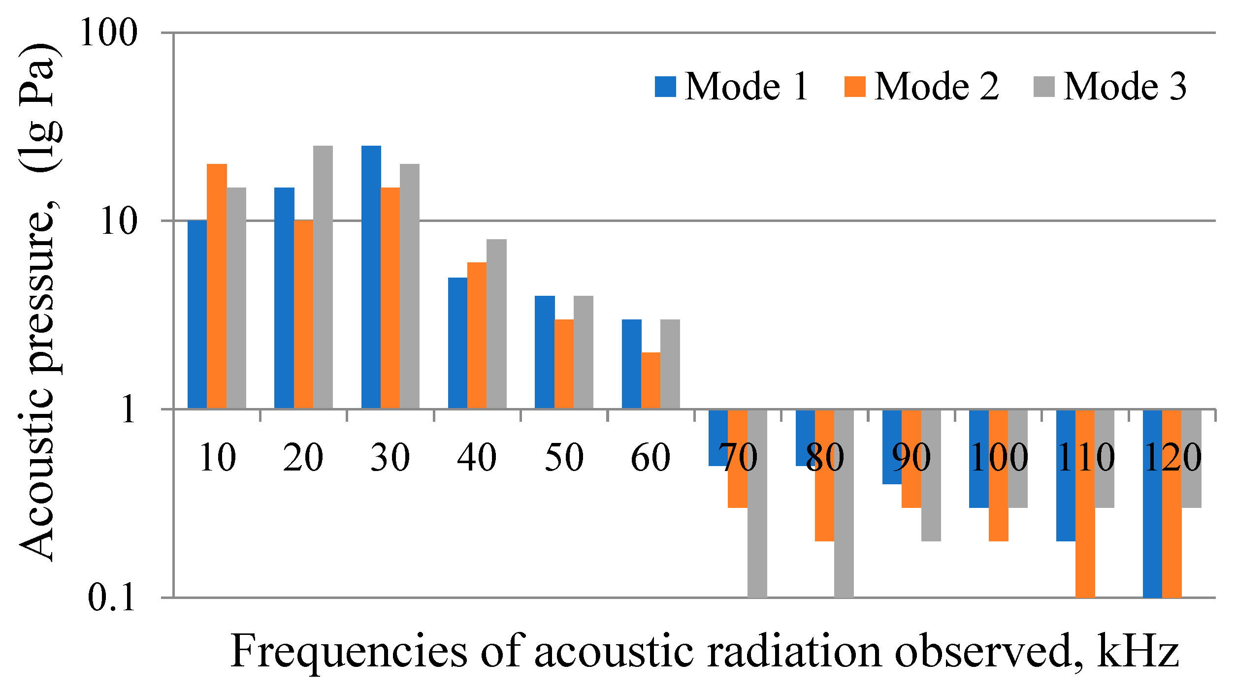
  • Previously undefined frequencies of 70–120 kHz that appear in the acoustic radiation spectrum of underwater electric discharge in cavitation mode have been revealed along with confirmed frequencies of 15–65 kHz. Thus, electric discharge in the cavitation mode generates acoustic radiation frequencies corresponding to the resonance conditions of all bubbles initially present in the working medium. Acoustic waves of such a wide frequency range ensure resonant vibration of the bubbles and strong cavitation in the treated water. The phenomena associated with cavitation ensure the inactivation of microbiological objects in the purified water.
  • It is experimentally established that the intensity of the high-frequency part of the spectrum of acoustic radiation of an electric discharge in water can be adjusted by changing the length of the uninsulated end of the electrode–anode protruding into the discharge gap and the inductance of the discharge circuit.
  • High-frequency acoustic waves generated by a special mode of electrical discharge in water and the resulting powerful volumetric cavitation are the driving force for a significant reduction in disinfectants quantity, temperature, and treatment time for water disinfection. The primary effect of electric discharge cavitation is the generation of a large number of chemically active particles and the ensuing intensification of oxidation processes. This replaces most of the active chlorine required for disinfection with active particles formed from the water medium itself; these active particles are effective but are less hazardous to the environment. Other factors of electrical discharge in the cavitation mode are of secondary importance: local shock waves, acoustic flows and turbulence, flotation effects, and rectified diffusion.
  • The similarity of the effect of ultrasound and electrical discharge in cavitation mode on water systems is demonstrated experimentally. Underwater electrical discharge as a source of cavitation does not have such intrinsic limitations as the erosion resistance of the ultrasonic emitters. At the same time, cavitation does not interfere with any stage of the discharge. In addition, both the intensity and the total power of cavitation processes induced by underwater electrical discharges are always higher compared to ultrasonic treatment due to the wider range of acoustic frequencies generated. As a result, the possibilities for industrial application of water disinfection by electrical discharge in the cavitation mode are much wider than in the case of ultrasonic treatment. This is crucial for the practical use of underwater electrical discharge not only to accelerate oxidation, but also to intensify other chemical engineering processes.

Author Contributions

Conceptualization, A.P.M., P.K., O.M., A.Y. and A.M.; methodology, A.P.M., O.M., A.Y. and A.M.; software, A.P.M., P.K., O.M., A.Y. and A.M.; validation, A.P.M., P.K., O.M., A.Y., A.M., D.P. and M.M.Z.; formal analysis, A.P.M., O.M., A.Y. and A.M.; investigation, A.P.M., O.M., A.Y. and A.M.; resources, A.P.M., P.K., O.M., A.Y., A.M., D.P. and M.M.Z.; data curation, A.P.M., O.M., A.Y. and A.M.; writing—original draft preparation, A.P.M., P.K., O.M., A.Y., A.M., D.P. and M.M.Z.; writing—review and editing, A.P.M., P.K., O.M., A.Y., A.M., D.P. and M.M.Z.; visualization, A.P.M., O.M., A.Y. and A.M.; supervision, A.P.M., P.K., O.M., A.Y., A.M., D.P. and M.M.Z.; project administration, A.P.M., P.K., O.M., A.Y., A.M., D.P. and M.M.Z.; funding acquisition, A.P.M., P.K., D.P. and M.M.Z. All authors have read and agreed to the published version of the manuscript.

Funding

Subsidy for the development and maintenance of research potential, for the discipline of environmental engineering, mining and energy, funded by the Ministry of Science and Higher Education, funding number PB29.BO.24.001—Environmental engineering, mining and energy; funding for 2024.

Data Availability Statement

The data presented in this study are available on request from the corresponding author due to privacy policy at the National Academy of Sciences of Ukraine under martial law.

Conflicts of Interest

The authors declare no conflicts of interest. The funders had no role in the design of the study; in the collection, analyses, or interpretation of data; in the writing of the manuscript; or in the decision to publish the results.

References

  1. Bezsonov, Y.; Mitryasova, O.; Smyrnov, V.; Smyrnova, S. Influence of the South-Ukraine electric power producing complex on the ecological condition of the Southern Bug River. East.-Eur. J. Enterp. Technol. 2017, 4, 20–28. [Google Scholar] [CrossRef]
  2. Bernatska, N.; Dzhumelia, E.; Dyakiv, V.; Mitryasova, O.; Salamon, I. Web-Based Information and Analytical Monitoring System Tools–Online Visualization and Analysis of Surface Water Quality of Mining and Chemical Enterprises. Ecol. Eng. Environ. Technol. 2023, 24, 99–108. [Google Scholar] [CrossRef]
  3. Mitryasova, O.; Pohrebennyk, V.; Salamon, I.; Oleksiuk, A.; Mats, A. Temporal Patterns of Quality Surface Water Changes. J. Ecol. Eng. 2021, 22, 283–295. [Google Scholar]
  4. Mitryasova, O.; Pohrebennyk, V. Hydrochemical Indicators of Water System Analysis as Factors of the Environmental Quality State. In Sustainable Production: Novel Trends in Energy, Environment and Material Systems. Studies in Systems, Decision, and Control; Królczyk, G., Wzorek, M., Król, A., Kochan, O., Su, J., Kacprzyk, J., Eds.; Springer: Cham, Switzerland, 2020; Volume 198, pp. 91–104. [Google Scholar] [CrossRef]
  5. Smyrnov, V.; Mitryasova, O.; Salamon, I.; Smyrnova, S.; Chvyr, V.; Mats, A. The Distribution of Heavy Metals Mobile Forms in the Industrial Urban Agglomeration Soil. J. Ecol. Eng. 2013, 24, 317–327. [Google Scholar]
  6. Ponnusami, A.B.; Sinha, S.; Ashokan, H.; Paul, M.V.; Hariharan, S.P.; Arun, J.; Gopinath, K.P.; Le, Q.H.; Pugazhendhi, A. Advanced oxidation process (AOP) combined biological process for wastewater treatment: A review on advancements, feasibility and practicability of combined techniques. Environ. Res. 2023, 237, 116944. [Google Scholar] [CrossRef]
  7. Zver, M.; Dobnik, D.; Zaplotnik, R.; Mozetič, M.; Filipić, A.; Primc, G. Non-thermal plasma inactivation of viruses in water solutions. J. Water Process Eng. 2023, 53, 103839. [Google Scholar] [CrossRef]
  8. Olsińska, U. Characteristics of bromate formation prevention methods in water intended for human consumption. Environ. Prot. 2017, 39, 17–26. [Google Scholar]
  9. Huang, Y.; Zhang, H.; Zamyadi, A.; Andrews, S.; Hofmann, R. Predicted impact of aeration on toxicity from trihalomethanes and other disinfection byproducts. J.—Am. Water Work. Assoc. 2017, 109, 13–21. [Google Scholar] [CrossRef]
  10. Selbes, M.; Brown, J.; Lauderdale, C.; Karanfil, T. Removal of selected C- and N-DBP precursors in biologically active filters. J. —Am. Water Work. Assoc. 2017, 109, E73–E84. [Google Scholar] [CrossRef]
  11. Wang, Q.; Yang, Z.; Ma, J.; Wang, J.; Wang, L.; Guo, M. Study on the mechanism of cerium oxide catalytic ozonation for controlling the formation of bromate in drinking water. Desalination Water Treat. 2016, 57, 15533–15546. [Google Scholar] [CrossRef]
  12. WHO. Bromine as a Drinking-water Disinfectant; WHO: Geneva, Switzerland, 2018.
  13. Dymaczewski, Z.; Jeż-Walkowiak, J.; Michałkiewicz, M.; Sozański, M.M. The importance of the disinfection process in ensuring the microbiological safety of water intended for human consumption. Environ. Prot. 2019, 41, 1. [Google Scholar]
  14. Fisher, I.; Kastl, G.; Sathasivan, A. New model of chlorine-wall reaction for simulating chlorine concentration in drinking water distribution systems. Water Res. 2017, 125, 427–437. [Google Scholar] [CrossRef]
  15. Gelete, G.; Gokcekus, H.; Ozsahin, D.U.; Uzun, B.; Gichamo, T. Evaluating disinfection techniques of water treatment. Desalination Water Treat. 2020, 177, 408–415. [Google Scholar] [CrossRef]
  16. Foster, J.E. Plasma-based water purification: Challenges and prospects for the future. Phys. Plasmas. 2017, 24, 055501. [Google Scholar] [CrossRef]
  17. Malyushevskaya, A.; Koszelnik, P.; Yushchishina, A.; Mitryasova, O.; Mats, A.; Gruca-Rokosz, R. Eco-Friendly Principles on the Extraction of Humic Acids Intensification from Biosubstrates. J. Ecol. Eng. 2023, 24, 317–327. [Google Scholar] [CrossRef]
  18. Malyushevskaya, A.P. Properties of starch size treated by an electric discharge in the mode of nonlinear volume cavitation. Surf. Eng. Appl. Electrochem. 2011, 47, 555–557. [Google Scholar] [CrossRef]
  19. Malyushevskaya, A.P.; Malyushevskii, P.P. A novel method to control electrical-discharge nonlinear bulk cavitation. Surf. Eng. Appl. Electrochem. 2007, 43, 59–64. [Google Scholar] [CrossRef]
  20. Song, K.; Liu, Y.; Umar, A.; Ma, H.; Wang, H. Ultrasonic cavitation: Tackling organic pollutants in wastewater. Chemosphere 2024, 350, 141024. [Google Scholar] [CrossRef]
  21. Zeghioud, H.; Nguyen-Tri, P.; Khezami, L.; Amrane, A.; Assadi, A.A. Review on discharge Plasma for water treatment: Mechanism, reactor geometries, active species and combined processes. J. Water Process Eng. 2020, 38, 101664. [Google Scholar] [CrossRef]
  22. Malyushevskaya, A.P.; Koszelnik, P.; Yushchishina, A.; Mitryasova, O.; Mats, A.; Gruca-Rokosz, R. Synergy Effect during Water Treatment by Electric Discharge and Chlorination. Environments 2023, 10, 93. [Google Scholar] [CrossRef]
  23. Akdoğan, E.; Şirin, H.T. Plasma surface modification strategies for the preparation of antibacterial biomaterials: A review of the recent literature. Mater. Sci. Eng. C 2021, 131, 112474. [Google Scholar] [CrossRef]
  24. Wu, U.; Nyborg, W.L. Ultrasound, cavitation bubbles and their interaction with cells. Adv. Drug Deliv. Rev. 2008, 60, 1103–1116. [Google Scholar] [CrossRef] [PubMed]
  25. Lauterborn, W.; Mettin, R. 3-Acoustic Cavitation: Bubble Dynamics in High-Power Ultrasonic Fields; Gallego-Juárez, J.A., Graff, K.F., Ultrasonics, P., Eds.; Woodhead Publishing: Sawston, UK, 2015; pp. 37–78. [Google Scholar] [CrossRef]
  26. Malyushevskaya, A.P.; Malyushevskij, P.P.; Levda, V.I. Electroexplosive nonlinear, volumetric cavitation in technological reactors. Part I (Electrodischarge generation of a gas phase—Nucleus of cavitation). Electron. Process. Mater. 2004, 40, 46–53. [Google Scholar]
  27. Malyushevskaya, A.P.; Kataev, N.M.; Malyushevsky, P.P. Ustanovlenye akustycheskykh kharakterystyk podvodnykh elektrycheskykh razriadov y sredy. Elektronnaia obrabotka materyalov [Establishing the acoustic characteristics of underwater electrical discharges in environments]. Electron. Mater. Process. 1999, 6, 33–36. [Google Scholar]
  28. Islam, M.H.; Pollet, B.G. Chapter 15—Acoustic cavitation and sonochemistry in industry: State of the art. In Energy Aspects of Acoustic Cavitation and Sonochemistry; Hamdaoui, O., Kerboua, K., Eds.; Elsevier: Amsterdam, The Netherlands, 2022; pp. 265–279. [Google Scholar] [CrossRef]
  29. Vargel, C. Chapter C.11—Erosion and cavitation. In Corrosion of Aluminium, 2nd ed.; Vargel, C., Ed.; Elsevier: Amsterdam, The Netherlands, 2020; pp. 283–288. [Google Scholar] [CrossRef]
  30. Grigoriev, B.A.; GerasimovA, A.; Alexandrov, I.S.; Nemzer, B.V. Chapter 5—Fundamental equations of state of individual substances. In Thermophysical Properties of Individual Hydrocarbons of Petroleum and Natural Gases; Grigoriev, B.A., Gerasimov, A.A., Alexandrov, I.S., Nemzer, B.V., Eds.; Gulf Professional Publishing: Oxford, UK, 2022; pp. 335–395. [Google Scholar] [CrossRef]
  31. Zhou, Y. Turbulence theories and statistical closure approaches. Phys. Rep. 2021, 935, 1–117. [Google Scholar] [CrossRef]
  32. Bulatovic, S.M. 6—Summary of the Theoretical Aspects of Flotation. In Handbook of Flotation Reagents; Bulatovic, S.M., Ed.; Elsevier: Amsterdam, The Netherlands, 2007; pp. 87–124. [Google Scholar] [CrossRef]
  33. Crum, L.A. Acoustic cavitation series: Part five rectified diffusion. Ultrasonics 1984, 22, 215–223. [Google Scholar] [CrossRef]
  34. Frommelt, T.; Schneider, M.; Wixforth, A. 8—Acoustic Methods for Manipulating Droplets. In Micro and Nano Technologies; Berthier, J., Ed.; William Andrew Publishing: Norwich, NY, USA, 2008; pp. 353–388. [Google Scholar] [CrossRef]
  35. Blake, W.K. Chapter 1—Hydrodynamically Induced Cavitation and Bubble Noise. In Mechanics of Flow-Induced Sound and Vibration, 2nd ed.; Blake, W.K., Ed.; Academic Press: Cambridge, MA, USA, 2017; pp. 1–80. [Google Scholar] [CrossRef]
  36. Hegedűs, F.; Kalmár, C.; Turányi, T.; Gy, I.; Papp, Z. Chapter 4—Sonochemical reactions, when, where and how: Modelling approach. In Energy Aspects of Acoustic Cavitation and Sonochemistry; Hamdaoui, O., Kerboua, K., Eds.; Elsevier: Amsterdam, The Netherlands, 2022; pp. 49–77. [Google Scholar] [CrossRef]
  37. Gogate, P.R. Cavitation in Biotechnology. In Comprehensive Biotechnology, 2nd ed.; Moo-Young, M., Ed.; Academic Press: Cambridge, MA, USA, 2011; pp. 957–965. [Google Scholar] [CrossRef]
  38. Ming, L.; Zhi, N.; Chunhua, S. Numerical simulation of cavitation bubble collapse within a droplet. Comput. Fluids 2007, 152, 157–163. [Google Scholar] [CrossRef]
  39. Hanafi, M.F.; Sapawe, N. A review on the current techniques and technologies of organic pollutants removal from water/wastewater. Mater. Today Proc. 2020, 31, A158–A165. [Google Scholar] [CrossRef]
  40. Agarkoti, C.; Gogate, P.R.; Pandit, A.B. Coupling of acoustic/hydrodynamic cavitation with ozone (O3), hydrogen peroxide (H2O2), magnesium oxide (MgO) and manganese dioxide (MnO2) for the effective treatment of CETP effluent. Sep. Purif. Technol. 2022, 284, 120281. [Google Scholar] [CrossRef]
  41. Dehane, A.; Merouani, S.; Hamdaoui, O. Effect of carbon tetrachloride (CCl4) sonochemistry on the size of active bubbles for the production of reactive oxygen and chlorine species in acoustic cavitation field. Chem. Eng. J. 2021, 426, 130251. [Google Scholar] [CrossRef]
  42. Liu, S.; Yuan, X.; Shao, Z.; Xiang, K.; Huang, W.; Tian, H.; Huang, Y. Investigation of singlet oxygen and superoxide radical produced from vortex-based hydrodynamic cavitation: Mechanism and its relation to cavitation intensity. Sci. Total Environ. 2024, 929, 172761. [Google Scholar] [CrossRef] [PubMed]
  43. Rooze, J.; Rebrov, E.V.; Schouten, J.C.; Keurentjes, J.T.F. Dissolved gas and ultrasonic cavitation—A review. Ultrason. Sonochemistry 2013, 20, 1–11. [Google Scholar] [CrossRef] [PubMed]
  44. Yushchyshyna, A.N.; Maliushevskii, P.P.; Smalko, A.A.; Petrichenko, L.A.; Tyhonenko, S.M. Iodometric determination of electric discharge volume cavitation. Electron. Process. Mater. 2002, 2, 76–80. [Google Scholar]
  45. Gągol, M.; Soltani, R.D.C.; Przyjazny, A.; Boczkaj, G. Effective degradation of sulfide ions and organic sulfides in cavitation-based advanced oxidation processes (AOPs). Ultrason. Sonochemistry 2019, 58, 104610. [Google Scholar] [CrossRef] [PubMed]
  46. Ji, H.; Lan, Y.; Nie, S.; Qin, T.; Nie, S.; Zhou, J. Synergistic effect of hydrodynamic cavitation characteristics of self-excited oscillation cavity for degradation of dye wastewater. J. Clean. Prod. 2022, 380, 135116. [Google Scholar] [CrossRef]
  47. Kudo, K.; Ito, H.; Ihara, S.; Terato, H. Quantitative analysis of oxidative DNA damage induced by high-voltage pulsed discharge with cavitation. J. Electrost. 2015, 73, 131–139. [Google Scholar] [CrossRef]
  48. Fuciarelli, A.F.; Sisk, E.C.; Thomas, R.M.; Miller, D.L. Induction of base damage in DNA solutions by ultrasonic cavitation. Free Radic. Biol. Med. 1995, 18, 231–238. [Google Scholar] [CrossRef]
  49. Kamal, H.; Ali, A.; Manickam, S.; Le, C.F. Impact of cavitation on the structure and functional quality of extracted protein from food sources—An overview. Food Chem. 2023, 407, 135071. [Google Scholar] [CrossRef]
Figure 1. Laboratory electric discharge installation [22].
Processes 12 01846 g001
Figure 2. Histograms of acoustic radiation of the underwater electric discharge (post-discharge stage).
Processes 12 01846 g002
Table 1. The amplitude–time characteristics of the current pulses generated (energy stored in a single pulse 78.125 J, with a capacitance of 0.25 μF).
Mode No.Length of the Uninsulated End of the Anode, mmDischarge Circuit Inductance, μHCurrent Pulse Period, μsDuration of Current First Half-Wave, μsDuration of the Leading Edge of the Current Pulse, μsCurrent Pulse Amplitude, kA
141.25.42.71.3516
2101.26.53.251.6212
372.69.04.51.814
Table 2. Results of electro-discharge treatment of contaminated water (initial concentration of E. coli: 1·106 CFU/dm3).
Specific Energy of Discharge Treatment (Cavitation Mode), kJ/dm3E. coli Concentration after Treatment, (lg CFU/dm3)
Additional Chemical Agent
Cl, 1 mg/dm3Cl, 0.8 mg/dm3Cl, 0.6 mg/dm3Cl, 0.4 mg/dm3Cl, 0.2 mg/dm3
544.34.655.2
1512.533.23.4
2500000.5
Table 3. Typical parameters of electric discharge cavitation [26].
Initial Bubble Radius, R0, mMaximum Bubble Radius, Rmax, mMinimum Bubble Radius Rmin, mGas Content, δPressure Developed When the Bubble Collapses pmax, PaRatio of the Sound Speed in the Medium to the Velocity of the Leading Edge of the Microcavitation Wave
1·10−32.9·10−35.8·10−54.8·10−27.4·1034.5
5·10−42.6·10−32.5·10−51.0·10−21.9·1046.2
1·10−42.3·10−30.9·10−62.1·10−42.8·10713.3
Disclaimer/Publisher’s Note: The statements, opinions and data contained in all publications are solely those of the individual author(s) and contributor(s) and not of MDPI and/or the editor(s). MDPI and/or the editor(s) disclaim responsibility for any injury to people or property resulting from any ideas, methods, instructions or products referred to in the content.

