Article

A Numerical Study on Key Thermal Parameters and NOx Emissions of a Hydrogen-Fueled Double-Channel Outlet Micro Cylindrical Combustor Employing a Heat-Recirculating Configuration for Thermophotovoltaic Applications

Department of Mechanical Engineering, College of Engineering, King Faisal University, Al-Ahsa 36362, Saudi Arabia
Processes 2024, 12(9), 1848; https://doi.org/10.3390/pr12091848
Submission received: 1 August 2024 / Revised: 21 August 2024 / Accepted: 29 August 2024 / Published: 29 August 2024
(This article belongs to the Special Issue Combustion Process and Emission Control of Alternative Fuels)

Abstract

:
The current study proposes a novel design configuration of a hydrogen-fueled micro cylindrical combustor. The newly developed design consists of a single-channel inlet and a double-channel outlet with a heat-recirculating structure aimed at enhancing the heat transfer mechanism from the combustion to the walls. Investigations are conducted using three-dimensional numerical simulation means, and emphasis is placed on assessing the effects of the novel design structure on key thermal parameters and nitrogen oxide (NOx) emissions. The numerical modeling approach is first validated against the experimental and numerical data available in the literature. A parametric study is then conducted by means of varying the length and width of the heat-recirculating channel, inlet velocity, and inlet equivalence ratio. The findings revealed that the novel design configuration significantly improves thermal performance and curtails NOx emissions in comparison with those of the conventional structure. For example, the proposed design leads the radiation efficiency to increase by roughly 10%. The increase in the width of the preheating channel yields further optimization by boosting the heat transfer process from the flame to the walls. Elevating the inlet velocity exhibits a pronounced increase in the mean wall temperature and a more uniform distribution of the wall temperature. However, the exhaust gas temperature increases with increasing inlet velocity, leading to a reduction in the exergy and radiation efficiencies. The equivalence ratio of unity optimizes key thermal parameters, as the lean and rich conditions suffer from low hydrogen and oxygen contents, respectively.

1. Introduction

Combustion systems are mainly powered either by coal or other fossil fuels, which leads to an increase in the consumption rates of such essential, unsustainable energy sources. In addition, the combustion of hydrocarbon fuels produces the carbon-based emissions NOx and SOx [1,2] and, consequently, causes global warming and other environmental issues, such as declining air quality [3,4]. In 2018, it was found that the percentage of electricity generated from fossil fuels reached 61%, whereas 29% and 10% came from renewable and nuclear sources of energy, respectively [5]. Thus, the energy transition from conventional to renewable fuels has become paramount for enacting steep carbon emission cuts and reducing the depletion rate of fossil fuels.
Hydrogen is a high-performance, carbon-free fuel [6,7] and has the potential to replace conventional fossil fuels within the industrial sector [8], thereby facilitating the transition towards sustainable energy systems. The utilization of hydrogen energy as an alternative source can yield noteworthy reductions in carbon emissions and air pollution [9], while concurrently diminishing reliance on finite resources [10]. Hydrogen also enhances performance and combustion characteristics due to its high diffusion rate and flame speed [11]. However, NOx emissions represent one of the biggest disadvantages of hydrogen combustion. The formation of such a harmful pollutant can be attributed to three main mechanisms. The first is thermal NOx, in which NOx is produced by a set of greatly temperature-dependent oxidizations of the nitrogen—known as the extended Zeldovich mechanism—that is present in the combustion air. Prompt NOx is the second, and NOx is formed in this mechanism by high-speed chemical reactions between nitrogen and the combustion products at the flame front. The third mechanism is fuel NOx, in which NOx is formed by means of an oxidation of nitrogen bonded in the fuel. Detailed explanations of these mechanisms can be found in [12,13].
Micro-scale combustors have drawn attention for thermal power generation applications [14,15] owing to their small size, reliability, energy intensity, and long working time [16,17,18]. On a small scale, the energy produced by micro-combustors is found to be significantly higher than that of conventional batteries [19]. Micro thermophotovoltaic (MTPV) technology is a micro machining application that has advantages over its counterparts because it has no moving parts and is therefore easy to manufacture and assemble [20]. In MTPV applications, fuel combustion produces thermal energy in the micro-combustor, which is then transferred to the PV cells through a filter to generate electricity. The most important parameter to consider in this process is the emitter efficiency of the micro combustor, as it is a measure of output power density and energy conversion efficiency. The emitter efficiency, in turn, depends on the external wall temperature and its distribution along the external wall of the micro combustor.
Different techniques have been employed for MTPV systems aimed at enhancing wall temperature and its uniformity over the outer surface. Peng et al. [21] investigated the effects of inserting ten types of porous medium (PM) with varying wire diameters and pores per inch on H2/C3H8-air combustion in MTPV applications. The findings indicated that employing PM allows for further improvements in flame stability and heat transfer from the combustion chamber to the external wall, thus elevating electrical power output and energy conversion efficiency. Moreover, the smaller pores per inch can increase the efficiency of PM at a high flow rate, while the mean wall temperature and its distribution are enhanced with a PM areal density of 0.0524–0.0551 g/cm2 at various fuel flow rates. Wang et al. [22] conducted an investigation on the effects of a PM aperture arrangement on the combustion characteristics of a methane-fueled micro cylindrical combustor. The authors highlighted that PM is important to reasonably lay out, and the small and large pore porous media embedded in the inner and outer layers, respectively, can result in better combustion performance. Qian et al. [23] studied the effects of bluff body as a flame holder on the thermal performance of planar micro PM combustors. The results showed that the bluff body increases the system efficiency and blowout limit by 14.72% and 33%, respectively, compared to a system without such a flame holder. In addition to the highlighted studies, several techniques have been proposed in the literature for stabilizing the flame and increasing thermal efficiency, such as heat loss controlling [24] and catalyst [25].
Although different methods have been proposed for improving MTPV thermal efficiency and electrical power output, the modification of micro combustor configurations has been thoroughly investigated in recent years. It has been confirmed that an efficient structure can potentially lower the exhaust gas temperature, thereby decreasing energy loss by enhancing the heat transfer from combustion to the external walls. For example, Tang et al. [26] investigated the thermal performance of a hydrogen-fueled micro planar combustor employing parallel separating plates. The implementation of the parallel partitions improves the mean external wall temperature by 100 K more than that of a conventional micro combustor, leading to enhanced emitter efficiency. Rong et al. [27] investigated the thermal performance and NOx emission characteristics of a newly designed micro planar combustor with a reverse-flow single-channel inlet and a double-channel outlet configuration. They found that the proposed design enhances the thermal efficiency because the outer mean wall temperature is higher, and the NOx pollution is lower. Zhao et al. [28] studied the thermal performance of novel heat-recirculating micro planar combustors powered by hydrogen and ammonia. They noted that wall temperature uniformity increases considerably with the heat recirculation structure, indicating an improvement in key thermal parameters and output power. Rong et al. [29] examined the thermodynamic and emission variables of reverse flow double-channel inlet and double-channel outlet micro combustors for MTPV technology. This novel design forms a vortex at the micro combustor outlets, thus resulting in a reduction in NOx emissions and an improvement in wall temperature distribution and, accordingly, thermal performance. Cai et al. [30] conducted an investigation of NOx emissions in perforated plate micro combustors fueled by ammonia. They found that low perforated plate porosity with greater thickness can potentially minimize NOx emissions.
Numerous modifications of micro combustor configurations have been proven to enhance thermal performance and mitigate NOx emissions. However, scholars who have suggested such novel micro combustor designs have focused on the planar type of micro combustor, implying a greater margin of improvement for the micro cylindrical combustor. Since there is significant potential in conducting in-depth investigations to fill the research gap concerning cylindrical micro combustor applications fueled by a premixed hydrogen–air mixture, this work proposes a novel design configuration with a reverse flow channel, a single-channel inlet, and a double-channel outlet aiming at enhancing system efficiency and achieving better environmental performance. This numerical investigation intends to identify how the newly proposed structure affects the heat transfer process between hot gases and the outer wall along with the NOx emissions. Section 2 presents the newly designed micro cylindrical combustor. The computational work was conducted with the aid of turbulence and combustion modeling approaches, namely realizable k ϵ and species transport models, respectively. In addition, the initial and boundary conditions along with other numerical settings are provided. Mesh sensitivity analysis was performed to balance the results’ accuracy and computational cost. To prove the reliability of the simulation findings, the validation process was conducted by comparing the numerical results against the experimental and kinetic modeling data. Section 3 discusses the effects of the proposed design compared to the conventional design, the length and width of the preheating channel, the inlet velocity, and the inlet equivalence ratio. The overall summary of the main findings, as well as the conclusions derived from the investigation, are provided in Section 4.

2. Numerical Methodology

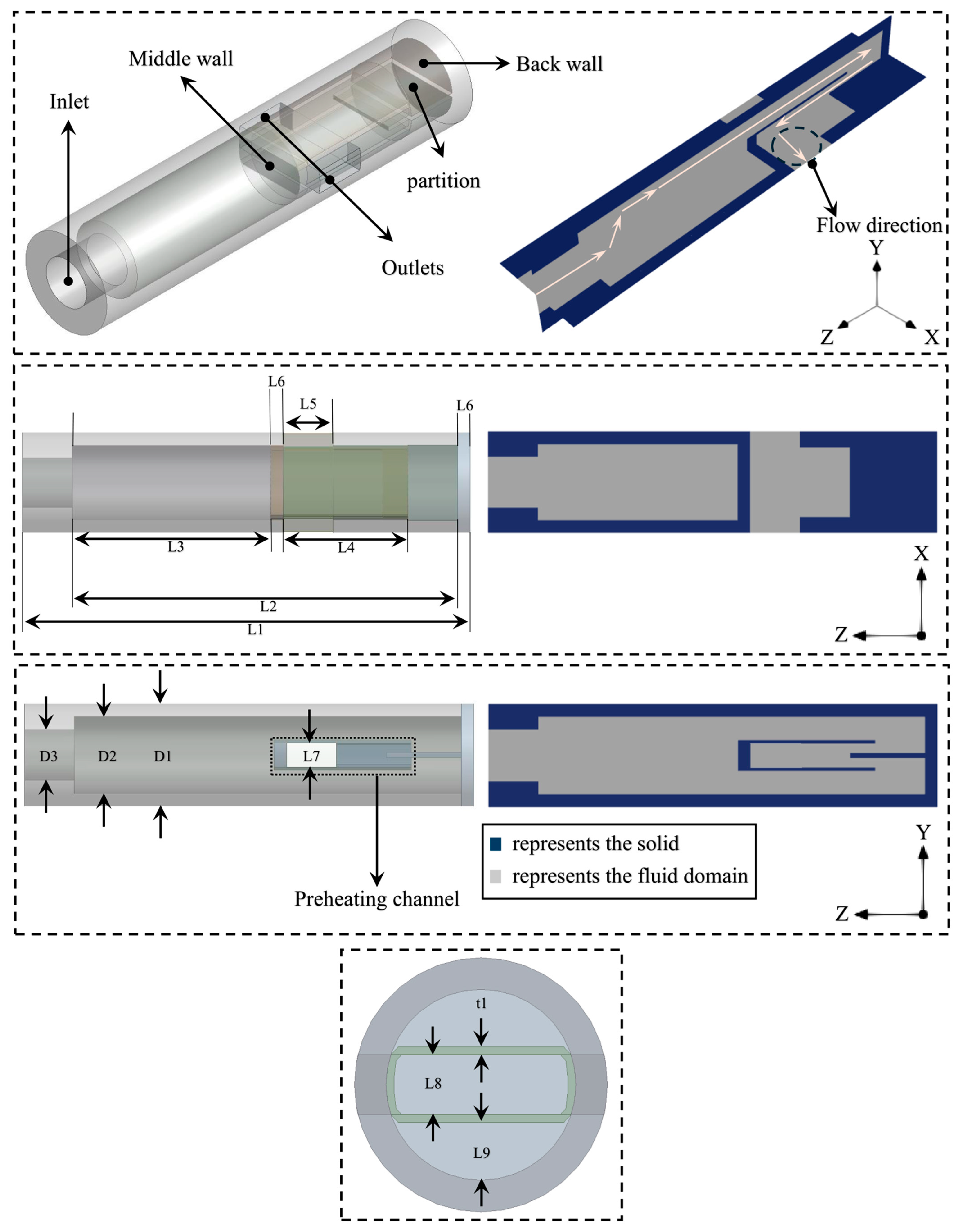
2.1. Geometric Model

The newly developed micro cylindrical combustor was designed with the aid of ANSYS Design Modeler. Its schematic representation is depicted in Figure 1 and all dimensions are provided in Table 1. The main idea behind the novel design lies in establishing the middle and back walls. The former acts as a heat holder of the high-temperature flame and, also, a flame distributor toward the outer walls to enhance the heat transfer process from the thermal energy that results from the combustion to the upper and lower external walls. The back wall recirculates the heat to the inner preheating channel, aiming to extend the blow-off limit and to increase the heat transfer capacity between the flame and the solid walls. The partition established at the end of the micro combustor is built to ensure that the hot flow enters the preheating channel.

2.2. Governing Equations

The numerical simulations were carried out using ANSYS Fluent R1 2023 [31] with the aid of King Abdullah University of Science and Technology (KAUST) high computing facilities Shaheen-III. The conservation equations solved during the simulations run-time are the mass, momentum, energy and 1-N species transport equations, where N stands for the total number of species for the chemically reacting mixture.
Mass:
· ρ v = 0
Momentum:
ρ v · v = P + · τ τ
where
τ = μ v + v T 2 3 v Ι
Energy:
· v ρ E + p = · k e f f T j h j J j + τ · v + S h
Species:
· ρ v Y i + J i = R i
In addition to the above transport equations, the sub-model of NOx emissions is enabled, meaning that one additional transport equation for the NOx mass fraction, Y N O x , is solved to account for thermal [32] and prompt [33] mechanisms.
· ρ v Y N O x = · ρ D Y N O x
where ρ is the density, v is the velocity vector, P is the static pressure, τ is the viscous stress, τ is the Reynolds stress, μ is the molecular viscosity, Ι is the unit tensor, E is the total energy of the fluid, k e f f is the effective conductivity, T is the temperature, h j is the enthalpy of species j , J j is the diffusion flux of species j , S h is the enthalpy source term of fluid, Y i is the local mass fraction of species i , J i is the diffusion flux of species i , R i is the reaction net rate of production of species i , and D is the effective diffusion coefficient.
The incorporation of surface reaction, the Dufour effect, and gravity in the simulation of micro combustion results in negligible effects [34,35,36]; thus, they were disregarded in the present investigations. Furthermore, the flow is assumed to be incompressible due to the low Mach number. However, the turbulent modeling approach is critical to incorporate in the present work, as the Reynolds number of the premixed hydrogen–air mixture at the inlet of numerical geometry exceeds 500 [37]. Therefore, the Realizable k - ϵ model [38] is employed to account for the turbulent flow properties and their effects on combustion. It is important to mention that the diffusion flux is computed by the full multicomponent diffusion approach.

2.3. Numerical Setup and Boundary Conditions

The species transport combustion modeling approach comprises different techniques to model chemistry. In this work, the eddy dissipation concept (EDC) [39,40,41] is employed to accommodate the chemistry mechanisms of 19 species and 63 chemical reactions consisting of hydrogen and NOx mechanisms [42,43]. The pressure–velocity coupling is carried out using the SIMPLE algorithm method. The spatial discretization of the governing equations and species transport equations is performed using the second-order UPWIND scheme. To ensure accuracy, the convergence criteria of all the residuals is set at 10−6. The thermal conductivity and viscosity are modeled using the ideal gas mixing law, and the specific heat is computed with the aid of the mixing law. Kinetic theory is employed to model the mass diffusivity and the incompressible ideal gas law for density. Table 2 summarizes the important parameters of the numerical modeling settings in this study.
The inlet and outlet boundary conditions are set to be the velocity inlet and pressure outlet, respectively. The gauge pressure and turbulent intensity at the inlet and outlet are 0 Pa and 5%, respectively, whereas the inlet temperature of the hydrogen–air mixture is 300 K. The material of the solid wall is steel; its thermal properties are provided in Table 3 [44]. Zero diffusive flux species along with no slip boundary conditions are applied. For the external wall of the micro combustor, the heat transfer of both the conduction and radiation is considered. The conductive heat transfer coefficient is set at 10 W/(m2·K) [45], and the outer wall emissivity is 0.85 [46,47]. The summary of the boundary conditions applied in this work is provided in Table 4.
The convection and radiation heat loss Q from outer walls is calculated as follows [48,49]:
Q = Q c o n + Q r a d   h   A c T w , i T + ε σ A c T w , i 4 T 4
where Q c o n and Q r a d donate the heat losses by convection and radiation, respectively, h stands for natural convection heat transfer coefficient (10 W/m2·K), A c the surface area of the outer wall, T w the temperature of external wall, T the ambient temperature (300 K), ε the emissivity of the solid surface (0.85), and σ the Stephan–Boltzmann constant (5.67 × 10⁻⁸ W/m2·K4).
The pressure drop of flow through the micro combustor channels results from friction and heating effects; therefore, characterizing this drop can be carried out by calculating the pressure loss P l o s s as follows [50]:
P l o s s   = P i n   P o u t  
where P i n   and P o u t   signify the pressure at the inlet and outlet, respectively.
The calculation of exergy efficiency is conducted by means of the second law of thermodynamics [51,52,53]. The inlet exergy E x i n and total exergy losses E x e g can be evaluated as:
E x i n = m ˙ f u e l   × Q L H V  
and
E x e g = E x l o s s + m ˙ i n l e t   × T × c p , o u t l e t × ln T T e g
where m ˙ f u e l   represents the mass flow rate of fuel, Q L H V   the lower heating value of fuel (119.962 MJ/kg) [4], E x l o s s the energy loss from the combustion exhaust gas, m ˙ i n l e t  the mass flow rate of inlet flow, c p , o u t l e t the specific heat capacity at the combustor outlet, and T e g exhaust gas temperature.
The uncounted exergy destruction E x d e s , which can be calculated with the aid exergy balance, and exergy efficiency η e x e r g y are computed as:
E x d e s = E x i n E x e g
and
η e x e r g y = 1 E x d e s E x i n × 100 %
The radiation efficiency is calculated as follows:
η r a d i a t i o n = Q r a d m ˙ f u e l   × Q L H V   × 100 %
The combustion efficiency η c o m b u s t i o n is computed as [54]:
η c o m b u s t i o n = 1 Y f u e l , o u t Y f u e l , i n × 100 %
where Y f u e l , i n and Y f u e l , o u t stand for the fuel mass fractions at the inlet and outlet of combustor, respectively.
The calculation of the area-weighted-mean wall temperature T w , m and wall temperature uniformity R T is performed as [55]:
T w , m = i = 1 n T i A i i = 1 n A i
and
R T = i = 1 n T i T m A i i = 1 n A i × 100 %

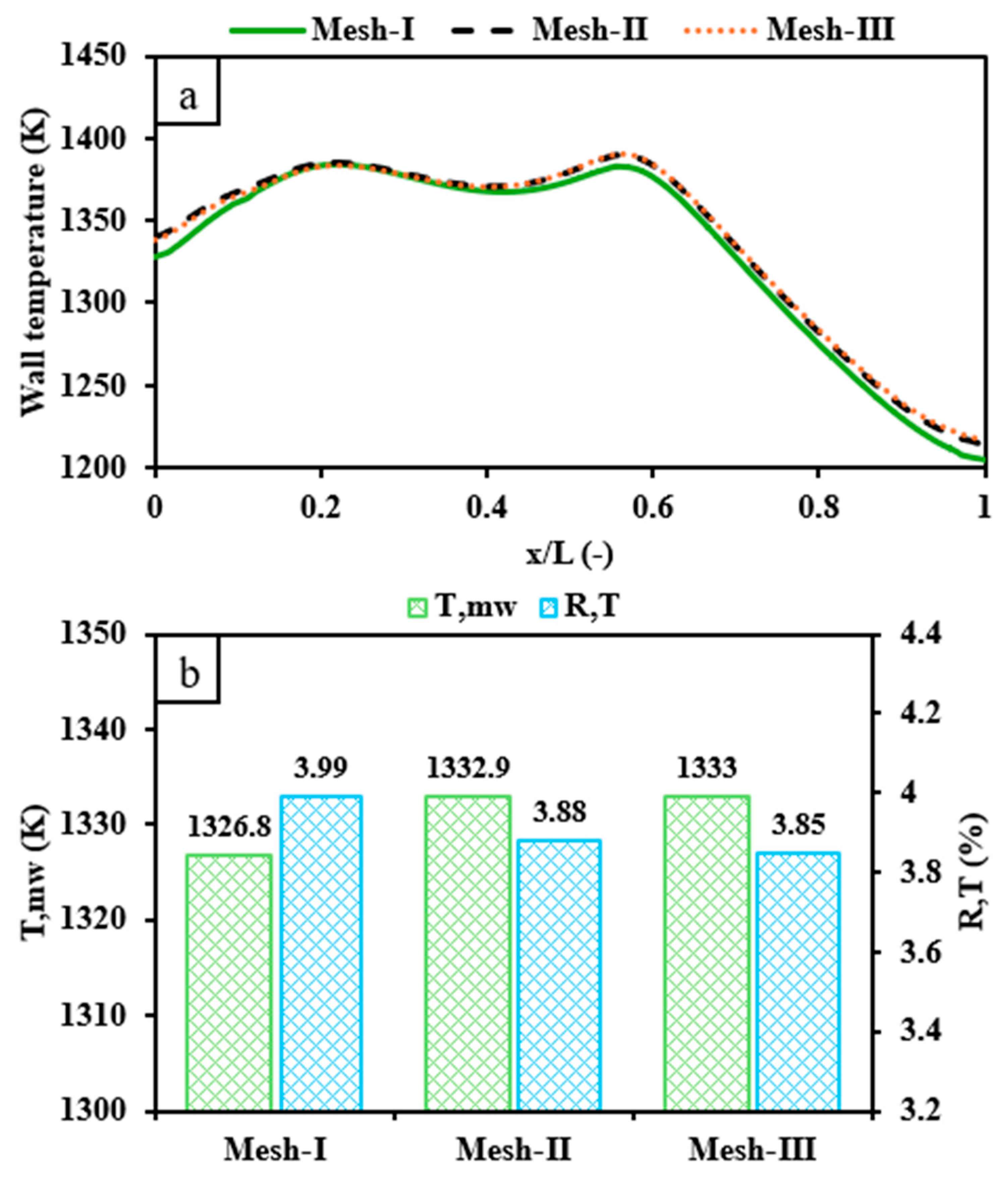
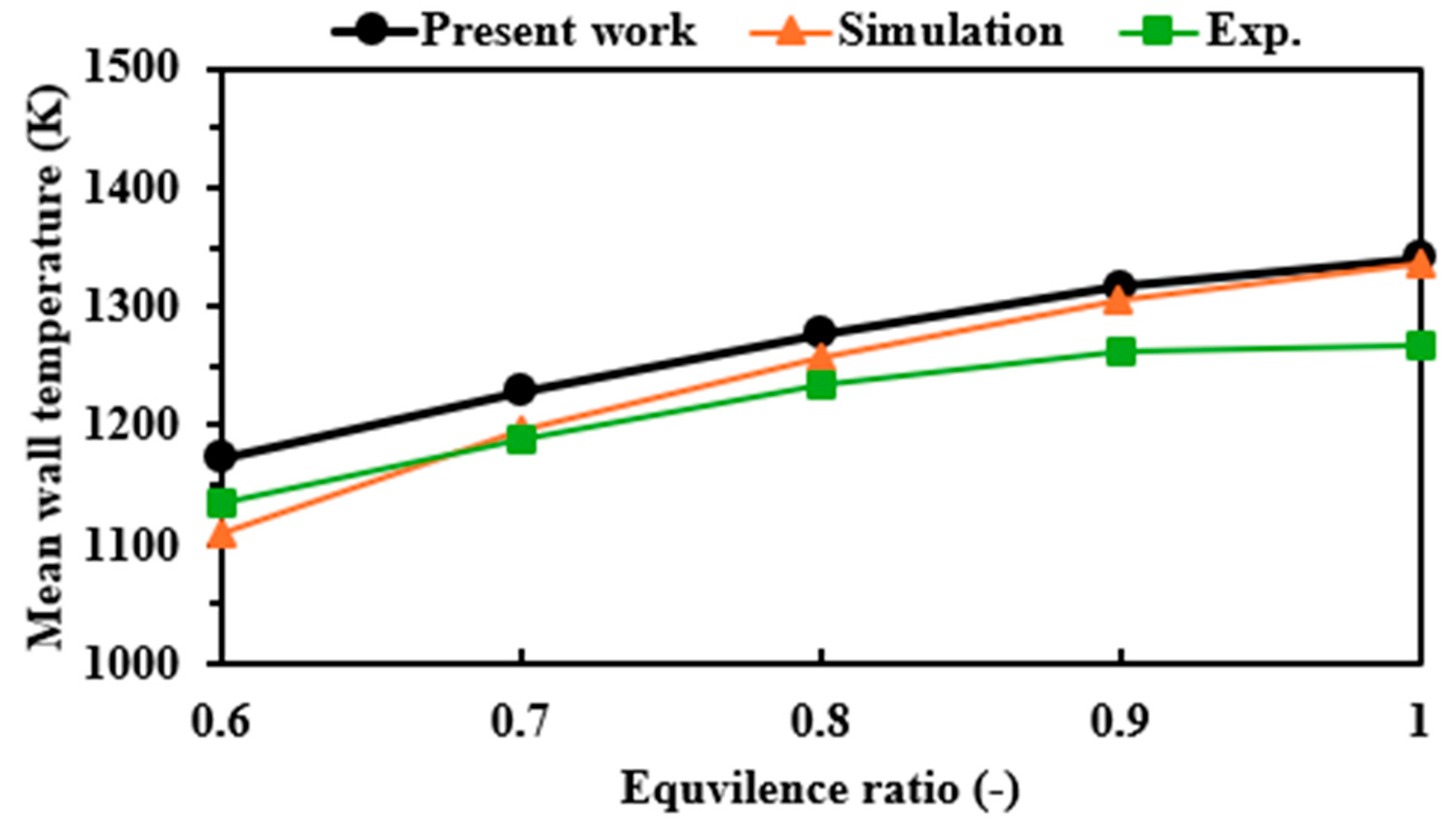
2.4. Mesh Sensitivity Analysis and Model Validation

Mesh generation is a critical step in CFD for balancing computing power and the accuracy of the numerical results. Therefore, it is important to conduct a mesh sensitivity analysis to properly select the mesh size for all subsequent simulations. The numerically predicted results in the study are produced at an equivalence ratio of 1 for the premixed hydrogen–air mixture and an inlet velocity of 8 m/s. The distance from the inlet and outlet is represented by L, and the distance from the inlet is x. The number of cells for the mesh independence test is 131,922 (Mesh-I), 451,954 (Mesh-II), and 796,770 (Mesh-III).
Figure 2 shows the comparison between the highlighted mesh resolutions in terms of wall temperature, area-weighted-mean wall temperature T w , m , and wall temperature uniformity R T . As seen in Figure 2, the numerical findings of Mesh-II are very similar to those of Mesh-III; however, the low-numbered mesh case (Mesh-I) is more conducive to lowering the computed wall temperature than the higher-numbered mesh cases. In addition, the deviations of T w , m and R T between Mesh-I (Mesh-II) and Mesh-III are roughly 0.5 K (0.01 K) and 3.6% (0.78%), respectively. Thus, the mesh of 451,954 cells (Mesh-II) is selected for the rest of the simulations as it ensures accurate predictions and reasonable computing efforts.
As the mesh independence study illustrates that the reliability of the mesh with 451,954 cells is adequate, it is important to conduct the validation process to ensure that the modeling settings are accurate and viable. Therefore, T w , m of the micro cylindrical combustor without the newly proposed design is validated against the experimental findings of Yang et al. [56] and the numerical results of Zuo et al. [57] at different equivalence ratios ranging from 0.6 to 1, as shown in Figure 3. To ensure that the comparison is performed correctly, the inlet velocity is set at 12 m/s, and silicon carbide is selected as the material of the solid wall to run the simulations under similar conditions as the highlighted experimental and numerical investigations. Figure 3 demonstrates that as the equivalence ratio increases from 0.6 to 1, the T w , m curve of the present work exhibits an increasing trend which agrees with the trends in the experimental and numerical findings. Furthermore, the maximum relative deviation between the present work and those of the experiment (simulation) is 5.79% (5.6%) at an equivalence ratio of 1 (0.6), while the corresponding average deviation is 4.04% (2.19%). These percentages of error fall within the acceptable range, thereby confirming the applicability and viability of the simulation modeling approaches and methods employed in the current work.
In the past decade, computational fluid dynamics (CFD) have been widely used to simulate different combustion applications, such as micro combustion [28,29] and the internal combustion engine [58,59]. The CFD modeling approach has proven to be one of the key research tools in terms of the development and improvement of several applications, as it ensures efficient and flexible design guidelines before cutting the metal to perform more expensive experiments. Therefore, the investigation in this paper is carried out via numerical simulation means.

3. Results

3.1. Effects of Newly Proposed Design and Preheating Channel Lengths

The potential effects of the newly developed structure of the micro cylindrical combustor and the preheating channel lengths on key thermal parameters and NOx emissions are discussed in this sub-section. The test cases investigated here are C1, C2, C3, and C4, and the configuration dimensions are provided in Table 1. C1 represents the conventional micro combustor. This parametric study is conducted to optimize the new design and to demonstrate how it potentially affects system efficiency and environmental variables. For all cases, the inlet velocity is set to 8 m/s, while the inlet equivalence ratio is maintained at 1.
Figure 4a presents the effects of the novel structure of the heat recirculating micro combustor compared to the conventional one along with the effects of the various lengths of the preheating channel on the distribution of the wall temperature. In all cases, the new design configuration demonstrates a significant increase in wall temperature, as the temperature distribution of C2, C3, and C4 over the external combustor walls is notably greater than that of C1, indicating an increase in the heat absorption capacity of the solid walls. This improvement is caused by the presence of the middle wall, as it is conducive to holding the high-temperature flame and distributing it to the walls, consequently improving the heat transfer mechanisms from the flame to the wall. In addition, the back wall reverses the hot gases into the heat recirculating channel for preheating purposes instead of rejecting them toward the surroundings. Figure 4a illustrates that the various lengths of the preheating channel lead to fluctuating behavior in terms of the maximum and minimum wall temperatures. The numerically predicted findings indicate that increasing the length of the preheating channel tends to greatly promote the increasing rate of the wall temperature, followed by a rate that falls off sharply, as C4 (the highest preheating channel length) achieves the maximum and minimum wall temperatures when compared to C2 and C3. This could be attributed to the optimal position of the middle wall, because the closest middle wall to the inlet (C4) seems to suppress the free propagation flame of hydrogen, which results in a sharp decrease in the back wall region.
Figure 4b depicts the variation in the mean wall temperature T w , m and the wall temperature uniformity R T for C1, C2, C3, and C4. It reveals that the proposed design leads to the potential escalation of T w , m , as C1 is lower than C2, C3, and C4 by 63.4, 60.2, and 53.7 K, respectively. Surprisingly, Figure 4b shows that C1 achieves a more uniform wall temperature than C3 and C4 but less uniformity than C2. This fluctuating trend could be caused by the ideal location of the middle wall, because hydrogen is characterized by a high flame speed and therefore requires a greater volume to propagate freely to then maximize the benefits from its high energy content. In general, the variation in T w , m and R T indicates that C2 is optimal for improving the wall temperature’s key parameters. It is noteworthy that the high wall temperature may result in a decrease in the structural strength of the wall materials. Therefore, thermal barrier coatings or ceramic material are important to consider in the wall manufacturing process in order to withstand the high temperature.
Figure 5 illustrates the variations in temperature and OH mass fraction throughout the combustion chamber under different preheating channel lengths of the micro cylinder combustor. Figure 5a displays that the high-temperature flame of C1 tends to narrow toward the outlet; however, the presence of the preheating channel in C2, C3, and C4 exhibits an effective means of widening the area of high temperature to be near the walls at the middle wall positions. Furthermore, as the middle wall prevents the free propagation of flame in the center of the micro combustor domain, it is then propagated in the volumetric space between the inner channel and external walls. This enhances the wall temperature distribution and confirms the findings shown in Figure 4. Furthermore, this improvement is enhanced as the heat-recirculating channel is shorter, highlighting the importance of allowing the hydrogen flame to propagate freely in a larger space. The distribution of OH radicals is depicted in Figure 5b and behaved similarly to the temperature distribution. It is noteworthy that employing the preheating channel appears to widen the OH variations, thus indicating a more intense and vigorous chemical reactivity closer to the outer walls.
Figure 6 shows the effects of the micro combustor configurations on NOx emissions and exhaust gas temperature. The variations in NOx pollution highlight that the newly designed combustor greatly decreases such harmful emissions by improving the heat absorption coefficient of the walls and, additionally, recirculating the high-temperature flow for preheating purposes instead of releasing it into the atmosphere. These effects lead the average exhaust gas temperature to decrease, which indicates that lower thermal energy is wasted from the system. However, decreasing the length of the heat-recirculating channel results in further optimization, as the NOx emissions and average exhaust gas temperature are reduced when the inner channel changes from long (C4) to short (C2). This highlights that the thermal performance is promoted by the preheating channel, and, moreover, the shorter channel is beneficial for further improvements in the heat transfer process.
The discrepancies in exergy, radiation, and combustion efficiencies, and the pressure drop with respect to various micro combustor configurations, are shown in Figure 7. As depicted in Figure 7a, the presence of the preheating channel tends to improve the exergy efficiency, as the efficiency of the conventional micro combustor (C1) is lower than that of the newly designed ones (C2, C3, and C4) due to the high exhaust gas temperature of the former. Similarly, Figure 7a indicates that radiation efficiency is greatly enhanced by the preheating channel, as the differences between C1 and C2, C3, and C4 are 9.9%, 9.4%, and 9.1%, respectively, confirming the potential of the newly proposed design to enhance system performance. However, the variation in inner channel lengths tends not to greatly affect the system efficiency as the exergy and radiation efficiencies of C2, C3, and C4 are highly comparable. Figure 7b demonstrates that the majority of the fuel is consumed for all test cases because their combustion efficiencies are mostly the same. However, employing the preheating channel (C2, C3, and C4) notably increases the pressure drop in comparison to the case without this channel (C1). This suggests that the presence of the middle and back walls forms barriers in front of the premixed charge flowing from the inlet, which implies that the newly proposed design requires more pumping power.

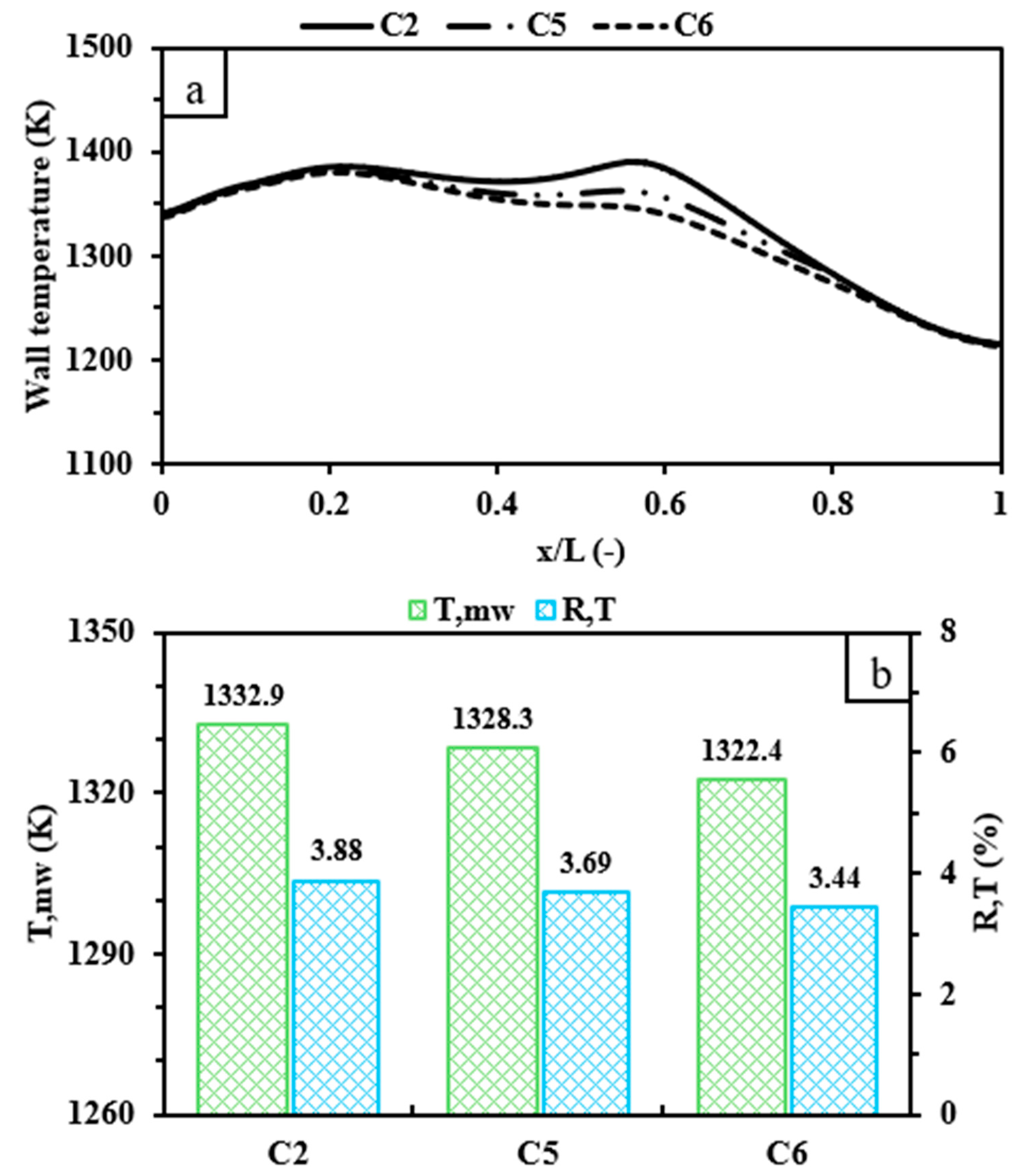
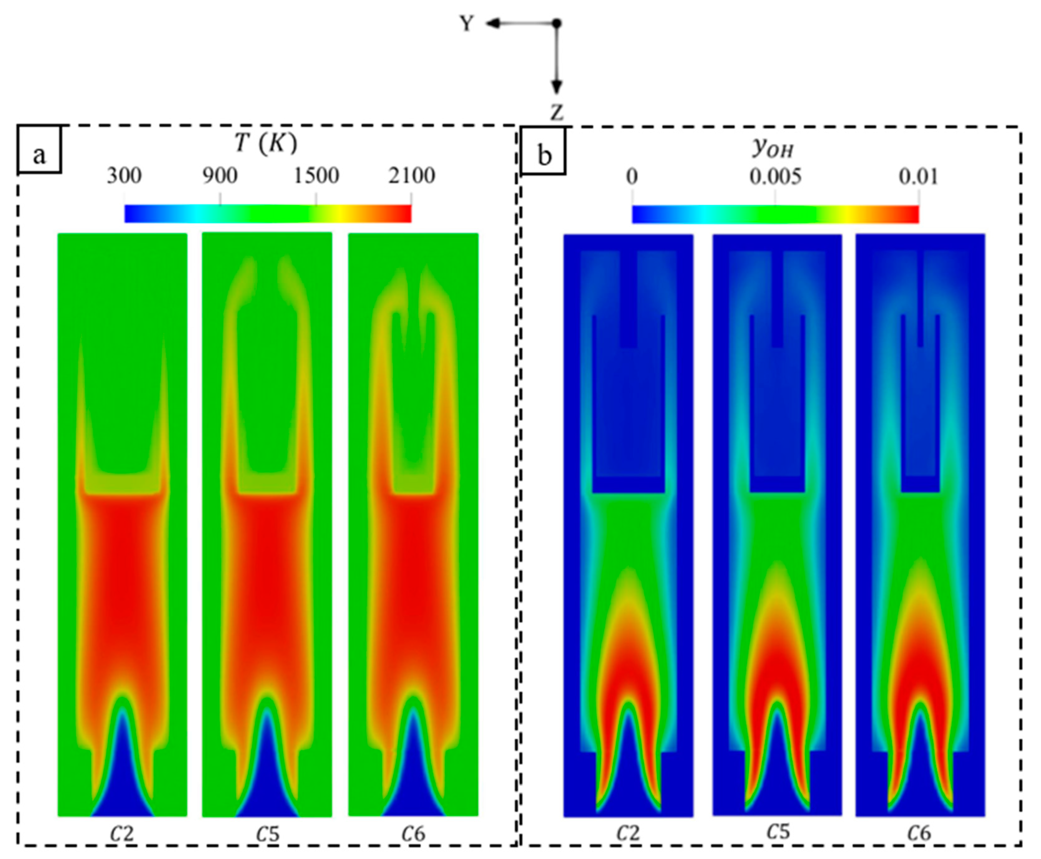
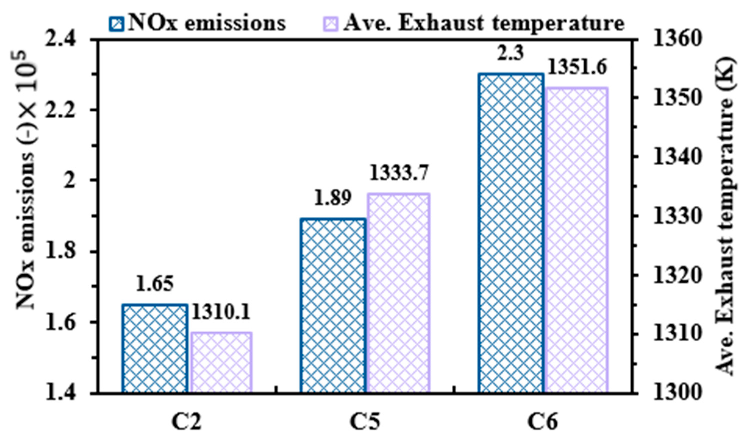
3.2. Effects of Preheating Channel Width

The preheating channel represents the source of power in the proposed design. Therefore, the optimization of its structure can potentially lead to maximizing the benefits of energy input by improving system efficiency and curtailing NOx emissions. While the previous sub-section discusses the effects of the heat-recirculating channel length, this sub-section demonstrates the effect of its width on the thermal key parameters and NOx emissions for optimization purposes. It is demonstrated that the shortest heat-recirculating channel length (C2) is conducive to slightly enhancing thermal and environmental variables. Thus, the C2 configuration with different preheating channel widths is selected for this investigation. All dimensions of the test cases examined here are provided in Table 1, and the inlet velocity and equivalence ratio are 8 m/s and unity, respectively.
Figure 8a shows the distribution of temperature over the external walls at various preheating channel widths. It can be seen that varying the channel width tends not to affect the wall temperature trends in the inlet and back wall regions; however, the wide channel structure (C2) is conducive to increasing the wall temperature from an x/L of 0.2 to 0.8. This suggests that widening such a channel exhibits a more effective means of holding a larger quantity of the high-temperature flame, which consequently improves the heat transfer to the walls. In addition, the wide heat-recirculating channel has a larger volume, and this ensures that the reversed hot gases preheat the incoming flow from the inlet at a higher degree. These conditions lead the T w , m of C2 to increase by 4.58 and 10.44 K compared to C5 and C6, respectively, as illustrated in Figure 8b. However, C2 exhibits slightly less uniformity in the wall temperature than C5 and C6, which can be attributed to blocking a relatively higher amount of thermal energy in the middle wall zone.
Figure 9 presents the variations in temperature and OH mass fraction at different widths of the heat-recirculating channel. As seen in Figure 9a, the temperature in all cases is identically distributed at the onset of the combustion region. However, increasing the width of the middle wall (C2) is conducive to holding a larger amount of high-temperature flame. This leads the solid wall to absorb more thermal energy, thereby enhancing the mean wall temperature. Furthermore, as the inner channel width transitions from wide to narrow, the volumetric space between the channel and external wall increases and, therefore, a larger quantity of high-temperature flame is allowed to propagate freely through these paths. This explains the more evenly distributed heat along the external walls in C6 compared to C2 and C5, as illustrated in Figure 8b. Figure 9b shows that the formations of OH radicals are relatively higher in the preheating channel in C6, C5, and C2, respectively. This indicates that narrowing the inner channel greatly intensifies the chemistry closer to the outlets, thus leading to the release of a greater amount of thermal energy into the atmosphere.
Figure 10 shows a comparison of NOx emissions and average exhaust temperature as a function of various preheating channel widths. Narrowing the preheating channel results in a pronounced increase in the NOx emissions, which is caused by the higher exhaust gas temperature. This supports the findings depicted in Figure 9a, as the low width of the channel increases the volume between the inner channel and the external walls, thereby allowing more hot gases to flow toward the outlets. This highlights that widening the preheating channel leads to significant benefits from the thermal energy by means of improving the heat transfer process.
Figure 11 presents the variations in exergy, radiation, and combustion efficiencies along with the pressure loss with respect to different widths of the heat-recirculating channel. The higher exhaust gas temperatures of C5 and C6 cause the exergy efficiency to decrease by 0.86 and 1.24% compared to C2, as shown in Figure 11a. In contrast, the radiation efficiencies of C2, C5, and C6 are 51.83%, 50.73%, and 49.71%, respectively, which results from the pronounced improvement in the heat absorption rate of the wall when broadening the channel width. Figure 11b illustrates that the combustion efficiencies of all the test cases are highly comparable, which indicates that the width of the preheating channel tends not to play a role in the fuel consumption rate. However, increasing the heat-recirculating width results in an increased pressure drop due to a higher quantity of combustion products being held, which requires slightly more pumping power.

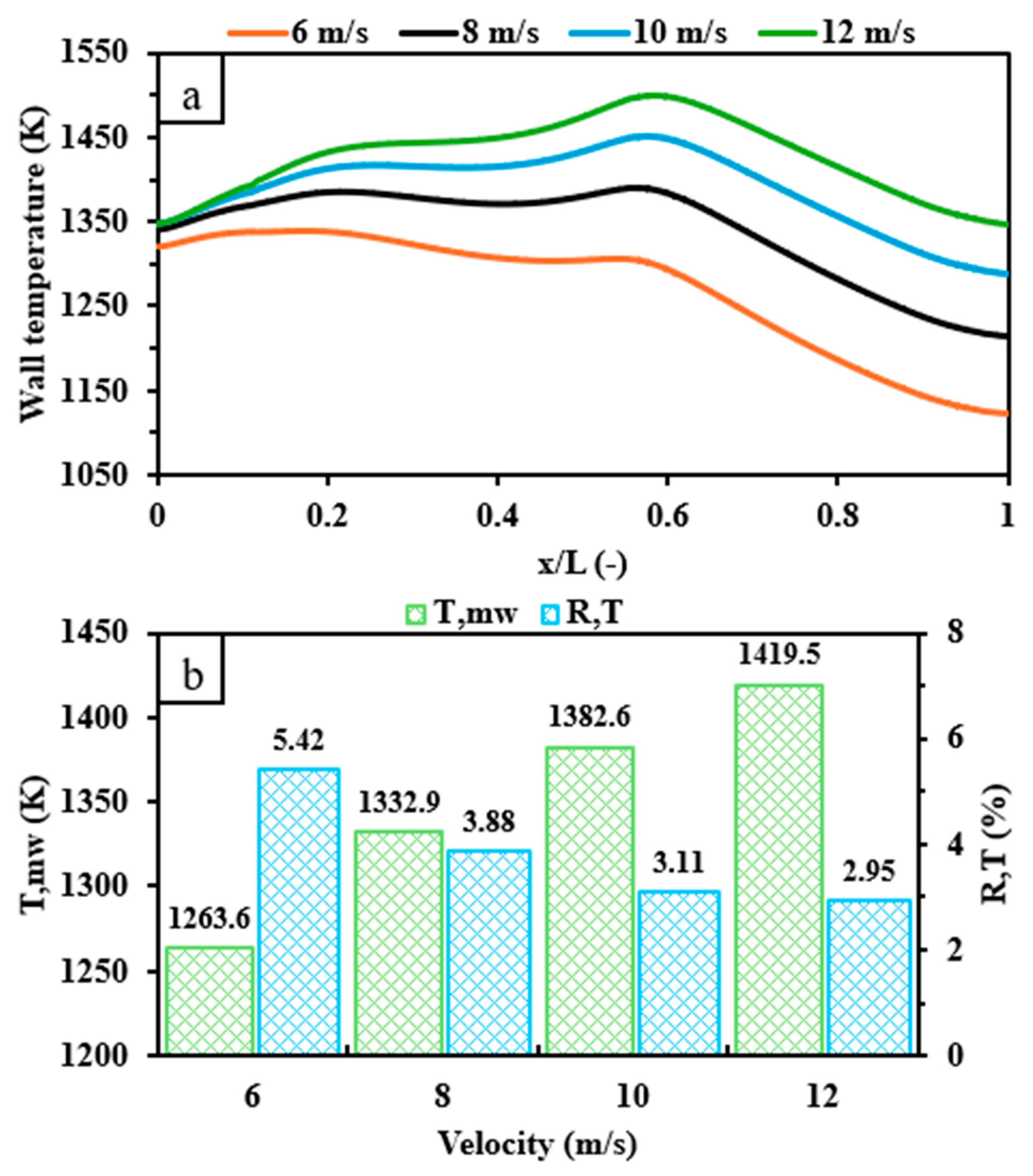
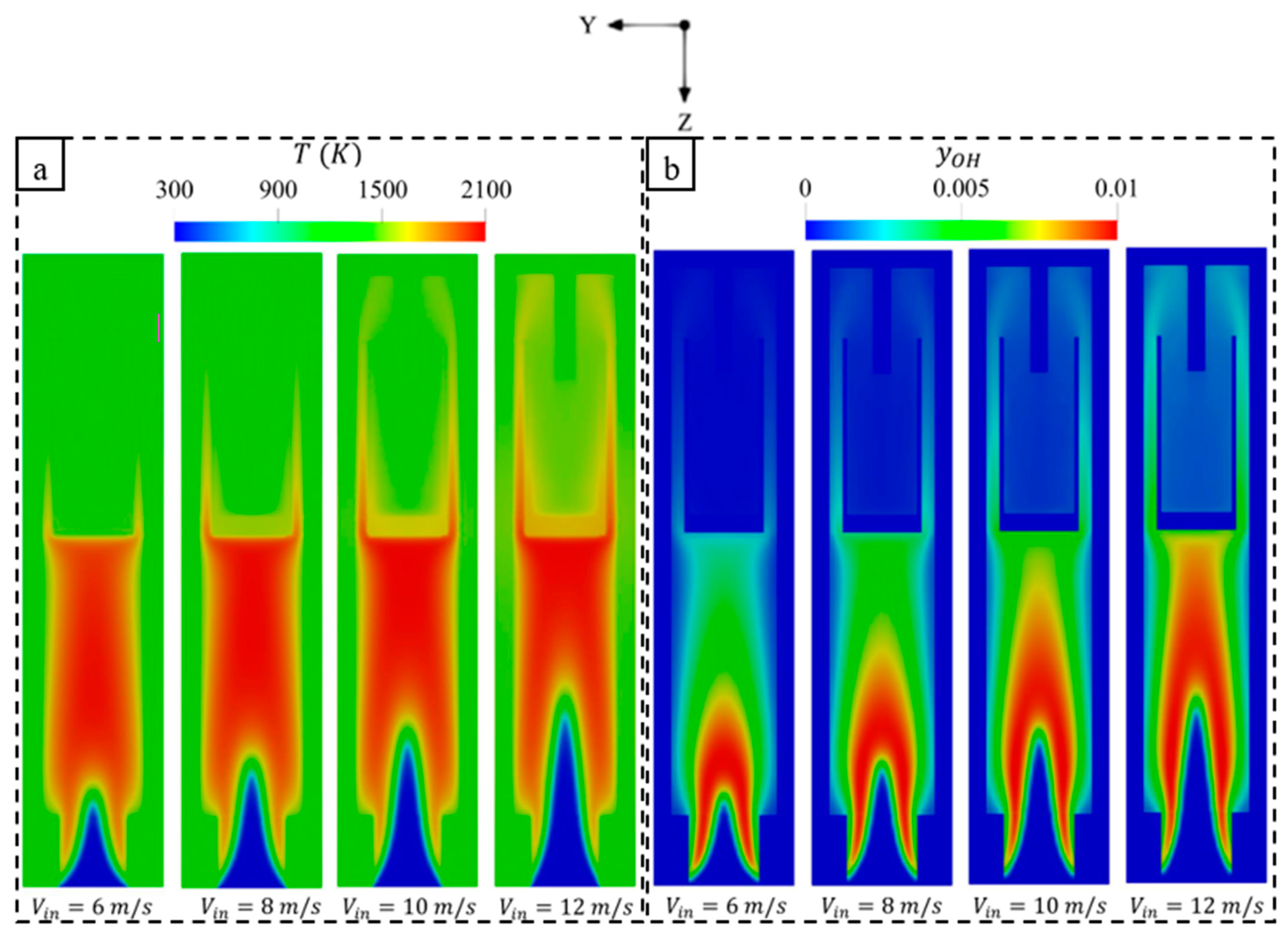
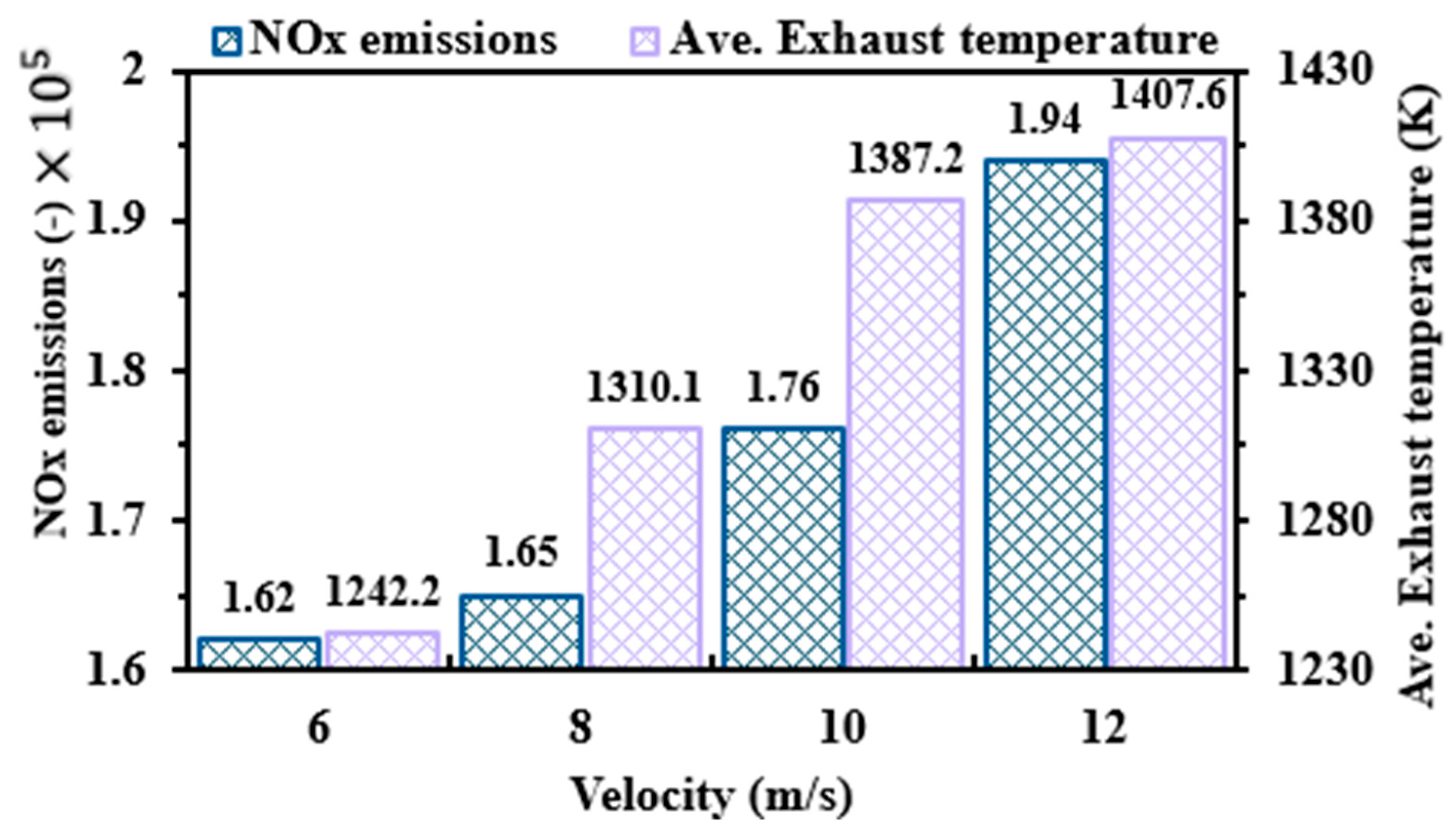
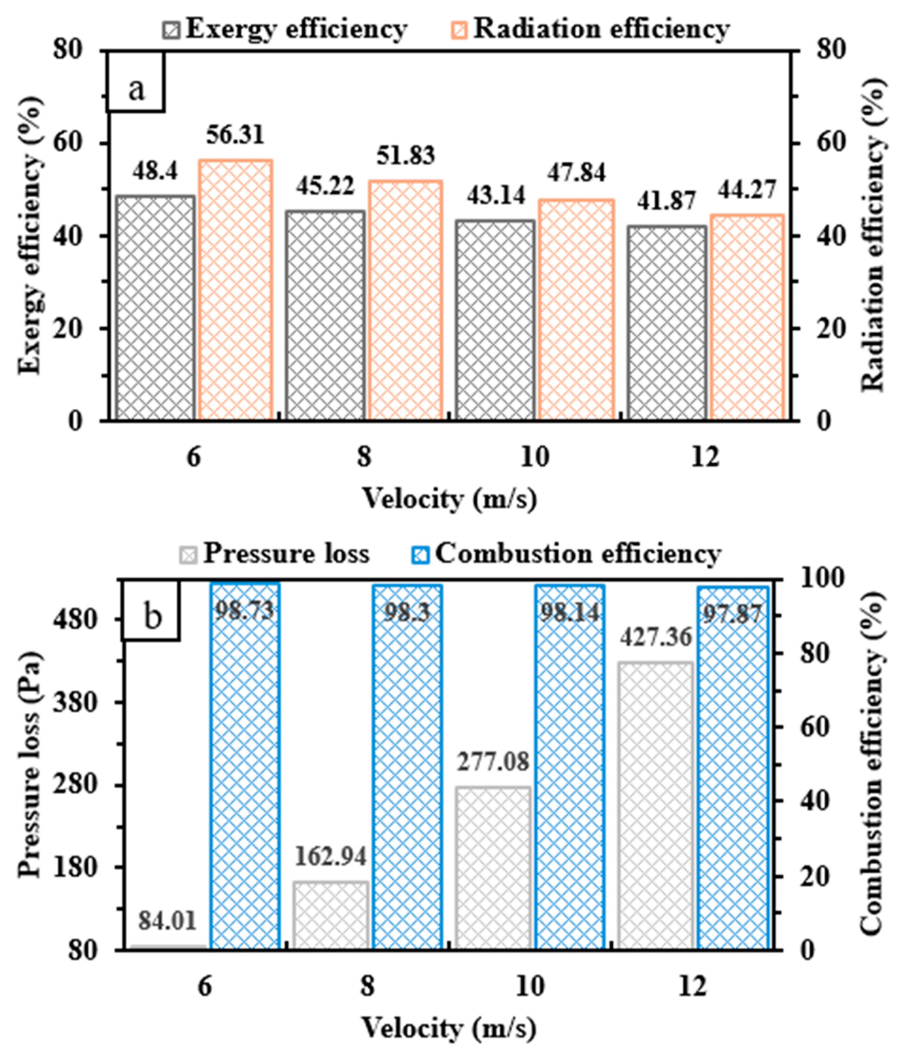
3.3. Effects of Inlet Velocity

The inlet velocity V i n of the premixed hydrogen–air mixture represents a critical variable that affects the performance and NOx emissions characteristics of the micro combustor. Conducting a comprehensive investigation to demonstrate the effects of inlet velocity on the highlighted parameters enables us to optimize the system efficiency, NOx emissions, and fuel consumption rate, particularly for hydrogen combustion, which is characterized by a high diffusion coefficient and flame speed. Therefore, a series of simulations of the C2 configuration was carried out at different inlet velocities ranging from 6 to 12 m/s while maintaining an equivalence ratio Φ equal to 1.
Figure 12a illustrates the wall temperature distribution over the dimensionless length (x/L), where L is the distance from the inlet and outlet and x is the distance from the inlet. As can be seen, three distinct outcomes result from the variations of V i n , which are at the inlet region, the back wall region, and the maximum wall temperature. At the inlet micro-combustor wall, the wall temperature of the 6 m/s case is 1319.3 K, which represents the lowest wall temperature when compared with 8, 10, and 12 m/s, as the wall temperature of the latter three cases is roughly 1345 K. This confirms that the effects of V i n are limited in this zone and vanish from 8 m/s onward. At the back wall region, the higher V i n yields an obviously higher wall temperature, as this region at 12, 10, 8, and 6 m/s is 1345.93, 1286.88, 1214.45, and 1123.99 K, respectively. Similarly, the maximum wall temperature clearly increases with increasing V i n due to the system being fed with more hydrogen and more thermal energy being released accordingly. Thus, T w , m gradually increases with increasing V i n , as shown in Figure 12b. In addition to the increase in T w , m , R T exhibits a decreasing trend as V i n approaches 12 m/s. This suggests an improvement in the wall temperature uniformity across the external wall, which can be attributed to the more optimal flame expansion at higher V i n . Furthermore, the reaction zone occurs in a better location, as it moves farther downstream with the increasing V i n owing to the diffusion coefficient being promoted by the injection of more hydrogen (as observed in Figure 13).
Figure 13 shows the distributions of temperature and OH mass fraction over the y-z cross-sectional plane. As shown in Figure 13a, the increase in V i n moves the onset of combustion downstream owing to the enhanced mass diffusion. The area occupied by the high-temperature flame with elevating V i n is narrower because the distance between the combustion initiation and middle wall is shorter. This highlights that the middle wall in such conditions holds greater thermal energy and, hence, the solid walls absorb more heat. The increase in V i n leads to a rise in the mass flow rate of hydrogen and consequently the maximum temperature.
Figure 13b illustrates that the OH radicals are widely distributed with increasing V i n because such radicals favor the high-temperature and high hydrogen consumption regions. The OH radical is known as one of the main products of hydrogen combustion; thus, its increased formations farther downstream with the elevating V i n indicate highly intensive chemical reactions [60].
Figure 14 demonstrates the changes in NOx emissions and average exhaust gas temperatures with variations in V i n from 6 to 12 m/s. The production of harmful pollution like NOx is noticeably increased in high-temperature environments [61], and hydrogen combustion releases high thermal energy owing to its high diffusion mobility and flame speed. Hence, the NOx emissions continually increase with elevations in V i n from 6 to 12 m/s. Furthermore, increasing V i n is conducive to increasing the average exhaust gas temperature, which indicates that feeding the system with a higher hydrogen flow rate results in a greater waste of thermal energy from the system. These observations suggest that lowering the inlet velocity optimizes both the performance and emission characteristics.
Figure 15 illustrates the effects of varying V i n on the exergy, radiation, and combustion efficiencies as well as the pressure loss. Increasing V i n leads both the exergy and radiation efficiencies to decrease, as depicted in Figure 15a. These reduction trends could be ascribed to the high exhaust temperature [62]. It is true that elevating V i n increases the energy input and the combustion temperature; however, the micro scale combustor seems to be limited in terms of accommodating a large amount of energy. Similarly, as shown in Figure 15b, the combustion efficiency is very high for all cases and decreases slightly with elevations in V i n because of the relatively lower consumption rate of hydrogen. In contrast, the pressure loss progressively increases when V i n increases, as shown in Figure 15b. This suggests that increasing V i n appears to significantly increase the collision rate between the incoming flow from the inlet and the middle and back walls, which leads to a need for more pumping power.

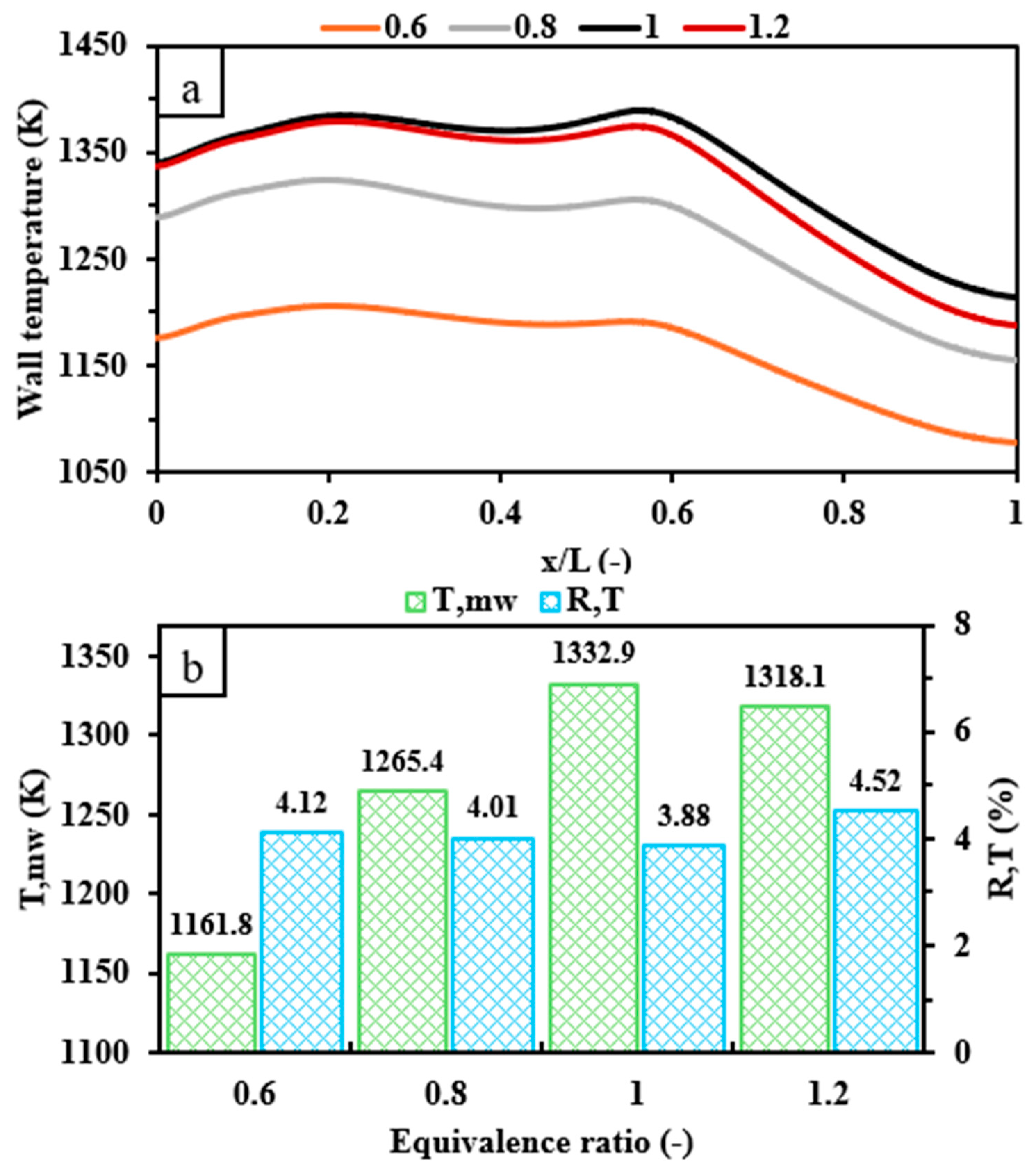
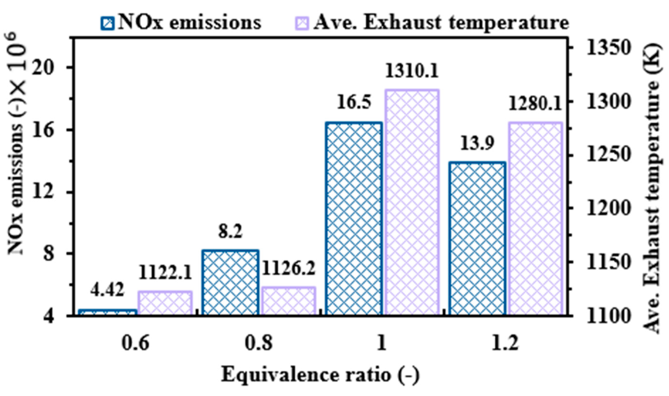
3.4. Effects of Inlet Equivalence Ratio

The equivalence ratio Φ is an important parameter in all combustion applications because it controls the fuel–oxygen mixing ratio. Thus, its proper selection ensures more complete fuel energy utilization and, consequently, high system efficiency. This sub-section discusses the effects of Φ on the wall temperature variation, the mean wall temperature, the wall temperature uniformity, the spatial distributions of temperature, and the OH mass fraction, exergy, radiation, combustion efficiencies, and pressure loss. All simulations were conducted with V i n of 8 m/s and C2 configuration.
Figure 16 presents the distribution of the wall temperature over the dimensionless length (x/L), T w , m , and R T under Φ of 0.6, 0.8, 1.0, and 1.2. It is evident from Figure 16a that the wall temperatures in the cases with an Φ of 0.6 and 0.8 are significantly lower than those with a greater Φ . This is due to the low amount of hydrogen content in the hydrogen–air mixture; thus, the thermal energy released during the combustion process is mitigated. However, the wall temperature of 1.2 Φ is roughly similar to that of the case with an Φ of 1 in the inlet region; nevertheless, the former then gradually decreases in comparison with the latter. This indicates that supplying the system with more hydrogen at a higher Φ diminishes the oxygen availability, thereby hampering the fuel reactivity and resulting in a lower combustion temperature. Figure 16b supports these observations as T w , m exhibits a continual increase from an Φ of 0.6 to 1.0 and then decreases. However, R T shows a decreasing trend, followed by an increasing trend with elevating Φ , achieving its minimum value at Φ = 1. This indicates that this particular ratio leads to the optimal uniformity of wall temperature because it results in a more even distribution of heat across the combustor walls.
Figure 16 shows the contours of the temperature and OH mass fraction variations throughout the micro combustor under different Φ , varying from 0.6 to 1.2. As depicted in Figure 16a, the high-temperature flame experiences a wider distribution when approaching the stoichiometric condition of Φ due to the greater energy input. However, the reduction of oxygen in rich conditions leads the high-temperature region to be distributed in a narrower range than that of the unity equivalence ratio. As Φ reaches richer conditions, the mass diffusion increases due to the increase in hydrogen content, and surprisingly, the onset of combustion takes place closer to the inlet. This could suggest not only that mass diffusivity controls combustion initiation but also that oxygen availability plays a critical role, in which the latter tends to dominate the former. The variation in OH radicals confirms the highlighted findings as its production rate and distribution increase from Φ = 0.6 to 1 and decrease under rich combustion conditions (See Figure 17b). The broader distribution and maximum mass fraction of OH, which is known as a highly reactive radical, indicates that the stoichiometric condition results in the highest release of thermal energy, thereby indicating that it is an optimal condition for the complete combustion of fuel.
Figure 18 provides the fluctuations in NOx emissions and average exhaust gas temperature with respect to different Φ inputs. Elevating the equivalence ratio is conducive to increasing the NOx emissions and average exhaust temperature from the low-containing fuel to stoichiometric conditions owing to the injection of more hydrogen. Nevertheless, both variables tend to decrease in rich conditions because the low amount of oxygen in the premixed mixture is not sufficient to consume all of the hydrogen quantity.
A comparison of the exergy, radiation, and combustion efficiencies along with pressure loss is shown in Figure 19. Both the exergy and radiation efficiencies exhibit an increasing trend as Φ changes from lean to stoichiometric conditions, followed by a decreasing trend in rich conditions. This could be attributed to the high content of unburned fuel released from the outlet for high fuel-containing conditions, while there is a large amount of unburned oxygen in the lean condition cases. As shown in Figure 19b, the combustion efficiencies are high for an Φ of 0.6, 0.8, and 1.0, thus indicating high hydrogen consumption rates. However, the oxygen content is insufficient to burn the high hydrogen input and thereby drastically decreases the combustion efficiency for the Φ = 1.2 case. Figure 19b demonstrates that the pressure drop is not likely to be notably affected by elevating the equivalence ratio, as the former is 196.5, 165.73, 162.94, and 150.76 at Φ of 0.6, 0.8, 1.0, and 1.2, respectively. This suggests that no significant change in pumping power is needed.

4. Conclusions

This work carries out 3-D numerical investigations of a hydrogen-fueled micro cylindrical combustor with a novel design configuration consisting of a reverse flow structure, a single-channel inlet, and a double-channel outlet. The emphasis is placed on evaluating the effects of the newly proposed structure on key thermal performance and NOx emissions. The parametric study includes varying the heat-recirculating channel length and width, inlet velocity, and inlet equivalence ratio. The main research findings of this study can be outlined as follows:
The newly proposed design is conducive to not only increasing the mean wall temperature and exergy efficiency but also reducing NOx emissions and wasted thermal energy. Interestingly, the radiation efficiency of the novel micro combustor structure is greatly enhanced by roughly 10% compared to that of the conventional micro combustor. Establishing the middle and back walls considerably increases the pressure loss, while varying the length of the preheating channel exhibits negligible effects on the pressure drop. The shortest preheating channel is optimal, as it exhibits a greatly pronounced improvement in key performance parameters and NOx pollution.
Varying the width of the preheating channel reveals that broadening this channel improves thermal performance and reduces NOx emissions due to the lower average exhaust gas temperature, indicating that the rate of heat absorption by the solid walls is increased. Nevertheless, as the middle wall employed in the micro cylindrical combustor widens, the pressure drop between the inlet and outlet increases, leading to a need for more pumping power.
Elevating the inlet velocity considerably increases the mean wall temperature and uniformity. However, injecting more hydrogen at higher inlet velocities leads to a decrease in exergy and radiation efficiencies owing to the high thermal energy released into the atmosphere, which consequently increases NOx emissions. In addition, transitioning the inlet velocity from low to high notably enhances the mass diffusion coefficient and the rate of collision between the inlet flow and the middle and back walls, eventually leading to greater pressure loss.
Increasing the inlet equivalence ratio from 0.6 to 1.0 leads to an improvement in thermal performance due to the system being fed with more hydrogen. However, a further increase in the equivalence ratio from stoichiometric to rich conditions results in lower system efficiencies because the oxygen content tends to be insufficient to combust all the fuel. This highlights that the unity equivalence ratio optimizes the performance characteristics; however, the stoichiometric condition results in the highest NOx emissions. The high fuel-containing conditions gradually decrease the pressure drop as the onset of combustion becomes closer to the inlet region.
Overall, the newly proposed design of micro cylindrical combustor potentially improves key thermal parameters and reduces NOx emissions. However, further studies are needed to achieve further optimization. These investigations can focus on the following aspects:
The effects of using a porous medium on overall system efficiency and environmental parameters.
The effects of a high-temperature environment on the structural strength of various materials with and without thermal barrier coatings to identify the most suitable for this application.

Funding

This research received no funding.

Data Availability Statement

The data presented in the study are included in the article, further inquiries can be directed to the corresponding author.

Acknowledgments

The author would like to gratefully acknowledge King Abdullah University of Science and Technology (KAUST) for their support in permitting the use of the high computing facilities to conduct the numerical investigations.

Conflicts of Interest

The author declares that he has no known competing financial interests or personal relationships that could have appeared to influence the work reported in this paper.

Nomenclature

v Velocity vector, m · s 1
P Static pressure, P a
Ι Unit tensor
k e f f Effective conductivity, W · m · K 1
Y i Mass fraction of species i
Y f u e l , i n Fuel mass fractions at the inlet
Y f u e l , o u t Fuel mass fractions at the outlet
R i Reaction net rate of production of species i
h j Enthalpy of species j, J · k g 1
S h Enthalpy source term of fluid, W · m 3
Q Total heat loss, W
Q c o n Heat losses by convection, W
Q r a d Heat losses by radiation, W
h Natural convection heat transfer coefficient W · m 2 · K 1
A c Surface area of the outer wall, m 2
A i Outer wall area of cell i, m 2
E x i n Inlet exergy, W
E x e g Total exergy losses, W
E x d e s Uncounted exergy destruction, W
E x l o s s Energy loss from the combustion exhaust gas, W
T e g Exhaust gas temperature, K
T w , m Area-weighted-mean wall temperature, K
T w Temperature of external wall, K
T Ambient temperature, K
T i Outer wall temperature of cell i, K
R T Wall temperature uniformity
m ˙ f u e l   Mass flow rate of fuel, k g · s 1
m ˙ i n l e t   Mass flow rate of inlet flow, k g · s 1
Q L H V   Lower heating value M J · k g 1
Greek letters
ρ Mixture gas density, K g · m 3
μ Molecular viscosity, P a · s
ε Emissivity of the solid surface
σ Stephan–Boltzmann constant, 5.67 × 10 8   W · m 2 K 4
Φ Equivalence ratio
η e x e r g y Exergy efficiency
η r a d i a t i o n Radiation efficiency
η c o m b u s t i o n Combustion efficiency

References

  1. Nicoletti, G.; Arcuri, N.; Nicoletti, G.; Bruno, R. A Technical and Environmental Comparison between Hydrogen and Some Fossil Fuels. Energy Convers. Manag. 2015, 89, 205–213. [Google Scholar] [CrossRef]
  2. Fu, J.; Liu, J.; Feng, R.; Yang, Y.; Wang, L.; Wang, Y. Energy and Exergy Analysis on Gasoline Engine Based on Mapping Characteristics Experiment. Appl. Energy 2013, 102, 622–630. [Google Scholar] [CrossRef]
  3. Shindell, D.; Smith, C.J. Climate and Air-Quality Benefits of a Realistic Phase-out of Fossil Fuels. Nature 2019, 573, 408–411. [Google Scholar] [CrossRef]
  4. Xue, Z.; Yan, Y.; He, Z.; Shen, K.; Zhang, C. Comprehensive Numerical Insight the Thermal Performance Improvement of the Micro Combustors with Internal Bionic Y-Shaped Fins for Micro-Thermal Voltaic System Applications. Fuel 2022, 318, 123610. [Google Scholar] [CrossRef]
  5. Kobayashi, H.; Hayakawa, A.; Somarathne, K.D.K.A.; Okafor, E.C. Science and Technology of Ammonia Combustion. Proc. Combust. Inst. 2019, 37, 109–133. [Google Scholar] [CrossRef]
  6. Staffell, I.; Scamman, D.; Abad, A.V.; Balcombe, P.; Dodds, P.E.; Ekins, P.; Shah, N.; Ward, K.R. The Role of Hydrogen and Fuel Cells in the Global Energy System. Energy Environ. Sci. 2019, 12, 463–491. [Google Scholar] [CrossRef]
  7. Yang, Y.; Tong, L.; Yin, S.; Liu, Y.; Wang, L.; Qiu, Y.; Ding, Y. Status and Challenges of Applications and Industry Chain Technologies of Hydrogen in the Context of Carbon Neutrality. J. Clean. Prod. 2022, 376, 134347. [Google Scholar] [CrossRef]
  8. Meher Kotay, S.; Das, D. Biohydrogen as a Renewable Energy Resource—Prospects and Potentials. Int. J. Hydrogen Energy 2008, 33, 258–263. [Google Scholar] [CrossRef]
  9. Hoang, A.T.; Foley, A.M.; Nižetić, S.; Huang, Z.; Ong, H.C.; Ölçer, A.I.; Pham, V.V.; Nguyen, X.P. Energy-Related Approach for Reduction of CO2 Emissions: A Critical Strategy on the Port-to-Ship Pathway. J. Clean. Prod. 2022, 355, 131772. [Google Scholar] [CrossRef]
  10. Mohanakrishna, G.; Sneha, N.P.; Rafi, S.M.; Sarkar, O. Dark Fermentative Hydrogen Production: Potential of Food Waste as Future Energy Needs. Sci. Total Environ. 2023, 888, 163801. [Google Scholar] [CrossRef]
  11. Koten, H. Hydrogen Effects on the Diesel Engine Performance and Emissions. Int. J. Hydrogen Energy 2018, 43, 10511–10519. [Google Scholar] [CrossRef]
  12. Zeldovich, I.B.; Barenblatt, G.I.; Librovich, V.B.; Makhviladze, G.M. Mathematical Theory of Combustion and Explosions; Consultants Bureau: New York, NY, USA, 1985. [Google Scholar]
  13. Sirignano, W.; Merzhanov, A.; Luca, L.D. Advances in Combustion Science: In Honor of Ya. B. Zel’dovich; AIAA: Reston, VA, USA, 1997; ISBN 978-1-56347-178-0. [Google Scholar]
  14. Chia, L.C.; Feng, B. The Development of a Micropower (Micro-Thermophotovoltaic) Device. J. Power Sources 2007, 165, 455–480. [Google Scholar] [CrossRef]
  15. Chen, N.; Gan, Y.; Luo, Y.; Jiang, Z. A Review on the Technology Development and Fundamental Research of Electrospray Combustion of Liquid Fuel at Small-Scale. Fuel Process. Technol. 2022, 234, 107342. [Google Scholar] [CrossRef]
  16. Ju, Y.; Maruta, K. Microscale Combustion: Technology Development and Fundamental Research. Prog. Energy Combust. Sci. 2011, 37, 669–715. [Google Scholar] [CrossRef]
  17. Maruta, K. Micro and Mesoscale Combustion. Proc. Combust. Inst. 2011, 33, 125–150. [Google Scholar] [CrossRef]
  18. Shirsat, V.; Gupta, A.K. A Review of Progress in Heat Recirculating Meso-Scale Combustors. Appl. Energy 2011, 88, 4294–4309. [Google Scholar] [CrossRef]
  19. Yilmaz, H.; Cam, O.; Tangoz, S.; Yilmaz, I. Effect of Different Turbulence Models on Combustion and Emission Characteristics of Hydrogen/Air Flames. Int. J. Hydrogen Energy 2017, 42, 25744–25755. [Google Scholar] [CrossRef]
  20. Chou, S.K.; Yang, W.M.; Chua, K.J.; Li, J.; Zhang, K.L. Development of Micro Power Generators—A Review. Appl. Energy 2011, 88, 1–16. [Google Scholar] [CrossRef]
  21. Peng, Q.; Yang, W.; E, J.; Xu, H.; Li, Z.; Tay, K.; Zeng, G.; Yu, W. Investigation on Premixed H2/C3H8/Air Combustion in Porous Medium Combustor for the Micro Thermophotovoltaic Application. Appl. Energy 2020, 260, 114352. [Google Scholar] [CrossRef]
  22. Wang, F.; Li, X.; Feng, S.; Yan, Y. Influence of Porous Media Aperture Arrangement on CH4/Air Combustion Characteristics in Micro Combustor. Processes 2021, 9, 1747. [Google Scholar] [CrossRef]
  23. Qian, P.; Liu, M.; Li, X.; Xie, F.; Huang, Z.; Luo, C.; Zhu, X. Effects of Bluff-Body on the Thermal Performance of Micro Thermophotovoltaic System Based on Porous Media Combustion. Appl. Therm. Eng. 2020, 174, 115281. [Google Scholar] [CrossRef]
  24. Wang, Y.; Zhou, Z.; Yang, W.; Zhou, J.; Liu, J.; Wang, Z.; Cen, K. Instability of Flame in Micro-Combustor under Different External Thermal Environment. Exp. Therm. Fluid Sci. 2011, 35, 1451–1457. [Google Scholar] [CrossRef]
  25. Norton, D.G.; Wetzel, E.D.; Vlachos, D.G. Fabrication of Single-Channel Catalytic Microburners:  Effect of Confinement on the Oxidation of Hydrogen/Air Mixtures. Ind. Eng. Chem. Res. 2004, 43, 4833–4840. [Google Scholar] [CrossRef]
  26. Tang, A.; Pan, J.; Yang, W.; Xu, Y.; Hou, Z. Numerical Study of Premixed Hydrogen/Air Combustion in a Micro Planar Combustor with Parallel Separating Plates. Int. J. Hydrogen Energy 2015, 40, 2396–2403. [Google Scholar] [CrossRef]
  27. Rong, H.; Zhao, D.; Cai, T.; Becker, S. Enhancing Thermal and Exergy Performances in a CO2-Free Micro-Combustor with Reverse Flow Double-Channel Outlet Structure. Appl. Therm. Eng. 2023, 233, 121180. [Google Scholar] [CrossRef]
  28. Zhao, H.; Zhao, D.; Becker, S. Thermal Performances Investigation on an Ammonia-Fuelled Heat-Recirculating Micro-Combustor with Reduced Chemical Mechanism. Appl. Therm. Eng. 2024, 236, 121685. [Google Scholar] [CrossRef]
  29. Rong, H.; Zhao, H.; Cai, T. Thermodynamic and Emission Analysis of an Ammonia Fueled Micro-Combustor with Double-Channel Reverse Flow Structure. Int. J. Hydrogen Energy 2024, 49, 1303–1314. [Google Scholar] [CrossRef]
  30. Cai, T.; Zhao, D.; Sun, Y.; Ni, S.; Li, W.; Guan, D.; Wang, B. Evaluation of NOx Emissions Characteristics in a CO2-Free Micro-Power System by Implementing a Perforated Plate. Renew. Sustain. Energy Rev. 2021, 145, 111150. [Google Scholar] [CrossRef]
  31. ANSYS Fluent User’s Guide, Release 23.1; ANSYS, Inc.: Canonsburg, PA, USA, 2023.
  32. Zeldovich, Y.B. Selected Works of Yakov Borisovich Zeldovich; Princeton University Press: Princeton, NJ, USA, 2014. [Google Scholar]
  33. Fenimore, C.P. Formation of Nitric Oxide in Premixed Hydrocarbon Flames. Symp. Int. Combust. 1971, 13, 373–380. [Google Scholar] [CrossRef]
  34. Ni, S.; Zhao, D.; Sellier, M.; Li, J.; Chen, X.; Li, X.; Cao, F.; Li, W. Thermal Performances and Emitter Efficiency Improvement Studies on Premixed Micro-Combustors with Different Geometric Shapes for Thermophotovoltaics Applications. Energy 2021, 226, 120298. [Google Scholar] [CrossRef]
  35. Yang, X.; Yu, B.; Peng, X.; Zhou, H. Investigation of Thermal Performance and Energy Conversion in a Novel Planar Micro-Combustor with Four-Corner Entrances for Thermo-Photovoltaic Power Generators. J. Power Sources 2021, 515, 230625. [Google Scholar] [CrossRef]
  36. Sun, Y.; Cai, T.; Zhao, D. Thermal Performance and NOx Emission Characteristics Studies on a Premixed Methane-Ammonia-Fueled Micro-Planar Combustor. Fuel 2021, 291, 120190. [Google Scholar] [CrossRef]
  37. Kuo, C.H.; Ronney, P.D. Numerical Modeling of Non-Adiabatic Heat-Recirculating Combustors. Proc. Combust. Inst. 2007, 31, 3277–3284. [Google Scholar] [CrossRef]
  38. Shih, T.-H.; Liou, W.W.; Shabbir, A.; Yang, Z.; Zhu, J. A New k-ϵ Eddy Viscosity Model for High Reynolds Number Turbulent Flows. Comput. Fluids 1995, 24, 227–238. [Google Scholar] [CrossRef]
  39. Zhao, H.; Zhao, D.; Becker, S.; Zhang, Y. NO Emission and Enhanced Thermal Performances Studies on Counter-Flow Double-Channel Hydrogen/Ammonia-Fuelled Microcombustors with Oval-Shaped Internal Threads. Fuel 2023, 341, 127665. [Google Scholar] [CrossRef]
  40. Mousavi, S.M.; Sotoudeh, F.; Jun, D.; Lee, B.J.; Esfahani, J.A.; Karimi, N. On the Effects of NH3 Addition to a Reacting Mixture of H2/CH4 under MILD Combustion Regime: Numerical Modeling with a Modified EDC Combustion Model. Fuel 2022, 326, 125096. [Google Scholar] [CrossRef]
  41. Cai, T.; Zhao, D.; Karimi, N. Optimizing Thermal Performance and Exergy Efficiency in Hydrogen-Fueled Meso-Combustors by Applying a Bluff-Body. J. Clean. Prod. 2021, 311, 127573. [Google Scholar] [CrossRef]
  42. Ni, S.; Zhao, D.; You, Y.; Huang, Y.; Wang, B.; Su, Y. NOx Emission and Energy Conversion Efficiency Studies on Ammonia-Powered Micro-Combustor with Ring-Shaped Ribs in Fuel-Rich Combustion. J. Clean. Prod. 2021, 320, 128901. [Google Scholar] [CrossRef]
  43. Ni, S.; Zhao, D.; Wu, W.; Guan, Y. NOx Emission Reduction Reaction of Ammonia-Hydrogen with Self-Sustained Pulsating Oscillations. Therm. Sci. Eng. Prog. 2020, 19, 100615. [Google Scholar] [CrossRef]
  44. Wan, J.; Fan, A.; Yao, H.; Liu, W. Flame-Anchoring Mechanisms of a Micro Cavity-Combustor for Premixed H2/Air Flame. Chem. Eng. J. 2015, 275, 17–26. [Google Scholar] [CrossRef]
  45. Yang, W.M.; Chua, K.J.; Pan, J.F.; Jiang, D.Y.; An, H. Development of Micro-Thermophotovoltaic Power Generator with Heat Recuperation. Energy Convers. Manag. 2014, 78, 81–87. [Google Scholar] [CrossRef]
  46. Li, J.; Chou, S.K.; Li, Z.W.; Yang, W.M. Characterization of Wall Temperature and Radiation Power through Cylindrical Dump Micro-Combustors. Combust. Flame 2009, 156, 1587–1593. [Google Scholar] [CrossRef]
  47. Li, J.; Chou, S.K.; Huang, G.; Yang, W.M.; Li, Z.W. Study on Premixed Combustion in Cylindrical Micro Combustors: Transient Flame Behavior and Wall Heat Flux. Exp. Therm. Fluid Sci. 2009, 33, 764–773. [Google Scholar] [CrossRef]
  48. Cai, T.; Zhao, D. Effects of Fuel Composition and Wall Thermal Conductivity on Thermal and NOx Emission Performances of an Ammonia/Hydrogen-Oxygen Micro-Power System. Fuel Process. Technol. 2020, 209, 106527. [Google Scholar] [CrossRef]
  49. Li, J.; Huang, J.; Chen, X.; Zhao, D.; Shi, B.; Wei, Z.; Wang, N. Effects of Heat Recirculation on Combustion Characteristics of N-Heptane in Micro Combustors. Appl. Therm. Eng. 2016, 109, 697–708. [Google Scholar] [CrossRef]
  50. He, Z.; Yan, Y.; Zhao, T.; Feng, S.; Li, X.; Zhang, L.; Zhang, Z. Heat Transfer Enhancement and Exergy Efficiency Improvement of a Micro Combustor with Internal Spiral Fins for Thermophotovoltaic Systems. Appl. Therm. Eng. 2021, 189, 116723. [Google Scholar] [CrossRef]
  51. Sahoo, B.B.; Saha, U.K.; Sahoo, N. Diagnosing the Effects of Pilot Fuel Quality on Exergy Terms in a Biogas Run Dual Fuel Diesel Engine. Int. J. Exergy 2012, 10, 77–93. [Google Scholar] [CrossRef]
  52. Stepanov, V.S. Chemical Energies and Exergies of Fuels. Energy 1995, 20, 235–242. [Google Scholar] [CrossRef]
  53. Tong, J.; Cai, T. Enhancing Thermal Performance, Exergy and Thermodynamics Efficiency of Premixed Methane/Air Micro-Planar Combustor in Micro-Thermophotovoltaic Systems. Energies 2023, 16, 118. [Google Scholar] [CrossRef]
  54. Rahbari, A.; Homayoonfar, S.; Valizadeh, E.; Aligoodarz, M.R.; Toghraie, D. Effects of Micro-Combustor Geometry and Size on the Heat Transfer and Combustion Characteristics of Premixed Hydrogen/Air Flames. Energy 2021, 215, 119061. [Google Scholar] [CrossRef]
  55. Peng, Q.; Yang, W.; E, J.; Li, Z.; Xu, H.; Fu, G.; Li, S. Investigation on H2/Air Combustion with C3H8 Addition in the Combustor with Part/Full Porous Medium. Energy Convers. Manag. 2021, 228, 113652. [Google Scholar] [CrossRef]
  56. Wenming, Y.; Siawkiang, C.; Chang, S.; Hong, X.; Zhiwang, L. Effect of Wall Thickness of Micro-Combustor on the Performance of Micro-Thermophotovoltaic Power Generators. Sens. Actuators Phys. 2005, 119, 441–445. [Google Scholar] [CrossRef]
  57. Zuo, W.; Zhang, Y.; Li, Q.; Li, J.; He, Z. Numerical Investigations on Hydrogen-Fueled Micro-Cylindrical Combustors with Cavity for Micro-Thermophotovoltaic Applications. Energy 2021, 223, 120098. [Google Scholar] [CrossRef]
  58. De Robbio, R.; Mancaruso, E. Hydrogen Combustion Analysis via Infrared and Visible Optical Diagnostics Combined with CFD in a Dual Fuel Engine at Low Load. Int. J. Hydrogen Energy 2024, 81, 418–435. [Google Scholar] [CrossRef]
  59. Rajak, U.; Panchal, M.; Viswanath Allamraju, K.; Nashine, P.; Nath Verma, T.; Pugazhendhi, A. A Numerical Investigation on a Diesel Engine Characteristic Fuelled Using 3D CFD Approach. Fuel 2024, 368, 131488. [Google Scholar] [CrossRef]
  60. Ranga Dinesh, K.K.J.; Shalaby, H.; Luo, K.H.; van Oijen, J.A.; Thévenin, D. High Hydrogen Content Syngas Fuel Burning in Lean Premixed Spherical Flames at Elevated Pressures: Effects of Preferential Diffusion. Int. J. Hydrogen Energy 2016, 41, 18231–18249. [Google Scholar] [CrossRef]
  61. Köse, H.; Ciniviz, M. An Experimental Investigation of Effect on Diesel Engine Performance and Exhaust Emissions of Addition at Dual Fuel Mode of Hydrogen. Fuel Process. Technol. 2013, 114, 26–34. [Google Scholar] [CrossRef]
  62. Bajelani, M.; Ansari, M.R.; Nadimi, E. A Comprehensive Study of Effective Parameters on the Thermal Performance of Porous Media Micro Combustor in Thermo Photovoltaic Systems. Appl. Therm. Eng. 2023, 231, 120846. [Google Scholar] [CrossRef]
Figure 1. Schematic representation of the newly proposed design of micro cylindrical combustor, where L stands for length, D diameter and t thickness.
Processes 12 01848 g001
Figure 2. Variations of (a) wall temperature with respect to the dimensionless length and (b) area-weighted-mean wall temperature T w , m and wall temperature uniformity R T of 131,922 (Mesh-I), 451,954 (Mesh-II) and 796,770 (Mesh-III) cell numbers.
Processes 12 01848 g002
Figure 3. A comparison of numerically predicted mean wall temperature of the current simulations with experimental [56] and computational [57] findings at various equivalence ratios.
Processes 12 01848 g003
Figure 4. A comparison of (a) wall temperature variations with respect to the dimensionless length (x/L) and (b) area-weighted-mean wall temperature T w , m along with wall temperature uniformity R T for C1, C2, C3 and C4 test cases.
Processes 12 01848 g004
Figure 5. Distributions of (a) temperature and (b) OH mass fraction with respect to for C1, C2, C3 and C4 test cases.
Processes 12 01848 g005
Figure 6. A comparison of NOx emissions and exhaust gas temperature for different preheating channel structures.
Processes 12 01848 g006
Figure 7. Numerically predicted (a) exergy and radiation efficiencies, and (b) pressure loss and combustion efficiency with respect to different preheating channel structures.
Processes 12 01848 g007
Figure 8. Variations in (a) the wall temperature with respect to the dimensionless length (x/L), and (b) area-weighted-mean wall temperature T w , m along with wall temperature uniformity R T at different preheating channel widths.
Processes 12 01848 g008
Figure 9. Comparison between (a) temperature and (b) OH mass fraction distributions throughout the combustion chamber with respect to various widths of preheating channel.
Processes 12 01848 g009
Figure 10. NOx emissions and average exhaust gas temperature variations at different widths of heat recirculating channel.
Processes 12 01848 g010
Figure 11. Variations in (a) exergy and radiation efficiencies and (b) pressure loss and combustion efficiency at different widths of preheating channel.
Processes 12 01848 g011
Figure 12. Effects of inlet velocity variations on (a) the distribution of wall temperature with respect to the dimensionless length (x/L), and (b) area-weighted-mean wall temperature T w , m along with wall temperature uniformity R T .
Processes 12 01848 g012
Figure 13. Contours of (a) temperature and (b) OH mass fraction distributions on cross-section at various inlet velocities.
Processes 12 01848 g013
Figure 14. Variations in NOx emissions and average exhaust temperature with respect to a range of V i n .
Processes 12 01848 g014
Figure 15. A comparison of (a) exergy and radiation efficiencies along with (b) pressure loss and combustion efficiency at various V i n .
Processes 12 01848 g015
Figure 16. A comparison of (a) wall temperature variations with respect to the dimensionless length (x/L) and (b) T w , m along with R T as a function of Φ .
Processes 12 01848 g016
Figure 17. Spatial distributions of (a) temperature and (b) OH mass fraction throughout the micro combustor at various Φ .
Processes 12 01848 g017
Figure 18. A comparison of NOx emissions and average exhaust temperature at different Φ .
Processes 12 01848 g018
Figure 19. Numerically computed (a) exergy and radiation efficiencies as well as (b) pressure loss and combustion efficiency under different inlet equivalence ratios.
Processes 12 01848 g019
Table 1. Dimensions of newly proposed micro cylindrical combustor.
VariablesValue (mm)
Case 1Case 2Case 3Case 4Case 5Case 6
LengthL1181818181818
L2NA15.515.515.515.515.5
L3NA46888
L4NA97555
L5NA22222
L6NA0.50.50.50.50.5
L7NA0.940.940.940.940.94
L8NA1.951.951.951.450.95
L9NA0.40.40.40.650.9
DiameterD1444444
D2333333
D3222222
Thicknesst1NA0.1250.1250.1250.1250.125
Table 2. Summary of numerical settings employed in this study.
ParameterMethod
FlowTurbulent
Chemistry–turbulence interactionEddy dissipation concept (EDC)
DiscretizationSecond-order UPWIND scheme
Pressure–velocity couplingSIMPLE algorithm
SegregateSegregate/implicit (under-relaxation method)
SoftwareANSYS Fluent R1 2023
Mixture physical propertiesDensity: incompressible-ideal-gas law
Specific heat: mixing-law
Thermal conductivity: ideal gas mixing law
Viscosity: ideal gas mixing law
Mass diffusivity: kinetic theory
Table 3. Thermal properties of steel.
PropertyUnitValues
Density k g / m 3 8000
Thermal conductivity W / m · K 12
Specific heat J / k g · K 503
Emissivity-0.85
Table 4. Boundary conditions implemented in the simulations.
BoundaryParametersValues
InletVelocity6, 8, 10, 12 m/s
Gauge pressure0 Pa
Turbulent intensity5%
Hydraulic diameter2 mm
Temperature300 K
OutletGauge pressure0 Pa
Turbulent intensity5%
Hydraulic diameter2 mm
Inner wallInterface No-slipZero-flux for all species
Thermal conditionCoupled
MaterialSteel
Outer wallHeat transfer coefficient10 W/m2·K
Emissivity0.85
Disclaimer/Publisher’s Note: The statements, opinions and data contained in all publications are solely those of the individual author(s) and contributor(s) and not of MDPI and/or the editor(s). MDPI and/or the editor(s) disclaim responsibility for any injury to people or property resulting from any ideas, methods, instructions or products referred to in the content.

