Article

Effect on Top-Coal Mass Failure under Load–Unload Induced by Shield Support

1
College of Intelligent Construction and Civil Engineering, Zhongyuan University of Technology, Zhengzhou 450007, China
2
School of Civil Engineering, Zhengzhou University of Technology, Zhengzhou 450044, China
3
Zimasco Private Limited, Harare 00263, Zimbabwe
4
College of Energy and Mining Engineering, China University of Mining and Technology (Beijing), Beijing 100083, China
5
Department of Architecture and Civil Engineering, City University of Hong Kong, Hong Kong 999077, China
6
Department of Northwest Geological Exploration Institute, China Metallurgical Geology Bureau, Xi’an 710119, China
7
Institutes of Science and Development, Chinese Academy of Sciences, Beijing 100190, China
*
Author to whom correspondence should be addressed.
Processes 2024, 12(9), 1872; https://doi.org/10.3390/pr12091872
Submission received: 21 July 2024 / Revised: 27 August 2024 / Accepted: 30 August 2024 / Published: 1 September 2024
(This article belongs to the Section Energy Systems)

Abstract

:
Prior to being released, the top coal of a fully mechanized caving face typically experiences the effects of mining-induced pressure and disturbances from the hydraulic support’s canopy. To investigate the promoting effect of canopy disturbances in the support-controlled area on the damage of top coal during fully mechanized top-coal caving mining, block instability theory and discrete block numerical simulation methods were employed. The instability modes during the initial support and cyclic disturbance stages were analyzed. The fracture evolution and displacement distribution curves were studied for coal bodies with strengths of 3.1 MPa, 15.0 MPa, and 29.5 MPa under the mining influence and support strengths of 0.5 MPa, 1.0 MPa, and 1.5 MPa during the initial support and cyclic disturbance processes. The results showed that during the initial support stage, the instability of the block-structured coal body exhibited four modes as follows: inter-block breakage, inter-block delamination, intra-block fracture expansion, and inter-block sliding. During the cyclic disturbance stage, the coal body instability showed three modes as follows: inter-block sliding, intra-block fracture expansion, and inter-block rotation. The disturbance from the support had little impact on the fragmentation of both low-strength and high-strength coal bodies. However, small support forces combined with multiple cycles of disturbance had an enhancing effect on the instability of medium-strength block-structured top coal.

1. Introduction

During fully mechanized caving mining, the failure of the top coal undergoes two stages: the stage where the abutment pressure ahead of the working face acts on the coal body and the stage where the hydraulic support top beam and roof exert unidirectional compression on the coal body [1]. The former is an inevitable process in mining and is considered a passive action, whereas the latter can be controlled by manually adjusting the support top beam, making the top beam actively break the coal body, which is thus considered an active action.
In the stage of abutment pressure action, the bending moment of the overlying hanging strata ahead of the top-coal caving face forms a certain range of abutment pressure and smaller horizontal stress within the coal body. These stresses externally manifest as displacements, including vertical and horizontal displacements of the top coal [2,3]. Some researchers simulated the stress loading path of the mining process using a triaxial testing machine with an axial pressure increase and confining pressure decrease, considering the effect of horizontal stress. During top-coal caving, the lower top coal experiences processes such as vertical stress loading, horizontal stress unloading, and cycles of vertical stress loading and unloading while maintaining constant horizontal stress [4,5,6,7]. The literature of [8,9] uses the number of fractures as a criterion to classify the fractures in the coal-rock mass ahead of the mining face into an isolated fracture zone, a tensile fracture zone, a shear fracture zone, and a post-peak abutment pressure fracture zone. Literature [10] suggests that advanced abutment pressure significantly influences the fracture propagation in the middle and lower top coal, playing an important role in the destruction of the top coal. Repeated disturbances from the supports in the roof control area positively impact the fracturing of the lower top coal. Understanding the failure mechanisms of top coal can help prevent roof collapses, which are among the most common and dangerous accidents in mines. Roof collapses not only lead to coal seam collapses but can also trigger more extensive mine collapses, posing significant threats to workers’ safety. Comprehending the failure process of top coal aids in optimizing the support parameters and mining schemes, thereby enhancing the efficiency of coal extraction. During the failure of top coal, the support equipment is subjected to intense forces from both the roof and the coal body. If the failure mechanisms of top coal are not well understood, it may result in uneven pressure on the support equipment, which could lead to equipment damage or failure. This not only increases the costs of maintenance and replacement but also causes production halts, thereby affecting the overall economic efficiency of the mine. In summary, inadequate control over top-coal failures can lead to a series of issues, such as the falling of large top-coal blocks, frequent formation of arch structures during extraction, poor balance in top-coal extraction, and low top-coal recovery rates. These issues severely impact the safety, efficiency, and environmental sustainability of mining operations [11,12].
For coal bodies of different strengths, field observations of top-coal displacement and finite element calculations of top-coal displacement indicate that soft coal near the coal drawing opening presents a granular state; medium-hard coal shows a high block coal rate after several cycles of support lifting and lowering in the roof control area; hard coal seams have larger block sizes of fractured top coal, with minimal impact from the support top beam on top-coal failure [13,14,15]. Figure 1 illustrates the large block hanging roof structure formed by top coal above the support top beam. Pang Yihui et al. believe that increasing the initial support force and improving the support structural parameters can somewhat enhance the crushing effect on hard top coal [16,17,18,19]. As the mining height increases, the phenomenon of stress concentration on the top coal intensifies. This concentrated stress leads to the generation and propagation of internal fractures within the top coal, thereby accelerating the fragmentation process. Greater mining heights cause the top coal to more easily develop vertical and inclined fractures under the compressive forces exerted by the supports and top beams ahead of the working face. Under conditions of high mining heights, the coal body has to bear greater self-weight and roof pressure, thus requiring a higher coal body strength. If the coal strength is relatively low, it becomes more prone to fragmentation and even overall instability during the mining process. In the context of comprehensive mechanized top-coal caving with large mining heights in extremely thick coal seams, poor top-coal collapse characteristics can lead to severe spalling and low recovery rates [20]. Additionally, because of the high caving height in large mining heights, the top coal may exhibit uneven fragmentation before being drawn out. It is necessary to arrange loosening blasting boreholes between the supports or utilize the disturbances from the support top beam and the canopy beam to break the top coal into smaller blocks. High top-coal caving heights often result in uneven fragmentation of the top coal. Under such conditions, the coal blocks are easily disturbed by the support equipment, leading to the formation of large coal blocks along with smaller fragments. This uneven fragmentation can negatively impact recovery efficiency. Due to the uneven fragmentation caused by high top-coal caving heights, additional measures such as arranging loosening blast holes may be necessary to further break down the top coal. This not only increases the production costs but also potentially raises the risk to workers. According to Yue, it is recommended to determine the reasonable spacing, length, and inclination of drill holes based on the pressure relief range of the blasting fractures [21].
In the mining influence zone ahead of the working face, the internal fractures in the coal body primarily exhibit shear slip with minimal fracture opening. Above the mining face, due to the unloading of horizontal stress within the coal body above the hydraulic support in the stope to zero, the effect of the support top beam on the coal body is essentially the unidirectional cyclic loading and unloading of the coal body. Theories of material mechanics typically assume that materials are continuous and homogeneous, which show significant limitations when applied to highly discrete media such as coal. Coal is composed of numerous block structures that exhibit complex behaviors like sliding, rotation, and fracturing under support disturbances. Material mechanics theories struggle to accurately capture and describe the complex dynamic characteristics of these discrete blocks. The stress transmission and concentration phenomena within the coal body become extremely complex due to the discreteness of these blocks. When dealing with such intricate stress distributions, material mechanics theories often fail to account for the nonlinear interactions and multi-scale effects between blocks, resulting in imprecise analyses of coal instability and failure mechanisms. Material mechanics theories usually assume that external forces are continuous or singular; however, during the support process, the coal body experiences multiple cyclic disturbances. These cyclic disturbances not only alter the stress state of the coal body but also trigger complex interactions and fracture processes between the blocks. Material mechanics theories find it challenging to effectively simulate these complex disturbance effects, thereby failing to accurately predict the failure patterns of the coal body under repeated disturbances. Under the influence of support disturbances, the failure modes of the coal body may include block sliding, internal crack propagation within the blocks, and block rotation, among other forms. These failure modes are interwoven and influenced by the material properties of the coal, the strength of the support, and the frequency of disturbances. When analyzing these diverse failure modes, material mechanics theories typically struggle to consider all relevant factors simultaneously, leading to insufficient accuracy in predicting failure patterns. Therefore, this paper employs the block instability theory to analyze the instability mode of the top coal in the roof control zone of the support. Additionally, the discrete element numerical simulation method is used to study the development and penetration process of fractures in the top coal after experiencing the action of abutment pressure and under the combined effect of the support and the roof. The deformation and failure characteristics of block coal bodies under repeated disturbances from the support are analyzed.
The disturbance relationship between the hydraulic support of the fully mechanized top-coal caving mining face and the top coal, specifically the top-coal mass failure under load–unload cycles induced by shield support, has garnered extensive attention from researchers in major coal-producing countries. This study focuses on the active destruction effect of the top beam of the hydraulic support on the upper top coal, which is crucial for ensuring the safe production of coal mines and improving the economic efficiency of mining operations [22,23,24,25,26].

2. The Destruction Process of the Roof Coal on the Upper Part of the Hydraulic Support

2.1. The Initial Stage of Support Setting

After experiencing the action of abutment pressure, the top coal forms numerous closed-state fractures internally, most of which are approximately vertical or distributed along the original joint planes. As the horizontal stress gradually decreases, these fractures gradually open. Near the coal wall, the horizontal stress can be approximated as zero, and these vertical fractures continue to propagate along their tips under the compressive action of the roof and floor [27]. After the excavation of the lower coal body in the fully mechanized caving face, to prevent the end face of the working face from caving in, the support generally provides timely support to form initial support for the top coal, as shown in Figure 2. At this point, because the supporting body beneath the top coal transitions from the coal body to the support, the axial stress on the top coal decreases. Under the pressure of the roof, the top coal undergoes a slight subsidence. During the subsidence process, the deformation within the top coal becomes uncoordinated, generating horizontal fractures along the bedding planes. The intersection of horizontal and vertical fractures easily cuts the top coal into several blocks, with the size of these blocks mainly depending on the development degree of the vertical fractures in the abutment pressure zone. Due to the complex stress environment, it is difficult to accurately determine the boundary conditions using theoretical methods.

2.2. Support Cyclic Lifting and Disturbance Stage

For relatively hard coal bodies, most of the blocks formed by the top coal remain in their original inlaid structure under the static support of the hydraulic support. Due to the formation of numerous macroscopic fractures within the coal body, the overall volume of the coal body gradually increases, and the displacement of the top coal begins to increase, mainly manifesting as horizontal displacement. This includes the relative displacement of the inlaid blocks, and the displacement caused by the generation and development of fractures within the blocks. When the subsidence of the roof reaches a certain range, the compressive effect on the top coal caused by the roof subsidence gradually decreases. The action of the roof on the top coal is greater at the rear of the support than at the front and greater at the top than at the bottom [28,29,30]. For the lower part of the top coal, active pressure needs to be applied to increase the axial load on the coal body, causing the original fractures to expand and form smaller blocks. This can be achieved by adjusting the elevation and lowering of the support top beam to apply active pressure to promote the continuous expansion of fractures within the top-coal blocks [31,32]. It should be noted that the support force of the hydraulic support is generally between 0.5 and 1.5 MPa, which is usually less than the strength of intact coal. However, after experiencing the abutment pressure during the mining process, the internal fractures in the coal body split it into several small blocks. Although the overall strength of the coal body decreases, the small blocks still have relatively high strength. The target of the support’s disturbance-induced fragmentation is to break the larger blocks with lower strength into smaller blocks, and it cannot refracture the small blocks with higher strength.

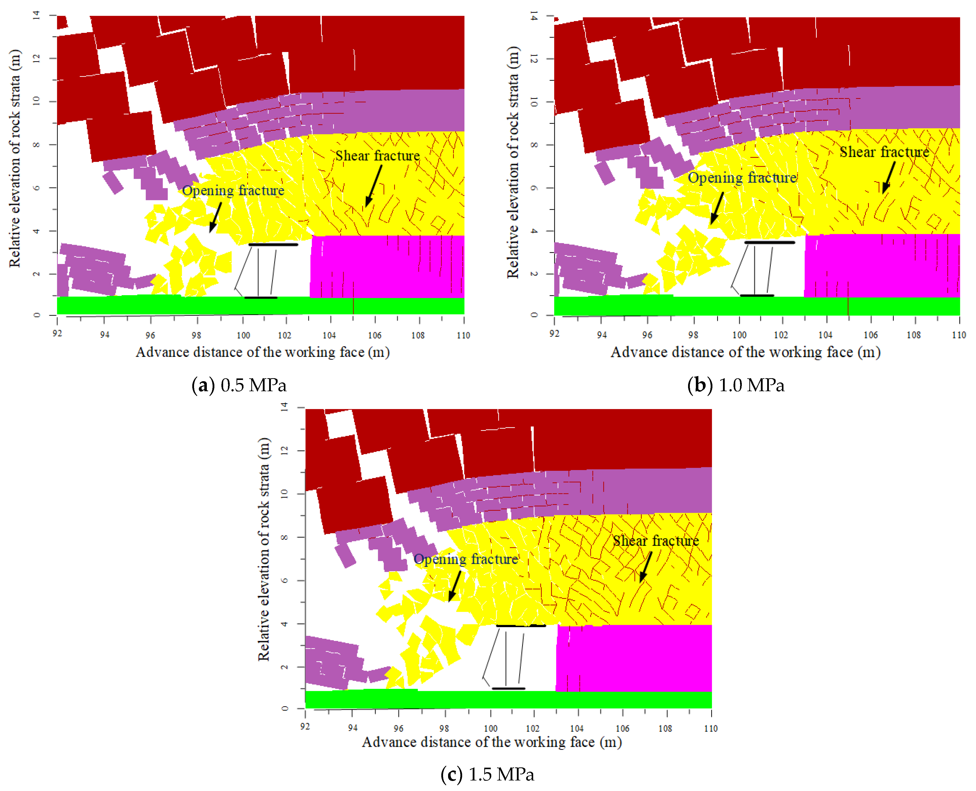
2.3. Crack Propagation Pattern in the Support Disturbance Zone

In front of the working face, the inlaid blocks can be regarded as being in a state of static equilibrium. After the coal body below is excavated, the top coal at the boundary may slide along a structural plane, breaking the equilibrium state of the block structure of the top coal and causing consecutive instability of the blocks. The caving of top coal behind the support is a natural migration process following the instability of the blocks, and the instability of the block structure is crucial for the smooth caving of the top coal.
Due to the different orientations of mining-induced fractures, the resulting block structures also vary. The blocks can be classified into finite blocks and infinite blocks based on whether they are completely surrounded by fractures. Infinite blocks refer to blocks that are not completely isolated by fractures and where at least part of them is connected to other blocks. These blocks are considered stable and require a significant force to separate them from the parent body. Finite blocks, on the other hand, are isolated by boundaries and fractures. Depending on their stability, they can be further subdivided into movable blocks and immovable blocks. Immovable blocks are constrained in all directions and can only become unstable after the neighboring blocks lose stability. Movable blocks, based on their likelihood of instability, can be further divided into three subcategories: stable blocks, potentially unstable blocks, and key blocks. The basic types of blocks are shown in Figure 3. Stable blocks can remain stable under their own weight; potentially unstable blocks will become unstable when the force along the structural plane due to gravity and external forces exceeds the friction between the blocks; key blocks become unstable under their own weight when one side is exposed.
According to the theory of block instability, combined with the block structure characteristics in the process of top-coal failure, the failure of top coal can be described in three stages: the axial loading and lateral unloading stage, the initial support stage, and the support disturbance stage.
The axial loading and lateral unloading stage occurs in front of the working face. The peak point of axial loading is the peak point of the abutment pressure. During this stage, the fractures within the coal body mainly expand in the vertical joint direction and close in the horizontal direction, while the inclined joints primarily experience shear slip. When these expanding fractures interconnect, they form large failure surfaces locally. The fracture propagation pattern is illustrated in Figure 4.
During the initial support stage, the roof continuously subsides with a certain curvature along the advancing direction. Meanwhile, the support applies an initial supporting force to the top coal. The block structure that is formed in the post-peak deformation zone of the coal body undergoes uncoordinated deformation under the initial compression of the roof and the support, leading to the dislocation and opening of the block structure. According to the theory of block instability, the forms of failure occurring in the top coal above the support during the initial support stage can be summarized as inter-block breakage, inter-block opening, intra-block fracture development, and intra-block sliding, as shown in Figure 5.
Inter-block breakage and inter-block opening mainly occur along the fracture surfaces formed in the post-peak deformation zone. These two forms of failure will occur above the support beam regardless of the coal body strength. However, whether a intra-block fracture redevelops and intra-block sliding occurs, the extent of their development depends on the coal body strength.
When the coal body strength is low, the block structure in the post-peak deformation zone is not evident, and the internal fractures of the coal body are evenly distributed, making the deformation of the coal body appear continuous and mainly exhibiting overall failure. At this stage, the coal body can be crushed into smaller blocks under relatively small compressive forces, manifesting as the forms (c) and (d) of failure. Since the coal body is fully fragmented after experiencing the post-peak deformation stage and the initial support stage when the coal body strength is low, further fragmentation by support disturbance is unnecessary. Under these conditions, the main concern in fully mechanized caving faces is to prevent roof falls in front of the supports and damage to the supports due to uneven loading.
When the coal body strength is high, the amount of roof subsidence during the initial support stage is small, and the development of fractures within the block structure of the coal body is limited. The failure of forms (c) and (d) only occurs in localized areas, and the block size of the fragmented coal is generally consistent with or smaller than the fracture network size in the post-peak deformation zone, failing to meet the size requirements of the coal discharge opening. Therefore, it is necessary to rely on the continued subsidence of the roof and the larger compressive force formed by the combined action of the roof and the support to further fragment the coal body.
During the support lifting and lowering disturbance stage, the subsidence speed of the roof increases, and the amount of subsidence continues to grow, gradually increasing the compressive force on the coal body. The fractures within the blocky coal body extend under the compressive force until they become interconnected, predominantly manifesting as vertical or steeply inclined fractures. Simultaneously, the embedded blocks slide against each other, as shown in Figure 6a,b.
At this stage, the factors influencing the degree of blocky coal body failure include the subsidence speed of the roof and the support force of the support system. To achieve more uniform fragmentation of the blocky coal body, repeated loading and unloading of the top coal can be achieved by raising and lowering the support beam. After the support beam is lowered, the loose blocks settle and rotate under their own weight. Reapplying the load can relatively change the force direction on the blocky coal, making the degree of fragmentation consistent in all directions, as shown in Figure 6c.
The core of block mechanics problems lies in calculating all possible sliding blocks given the known structural surface orientations and mechanical parameters, thereby further using mechanics and block motion theories to determine the instability of the key blocks. The UDEC 6.0 software, which uses triangular Trigon elements as the basic block units, can more realistically simulate the block instability process. Moreover, by creating excavation models with the UDEC 6.0 software, the structural surface orientations and mechanical properties of the coal body subjected to mining-induced stress can be obtained, allowing for a more precise analysis of the instability process of the blocky top coal in the support control area.

2.4. Calculation Methods for Coal Strength

The strength of the coal body depends on the strength of the intact blocks within the coal and the strength of the structural weak planes. Reference [33] proposed a relationship between rock strength and rock mass strength based on the rock quality designation (RQD) as a conversion basis. According to the proposed rock mass strength calculation method, the elastic modulus Em of the coal body can be obtained from the following formula:
E m E r = 10 0.0186 RQD 1.91
Here, Er is the elastic modulus of the intact rock, which is 1.17 GPa. According to the description of the joint orientation within coal bodies of different strengths presented in reference [34], the quality index for soft coal is set at 73. The elastic modulus Em of the coal body is calculated to be 0.33 GPa.
According to the rock mass strength calculation method proposed in reference [35], the uniaxial compressive strength σcm of the rock mass is related to the elastic modulus Em of the rock mass by the following relationship:
σ cm σ c = E m E r
Here, σc represents the uniaxial compressive strength of intact rock, which is 11.1 MPa. By substituting the known parameters, σcm can be calculated as 3.1 MPa. Numerous laboratory coal mechanics experiments indicate that the tensile strength of rocks is approximately 0.1 to 0.125 times the uniaxial compressive strength. For this paper, the tensile strength of rocks σtm is taken as 0.31 MPa. Similarly, the mechanical parameters of medium-hard and hard coal bodies can be calculated, as shown in Table 1.

3. Analysis of the Roof Coal Failure Process in the Caving Mining Support Control Zone

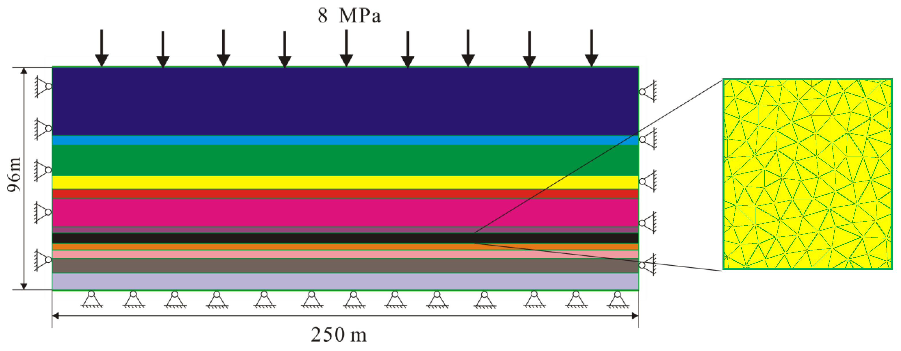
3.1. Numerical Model

In order to study the failure patterns of coal bodies ahead of the mining face under different coal strengths, numerical models are established for three types of coal seams: soft coal, medium-hard coal, and hard coal. Due to the limited range of the roof being controlled by the hydraulic support, its impact on the subsidence of the upper roof is minimal. In this simulation, three levels of support pressure are set, 0.5 MPa, 1.0 MPa, and 1.5 MPa, to study the failure characteristics of the top coal above the support in the mining face under these three conditions.
Using the 8935 working face of the Xinzhou Yao Coal Mine as the background, the lithological characteristics of the coal seam roof and floor are shown in Figure 7. Based on the “three-zone” characteristics revealed by the borehole television imaging system, a two-dimensional UDEC model with a length of 250 m, height of 96 m, and horizontal strata is constructed. The coal seam thickness is set to 8.0 m, with a direct roof thickness of 2 m, a main roof thickness of 27 m, and a direct floor thickness of 5 m. The dip angle of the strata is set to 0°, and the specific model is shown in Figure 8. The excavation height of the working face is set to 3 m, the caving height is 5 m, and the mining-to-caving ratio is 1:1.67.
The main focus of the numerical model is the failure process of the top coal, which requires refining the block size of the top coal. To simulate the instability process of the top coal in the support-controlled area, Trigon triangular random blocks are used for the top coal. Considering the gradual coupling of block size with the roof and floor, the average diameter of the Trigon blocks is set to 0.5 m. The specific physical and mechanical parameters of the three types of coal strength used in the numerical simulation are shown in Table 1.
For the immediate roof and main roof, the simulation needs to reflect the characteristics of the immediate roof collapsing as mining progresses and the periodic failure characteristics of the main roof. To coordinate with the block size of the top coal, the size of the immediate roof blocks is set at 1 m in height and 2 m in length, while the main roof blocks are set at 3 m in height and 5 m in length. For other overlying strata, their main function is to provide an overburden load. To avoid computational errors due to deformation after block failure, the cohesive strength of the blocks in the other overlying strata is set to a relatively high value.
Based on the rock mechanics experiments conducted on samples from the 8935 working face, repeated adjustments through numerical simulation were made to determine the physical parameters of each stratum used in the simulation, as shown in Table 2 and Table 3.

3.2. Methods of Applying Ground Stress and Support Disturbance Schemes

3.2.1. Application of Ground Stress

Based on the distribution of self-weight stress in the rock mass, a pressure P is applied to the upper boundary of the model to simulate the self-weight load of the upper rock layers. The pressure is calculated as: P = γ·H = 2500 × 10 × 367 Pa = 9.175 MPa. According to the in situ stress test results of the Xinzhou Yao Mine documented in reference [36], the lateral pressure coefficient of the 8935 working face is approximately 1.25. The process of applying ground stress to the model is carried out in two steps as follows:

Elastic Model Initialization

The entire model adopts an elastic model, with the elastic modulus of the model units assigned a large value, E = 1.0 × 10¹² Pa. Apply a boundary stress of 13.75 MPa to the bottom of the left and right sides of the model. The boundary stress decreases from the bottom to the top, with a gradient of 31,250 Pa/m. Apply vertical constraints to the bottom boundary of the model. All units in the model are to be assigned vertical stress, increasing from top to bottom at a gradient of 25,000 Pa/m, and horizontal stress, increasing at a gradient of 31,250 Pa/m. Solve to obtain the ground stress model.

Parameter Reassignment and Constitutive Models

Reassign the parameters to the rock mass in the solved model. The physical and mechanical parameters of the rock layers are shown in Table 2, and the mechanical parameters of the joints are shown in Table 3. Use the Mohr–Coulomb model for the rock layers and the Coulomb slip model for the joints. Reset the displacements and velocities of all units in the model to zero from the first stage. At this point, the model is established and can be excavated according to the research requirements.

3.2.2. Excavation and Support Disturbance Scheme

After initializing the ground stress and assigning the parameters to the model, begin stepwise excavation: Excavate 5 m per step until the initial fracture of the main roof in the mining area. Subsequently, excavate 2 m per step until reaching the mesh refinement area. At this stage, the top coal above the support beam has already undergone the stage of bearing the support pressure. The subsequent stages mainly involve the initial support stage and repeated disturbance from the raising and lowering of the support beam, affecting coal breakage. To study the failure process of the coal body in detail during these two stages, different support disturbance methods are used, which are divided into three steps:

Coal in the Coal Wall Support Area

The top coal is still in the coal wall support area, bearing continuous compressive force during the roof subsidence process. The degree of compression varies with the extent of roof subsidence.

Initial Support Stage

The initial support force of the support is relatively small. As the roof continues to subside, the top coal also subsides. Depending on the initial support force of the support, the subsidence amount ranges from approximately 50 to 500 mm.

Support Beam Disturbance Stage

During continuous roof subsidence, apply active support force to the top coal by raising the support beam. The support beam can be adjusted multiple times to repeatedly disturb the top coal, which is based on the extent of coal body failure.

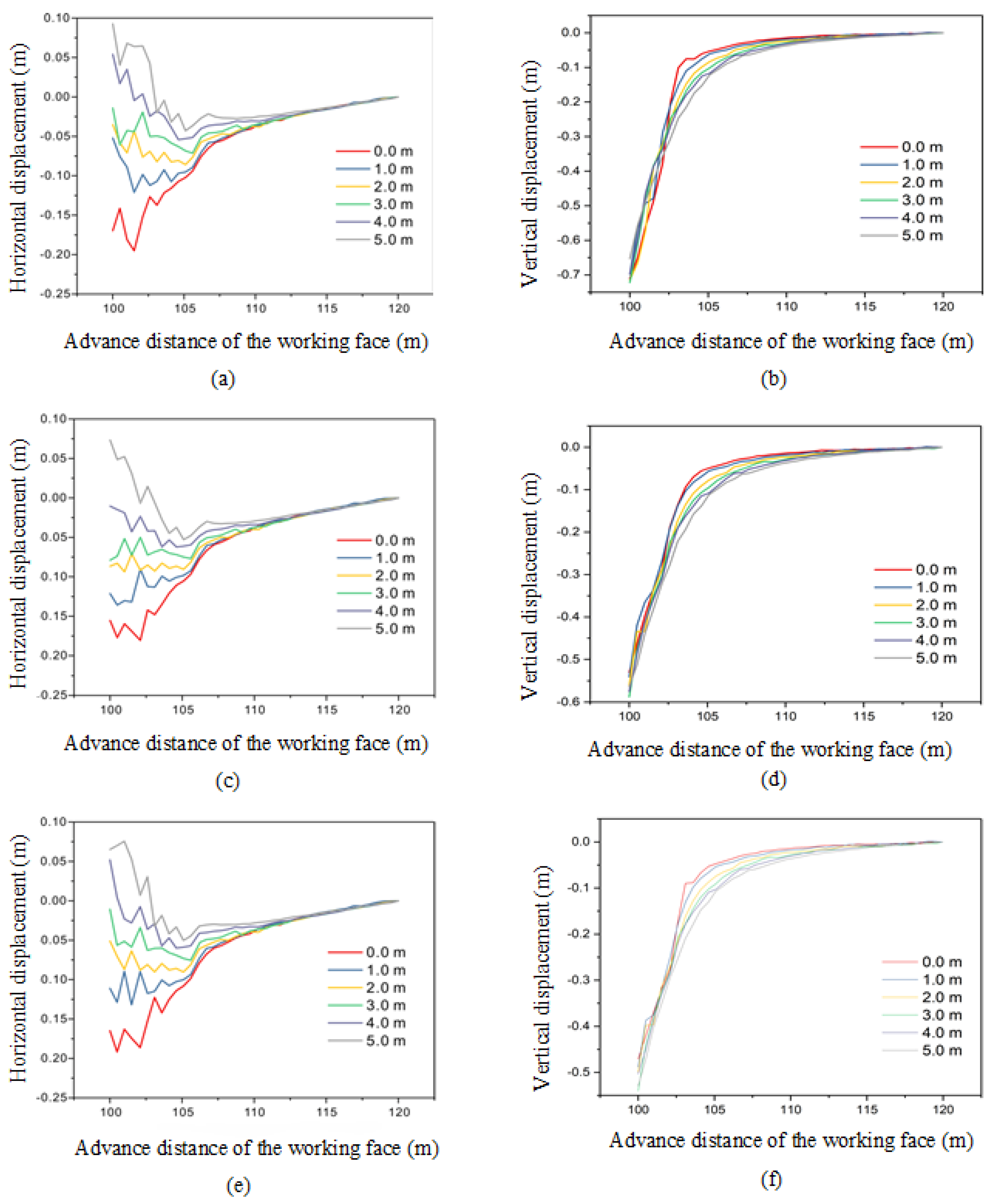
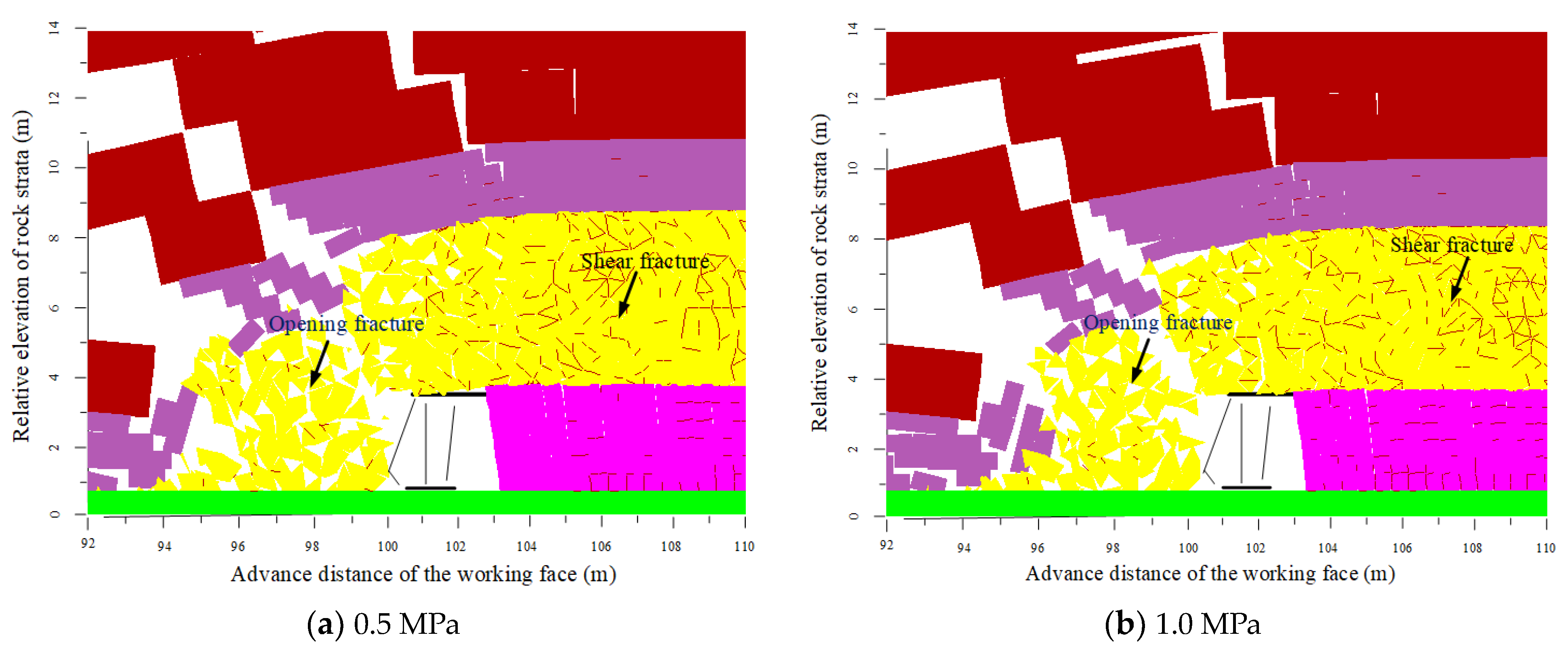
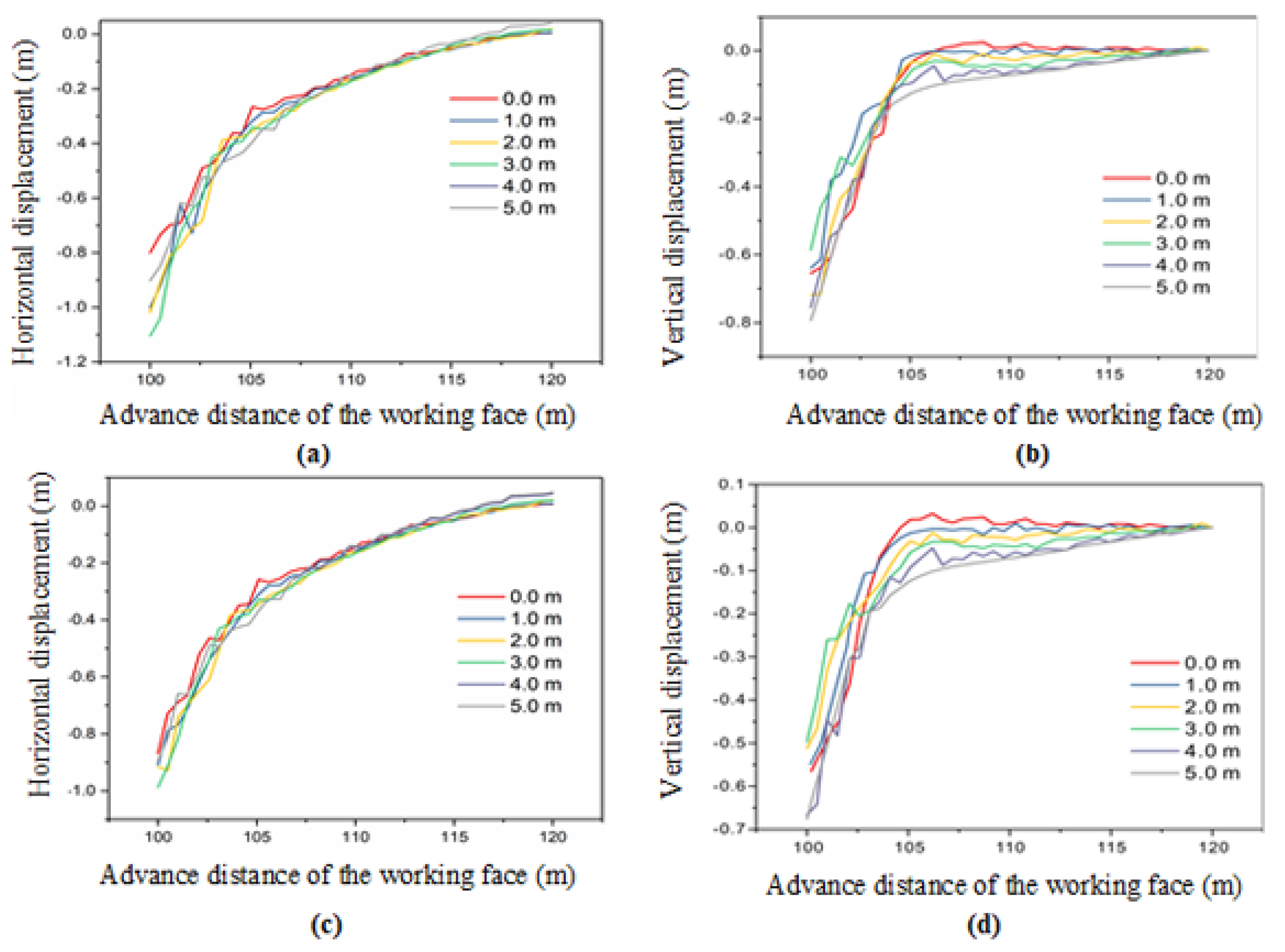
3.3. Initial Support Phase of the Bracket

In this stage, three different support strengths of 0.5 MPa, 1.0 MPa, and 1.5 MPa were set to observe the deformation characteristics of the coal bodies with strengths of 15 MPa and 29.5 MPa, as well as the deformation characteristics of the coal bodies with a strength of 3.1 MPa when the support strengths were 0.5 MPa and 1.0 MPa. To enhance the comparability of the results, the advancement distance of the working face in this stage was uniformly set to 103 m, and the damage to the top coal under the influence of the surrounding rock in the mining area and the support was observed.
Figure 9 shows the damage to the coal body with a strength of 29.5 MPa under different support strengths. It can be seen that due to the high strength of the coal body after the lower coal seam is excavated, a large number of cracks are generated within the suspended top coal, but the top coal is not completely damaged and cannot collapse immediately after mining. Instead, it forms a suspended structure, with the top coal still remaining in an overall structure. The horizontal deformation of the top coal shows little difference under the three support strengths, while the vertical displacement decreases with the increase in support strength, as shown in Figure 10. It is evident that when the coal body strength is high, the top coal is not easily collapsed, and certain measures need to be taken to weaken the coal body.
The failure patterns of the top coal with a coal body strength of 15 MPa under different support forces are shown in Figure 11. It can be seen that at this strength, the coal body generally collapses following the excavation of the lower coal seam. When the support force of the support is relatively small, the subsidence amount of the top coal above the canopy is larger, and the relative sliding displacement of the block-structured top coal is greater. Adjacent blocks break and dislocate along the horizontal direction. As the support force increases, the subsidence amount of the top coal shows a decreasing trend. The increase in support force restricts the vertical dislocation between blocks, reducing the number of unstable blocks in the top coal. The deformation curves in Figure 12 indicate that as the support force increases, the horizontal displacement of the top coal slightly decreases.
Under all three support forces, most of the fractures within the top coal have penetrated. When the support force is 0.5 MPa, all the fractures above the canopy are tensile fractures, and the sliding fractures in front of the support also open up after the lateral constraint decreases. As the support force increases, shear fractures gradually appear above the canopy, with the most noticeable increase in shear fractures occurring in the coal body in front of the support. The top coal above the support is mainly a mosaic of block structures. Some loose mosaic structures can gradually become unstable and break into smaller blocks during the collapse process, while some remain as large blocks requiring manual intervention for handling. The vertical fractures in the top coal have the greatest aperture, mainly forming several elongated strips in the vertical direction. At this time, applying axial compressive force to the top coal to break the elongated coal bodies can effectively increase the number of unstable blocks.
The failure patterns and deformation of the coal body with a strength of 3.1 MPa under the action of the support and surrounding rock are shown in Figure 13 and Figure 14. Due to the low strength of the coal body, the vertical deformation of the coal body above the support is large, causing the roof to sink and break above the support. The horizontal displacement of the coal body is significant due to the compressive force from the roof. In the early stages of top-coal caving, the horizontal displacement of the top coal is greater than the vertical displacement. As shown in Figure 13, the top coal in front of the working face is already unstable, and the coal body above the support canopy is sufficiently fractured and in a loose state. As the support advances, the top coal can cave in on its own, forming small blocks. Because the coal body above the support is fractured, the support force of the support is absorbed by the fractured top coal, resulting in poor roof control effectiveness by the support. In this situation, special attention should be paid to roof falls at the canopy end and the impact of roof breaks on the support.

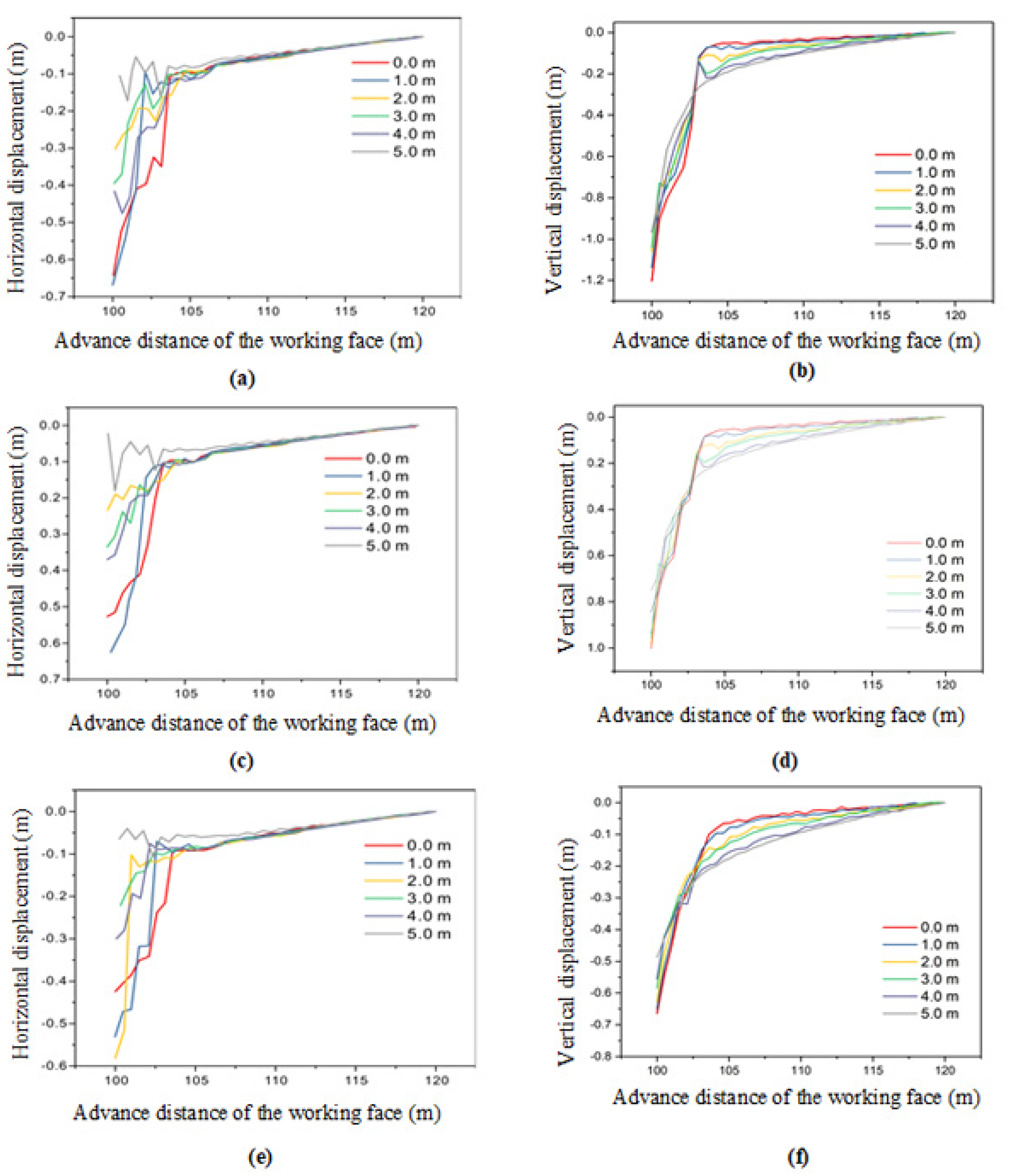
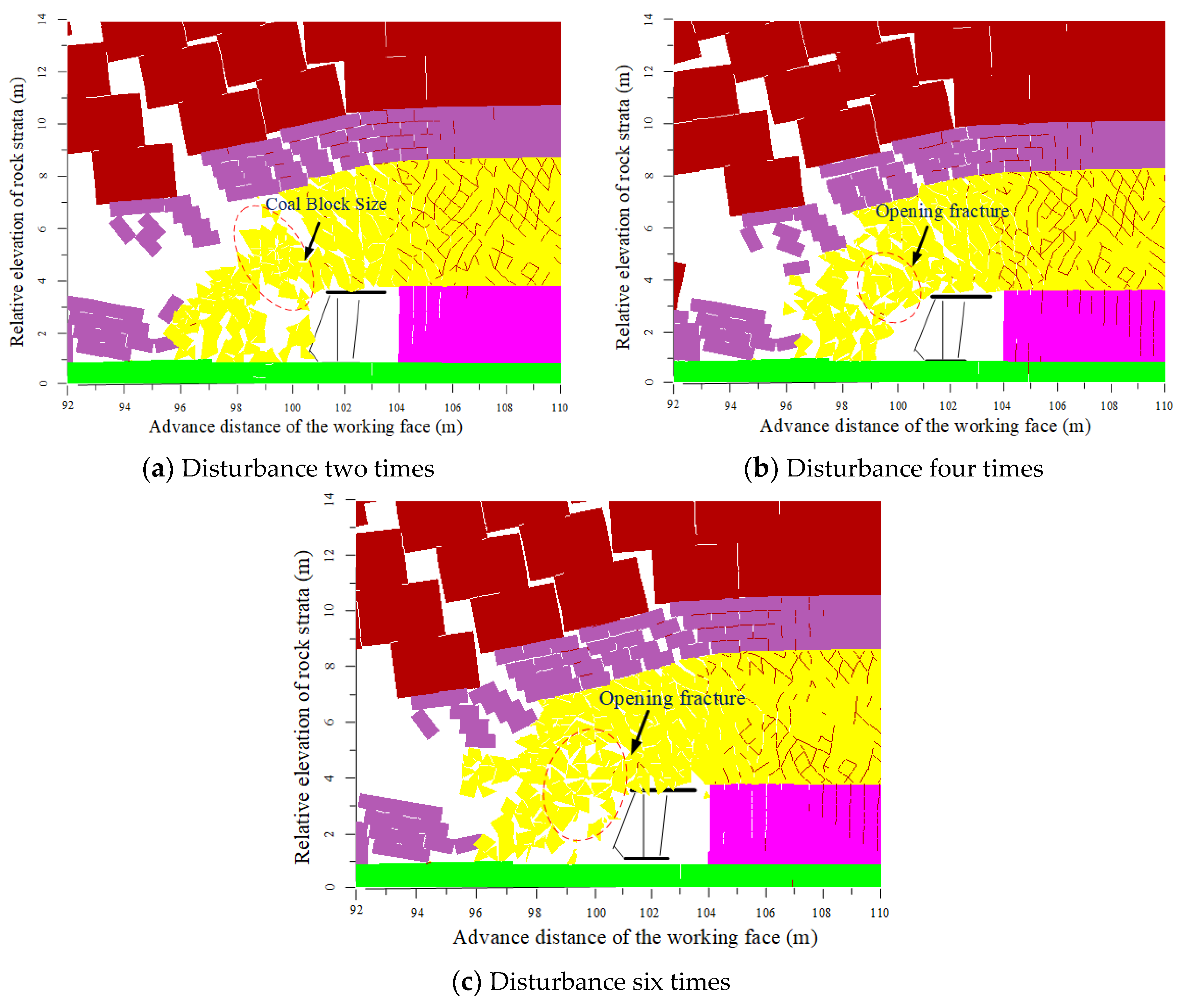
3.4. Support Cyclic Disturbance Stage

In actual production, the top coal is generally disturbed during the movement of the support. Depending on the size of the coal fragments, multiple disturbances can be applied. For coal bodies with a strength of 15.0 MPa, a supporting force of 1.0 MPa can be used to disturb the support 2, 4, and 6 times, respectively. During the disturbance process, the support moves forward a total of 1.0 m, with disturbances occurring once, twice, and three times, respectively, for every 0.5 m of forward movement. The characteristics of the top-coal failure after implementing the three disturbance schemes are shown in Figure 15. After experiencing disturbances, the previously formed vertical elongated coal blocks become unstable under the extrusion of the canopy and the roof, breaking into several small blocks. Under two disturbances, the size of the broken blocks remains relatively large. As the number of disturbances increases, the size of the broken blocks becomes progressively smaller. This is because, with the increase in the number of disturbances, the advancement speed of the working face relatively decreases, the amount of roof subsidence relatively increases, and the continuous extrusion of the roof increases the horizontal deformation of the coal body, consequently raising the probability of block instability. On the other hand, an increase in the number of cyclic disturbances can repeatedly loosen the block-structured top coal, increasing the number of unstable blocks. Therefore, in actual production, it is advisable to appropriately reduce the advancement speed of the working face and use smaller support moving steps to increase the number of repeated disturbances by the support canopy in the same area, thereby enhancing the effect of disturbance-induced coal fragmentation.

4. Conclusions

Regarding the disturbance relationship between the hydraulic support and the top coal in a fully mechanized caving face, this study focused on the active destruction effect of the hydraulic support’s top beam on the upper top coal. The main conclusions are as follows:
(1) The failure of the top coal above the support canopy can be divided into two distinct stages: the initial support stage and the support lifting disturbance stage. In the initial support stage, the supporting body beneath the top coal transitions from solid coal to a support frame, which induces vertical deformation of the top coal due to the influence of the roof. This deformation inconsistency leads to several primary failure modes in the coal body, including block inter-fracture, block inter-separation, and intra-block fractures. In this stage, the initial supporting force of the support has little influence on the fragmentation degree of the top coal. During the lifting disturbance stage, the top coal is subjected to compressive and tensile failures due to the extrusion pressure from the support canopy and the roof, with the main failure modes including block inter-sliding and inter-rotation.
(2) In the support-controlled area, the top coal with a mosaic structure still retains high strength in small blocks. During the support disturbance process, the support primarily promotes the separation of weak bonding surfaces between blocks rather than the failure of high-strength small blocks. For hard coal bodies, the supporting force of the support is much lower than the overall strength of the top coal after a mining disturbance; thus, the support disturbance has a minimal effect on the fragmentation of the top coal.
(3) The extrusion–unloading–extrusion cyclic action between the roof and the support canopy on the top coal promotes a continuous increase in lateral displacement of the block-structured coal body. The greater the active supporting force of the support, the more likely the block-structured coal body is to become unstable along the weaker surfaces, resulting in larger separated block sizes. A smaller supporting force, suitable for the coal body’s strength, combined with multiple disturbances, can constantly change the stress direction of the block-structured coal body, promoting balanced development along internal weak surfaces and increasing the probability of block instability, making it more suitable for support disturbance-induced coal fragmentation. In actual production, increasing the number of disturbances to the top coal within the cycle’s progress can improve the top-coal fragmentation effect.

Author Contributions

Each author has contributed to the present paper. C.Z., D.H., and J.Y. conceived and designed the experiments; S.Y., L.C., and Z.L. performed the experiments and analyzed the experimental data; J.Z. drafted the manuscript; P.D., H.W., and J.Z. revised the manuscript. All authors have read and agreed to the published version of the manuscript.

Funding

This work is supported by the National Natural Science Foundation of China (No. 52374110), the Key Scientific and Technological Projects of Henan Province (No. 242102320337), and the Basic Research Fund of Zhongyuan University of Technology (No. K2022QN008).

Data Availability Statement

The original contributions presented in the study are included in the article, further inquiries can be directed to the corresponding author.

Conflicts of Interest

Author Jianjian Zhao was employed by the company Zimasco Private Limited. The remaining authors declare that the research was conducted in the absence of any commercial or financial relationships that could be construed as a potential conflict of interest. The company had no role in the design of the study; in the collection, analyses, or interpretation of data; in the writing of the manuscript, or in the decision to publish the results.

References

  1. Dang, J.; Tu, M.; Zhang, X.; Bu, Q. Research on the bearing characteristics of brackets in thick hard roof mining sites and the effect of blasting on roof control. Geomech. Geophys. Geo-Energy Geo-Resour. 2024, 10, 18. [Google Scholar] [CrossRef]
  2. Arif, Ç.; Yılmaz, Ö. Investigation of the efficiency of longwall top coal caving method applied by forming a face in horizontal thickness of the seam in steeply inclined thick coal seams by using a physical model. Int. J. Rock Mech. Min. Sci. 2021, 148, 104917. [Google Scholar] [CrossRef]
  3. Guo, J.; Huang, W.; Feng, G.; Bai, J.; Li, L.; Wang, Z.; Yu, L.; Wen, X.; Zhang, J.; Feng, W. Stability analysis of longwall top-coal caving face in extra-thick coal seams based on an innovative numerical hydraulic support model. Int. J. Min. Sci. Technol. 2024, 34, 491–505. [Google Scholar] [CrossRef]
  4. Liang, Y.; Ran, Q.; Zou, Q.; Zhang, B.; Hong, Y. Experimental Study of Mechanical Behaviors and Failure Characteristics of Coal Under True Triaxial Cyclic Loading and Unloading and Stress Rotation. Nat. Resour. Res. 2022, 31, 971–991. [Google Scholar] [CrossRef]
  5. Kong, D.; Cheng, Z.; Zheng, S. Study on the failure mechanism and stability control measures in a large-cutting-height coal mining face with a deep-buried seam. Bull. Eng. Geol. Environ. 2019, 78, 6143–6157. [Google Scholar] [CrossRef]
  6. Xue, J.; Zhao, T. Deformation and Fracture Characteristics of Coal Gangue Interbedded Samples under Loading and Unloading Conditions. Adv. Civ. Eng. 2022, 10, 1.1–1.12. [Google Scholar] [CrossRef]
  7. Han, P.; Zhang, C.; He, X.; Wang, X.; Qiao, Y. DEM fluid–solid coupling method for progressive failure simulation of roadways in a fault structure area with water-rich roofs. Geomech. Geophys. Geo-Energy Geo-Resour. 2022, 8, 194. [Google Scholar] [CrossRef]
  8. Deng, G.; Xie, H.; Gao, M.; Li, C.; He, Z. Numerical Simulation on the Evolution of Mining-Induced Fracture Network in a Coal Seam and Its Overburden under the Top Coal Caving Method. Adv. Civ. Eng. 2020, 2020, 8833193. [Google Scholar] [CrossRef]
  9. Wang, J.; Wang, Z.; Li, Y. Longwall Top Coal Caving Mechanisms in the Fractured Thick Coal Seam. Int. J. Geomech. 2020, 20, 06020017. [Google Scholar] [CrossRef]
  10. Song, Z.; Konietzky, H.; Herbst, M. Drawing mechanism of fractured top coal in longwall top coal caving. Int. J. Rock Mech. Min. Sci. 2020, 130, 104329. [Google Scholar] [CrossRef]
  11. Wei, W.; Yang, S.; Li, M.; Zhang, J.; Wei, C. Motion Mechanisms for Top Coal and Gangue Blocks in Longwall Top Coal Caving (LTCC) with an Extra-Thick Seam. Rock Mech. Rock Eng. 2022, 55, 5107–5121. [Google Scholar] [CrossRef]
  12. Wang, F.; Xie, H.; Zhou, C.; Wang, Z.; Li, C. Combined effects of fault geometry and roadway cross-section shape on the collapse behaviors of twin roadways: An experimental investigation. Tunn. Undergr. Space Technol. 2023, 137, 105106. [Google Scholar] [CrossRef]
  13. Liang, Y.; Li, L.; Li, X.; Wang, K.; Chen, J.; Sun, Z.; Yang, X. Study on Roof-Coal Caving Characteristics with Complicated Structure by Fully Mechanized Caving Mining. Shock. Vib. 2019, 2019, 6519213. [Google Scholar] [CrossRef]
  14. Gao, F.; Lv, S.; Zhang, C.; Zhang, P.; Guo, Z.; Ma, Q.; Zhang, X. Discrete- and Finite-Element Analysis on the Tunneling Safety of Pipe Jacking Machine in Coal Rock Formation. Int. J. Heat Technol. 2020, 38, 801–807. [Google Scholar] [CrossRef]
  15. Nan, H.; Wang, S. Migration law of different top coal thicknesses in top coal caving. Front. Earth Sci. 2022, 10, 999979. [Google Scholar] [CrossRef]
  16. Tian, C.; Wang, A.; Liu, Y.; Jia, T. Study on the Migration Law of Overlying Strata of Gob-Side Entry Retaining Formed by Roof Cutting and Pressure Releasing in the Shallow Seam. Shock. Vib. 2020, 2020, 8821160. [Google Scholar] [CrossRef]
  17. Xue, B.; Zhang, W.; Wang, C. Determination of working resistance of support parameter variation of large mining height support: The case of Caojiatan coal mine. Geomech. Geophys. Geo-Energy Geo-Resour. 2024, 10, 1. [Google Scholar] [CrossRef]
  18. Liu, H.; Dai, J.; Jiang, J.; Wang, P.; Yang, J. Analysis of Overburden Structure and Pressure-Relief Effect of Hard Roof Blasting and Cutting. Adv. Civ. Eng. 2019, 2, 1354652. [Google Scholar] [CrossRef]
  19. Guo, Z.; Mou, W.; Huang, W.; Duan, H. Analysis on Roadside Support Method with Constant Resistance Yielding-Supporting Along the Goaf Under Hard Rocks. Geotech. Geol. Eng. 2016, 34, 827–834. [Google Scholar] [CrossRef]
  20. Wang, K.; Zhao, T.; Yetilmezsoy, K.; Zhang, X. Cutting-Caving Ratio Optimization of Fully Mechanized Caving Mining with Large Mining Height of Extremely Thick Coal Seam. Adv. Civ. Eng. 2019, 2019, 7246841. [Google Scholar] [CrossRef]
  21. Yue, X.; Tu, M.; Li, Y.; Chang, G.; Li, C. Stability and Cementation of the Surrounding Rock in Roof-Cutting and Pressure-Relief Entry under Mining Influence. Energies 2022, 15, 951. [Google Scholar] [CrossRef]
  22. Wang, J.; Yang, S.; Wei, W.; Zhang, J.; Song, Z. Drawing mechanisms for top coal in longwall top coal caving (LTCC)_ A review of two decades of literature. Int. J. Coal Sci. Technol. 2021, 8, 1171–1196. [Google Scholar] [CrossRef]
  23. Vu, T. Solutions to prevent face spall and roof falling in fully mechanized longwall at underground mines. Min. Miner. Depos. 2022, 12, 127–134. [Google Scholar] [CrossRef]
  24. Dyczko, A.; Malec, M.; Prostanski, D. The efficiency of longwall systems in the case of using different cutting technologies in the LW Bogdanka. Acta Montan. Slovaca 2020, 25, 504–516. [Google Scholar] [CrossRef]
  25. Ma, B.; Xie, H.; Zhou, C.; Zhou, H.; Gao, F.; Cao, P.; Zhu, J. Experimental investigation into influence of surrounding rock on strainburst: Insight from failure process and energy partition. Int. J. Rock Mech. Min. Sci. 2024, 175, 105685. [Google Scholar] [CrossRef]
  26. Zhang, J.; Jiang, Y.; Li, B.; Guo, J.; Lu, W.; Qu, L. Modeling and coupling analysis of enhanced coalbed methane recovery by gas injection. Int. J. Numer. Anal. Methods. Geomech. 2024, 48, 1931–1948. [Google Scholar] [CrossRef]
  27. Guo, W.; Li, Y.; Wang, G. The Instability Characteristics and Displacement Law of Coal Wall Containing Joint Fissures in the Fully Mechanized Working Face with Great Mining Height. Energies 2022, 15, 9059. [Google Scholar] [CrossRef]
  28. Xie, S.; Wu, Y.; Ma, X.; Chen, D.; Guo, F.; Jiang, Z.; Li, H.; Zou, H.; Liu, R.; Zhang, X. Reasonable stopping method and retracement channel support at fully mechanized top coal caving working face of 15 m extra-thick coal seam: A case study. Energy Sci. Eng. 2022, 10, 4336–4357. [Google Scholar] [CrossRef]
  29. Zeng, Q.; Li, Z.; Wan, L.; Ma, D. Study on Roof Instability Effect and Bearing Characteristics of Hydraulic Support in Longwall Top Coal Caving. Appl. Sci. 2023, 13, 8102. [Google Scholar] [CrossRef]
  30. Le, T.; Bui, X. Effect of Key Parameters on Top Coal First Caving and Roof First Weighting in Longwall Top Coal Caving: A Case Study. Int. J. Geomech. 2020, 20, 04020037. [Google Scholar] [CrossRef]
  31. Cao, L.; Jin, X.; Qin, J.; Zhang, X.; Gao, L. Research on the hydraulic support top beam based on dynamic load bearing. Front. Earth Sci. 2023, 11, 1171342. [Google Scholar] [CrossRef]
  32. Wang, J.-A.; Yang, L.; Li, F.; Wang, C. Force chains in top coal caving mining. Int. J. Rock Mech. Min. Sci. 2020, 127, 104218. [Google Scholar] [CrossRef]
  33. Zhang, L.; Einstein, H. Using Rqd to Estimate the Deformation Modulus of Rock Masses. Int. J. Rock Mech. Min. Sci. 2004, 41, 337–341. [Google Scholar] [CrossRef]
  34. Wei, P.; Liang, Y.; Zhao, S.; Peng, S.; Li, X.; Meng, R. Characterization of Pores and Fractures in Soft Coal from the No. 5 Soft Coalbed in the Chenghe Mining Area. Processes 2019, 7, 13. [Google Scholar] [CrossRef]
  35. Mahendra, S.; Rao, K. Empirical Methods to Estimate the Strength of Jointed Rock Masses. Eng. Geol. 2005, 77, 127–137. [Google Scholar] [CrossRef]
  36. Chi, M.; Tang, H.; Liu, D.; Wang, D.; Dai, C.; Zou, J.; Gao, Q.; Feng, G. Study of hydraulic cutting as a method to prevent coal burst disasters. Heliyon 2024, 10, e30679. [Google Scholar] [CrossRef]
Figure 1. Blocks shape of hard coal mass around the support. (a) The cantilever structure on the top beam of the support. (b) Large coal blocks falling behind the support.
Processes 12 01872 g001
Figure 2. Initial support phase of top-coal caving mining face.
Processes 12 01872 g002
Figure 3. Types of blocks.
Processes 12 01872 g003
Figure 4. Fracture evolution of coal mass at front abutment zone. (a) Tensile fracture. (b) compression fracture. (c) shear fracture.
Processes 12 01872 g004
Figure 5. Fracture patterns of coal mass at initial support phase. (a) Inter-block fracture. (b) Inter-block delamination. (c) Internal crack extension. (d) Inter-block sliding.
Processes 12 01872 g005
Figure 6. Fracture patterns of coal mass under recycle loading of support. (a) Inter-block sliding. (b) Internal crack extension. (c) Inter-block rotation.
Processes 12 01872 g006
Figure 7. Rock strata around No. 11 and 12 coal seams of main roof.
Processes 12 01872 g007
Figure 8. UDEC model for excavation of top-coal caving mining face.
Processes 12 01872 g008
Figure 9. Fracture pattern of 29.5 MPa coal mass under various supporting intensities.
Processes 12 01872 g009aProcesses 12 01872 g009b
Figure 10. Strain of 29.5 MPa coal mass under various supporting intensities. (a) Horizontal displacement at a support strength of 0.5 MPa; (b) vertical displacement at a support strength of 0.5 MPa; (c) horizontal displacement at a support strength of 1.0 MPa; (d) vertical displacement at a support strength of 1.0 MPa; (e) horizontal displacement at a support strength of 1.5 MPa; (f) vertical displacement at a support strength of 1.5 MPa.
Processes 12 01872 g010
Figure 11. Fracture patterns of 15 MPa coal mass under various supporting intensities.
Processes 12 01872 g011
Figure 12. Strain of 15 MPa coal mass under various supporting intensities. (a) Horizontal displacement at a support strength of 0.5 MPa; (b) vertical displacement at a support strength of 0.5 MPa; (c) horizontal displacement at a support strength of 1.0 MPa; (d) vertical displacement at a support strength of 1.0 MPa; (e) horizontal displacement at a support strength of 1.5 MPa; (f) vertical displacement at a support strength of 1.5 MPa.
Processes 12 01872 g012
Figure 13. Fracture patterns of 3.1 MPa coal mass under various supporting intensities.
Processes 12 01872 g013
Figure 14. Strain of 3.1 MPa coal mass under various supporting intensities. (a) Horizontal displacement at a support strength of 0.5 MPa; (b) vertical displacement at a support strength of 0.5 MPa; (c) horizontal displacement at a support strength of 1.0 MPa; (d) vertical displacement at a support strength of 1.0 MPa.
Processes 12 01872 g014
Figure 15. Fracture patterns of top coal under various disturbance types.
Processes 12 01872 g015
Table 1. Microproperties for various strengths for coal mass in UDEC model.
Uniaxial Compressive Strength (MPa)3.115.029.5
Specimen elastic modulus (GPa)0.331.122.28
Density (kg/m3)140014001400
Volume modulus (GPa)0.602.134.03
Shear modulus (GPa)0.451.863.73
Normal stiffness (GPa)9509801000
Shear stiffness (GPa)740780850
Cohesion (MPa)1.34.49.1
Internal friction angle (°)243032
Tensile strength (MPa)0.52.75.65
Table 2. Microproperties of blocks in UDEC model.
TypesRock TypeThicknessDensity
(kg/m3)
Volume Modulus (GPa)Shear Modulus
(GPa)
Cohesion
(MPa)
Internal Friction Angle (°)Tensile Strength
(MPa)
Overlying strataSiltstone30.025001.331.036.61341.40
Main roofMedium-grained sandstone4.026002.031.567.06331.50
Immediate roofSiltstone2.025001.141.065.05320.9
FloorSiltstone8.025001.151.054.97320.9
Table 3. Properties for the joint of rock masses in UDEC model.
TypesNormal Stiffness (GPa)Shear Stiffness (GPa)Cohesion
(MPa)
Internal Friction Angle
(°)
Tensile Strength
(MPa)
Overlying strata2.880.984.4251.0
Main roof2.420.843.56251.0
Immediate roof1.320.892.9240.9
Floor3.22.54.8261.2
Disclaimer/Publisher’s Note: The statements, opinions and data contained in all publications are solely those of the individual author(s) and contributor(s) and not of MDPI and/or the editor(s). MDPI and/or the editor(s) disclaim responsibility for any injury to people or property resulting from any ideas, methods, instructions or products referred to in the content.

