Abstract
Currently, enterprises producing crystalline silicon are facing the formation and accumulation of large volumes of microsilica, a technogenic dusty waste formed during the melting of silicon alloys. Due to its chemical composition, this waste can be a significant raw material for metallurgical production. Therefore, this study is aimed to solve the problem of recycling microsilica. For these studies, a technology for the combined briquetting of microsilica and a carbonaceous reducing agent was developed for the production of a pilot batch of briquettes. This paper presents the results obtained from the process of testing the melting of crystalline (technical) silicon from briquetted monocharge obtained from microsilica. The tests were conducted under large-scale laboratory conditions on a 200 kVA ore-thermal furnace, where 30, 50, and 100% replacements of the traditional charge mixture with briquettes were tested. The results of this study showed that briquettes in the melting process of technical silicon can be successfully used in the range of 0 to 50%. The use of briquettes can significantly improve the technological indicators. The maximum extraction of silicon (approximately 83%) was achieved at 30% replacement. The technical and economic indicators of the process also improved. In particular, an increase in productivity was observed in comparison with tests on a traditional charge.
1. Introduction
Metallurgical-grade silicon (crystalline silicon) is a critical material used in a variety of industrial applications, including aluminum alloys, silicones, and solar panels. The key regions of silicon production include China, Russia, Brazil, the USA, Canada, and European countries. According to data from the US Geological Survey (Mineral Commodity Summaries), in 2023, approximately 4000 metric tons of metallurgical-grade silicon were produced globally, with 3000 metric tons produced in China [1]. Table 1 provides an overview of production capacities using various technologies and materials [2,3,4,5,6,7,8,9,10,11,12].

Table 1.
Overview of metallurgical silicon production capacity.
The table shows that the traditional materials for crystalline silicon production are quartz and coke (a reducing agent). Additionally, the charge includes additives such as wood chips (shavings). Technological operations in silicon production involve the preparation of the charge, its melting in a submerged arc furnace, casting of silicon, and grinding it to remove slag inclusions. Quartz as the main raw material for carbothermic silicon production must contain at least 98.0% of SiO2. Traditionally, charcoal and petroleum coke are used as reducing agents. The use of them is mainly due to their low cost and low impurity content. To loosen the charge and improve its gas permeability, wood chips are also introduced into the charge [13].
All the raw materials for silicon production must meet certain requirements for fractional composition. The use of fines smaller than 20 mm is not allowed. Their melting in the upper zone of the charge worsens the gas permeability and disrupts the furnace operation. Due to the high requirements for silicon purity, alternative raw materials have not been used in practice. However, global industrial enterprises are focusing on recycling production waste and creating comprehensive resource-saving technologies that involve the processing of waste and non-standard raw materials (dust, sludge, slag [14], etc.).
In this regard, microsilica, which is a by-product of silicon production, may become an interesting alternative to high-quality quartz for metallurgical-grade silicon production. Microsilica is a fine dust-like material comprising ultrafine, amorphous SiO2 spheres. Microsilica is formed during the reduction of high-purity quartz in electric arc furnaces at temperatures above 2000 °C [15,16,17,18,19,20]. It is predominantly used in the construction industry to enhance concrete properties, such as increased strength, frost resistance, and corrosion resistance [21,22]. However, its potential as a raw material in silicon production has largely been untapped, despite its favorable chemical composition (high content of SiO2 and low content of impurities) and the ongoing accumulation of this by-product in large quantities.
The number of publications devoted to the problem of raw materials in metallurgy has been growing in recent years. The reserves of high-grade and easily processable raw materials worldwide are steadily decreasing [23]. The use of finely dispersed materials, including industrial waste, is gaining increasing importance in metallurgy, especially in silicon production. The direct use of microsilica in ore-thermal furnaces is currently impractical due to its granulometric composition [24,25]. This poses a critical barrier to its utilization in silicon production. Therefore, the development of methods for the processing and utilizing of microsilica is a crucial task that requires further research and the implementation of innovative solutions. Some researchers have practiced the use of fine raw materials via the briquetting method. This method involves the processing of industrial dust-like waste, i.e., condensed microsilica [26,27,28]. These technologies have not been realized due to the scattering of briquettes on the top of an ore-thermal furnace during the thermal shock.
This study aimed to develop an alternative method for utilizing microsilica in the production of metallurgical-grade silicon. The proposed approach involves the briquetting of microsilica with carbonaceous reducing agents to form high-strength briquettes, enabling efficient reduction and melting in ore-thermal furnaces. Based on the close contact between the silicon oxides of microsilica and the solid carbon of carbonaceous reducing agents in the briquette, the most favorable conditions for silicon reduction and melting are achieved. Thus, deficient low-ash reducing agents can be utilized as the reducing agents for fine fractions (coal screenings), for instance, screenings of charcoal, coke, lump coal, and many other low-ash reducing agents [29]. This method not only seeks to provide an alternative source of silicon but also addresses the environmental issue of thin fraction waste accumulation.
For the first time, this study explored the incorporation of microsilica into metallurgical silicon production as briquettes. This paper shows the results of replacing the standard batch with microsilica briquettes (30, 50, and 100%). According to the proposed technological solution, it will be possible to increase the extraction of silicon during the melting of the metallurgical silicon from 65 to 75% by using the standard charge known in metallurgical practice to 80 to 90% by using briquettes.
2. Materials and Methods
Microsilica is an ultra-dispersed material. It consists of spherical particles. It is obtained during the fume cleaning process of furnaces during the production of technical-grade silicon and ferrosilicon. The primary component of this material is amorphous silicon dioxide. The microsilica produced by Tauken Temir LLP (Karaganda, Kazakhstan) was used for this study. Tauken Temir LLP is a manufacturer of technical silicon with an annual output of 23,000 tons. According to this enterprise, when one ton of silicon is melted, one ton of microsilica is captured via gas cleaning systems, and 65–70% of the silicon is extracted into the metal.
The chemical composition of the microsilica used in this study is as follows, %: SiO2—96.41; Al2O3—0.26; CaO—0.62; Fe2O3—0.64; TiO2—0.09; ZrO2—1.25; Na2O—0.03; K2O—0,02; C—0.7; and P2O5—0.03.
Microsilica is generally light to dark gray in color [18]. According to known data, particles of microsilica have an average particle size of 150 nm and a high indicator of specific surface area of typically 20 m2/g or higher [19,20]. In turn, its high specific surface area is associated with an extremely finely dispersed structure, which ensures greater reactivity in the composition of the batch mixture.
Due to its fine dispersion, direct loading of microsilica into the ore-thermal furnace is not possible. The use of a charge of such a granulometric size will entail significant dust removal and sharp changes in the heating of the furnace with an unstable thermal balance of melting. Therefore, within the framework of this study, briquette microsilica is combined with a carbonaceous reducing agent, i.e., to create a briquetted monocharge. Briquettes were produced on a large-scale laboratory roller briquetting press ZZXM-4 made by Henan Zhongzhou Heavy Industry Technology Co., Ltd. (Zhongzhou, China).
Low-ash semicoke screenings from the Shubarkul deposit (Karaganda, Kazakhstan) were used as a reducing agent. They were characterized by the following technical composition (where A is ash content; W is coal moisture; V is release of volatile substances; Csolid is solid carbon content), %: A—2.81; W—10.59; Va—37.90; and Csolid—48.26. The chemical composition of Shubarkol semicoke ash, %: SiO2—60.91; Fe2O3—7.53; Al2O3—22.31; CaO—2.68; MnO—1.45; MgO—4.70; P—0.133; and S—0.06.
A liquid glass solution in the amount of 10–12% of the total mass of the charge mixture, consisting of coke fines and microsilica, was used as a binding additive for briquetting. This combination of components was chosen because it contains enough solid carbon to intensify the reduction processes during the melting of crystalline silicon.
The briquettes were composed of a 65/35 ratio of microsilica to carbonaceous reducing agent. This composition of briquettes has an optimal amount of solid carbon, sufficient to intensify the reduction processes during the melting of crystalline silicon.
Complete thermodynamic modeling was carried out on the HSC Chemistry software package (version 9) for the most complete explanation of the melting process of crystalline silicon in an ore-thermal furnace. A detailed examination of the stage mechanism of silicon reduction allows a more accurate understanding of the intermediate stages and processes of formation of various compounds, such as SiC and SiO. A more accurate understanding of the reduction processes in an ore-thermal furnace is needed. The operation of this program is based on the principle of minimizing the Gibbs free energy to determine the equilibrium composition of the reaction system under specified conditions. Modeling was carried out in the temperature range from 500 to 3000 °C. The lower limit characterizes the standard state; up to a temperature of 500 °C, changes are insignificant. The upper limit is the final state in which the melting point of the components is reached along with the formation of the final reaction products, that is, the initial and final equilibrium states of the system. In the calculations, the pressure was chosen to be equal to 0.1 MPa, which approximately corresponds to a pressure of 1 physical atm and is characteristic of most metallurgical processes, including solid-phase carbon–thermal interaction processes. HSC Chemistry calculates all possible chemical reactions that can occur under given conditions and determines the equilibrium composition by minimizing the Gibbs free energy of the system. This includes considering all phases (gas and condensed) and possible compounds.
2.1. Experimental Procedure of the Briquetting Process
To operate the ZZXM-4 briquetting press, a charge mixture of microsilica (65%) and semicoke (35%) was prepared in advance. The charge mixture of microsilica and coke in the specified proportions was thoroughly mixed with a liquid glass solution and left to soak completely. Then, the mixture was gradually loaded into the hopper of the briquetting machine. The charge is evenly distributed and fed to the pressing zone. Two rollers, rotating toward each other, grab the material and compress it in a narrow area between the rollers. The pressure created by the rollers forms the raw material into briquettes, giving them the desired shape and size. The compression process occurs gradually as the material moves between the rollers, which ensures the density and strength of the briquettes.
During the processing, non-briquetted raw materials in the form of briquette fragments were selected from the batches of produced briquettes and fed into the loading hopper for repeated briquetting. This allowed the prepared charge mixture to be used to the maximum without residue. Before use for ore-thermal electric melting, the briquettes were dried naturally for 24 h.
2.2. Experimental Procedure of the Melting Process
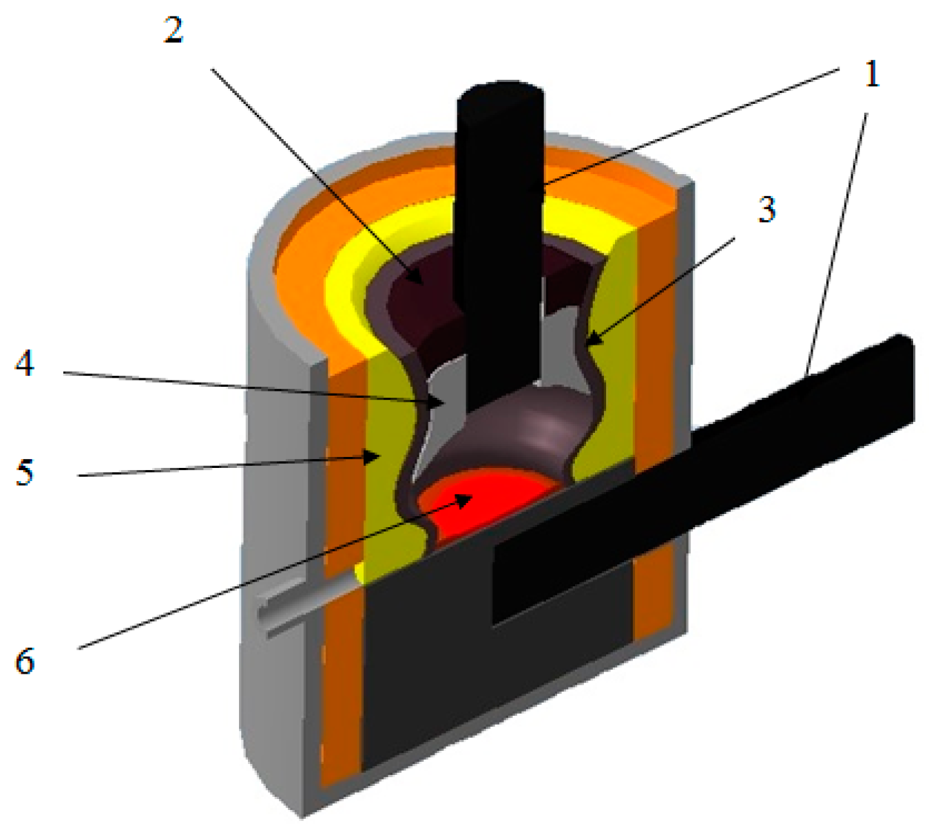
The melting tests of the technical-grade silicon using briquettes were conducted in a large laboratory single-phase arc furnace with a graphite electrode and a conductive hearth with a power of 200 kVA (Figure 1).
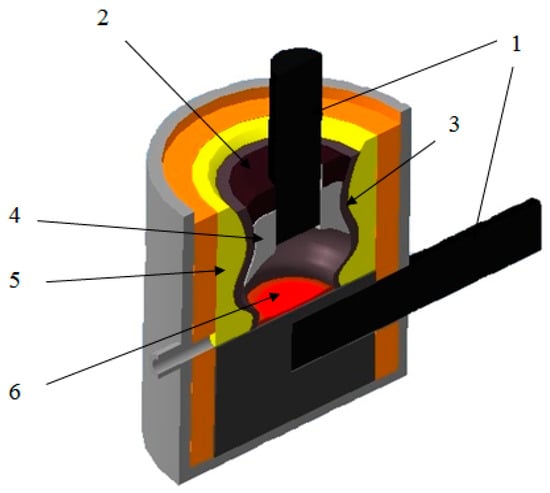
Figure 1.
Structure of bath in the 200 kVA ore-thermal furnace. 1—electrodes; 2—initial charge; 3—zone of softened charge; 4—transition zone; 5—wall accretion; 6—melt and metal carbide coating.
The electric furnace has two electrodes. One electrode is coked in the hearth by the hearth mass, i.e., the electric furnace has a structure similar to the Mige electric furnace. The transformer is powered by a voltage of 380 V [30].
The electric furnace is powered with two OSU-100/0.5 transformers connected in parallel. The arc discharge temperature of 2500–4500 °C is provided via a graphite electrode with a diameter of 150 mm. The furnace is lined with fireclay bricks. The furnace bath is formed as an ellipse with axes of 55–65 cm, elongated towards the tap hole. The distance from an electrode to a tap hole block is 21–22 cm, and to the back wall of the furnace is 29–30 cm. The bath depth is 35–40 cm. The hearth to a level of the furnace tap hole is sintered from an electrode mass which has been coked for 12 h under current with periodic shutdowns of the furnace. An electrode is moved mechanically by hand. The furnace is equipped with an electric meter connected via a 400/5 current transformer (with a factor of 80). Devices for measuring primary current and secondary voltage are also available. The limits of current variation on the high side are 0–500 A, and voltage on the low side is 0–50 V.
The crystalline silicon was discharged through a tap hole. The tap hole was closed and opened with a wooden pole. The secondary voltage can be varied in steps. The furnace transformer has four voltage steps: 18.4 V; 24.5 V; 36.8 V; and 49.0 V. The voltage drop during furnace operation is approximately 4–8 V depending on the voltage step. A larger voltage drop is recorded at high steps.
The main electrical characteristics and technical parameters of the 200 kVA ore-thermal electric furnace are listed in Table 2 and Table 3.
Table 2.
The rated electrical characteristics of transformer OSU − 100/0.5 × 2 with a total capacity of 200 kVA.
Table 3.
The main technical parameters of the electric furnace equipped with a 200 kVA transformer.
Before testing, work was conducted to prepare the ore-thermal furnace for the electric melting. The electric furnace was heated for 24 h on a coke bed used as a conductor of the electric current and to preserve the hearth. At the end of the heating period, the electric furnace was completely cleaned of coke bed residues. The electrical mode of the heating period was under 24.6 V of secondary voltage and a 150–200 A high-side current.
The hearth and assembly of the tap hole were sintered with the crushed electrode mass. A nominal secondary voltage of 36 V along with a sag voltage of 32 V and a current of 2500 A were maintained during the smelting process. The first two charges of the charge were loaded with a deficiency of reducing agent for the formation of crust.
To ensure uniform build-up of the furnace top, the charge was loaded manually around the electrodes in small portions as it settled. The metal from each discharge was weighed, after which a sample was taken for chemical analysis.
The melting of technical silicon began on a classic lump charge mixture of a homogeneous fraction (within 20–50 mm), consisting of quartz, wood chips, and a mixture of reducing agents in the form of coke, coal, and charcoal. Conventionally, the entire process of large-scale laboratory tests can be divided into 4 periods, where the 1st period was melting on a standard charge, and the next three periods involved are 30, 50, and 100% replacement with briquettes.
During all periods of furnace operation, there was no accumulation or release of slag. In the process of obtaining the output the tap hole always gasped. This indicated the formation of a working gas cavity with at a high temperature (full flow of chemical reactions) and the absence of excessive slag which would have hindered the output of metal.
Practically for the entire test period of 11 days, the operation of the 200 kVA ore-thermal furnace was characterized by the deep fitting of an electrode (at the level of the hearth) and the stable electrical mode. The stable electrical mode and the deep electrode fitting allowed us to switch to the highest transformer stage—49 V (stage No. 4)—and to operate on it for 6 days. The electrical modes of the melting process at different charge composition variants are given in Table 4.
Table 4.
The electrical modes of the melting process at different variants of charge composition.
The work on smelting technical silicon in the first period on standard charge was carried out at 2 voltage stages. This approach allowed for an increase in the voltage indicators, due to which the capacity of the furnace transformer increased accordingly. Also, with this method of supplying the load, losses during power transmission are reduced, the load on the current leads is reduced. Operating on a high top allowed the working crucible of the furnace top to be significantly enlarged. This approach helped to stabilize and increase the current load (part of the current went through the furnace top). For instance, when the operation was on a low furnace top and constant fitting of the furnace top occurred, the crucible was narrowed to a size of 30–35 cm (maximum).
During the operation on a high furnace top, the dimensions of the crucible reached 50–55 cm in diameter by the end of the campaign. The partial erosion, corrosion, and recovery of the fireclay lining were found. The partial erosion and corrosion of the second outer layer of fireclay brick near the furnace shell were observed. Such erosion of fireclay lining during the melting of technical-grade silicon and complex ferroalloys has not been previously recorded by us and can be explained as follows:
- -
- The stable and continuous operation in the 4th stage;
- -
- Operation on the high furnace top—heat accumulation;
- -
- Aggressive impact on the lining of alkali metal oxides (Na2O and K2O) contained in liquid glass;
- -
- Long-term stable operation of the furnace with an excess of reducing agent.
The main disadvantage of the high furnace top was its sintering and the problems during the fitting. During the operation on the standard charge and the charge with a 30% replacement to briquettes, problems did not appear. The sintered furnace top had a small thickness and was easily knocked down. During the transition to 50 and 100% replacement, the thickness of the furnace top increased to 20–30 cm, i.e., the furnace top rose from the inside. This made it difficult to knock down the furnace top, which resulted in the necessity of recovering segments of the furnace top in the form of sinters.
3. Theoretical Mechanism of the Silicon Reduction Process
The process of silicon reduction in an electric furnace is continuous. As the charge melts, more of the charge is loaded into the furnace, and silicon is released from the furnace through a tap hole. The composition of the charge is calculated for 100 kg of quartzite or quartz with an excess of reducing agent of 10–15% above the theoretically required amount according to Equation (1) [13]:
SiO2 + 2C → Si + 2 CO
The carbothermic reduction of silicon from silica is implemented in several stages and is accompanied by the formation and consumption of intermediate interaction products—gaseous silicon monoxide (SiO) and solid crystalline silicon carbide (SiC). Silicon carbide is formed as a result of the interaction of SiO with a solid carbonaceous reducing agent at the phase boundary “reducer—gas phase”. It is known that the interaction of silica with carbon can occur only through the formation of a reactive gas phase that ensures contact between the solid oxide and the reducer.
To describe the mechanism of silicon reduction during its melting in submerged arc furnaces, the HSC Chemistry 9 software package was used in this study. Based on HSC Chemistry 9, a thermodynamic diagram analysis of the melting process of metallurgical silicon was conducted based on the Si–O–C system. Elements such as Al, Ca (in the form of oxides from the charge Al2O3 and CaO), and Fe also participate in the melting process. However, their content is quite low, so they were not considered in these thermodynamic calculations.
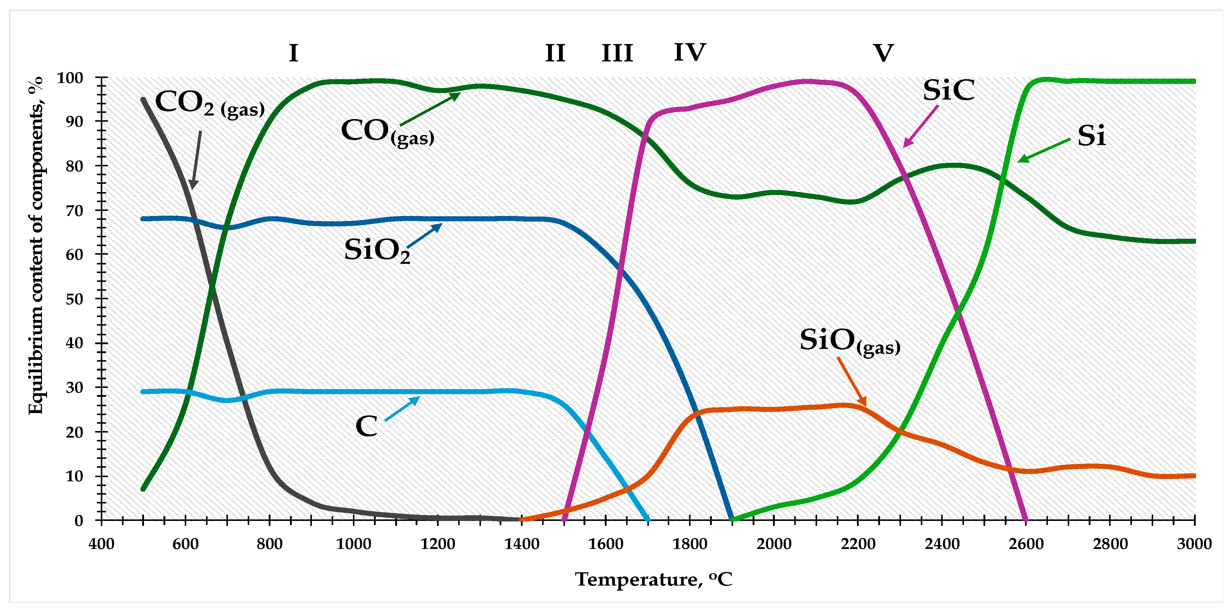
The results of the thermodynamic diagram analysis can be presented as the temperature dependence of the equilibrium composition of the Si–O–C system in the range of 500–3000 °C, as shown in Figure 2.
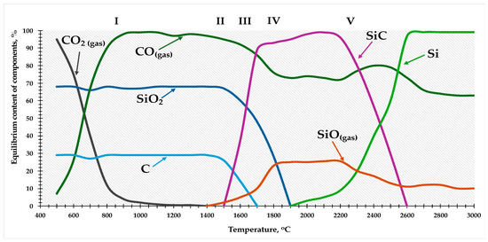
Figure 2.
Temperature dependence of the equilibrium composition of the Si–O–C system in the range of 500–3000 °C.
The results of the thermodynamic analysis showed that the carbothermic reduction of silicon can be implemented in several stages and is accompanied by the formation and consumption of intermediate interaction products—gaseous silicon monoxide (SiO) and solid crystalline silicon carbide (SiC).
According to Figure 2, theoretically, the process of silicon reduction can be divided into 5 stages, which can be represented in the form of the following reactions (2)–(7):
I—C + CO2 → 2CO, below 1400 °C;
II—SiO2 + C → SiO + CO, 1400–1550 °C;
SiO + 2C → SiC + CO;
III—SiO2 + 3C → SiC + 2CO, 1550–1700 °C;
IV—2SiO2 + SiC → 3SiC + CO, 1700–1900 °C;
V—SiO + SiC → 2Si + CO, 1900–2600 °C.
In the studied system, the main components of the gas phase are silicon and carbon monoxide, while the condensed phases are SiO2, SiC, C, and Si. All these phases are practically mutually insoluble. The real composition of the gas phase is undoubtedly much more complex, but due to the small amounts (less than the main substances by 1–2 orders of magnitude), such components as Si2O2, Si, SiC2, Si2C, and others are not taken into account and, for this reason, they are not included in the calculation procedures.
The primary condensed product of the interaction of silicon dioxide with carbon is silicon carbide, which is formed at the phase boundary “carbon reducer—gas phase”. And the formation of SiC is an integral stage of the overall reduction process. According to [31,32,33,34], the interaction of silica with carbon can occur only through the stage of forming a reactive gas phase, which ensures mass transfer between the oxide and the reducer, and the most significant influence on the reaction rate is exerted by the surface area of the reducer. Silicon carbide forms on the surface of the carbonaceous reducer. The properties of the carbide phase are largely determined by the state of the carbonaceous reducer, its nature, and the conditions for the reduction process.
By analyzing the curves of the main component contents in Figure 2, it is possible to trace the dynamics of the formation and consumption of intermediate components in the silicon reduction process. As noted above, the crucial role in the complex multistage mechanism of silicon reduction belongs to gaseous silicon monoxide and solid silicon carbide, with SiO in this scheme functioning as a reactive gas, ensuring diffusional mass transfer between the silica and the reducer.
As the charge materials are heated and move deeper into the bath, conditions are created for reduction processes to occur. As shown in Figure 2, at 1550 °C, there is a decrease in the concentration of silica and solid carbon, indicating the possible occurrence of reaction (5) with the formation of silicon carbide and SiO. This reaction is a summary, including the occurrence of two consecutive processes via reactions (3) and (4), evidenced by the noticeable increase in silicon carbide concentration above 1550 °C.
As mentioned earlier, the reaction of silicon monoxide formation via reaction (3) precedes its consumption via reaction (4), which is one of the reasons for high silicon losses in the form of SiO gas and products of its disproportionation and condensation with outgoing furnace gases.
The disappearance of free carbon at 1700 °C contributes to the enrichment of the gas phase with gaseous silicon monoxide, formed in the range of 1700–1900 °C via reaction (6). This phenomenon has a positive value as it is a necessary condition for the formation of elemental silicon via reaction (7). The figure shows that its occurrence becomes possible at a temperature above 1900 °C. Further temperature increases sharply intensify the reaction of silicon carbide and silicon monoxide consumption. As a result, the concentration of elemental silicon in the condensed phase reaches 100% at 2600 °C. However, silicon carbide completely disappears, and the SiO content in the gas phase falls to 9.5%.
The data provided indicate that a crucial condition for the complete reduction of silicon is a high reaction space temperature. The zone of the highest temperature and active silica reduction, where conditions for reaction (7) are met, is limited to the sphere in the lower part of the submerged arc furnace. The average temperature in the sphere is 2680 °C, with temperature fluctuations from 2000 to 3000 °C according to some data, up to 3500 °C). Outside this region, the main reduction reaction will even be hindered at a favorable reagent ratio, i.e., reaction (7) does not develop at lower temperatures (up to 1900 °C), and silicon monoxide cannot participate in the formation of elemental silicon. This situation is exacerbated by the instability of the size and location of the high-temperature zone in the furnace, due to the uneven loading of the charge. As a result, a significant part of the SiO gas is carried out of the reaction space and irretrievably lost.
It can be assumed that due to the presence of an organized gas flow in the furnace, the proportion of SiO in the gas phase will be higher than the values predicted with equilibrium thermodynamics. In these circumstances, the ability of the blast furnace bed to assimilate SiO gas and its disproportionation products as fully as possible becomes especially important, since the losses of raw materials and energy spent on the formation of gaseous silicon monoxide, which does not participate in the processes of elemental silicon formation, are irreversible.
The use of charged materials in the form of briquettes, or briquetted monocharge, can significantly improve these conditions. Briquettes ensure a more uniform distribution of materials in the furnace and help maintain consistently high temperatures. This reduces the probability of silicon loss in the form of gaseous SiO and increases the yield of elemental silicon.
4. Results and Discussion
4.1. Briquetting Results
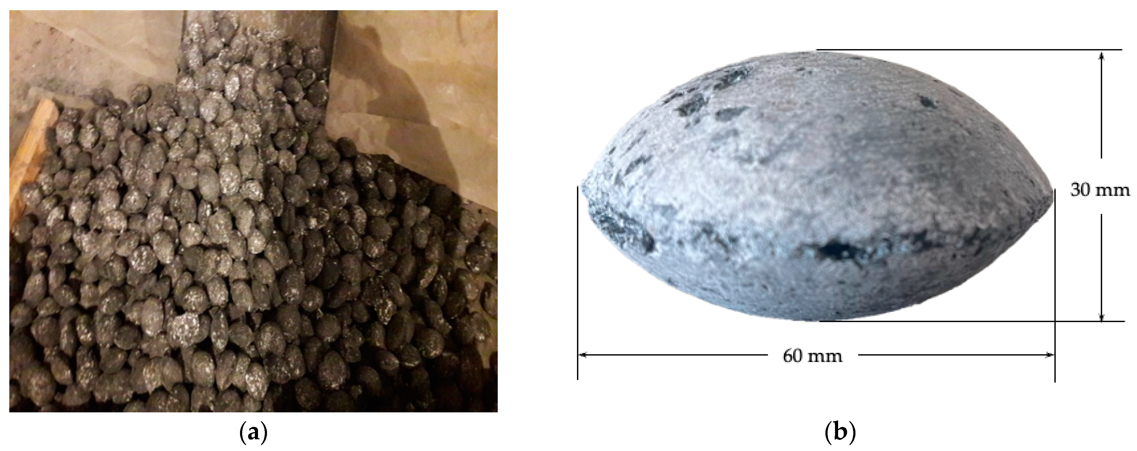
The total weight of the batch of suitable briquettes (Figure 3a) after natural drying was 1–1.2 tons. As a result, high-strength briquettes in the form of a flattened ellipsoid, 60 mm in diameter and 30 mm in height (Figure 3b), were obtained.
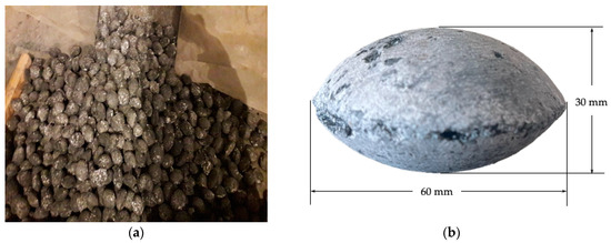
Figure 3.
A batch of briquetted monocharge: (a) general view; (b) briquette.
It is worth noting that after drying, the resulting briquettes were quite strong both visually and during transportation to the place where the furnace was installed.
4.2. Results of Melting
After drying, the briquettes were tested as a raw material for the melting of metallurgical silicon under 30, 50, and 100% of standard charge replacement.
In general, the process of melting metallurgical silicon in a 200 kVA ore-thermal furnace was satisfactory and stable. Stoppages of the furnace due to burning out of inserts and overheating of contacts and current conductors, which are typical for unstable electrical operation of the furnace, were not found. The metal was released every two hours as it melted through the tap hole without any problems.
The main technological parameters for the melting of the technical-grade silicon during this study at different variants of charge composition are shown in Table 5.
Table 5.
Technological parameters of the melting process.
To ensure the optimal flow of reduction processes in the furnace, the bulk density of the charge must be sufficient for uniform melting and obtainment of the required reaction rate. Under experimental conditions, for each calculation of the charge composition, the bulk density was approximately 0.60 t/m3, which also ensured the optimal gas permeability index.
It was found that it is necessary to reduce the solid carbon (Csolid) excess ratio in a charge from 1.3 to 1.4 (on a standard charge in the 200 kVA ore-thermal furnace at a heating stage) to 1.15 to 1.2 when using briquetted monocharge materials. It was connected with the following:
- -
- Less solid carbon burn-up in briquettes where the carbonaceous reducing agent was isolated from exposure to air oxygen;
- -
- Partial mechanical removal of microsilica from the surface of briquettes via hot flue gases;
- -
- The need to take into account the content of solid carbon (3–4%) in the composition of microsilica.
It is also worth noting here that by maintaining these process parameters, as well as the specific compositions of the charge mixtures, it was possible to increase the furnace productivity from 1.72 kg (with a standard charge) to 2.0 kg (with a 30% share of briquettes in the charge) of technical silicon per hour. This indicates that there was a reduction in silicon losses in the form of gaseous SiO.
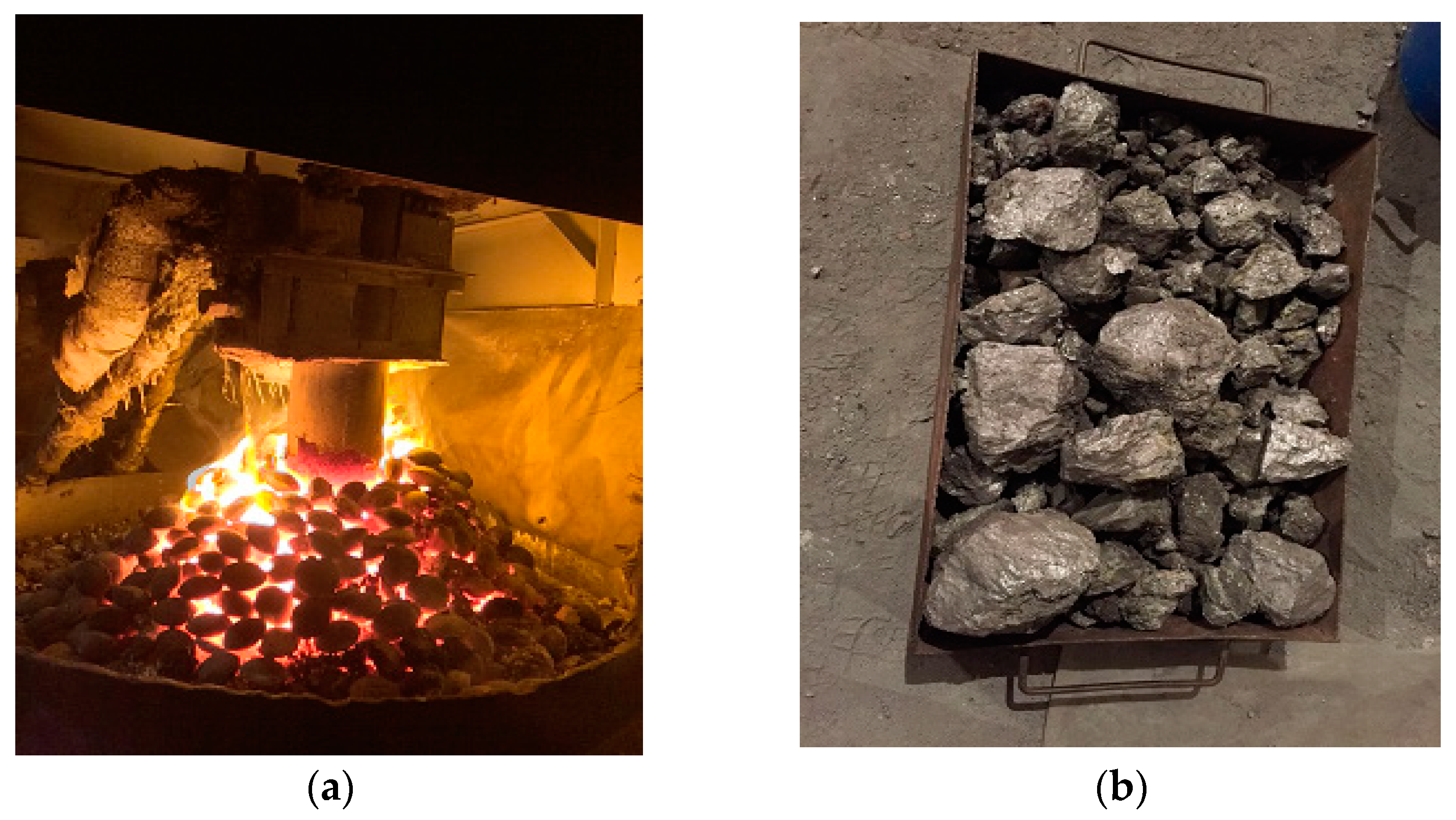
Figure 4 shows a general view of briquettes melting in a furnace and finished metallurgical silicon ingots after cooling.
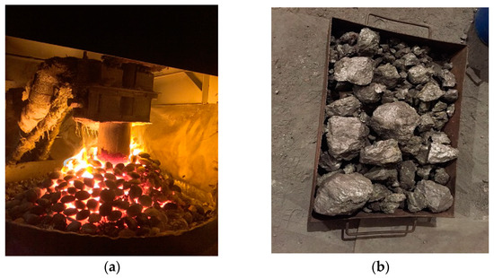
Figure 4.
Melting process: (a) briquetted monocharge melting in furnace; (b) ingots of the metallurgical silicon.
The material balance and data on the average chemical composition of silicon, which were obtained as a result of testing, are presented in Table 6 and Table 7.
Table 6.
Material balance of melting process.
Table 7.
Average chemical composition of silicon obtained as a result of tests.
According to the test results, it is obvious that with the transition to briquetted monocharge, the technological process of melting technical silicon improves. This is especially obvious with a 30% replacement.
It is possible to observe an increase in the silicon extraction rate with 30 and 50% replacement with briquettes from 70.95% on a standard batch to 82.76 and 78.18% when using briquettes. During the transition to briquetted monocharge, the aluminum content decreased from 1.9–2.1% to 0.5–0.7%, calcium decreased from 0.2–0.3% to 0.07–0.1%, and titanium decreased from 0.2–0.23% to 0.11–0.13%. Phosphorus content increased from 0.004–0.005 to 0.011–0.013%.
However, the main difficulties arise with the complete (100%) replacement of the charge with briquettes. Here, a slight deterioration in the technological process was observed. In particular, the instability of the electric mode of the furnace, low metal yield, and a decrease in silicon extraction were noted. The main problem was the change in heat transfer and the composition of the charge, which leads to instability of the electric mode of the furnace and a decrease in the silicon yield. This is primarily due to the low thermal conductivity of microsilica and changes in the reactivity of the materials, which require additional energy to maintain the desired temperature and process stability. To prevent these difficulties, it is important to carefully control the briquette loading process and maintain a stable temperature regime, especially in the zone of active silicon reduction.
A slight increase in the dust content of the flue gases was observed during the melting process of the technical-grade silicon when only the briquetted monocharge was used. Based on the experience of conducting technological processes of melting using briquettes, insignificant dust emission was also observed, for instance, the melting of high-carbon ferrochrome using briquetted dust from a gas purification system and in the melting of ferrosilicon manganese using a monocharge of fine manganese ore and coke [35]. This is because briquettes consist of dust-like raw materials. To work with this material and achieve high performance of the process, it is necessary to adhere to some specifics of ore-thermal furnace operation.
Thus, the results of the conducted preliminary studies prove the possibility of using briquetted monocharge for smelting silicon of metallurgical grades. Successful results were obtained with 30–50% replacement of standard charge with briquettes. The obtained results are the basis for further studies on the development of the technology of full-fledged use of briquetted monocharge as a raw material for smelting silicon.
5. Economic Efficiency of the Monocharged Using
Based on this study, it was also possible to make a tentative conclusion about the economic efficiency of the monocharge used. Approximate calculations of the charge mixture using standard traditional technology and the developed technology using briquetted monocharge are given in Table 8.
Table 8.
Comparative cost of charge materials for melting of metallurgical silicon using traditional and developed technology.
Based on calculations, the positive economic effect can amount to from USD 300 to 400 per ton of technical silicon, which, with a production volume of 20 thousand tons, will provide additional income of USD 2–2.5 million.
The economic effect was calculated without energy costs, since with the recommended 30% replacement share, the energy consumption was 42.38 kWh/kg, which, within the limits of error, coincides with the electricity consumption for a standard charge of 41.96 kWh/kg (Table 4) and the average for the entire company is 42.41 kWh/kg.
The calculations clearly demonstrate what economic effect can be achieved only by partly replacing charge materials and with a partial transition to monocharge.
6. Conclusions
The following conclusions can be drawn from the results of the conducted tests:
- The process of briquetting microsilica together with a carbonaceous reducing agent (semicoke) in a ratio of 65/35 was developed and tested. As a result, a pilot batch of high-strength briquettes (monocharge) was produced;
- Under large-scale laboratory conditions on a 200 kVA ore-thermal furnace, the technological process of melting technical silicon with 30, 50, and 100% replacement of the traditional charge mixture with microsilica briquettes was developed;
- The results of these studies showed that under the conducted conditions, the optimal results were obtained with 30% replacement of the standard charge with briquettes. This replacement allowed for the obtainment of an alloy with an average silicon content of 96.38%. The silicon extraction rate into the alloy was 82.76%. The productivity of the process was 2.00 kg of technical silicon per hour. Moreover, with the standard charge mixture, the furnace productivity was 1.72 kg of alloy per hour. Obviously, with 30%, an intensification of the reduction processes and the melting process as a whole was recorded compared to the standard charge (without briquettes);
- The economic efficiency of the partial use of briquettes made of microsilica and carbonaceous reducing agent was established;
- Therefore, based on the experience shown in this study, for the implementation of the developed technology in real silicon production with high-power furnaces, it is recommended to use a share of briquettes of no more than 10–15%. The increase in the proportion of briquettes must be carried out with the gradual development of the process and the establishment of the technological mode of operation of the furnace.
Therefore, the production of briquettes in the existing production of metallurgical silicon will harmoniously fit into the technological line. The dust emissions resulting from the use of briquettes will not be significant.
Thus, several topical problems will be solved:
- The ecological problem of utilization of production waste microsilica;
- The raw material problem for quartz and its quality;
- The intensification of the melting process due to closer contact of the carbonaceous reducing agent and silicon oxide;
- The possibility to purchase cheaper carbonaceous reducing agents with smaller size (charcoal, special coke, etc.);
- The possibility of wider involvement in silicon production of such limitedly used carbonaceous reducing agents as screenings of charcoal and petroleum coke.
Author Contributions
Conceptualization, A.B. and Y.S.; Methodology, A.B., Y.S., A.M. (Azat Mussin), S.S., and A.M. (Amir Makishev); Investigation, A.B., Y.S., A.M. (Azat Mussin), S.S., and A.M. (Amir Makishev); Writing—original draft, N.V.; Writing—review and editing, N.V.; Visualization, A.M. (Azat Mussin), S.S., and A.M. (Amir Makishev); Supervision, A.B. and Y.S. All authors have read and agreed to the published version of the manuscript.
Funding
This research has been funded by the Science Committee of the Ministry of Science and Higher Education of the Republic of Kazakhstan (Grant No. AP14870218).
Data Availability Statement
The original contributions presented in this study are included in this article, further inquiries can be directed to the corresponding author.
Conflicts of Interest
The authors declare no conflicts of interest.
References
- U.S. Geological Survey. Mineral Commodity Summaries 2024; U.S. Geological Survey: Reston, VA, USA, 2024; 212p. [CrossRef]
- Doe, J.; Smith, J.; Johnson, M. Global Silicon Metal Market Report; Ken Research: Gurugram, India, 2024; 106p. [Google Scholar]
- Tan, N.; Han, S.; Wei, K.; Wang, Q. Determination of Silicon Content in Metallurgical-Grade Silicon Refined Slag using Two-Step Dissolution Chemical Analysis Method. Silicon 2024, 16, 123–132. [Google Scholar] [CrossRef]
- Wen, J.; Zhang, H.; Chen, Z.; Li, X. Exergy Analysis of Silicon Metallurgy in 22.5 MVA Submerged Arc Furnaces. Silicon 2023, 15, 1897–1912. [Google Scholar] [CrossRef]
- Yuan, S.; Lu, H.; Wang, P. Study on Producing Solar Grade Silicon by Carbothermal Reduction of Andalusite Ore. In Energy Technology 2017; The Minerals, Metals & Materials Series; Zhang, L., Ed.; Springer: Cham, Switzerland, 2017; pp. 345–357. [Google Scholar] [CrossRef]
- Serikkanov, A.; Pavlov, A.; Mukashev, B.; Turmagambetov, T.; Kantarbayeva, D.; Zholdybayev, K. The Possibility of Silicon Purification by Metallurgical Methods: Part I. Processes 2022, 10, 1353. [Google Scholar] [CrossRef]
- Leonova, M.S.; Timofeeva, S.S. Study on the Processing of Gas Purification Dust from Silicon Production into Nanoadditives for Cast Irons. IOP Conf. Ser. Earth Environ. Sci. 2019, 229, 012022. [Google Scholar] [CrossRef]
- Aasly, K.; Dosaj, V. Assessment of Production Performance of Quartz in the Si-Furnace. In Proceedings of the Silicon for the Chemical and Solar Industry XIII, Kristiansand, Norway, 13–16 June 2016. [Google Scholar]
- Halvorsen, G.; Schüssler, G. Sustainable Silicon Production. In Organosilicon Chemistry Set; Auner, N., Weis, J., Eds.; Wiley-VCH: Weinheim, Germany, 2005; pp. 495–508. [Google Scholar] [CrossRef]
- Østensen, O.J. Upgrading Off-Grades from the Silicon Process: Increasing the Silicon Yield from Elkem Thamshavn Using Mechanical or Metallurgical Separation. Master’s Thesis, Norwegian University of Science and Technology, Trondheim, Norway, 2011. Available online: https://ntnuopen.ntnu.no/ntnu-xmlui/handle/11250/247760 (accessed on 2 August 2024).
- Legemza, J.; Findorák, R.; Buľko, B.; Briančin, J. New Approach in Research of Quartzes and Quartzites for Ferroalloys and Silicon Production. Metals 2021, 11, 670. [Google Scholar] [CrossRef]
- Jarkin, V.; Kisarin, O.; Kritskaya, T. Methods of Trichlorosilane Synthesis for Polycrystalline Silicon Production. Part 1: Direct Synthesis. Mod. Electron. Mater. 2021, 7, 1–10. [Google Scholar] [CrossRef]
- Gasik, M.; Dashevskii, V.; Bizhanov, A. Metallurgy of Silicon and Silicon Carbide. In Ferroalloys Theory and Practice; Springer: Berlin/Heidelberg, Germany, 2020; pp. 35–55. [Google Scholar] [CrossRef]
- Sariyev, O.; Kelamanov, B.; Dossekenov, M.; Davletova, A.; Kuatbay, Y.; Zhuniskaliyev, T.; Abdirashit, A.; Gasik, M. Environmental Characterization of Ferrochromium Production Waste (Refined Slag) and Its Carbonization Product. Heliyon 2024, 10, e30789. [Google Scholar] [CrossRef]
- Karlina, A.I. Technology of Processing of Dust from Gas Purification System of Silicon Production in Modifying Nanoaditives for Cast Irons. Candidate of Technical Science. Ph.D. Thesis, Institute of Metallurgy, Ural Branch of the Russian Academy of Sciences, Ekaterinburg, Russia, 2019; p. 134. (In Russian). [Google Scholar]
- Nemchinova, N.; Mineev, G.; Tyutrin, A.; Yakovleva, A. Utilization of Dust from Silicon Production. Steel Transl. 2017, 47, 763–767. [Google Scholar] [CrossRef]
- Galevsky, G.; Rudneva, V.; Galevsky, S. Microsilica in the Production of Silicon Carbide: The Results of Testing and Evaluation of Technological Challenges. In Proceedings of the IOP Conference Series: Materials Science and Engineering, Ekaterinburg, Russia, 20 October 2018. [Google Scholar]
- Chandrasekhar, S.; Pramada, P.N.; Raghavan, P.; Satyanarayana, K.G.; Gupta, T.N. Microsilica from Rice Husk as a Possible Substitute for Condensed Silica Fume for High Performance Concrete. J. Mater. Sci. 2002, 21, 1245–1247. [Google Scholar] [CrossRef]
- Friede, B. Microsilica—Characterization of an Unique Additive. In Proceedings of the International Inorganic-Bonded Fiber Composites Conference (IIBCC), Sao Paulo, Brazil, 15–18 November 2006; Volume 10. [Google Scholar]
- Panjehpour, M.; Abdullah, A.; Ali, A.; Demirboga, R. A Review for Characterization of Silica Fume and Its Effects on Concrete Properties. Int. J. Sustain. Constr. Eng. Technol. 2011, 2, 1–7. [Google Scholar]
- Ahmad, S.; Al-Amoudi, O.; Khan, S.; Maslehuddin, M. Effect of Silica Fume Inclusion on the Strength, Shrinkage and Durability Characteristics of Natural Pozzolan-Based Cement Concrete. Case Stud. Constr. Mater. 2022, 17, e01255. [Google Scholar] [CrossRef]
- Mermerdaş, K.; İpek, S.; Algın, Z.; Ekmen, Ş.; Güneş, İ. Combined Effects of Microsilica, Steel Fibre and Artificial Lightweight Aggregate on the Shrinkage and Mechanical Performance of High Strength Cementitious Composite. Constr. Build. Mater. 2020, 262, 120048. [Google Scholar] [CrossRef]
- Baisanov, S.; Lu, N.; Zhinova, Y.; Narikbaeva, G. Thermodynamic Analysis of Phase Diagrams Based on the Concept of the Bjerrum–Guggenheim Osmotic Coefficient. Acta Metall. Slovaca 2024, 30, 77–89. [Google Scholar] [CrossRef]
- Ringdalen, E.; Tangstad, M. Softening and Melting of SiO2, an Important Parameter for Reactions with Quartz in Si Production. In Advances in Molten Slags, Fluxes, and Salts: Proceedings of the 10th International Conference on Molten Slags, Fluxes and Salts; Reddy, R.G., Chaubal, P., Pistorius, P.C., Pal, U., Eds.; Springer: Cham, Switzerland, 2016; pp. 345–357. [Google Scholar] [CrossRef]
- Belskii, S.A.; Nemchinova, N.V. Thermodynamic Model of Silicon Smelting in Ore-Smelting Furnaces. Mater. Sci. Forum 2020, 989, 504–510. [Google Scholar] [CrossRef]
- Varyushenkov, A.M.; Okladnikov, V.P.; Issayeva, Y.P.; Saltykov, A.M.; Khrennikova, L.P. Briquetted Mixture to Produce the Technical-Grade Silicon and Method of Its Preparation. RF Patent 2036144, 27 May 1995. [Google Scholar]
- Kurbanov, M.S.; Abdurakhmanov, B.M.; Ashurov, K.B.; Kim, Y.P. Return of Fine Wastes of Production of Technical-Grade Silicon and Ferrosilicon into the Technological Process. In Proceedings of the XI Conference on Actual Problems of Physics, Materials Science, Technology and Diagnostics of Silicon, Novosibirsk, Russia, 12–15 September 2016; p. 87. (In Russian). [Google Scholar]
- Nemchinova, N.V.; Leonova, M.S.; Tyutrin, A.A. Experimental Works on the Melting of Pelletized Charge in Silicon Production. Bull. Irkutsk State Tech. Univ. 2017, 21, 209–217. [Google Scholar] [CrossRef]
- Isin, D.K.; Baisanov, S.O.; Mekhtiev, A.D.; Baisanov, A.S.; Isin, B.D. Technology for Producing Crystalline Silicon with the Use of Non-Traditional Reducing Agents. Metallurgist 2014, 57, 1022–1029. [Google Scholar] [CrossRef]
- Vorobkalo, N.; Baisanov, A.; Makhambetov, Y.; Mynzhasar, Y.; Nurgali, N. Technological Research of Process for Producing Titanium Rich Slag and Complex Titanium-Containing Ferroalloy. Heliyon 2023, 9, e18989. [Google Scholar] [CrossRef]
- Nemchinova, N.V.; Leonova, M.S.; Timofeev, A.K. Study of the process of obtaining metallurgical silicon using pelletized charge by the method of thermodynamic modeling. iPolytech J. 2016, 7, 162–171. (In Russian) [Google Scholar] [CrossRef]
- Jacobson, N.; Opila, E. Thermodynamics of Si-CO System. Metall. Trans. A 1993, 24, 1212–1214. [Google Scholar] [CrossRef]
- Haase, V. The Phase Diagram Si-C-O. In Si Silicon (Part of the Book Series: Gmelin Handbook of Inorganic and Organometallic Chemistry—8th Edition); Katscher, H., Sangster, R., Schröder, F., Eds.; Springer: Berlin/Heidelberg, Germany, 1985; pp. 522–526. [Google Scholar] [CrossRef]
- Danes, F.; Saint-Aman, E.; Coudurier, L. The Si-C-O system. J. Mater. Sci. 1993, 28, 489–495. [Google Scholar] [CrossRef]
- Zhunussov, A.K.; Tolymbekova, L.B.; Bykov, P.O.; Zayakin, O.V. Melting Ferrochrome Using Chrome-Ore Briquettes. Metallurgist 2024, 67, 606–613. [Google Scholar] [CrossRef]
Disclaimer/Publisher’s Note: The statements, opinions and data contained in all publications are solely those of the individual author(s) and contributor(s) and not of MDPI and/or the editor(s). MDPI and/or the editor(s) disclaim responsibility for any injury to people or property resulting from any ideas, methods, instructions or products referred to in the content. |
© 2024 by the authors. Licensee MDPI, Basel, Switzerland. This article is an open access article distributed under the terms and conditions of the Creative Commons Attribution (CC BY) license (https://creativecommons.org/licenses/by/4.0/).