Article

Plasma Gasification of a Simulated Low-Level Radioactive Waste: Co, Cs, Sr, and Ce Retention Efficiency

by
Juan Ariel Pullao
1,2,3,
Franco Emmanuel Benedetto
1,2,*,
Gian Franco Binetti Basterrechea
4,
Leonardo Andrés Neira Poblete
1,
Diana Carolina Lago
1,5 and
Miguel Oscar Prado
6
1
Departamento Materiales Nucleares, Comisión Nacional de Energía Atómica, Av. Exequiel Bustillo 9500, San Carlos de Bariloche 8400, Río Negro, Argentina
2
Facultad de Ciencias Exactas y Naturales (FCEN), Universidad Nacional de Cuyo (UNCuyo), Padre Jorge Contreras, M5502 JMA, Mendoza 1300, Argentina
3
Escuela de Producción, Tecnología y Medio Ambiente, Universidad Nacional de Río Negro (UNRN), Anasagasti 1463, San Carlos de Bariloche 8400, Río Negro, Argentina
4
Facultad Regional de Buenos Aires (FRBS), Universidad Tecnológica Nacional (UTN), Mozart 2300, Ciudad Autónoma de Buenos Aires C1407, Argentina
5
FunGlass—Centre for Functional and Surface Functionalized Glass, Alexander Dubček University of Trenčín, 911 50 Trenčín, Slovakia
6
Consejo Nacional de Investigaciones Científicas y Técnicas (CONICET), Av. de los Pioneros 2350, San Carlos de Bariloche 8400, Río Negro, Argentina
*
Author to whom correspondence should be addressed.
Processes 2024, 12(9), 1919; https://doi.org/10.3390/pr12091919
Submission received: 22 July 2024 / Revised: 21 August 2024 / Accepted: 5 September 2024 / Published: 6 September 2024
(This article belongs to the Special Issue Advances in Wastewater and Solid Waste Treatment Processes)

Abstract

:
Thermal plasma is a versatile technology that can be used to treat various types of wastes, including vegetal and mineral oils, solvents, plastics, paper and cardboard, glasses, bricks and rocks, metals, clothes, and mixtures of these materials. In this study, we utilized a commercial plasma cutter as a thermal plasma source to decrease the volume of a simulated low-level radioactive mixed solid waste. The simulated waste included papers, plastics, clothes, gloves, metals, and stable Co, Cs, Sr, and Ce additives as surrogates of 60Co, 137Cs, 90Sr, and 144Ce, respectively, the latter being typical contaminants in nuclear LLW. As a result of the process, two products were obtained: a solid phase, on which we focused this work, and a gaseous phase. To retain as many as surrogates as possible in the solid final phase, crushed glass from broken bottles was included as a vitrification additive to the original waste. After undergoing heat treatment, a dense vitreous slag was produced along with ashes. The process resulted in a volume reduction of 70%, indicating the successful gasification of organic excess materials. The surrogate elements were retained in the process and were found in the ashes composition: Co (3.4% w/w), Cs (37.7% w/w), and Ce (0.6% w/w) and in the glass matrix composition of Co, Cs, Sr and Ce: 72.4 ± 14.7, 32 ± 18.2, 125.3 ± 31.6, 80 ± 13.1% w/w, respectively. For the actual experimental conditions, retention efficiencies were estimated for cobalt (Co) at 72.4 ± 14.7%, cerium (Ce) at 80 ± 13.1%, strontium (Sr) at 125.3 ± 31.6%, and notably cesium (Cs) at 32 ± 18.2%.

1. Introduction

Current governments are seeking to generate electricity using methods that are free from the use of fossil fuels and have low rates of greenhouse gas emissions. Nuclear fission is a proven alternative with potential growth in coming years [1,2]. China alone is planning to build 100 new nuclear power plants (NPPs) by 2030, which illustrates the potential growth of nuclear energy [3].
Radioactive wastes (RWs) are generated as a by-product of the electric power generation process in nuclear reactors, fuel processing plants, hospitals, and research facilities [4]. RW is defined as “radioactive material for which no further use is foreseen, and with characteristics that make it unsuitable for authorized discharge, authorized use or clearance from regulatory control” [5]. States are responsible for the safe management of RW to guarantee and protect the health of living creatures and the environment. The International Atomic Energy Agency (IAEA) determines general guidelines for all stages of RW management [6].
RAWs can exist in solid, liquid, gas, or mixtures and can be classified as very low, low, intermediate, and high-level waste based on their activity concentration [7]. This type of waste must be subjected to treatments that improve its characteristics to protect human health and the environment now and in the future [8]. The goal of the treatment of intermediate and low-level waste is to reduce their volume [9,10,11] and transform them into safer forms for storage, transport, and final disposal, such as incorporating them into glassy and/or cementitious matrices. Low- and intermediate-level wastes (LILWs) contain various radionuclides, including 60Co, 90Sr, 134Cs, and 137Cs [8]. In addition, other radionuclides are present in the wastes generated in fuel manufacture, such as uranium and its isotopes 235U and 238U [12] and those coming from medical applications (mostly with very short half-lives) [13,14].
Thermal processes, such as flame incineration, pyrolysis, and plasma treatment, have been effective in reducing the volume of LILWs and destroying their organic phase [15,16,17,18]. Plasma treatment is considered the most comprehensive method since it can treat all types of wastes [19], resulting in significant volume reduction and destruction of all hazardous components (chemical and biological) inthe wastes [20]. However, during thermal treatment for RW conditioning, some radionuclides may become volatile and escape from the treatment chamber along with the gaseous effluents [21,22,23,24,25]. Therefore, although part of the radionuclides are carried away by gases, maximum retention of the radioactive elements in the solid phase is necessary.
This article explores the vaporization of simulated LLW and the distribution of these radionuclide surrogates within a prototype plasma treatment chamber designed for small-scale mixed waste processing. Additionally, it examines the retention of substitutes in the solid phases, including slag and ash, that are produced. When working with RWs, a compact process is highly desirable as it simplifies operation and enhances safety [26]. To the best of our knowledge, although the problem of volatiles during immobilization has been reported in the literature, scarce quantitative data about Cs retention in the solid phase have been reported until now. In this paper, we present the retention efficiency values of some volatiles, including cesium, in the solid phase.
The transferred arch 4.8 kW plasma torch used in this work is part of commercial plasma cutting equipment that we introduced in a waste treatment reactor along with a custom-designed water refrigerated anode constructed in our department. This novel application of a plasma cutter shows that it is possible to build a small-scale facility with moderate resources for both research purposes and treating small-scale wastes using this technique.
To simulate the radionuclides commonly found in LILWs, their stable elements are used as surrogates. Specifically, for 60Co, 134Cs, 137Cs, and 90Sr, stable Co, Cs, and Sr are used, respectively. For radionuclides such as 144Ce, 141Ce, and others that do not have stable isotopes like 238U and 235U, stable Ce is used. The use of stable elements as surrogates for radionuclides is a common practice in environmental studies. The simulated LLW was prepared from non-radioactive salts; these compounds, however, are recognized as chemically identical to their radioactive counterparts based on the ‘critical’ 60Co, 134Cs, 137Cs, and 90Sr isotopes [27,28,29,30].

2. Materials and Methods

2.1. Experimental Setup

The system used here for thermal plasma treatment of the waste consists of several components, as shown in Figure 1. These include a reactor, a transferred arc plasma torch, a compressed air supply, a copper anode, a cooling water service, and off-gas treatment.
The reaction chamber has a 1.4 L volume and is made of refractory material with a 35 mm wall thickness. The refractory material is composed of 60% Al2O3, 31% SiO2, 3% CaO, 1% Fe2O3, and 5% impurities (w/w). The reactor walls, which contain the reactor chamber, consist of two layers: an internal insulating mineral blanket that is 105 mm thick and made of 50% SiO2 and 50% Al2O3 (w/w) and an external steel structure that is 3 mm thick (Figure 2a). The torch and the anode are located at the bottom of the reaction chamber, and plasma is generated between them (Figure 1). The wastes are fed through the top lid of the reactor and come into contact with the plasma in the lower part of the reaction volume. The organic and inorganic volatile component fractions of the waste are converted to their gaseous states and move out of the reactor through the upper outlet of gaseous effluents (Figure 2a). The inorganic and other non-volatile components of the waste remain inside the reactor until the end of the operation, and they are removed from it once the reactor becomes cold. The operating temperature In the reaction volume, Ich ranges from 1000 to 1400 °C, is monitored by two type S thermocouples (Pt-PtRh) located on the refractory walls.
The experiments were conducted using a commercial Hypertherm plasma cutting torch, which was connected to its Powermax 105 model source (Hipertherm Inc., Hanover, NH, USA). The Powermax 105 has an output voltage of 160 VDC and a variable current range of 30–105 A. For this work, a fixed current of 30 A and a power of 4.8 kW were used in all the experiments. Air was used as plasmatic gas, and the torch was water-cooled to prevent overheating of the internal wires. The compressed air for the torch was supplied using a Kaesser AirCenter SX8 model compressor (Kaesser Compresores, Neuquén, Argentina). The compressor had a working pressure of 8 bar and a flow rate of 8–9 kg/h. The plasma temperatIre, in the absence of fed waste, calculated by an energy balance for these experiments, is about 1900 °C. A copper anode with a diameter of 38 mm and a length of 55 mm was utilized to connect the electric arc from the torch. The anode was positioned directly in front of the torch, separated by a distance of 6–9 mm. To extend its useful life, it was connected to a double stainless steel tube that moved cooling water through its internal wall (Figure 2b). A semi-closed system was used to produce the cooling water, consisting of a cooling tower (number 7 in Figure 1), heat exchanger (number 6 in Figure 1), buffer tank, and circulation pumps. The refrigeration system was manually controlled using valves and flowmeters and monitored by type K thermocouples that sense the temperature of the inlet and outlet water at each refrigeration point. Effluent gas monitoring was conducted at the reactor outlet using a Horiba PG-350 portable gas detector (Horiba Ltd., Kyoto, Japan).

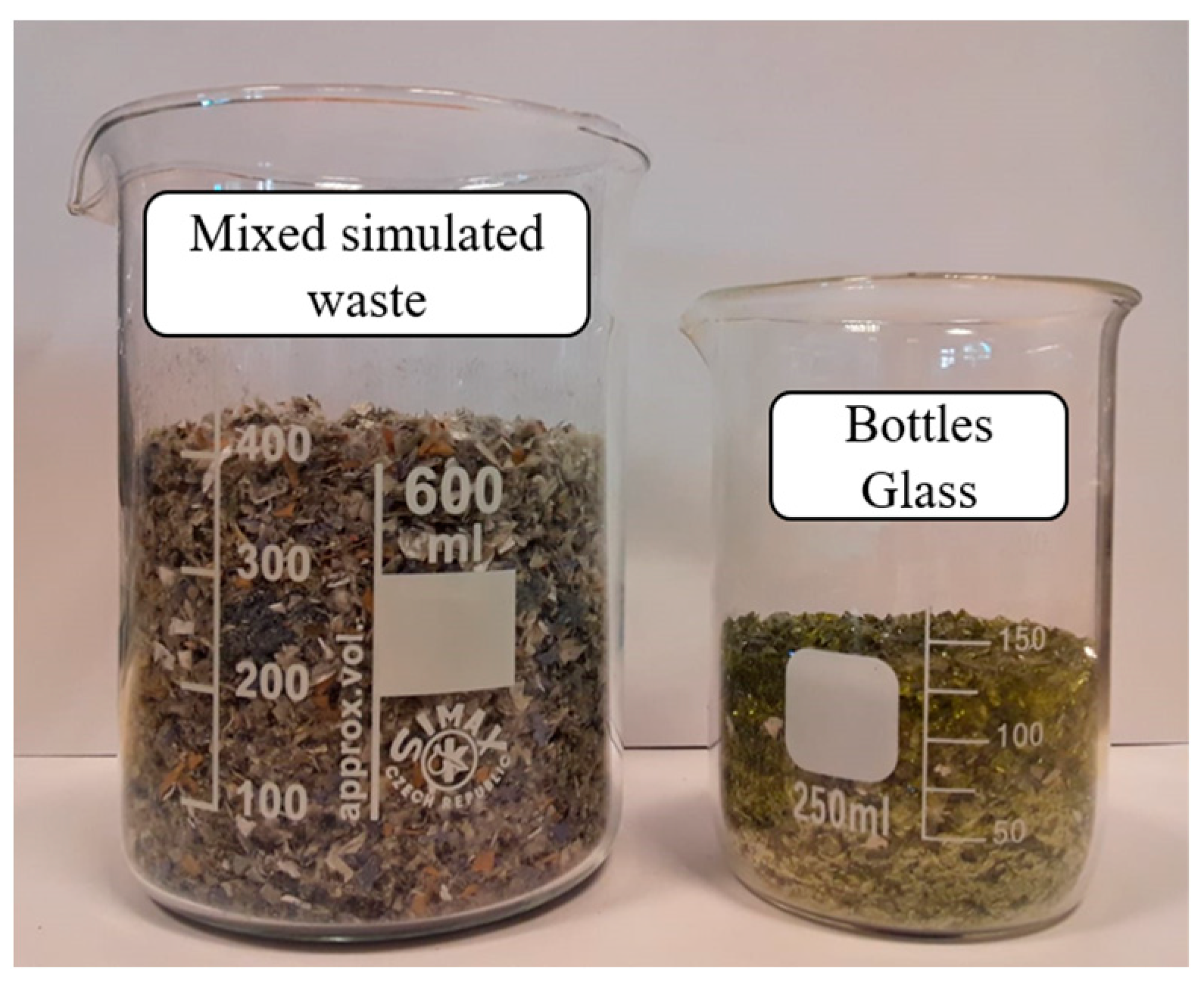
2.2. Sample Preparation

A total of 25 g of simulated non-radioactive waste were prepared for this work. The chemical composition of the SRAWs was taken from Gourvonov et al. [31] (Table 1).
We used the Fritsch brand Pulverisette 25 model (Fritsch GmbH, Berlin, Germany) to shred the materials and mixed them, resulting in a volume of 400 mL (Figure 3). The initial composition was then supplemented with 200 g (125 mL) of crushed commercial glass (bottle glass) (Figure 3). The glass was added as a vitrification additive to capture the waste radionuclides [32].
To simulate the presence of radionuclides 60Co, 137Cs, 134Cs, 90Sr, 144Ce, and 141Ce in the 25 gr of the simulated LLWs, 3 g of Co and 1 g of each stable isotope of Cs, Sr, and Ce were added. The elements were introduced through the compounds Co3O4, CsNO3, Sr(NO3)2, and CeO2 (Sigma-Aldrich, Buenos Aires, Argentina) in the form of solid powders with 99% purity. These quantities were in excess of those found in true LLWs. The surrogate mass oversizing was performed to characterize these materials using instrumental analysis techniques. Finally, the 25 g mixture with 6 g of surrogate compounds was divided into three equal parts and put inside closed paper packets, while the 200 g glass was divided into another 5 equal paper packets. Thus, the 8 packets with a total mass of 231 g and volume of 525 mL were ready for thermal plasma treatment. They were manually fed to the reaction chamber in the following order: first, the 5 glass-containing packets and, afterward, the 3 containing the simulated waste.

2.3. Plasma Reaction Chamber Operation

The experiment began with the plasma torch being turned on and the temperature inside the chamber reaching 600 °C after 60 min. At this point, the first package containing glass was fed into the chamber, which caused a slight perturbation of the gasification chamber temperature and the CO concentration. Once the CO concentration decreased to permissible exposure values, the second glass pack was fed, and this procedure was repeated with the remaining three packages containing glass.
After approximately 120 min, the temperature in the chamber reached about 700 °C. At this point, the first package containing simulated LLWs was introduced into the chamber. This caused an increase in temperature and CO concentration due to exothermal chemical reactions, and after 5 min, the second package was fed, followed by the third package. Finally, the temperature in the chamber rose to 800 °C after 195 min to complete the heat treatment. The plasma torch was then turned off, causing the temperature to drop to 600 °C.

2.4. Characterization

The analysis of the feasibility of the formation of potential reaction products of Co, Cs, Sr, and Ce with the reactive atmosphere was conducted using the calculation program and thermodynamic data from HSC Chemistry 7.0 software [33]. The chemical composition of the simulated residue LLWs and the final vitrified products were characterized using energy dispersive spectroscopy (EDS).
Also, a sample of each material was analyzed using a ZEISS Crossbeam 340 FIB-SEM scanning electron microscope (Zeiss, Buenos Aires, Argentina) simultaneously with an EDS Oxford Instrument 80Max detector (Oxford Instrument, Oxford, UK). X-ray powder diffraction analyses were performed using a D8 Advance machine (Bruker D8 Advance, Karlsruhe, Germany) operating at 40 kV and 40 mA with CuKα radiation (0.15418 nm) in the 2θ range from 9 to 70°, with a step size of 0.02° and counting time of 2 s per step. Phase identification was performed using the HighScore Plus V.3.0d software (PANanalytical B.V., Almelo, The Netherlands) with the COD2023 database.

3. Results and Discussions

3.1. Reaction Chamber Thermal Excursion

In Figure 4, the evolution of the measured temperature values from a reference thermocouple in the reaction chamber is clearly depicted during the heating of the chamber, the feeding of glass and waste in batches, and then the final cooling phase. Three temperature peaks are shown at ~120 min, corresponding to the heat liberated during the feeding of the three waste packs.

3.2. Thermodynamic Analysis

During the thermal treatment process of the simulated LLW, new compounds can be generated between the chemical elements that form the waste and those of the reactive hot gases present in the flame of the plasma torch. Some of these compounds, especially those that crystallize when their temperature is brought to room temperature, can be determined by X-ray diffraction. Others may remain amorphous in the solid phase, inside the reactor, or deposited in other parts of the system in quantities that cannot be measured by traditional characterization techniques. The thermodynamic feasibility of the formation of these compounds can be determined by analyzing the change in Gibbs free energy associated with certain reactions among the available species.
In this study, the Gibbs free energies of reactions involving Cl2 (coming mainly from gloves) and O2 (coming mainly from the plasmatic gas) were calculated for solid compounds CeO2, Co3O4, CsNO3, and Sr(NO3)2 at temperatures ranging from 100 to 4000 °C. The results of these calculations are represented by Equations (1)–(14).
2CeO2(s) + 3Cl2(g) → 2CeCl3(s) + 2O2(g)
2CeO2(s) + 3Cl2(g) → 2CeCl3(g) + 2O2(g)
Co3O4(s) + 3Cl2(g) → 3CoCl2(s) + 2O2(g)
Co3O4(s) + 3Cl2(g) → 3CoCl2(g) + 2O2(g)
2CsNO3(s) + Cl2(g) → 2CsCl(s) + N2(g) + 3O2(g)
2CsNO3(s) + Cl2(g) → 2CsCl(g) + N2(g) + 3O2(g)
Sr(NO3)2(s) + Cl2(g) → SrCl2(s) + N2(g) + 3O2(g)
Sr(NO3)2(s) + Cl2(g) → SrCl2(g) + N2(g) + 3O2(g)
Figure 5 shows the variations of the Gibbs free energies as a function of temperature for reactions (1)–(8) in a thermal range from 100 to 4000 °C. In this plot, the range of Gibbs free energies corresponding to the system operating temperatures (1000 to 1400 °C) is highlighted between two black lines.
During the gasification process, O2(g) is a highly reactive species that can form the O2−(g) ion under the experimental conditions. This ion can react with other species in the system to form oxides or superoxides. Additionally, several compounds, such as CeO2, Co3O4, CsNO3, and Sr(NO3)2, can dissociate in the plasma zone to form gaseous ions, such as Ce4+(g), Co2+(g), Co3+(g), Cs+(g), and Sr2+(g). As a result, chemical reactions between these species and the O2−(g) ion can occur (Equations (9)–(14)).
Co2+(g) + O2−(g) → CoO(s)
Co2+(g) + O2−(g) → CoO(g)
2Cs+(g) + O2−(g) → Cs2O(g)
Sr2+(g) + O2−(g) → SrO(s)
Sr2+(g) + O2−(g) → SrO(g)
Equations (9)–(14) exclude reactions with Ce4+(g) because of its interaction with the ion O2−(g) that produce CeO2, the original species. Chemical reactions with the Co3+(g) ion are not considered because the HSC Chemistry 7.0 database lacks thermodynamic data on compounds containing this ion. Figure 6 displays the Gibbs free energy variations as a function of temperature for these reactions.
On the other hand, the wastes have metallic materials that contain Cr and Fe in their composition. Thus, the following chemical reactions are proposed between these metals in their elemental state and the O2 and Cl2 gases (Equations (15)–(20) and Equations (21)–(26), respectively). The variations of the Gibbs free energies as a function of temperature and for the reactions with these gases are shown in Figure 7 and Figure 8, respectively.
4Cr(s) + 3O2(g) → 2Cr2O3(s)
2Cr(s) + 3O2(g) → 2CrO3(s)
3Cr(s) + 2O2(g) → Cr3O4(s)
Cr(s) + O2(g) → CrO2(s)
2Cr(s) + 3Cl2(g) → 2CrCl3(s)
Cr(s) + Cl2(g) → CrCl2(s)
2Fe(s) + O2(g) → 2FeO(s)
3Fe(s) + 2O2(g) → Fe3O4(s)
4Fe(s) + 3O2(g) → 2Fe2O3(s)
4FeO(s) + O2(g) → 2Fe2O3(s)
Fe(s) + Cl2(g) → FeCl2(s)
2Fe(s) + 3Cl2(g) → 2FeCl3(s)
The head of the discharge electrode is made of elemental Cu, which can react with O2 and Cl2 gases according to the reactions represented by Equations (27)–(30). Figure 9 shows a diagram with the variations of the Gibbs free energies as a function of temperature for these reactions.
2Cu(s) + O2(g) → 2CuO(s)
4Cu(s) + O2(g) → 2Cu2O(s)
2Cu(s) + Cl2(g) → 2CuCl(s)
Cu(s) + Cl2(g) → CuCl2(s)

3.3. Solids Characterization: Samples and Products

The simulated LLWs underwent energy dispersive spectroscopy (EDS) analysis before the experiment. This was conducted to identify its initial chemical composition (refer to Table 2), which was then compared to the composition of the reaction products. Cs, Co, Sr, and Ce were not detected in the materials used to prepare the simulated waste. This implies that the content of these elements found in the solid products is only due to the additives incorporated into the initial sample.
After plasma treatment, Figure 10 shows that the remaining products inside the reaction chamber were a mixture of glassy blocks and particles, ashes, and some scattered small metal particles. However, the heterogeneity of the obtained products was mainly due to the cold spots inside the reactor and the short operation time. The cold spots were essentially because of the presence of the refrigerated anode inside the reactor, which caused materials in contact with the cold wall of the anode to not be susceptible to heat treatment. Additionally, a part of the ashes generated from the thermal disintegration of the simulated LLWs stuck to the cold walls of the anode. As can be seen in Figure 4, the exothermic peak associated with each fed pack was about 7.5 min, and correspondingly, the elapsed time between fed packs was 10 min. This short operating time, although enough for chemical reactions, did not promote the total formation of the slag and caused a dispersion of glassy and metallic particulate material that was not integrated into the final mass of the slag.
The glassy products, consisting of particles and blocks, exhibited red, blue, gray, and turquoise hues and spots in contrast to the original green color of the bottle glass. This indicates that the plasma treatment incorporated a new element into the glass, resulting in a change of coloration.
The initial overall composition (called nominal composition) was calculated as the weighted EDS compositions of the initial sample components (metal, glass, and simulants). The chemical compositions of both glassy samples and powders deposited on the anode surface after the thermal process were also analyzed by EDS. In Table 3 and Table 4, the results are presented together with the nominal composition of the sample previous to the experiment. The analysis revealed that the following elements could be retained by the slag and the remaining ashes after plasma treatment: cesium, cobalt, and cerium. Strontium, on the other hand, was only retained by the vitreous slag.
Ashes analyzed by XRD (Figure 11a) showed the presence of CoO [34], CsCl [35], CrCl2 [36], and CuCl [37] as reaction products.
Slag was also analyzed by XRD (Figure 11b), recognizing the presence of a large portion of amorphous phase with incipient diffraction peaks corresponding probably to the crystalline CeO2 [38] and Co3O4 [39] phases.
Here is a breakdown of the key results found after plasma treatment on the simulated LLWs materials:
  • The cold zone of the anode retains CoO formed by the decomposition of the Co3O4 fed and following an oxidation reaction of the Co in the air plasma atmosphere.
  • Chlorine from waste materials in the reactor atmosphere reacts with the Cs added as a surrogate to form CsCl, which is deposited on the anode.
  • Stainless steel metallic particles present in the simulated waste materials react in the presence of Cl and the oxidizing atmosphere of the reaction volume at high temperatures to favor the formation of CrCl2.
  • Chlorine also attacks the copper of the anode to form CuCl, which is undesirable and can have negative effects on its lifespan.
  • None of the original salts added as additives to the simulated LLWs was identified by XRD of the ash after plasma treatment.

3.4. Volume Reduction

According to this study, the average volume of solid waste remaining in the reactor after plasma treatment was 150 mL, which represents a volume reduction of 71% from the initial volume of 525 mL. This value is consistent with the results found in the literature for this type of waste. This study also demonstrates the viability of using a thermal plasma process for the reduction of a simulated LLWs volume. When glass is not used during the gasification of a simulated low-level radioactive waste in our system, the reduction percentage has been verified to be 99% under the same operating conditions presented in this article [40].

4. Conclusions

The findings presented within this study establish the viability of constructing and operating a small-scale simulated radioactive waste plasma treatment system using a 4.8 kW transferred arc plasma torch. This system harnesses commercially available plasma-cutting equipment, which proves well-suited for managing waste produced by modest generators. In the context of our experimental conditions, the process yields a remarkable 71% reduction in waste volume for low-level wastes (LLWs). Moreover, within the actual experimental conditions, it yields a consolidated glassy solid matrix, hosting surrogate radioactive elements analogous to the initial waste, including, as a percentage of each surrogate total mass put in the simulated waste, cobalt (Co) at 72.4 ± 14.7%, cerium (Ce) at 80 ± 13.1%, strontium (Sr) at 125.3 ± 31.6%, and notably cesium (Cs) at 32 ± 18.2%—a volatile element of particular concern within LLWs. These results are very important for people interested in radioactive Cs immobilization because there are few retention-reported results of this chemical element in the literature about plasma treatment systems for LLWs.
In the process of crafting a vitrified waste as the final product, the regions of lower temperature in the reactor yield both adverse and beneficial impacts. Detrimentally, these regions partially hinder the formation of a compact glassy end product, leading to the dispersion of metal and glass particles throughout the final material. Such issues can be mitigated by extending treatment durations to reach a uniform temperature along the reactor or eventually with an additional heating source for the reaction chamber. However, positively, these cooler sections facilitate the retention of cobalt (Co) and cesium (Cs) from the simulated LLWs. Thus, a decision must be made between prioritizing a more uniformly solid outcome and a higher retention of Co and Cs—a compromise that needs careful consideration.
The presence of chlorine within the waste, introduced to the plasma atmosphere of the reactor, undergoes gaseous transformations. This chlorine reacts with the copper anode, resulting in heightened erosion beyond the normal wear attributed to the plasma’s electric discharge. Consequently, this interaction forms the crystalline phase CuCl. Additionally, the gaseous chlorine reacts with cesium (Cs) and chromium (Cr) within the system, yielding solid compounds CsCl and CrCl2. Simultaneously, oxygen in the reaction chamber environment reacts with cobalt (Co), culminating in the formation of CoO. Thermodynamic analyses conducted in this study support the feasibility of these compound formations during the thermal treatment of the simulated LLWs. The presence of these reaction products shows that there are available kinetics for their formation under the experimental conditions used in this work. On the other hand, the compounds with negative Gibbs formation free energies that could not be detected by X-ray diffraction could have been present below the detection experimental limits or remained amorphous, or there is no viable kinetics. Figure 11 confirms the presence of an amorphous fraction. The study of the individual reaction kinetics exceeds the present work.

Author Contributions

Conceptualization, F.E.B. and J.A.P.; methodology, F.E.B. and J.A.P.; software, F.E.B. and J.A.P.; formal analysis, G.F.B.B., J.A.P., F.E.B. and M.O.P.; investigation, J.A.P., F.E.B., M.O.P. and L.A.N.P.; data curation, G.F.B.B. and J.A.P.; writing—original draft preparation, G.F.B.B., J.A.P. and F.E.B.; writing—review and editing, F.E.B., J.A.P., D.C.L. and M.O.P.; visualization, J.A.P.; supervision, M.O.P. and F.E.B.; project administration, F.E.B. and M.O.P. All authors have read and agreed to the published version of the manuscript.

Funding

This research received no external funding.

Data Availability Statement

Data will be available upon request.

Acknowledgments

We express our sincere appreciation to Gastón Galo Fouga for conducting the XRD analysis, to Carlos Bertoli for performing the SEM-EDS characterizations, and to technicians Gustavo Sepulveda and Jorge Issa for their invaluable contributions toward the construction of the sacrificial electrode and plasma reactor. Their expertise and dedication have been instrumental in the success of this project.

Conflicts of Interest

The authors declare no conflicts of interest.

References

  1. Sadekin, S.; Zaman, S.; Mahfuz, M.; Sarkar, R. Nuclear power as foundation of a clean energy future: A review. Energy Procedia 2019, 160, 513–518. [Google Scholar] [CrossRef]
  2. Brook, B.W.; Alonso, A.; Meneley, A.D.; Misak, J.; Blees, T.; Van Erp, J.B. Why nuclear energy is sustainable and has to be part of the energy mix. Sustain. Mater. Technol. 2014, 1–2, 8–16. [Google Scholar] [CrossRef]
  3. Xia, F.; Zhao, J.; Cai, J.; Liu, J. Dynamic cost analysis for disposal of low and intermediate level nuclear waste in China. Ann. Nucl. Energy 2021, 154, 108097. [Google Scholar] [CrossRef]
  4. Lee, W.E.; Ojovan, M.I. Fundamentals of radioactive waste (RAW): Science, sources, classification and management strategies. In Radioactive Waste Management and Contaminated Site Clean-Up, 2nd ed.; Lee, W.E., Ojovan, M.I., Jantzen, C.M., Eds.; Elsevier: Vienna, Austria, 2013; pp. 3–50. [Google Scholar]
  5. International Atomic Energy Agency. Predisposal Management of Radioactive Waste from Nuclear Fuel Cycle Facilities, 1st ed.; International Atomic Energy Agency: Vienna, Austria, 2016. [Google Scholar]
  6. International Atomic Energy Agency. Predisposal Management of Low and Intermediate Level Radioactive Waste, 1st ed.; International Atomic Energy Agency: Vienna, Austria, 2003. [Google Scholar]
  7. International Atomic Energy Agency. Classification of Radioactive Waste, 1st ed.; International Atomic Energy Agency: Vienna, Austria, 2009. [Google Scholar]
  8. Ojovan, M.I.; Lee, W.E.; Kalmykov, S.N. An Introduction to Nuclear Waste Immobilisation, 3rd ed.; Elsevier: Vienna, Austria, 2019. [Google Scholar]
  9. Chon, J.K.; Beaudoin, V.; Pitcher, C.S. Conceptual design of volume reduction system for ITER low level radioactive waste. Fusion Eng. Des. 2016, 109–111, 1001–1004. [Google Scholar] [CrossRef]
  10. Takai, M.; Aoyama, M.; Nakazawa, O.; Fukumoto, M.; Suto, O. Steam reforming: Alternative pyrolytic technology to incineration for volume reduction and stabilization of low-level radioactive organic liquid wastes. J. Phys. Chem. Solids 2005, 66, 694–696. [Google Scholar] [CrossRef]
  11. Valdovinos, V.; Monroy-Guzman, F.; Bustos, E.D. Treatment Methods for Radioactive Wastes and Its Electrochemical Applicactions. In Environmental Risk Assessment of Soil Contamination, 1st ed.; Soriano Hernandez, M.C., Ed.; IntechOpen: Mexico, Mexico, 2014; pp. 1–30. [Google Scholar]
  12. Lorenzen, J.; Lindberg, M.; Lövstrand, J. Handling and treatment of uranium contaminated combustible radioactive low level waste (LLW). In Proceedings of the Waste Management 2002 Symposium, Tucson, AZ, USA, 24–28 February 2002. [Google Scholar]
  13. National Research Council. The Impact of Low-Level Radioactive Waste Management Policy on Biomedical Research in the United States, 3rd ed.; National Research Council: Washington, DC, USA, 2001. [Google Scholar]
  14. Yeong, C.; Cheng, M.; NG, K. Therapeutic radionuclides in nuclear medicine: Current and future prospects. J. Zhejiang Univ. SCIENCE B (Biomed. Biotechnol.) 2014, 15, 845–863. [Google Scholar] [CrossRef] [PubMed]
  15. Nieminen, M.; Olin, M.; Laatikainen-Luntama, J.; Wickham, S.M.; Doudou, S.; Fuller, A.J.; Kent, J.; Fournier, M.; Clarke, S.; Scales, C.; et al. Thermal treatment for radioactive waste minimisation. EPJ Nucl. Sci. Technol. 2020, 6, 25. [Google Scholar] [CrossRef]
  16. Hansen, J.; Deckers, J. Pyrolysis of Radioactive Spent Resins in the PRIME Installation. Thermal treatment of radioactive waste, Arizona, United States, 7 July 2021. IOP Conf. Ser. Mater. Sci. Eng. 2020, 818, 012008. [Google Scholar] [CrossRef]
  17. Nieminen, M.; Laatikainen-Luntama, J.; Olin, M. Gasification-based thermal treatment of Low and Intermediate Level Waste containing organic matter. Thermal treatment of radioactive waste, Arizona, United States, 1 April 2020. IOP Conf. Ser. Mater. Sci. Eng. 2020, 818, 012007. [Google Scholar] [CrossRef]
  18. International Atomic Energy Agency. Status of Technology for Volume Reduction and Treatment of Low and Intermediate Level Solid Radioactive Waste, 1st ed.; International Atomic Energy Agency: Vienna, Austria, 1994. [Google Scholar]
  19. International Atomic Energy Agency. Application of Thermal Technologies for Processing of Radioactive Waste, 1st ed.; International Atomic Energy Agency: Vienna, Austria, 2006. [Google Scholar]
  20. Gomez, E.; Amutha Rani, D.; Cheesemanb, C.R.; Deeganc, D.; Wisec, M.; Boccaccini, A.R. Thermal plasma technology for the treatment of wastes: A critical review. J. Hazard. Mater. 2009, 161, 614–625. [Google Scholar] [CrossRef]
  21. Prado, E.S.P.; Miranda, F.S.; Araujo, L.G.; Petraconi, G.; Baldan, M.R.; Essiptchouk, A.; Potiens, A.J. Experimental study on treatment of simulated radioactive waste by thermal plasma: Temporal evaluation of stable Co and Cs. Ann. Nucl. Energy 2021, 160, 108433. [Google Scholar] [CrossRef]
  22. Yang, H.C.; Eun, H.C.; Lee, D.G.; Oh, W.Z.; Lee, K.W. Behavior of Radioactive Elements during Thermal Treatment of Nuclear Graphite Waste Thermodynamic Model Analysis. J. Nucl. Sci. Technol. 2005, 42, 869–876. [Google Scholar] [CrossRef]
  23. Yasui, S.; Adachi, K.; Amakawa, T. Vaporization behavior of Cs in plasma melting of simulated low level miscellaneous solid wastes. Jpn. J. Appl. Phys. 1997, 36, 5741–5746. [Google Scholar] [CrossRef]
  24. Yoon, I.H.; Choi, W.K.; Lee, S.C.; Min, B.Y.; Yang, H.C.; Lee, K.W. Volatility and leachability of heavy metals and radionuclides in thermally treated HEPA filter media generated from nuclear facilities. J. Hazard. Mater. 2012, 219–220, 240–246. [Google Scholar] [CrossRef] [PubMed]
  25. Wang, H.W.; Chen, M.Q.; Fu, K.; Wei, S.H.; Zhong, X.B. Evaluation on migration and transformation of trace nuclides in thermal degradation for low-level radioactive waste. J. Anal. Appl. Pyrolysis 2022, 161, 105420. [Google Scholar] [CrossRef]
  26. Lemont, F.; Hugues, S. The Plasma Technology: One Way to Improve the Nuclear Wastes Processing. High Temp. Mater. Process. Spec. Issue 2008, 27, 375–382. [Google Scholar] [CrossRef]
  27. Rosales, J.; Van Rooyen, I.J.; Parga, C.J. Characterizing surrogates to develop an additive manufacturing process for U3Si2 nuclear fuel. J. Nucl. Mater. 2019, 518, 117–128. [Google Scholar] [CrossRef]
  28. Stockdale, J.A.D.; Bostick, W.D.; Hoffmann, D.P.; Lee, H.T. Surrogate Formulations for Thermal Treatment of Low-Level Mixed Waste. Part 1: Radiological Surrogates, 1st ed.; Oak Ridge Associated Universities, Inc.: Washington, DC, USA, 1994. [Google Scholar]
  29. Bostick, W.D.; Hoffmann, D.P.; Chiang, J.M.; Hermes, W.H.; Gibson, L.V.; Richmond, A.A.; Mayberry, J.; Frazier, G. Surrogate Formulations for Thermal Treatment of Low-Level Mixed Waste. Part 2: Selected Mixed Waste Treatment Project Waste Streams, 1st ed.; Oak Ridge Associated Universities, Inc.: Washington, DC, USA, 1994. [Google Scholar]
  30. Yang, H.C.; Lee, J.H.; Kim, J.G.; Yoo, J.H.; Kim, J.H. Behavior of radioactive metal surrogates under various waste combustion conditions. J. Korean Nucl. Soc. 2002, 34, 80–89. [Google Scholar]
  31. Gorbunov, V. Thermal Methods of Radioactive Waste Treatment; SIA Radon: Moscow, Russia, 2017. [Google Scholar]
  32. Ojovan, M.I. Handbook of Advanced Radioactive Waste Conditioning Technologies, 3rd ed.; Elsevier: Cambridge, UK, 2011; pp. 43–46. [Google Scholar]
  33. Roine, A. HSC Chemistry 7.0 User’s Guide Chemical Reaction and Equilibrium Modules, 7th ed.; Metso: Helsinki, Finland, 2009; pp. 10-1–10-9. [Google Scholar]
  34. Sasaki, S.; Fujino, K.; Takeuchi, Y. X-Ray Determination of Electron-Density Distributions in Oxides, MgO, MnO, CoO, and NiO, and Atomic Scattering Factors of their Constituent Atoms. Proc. Jpn. Acad. 1979, 55, 43–48. [Google Scholar] [CrossRef]
  35. Howard, E.S.; Ruth, K.F. Standard X-Ray Diffraction Powder Patterns Vol II—Data for 30 Inorganic Substances, 1st ed.; National Institute of Standards and Technology: Gaithersburg, MD, USA, 1953; pp. 44–45. [Google Scholar]
  36. Cable, J.W.; Wilkinson, M.K.; Wollan, E.O. Neutron Diffraction Studies of Antiferromagnetism in CrF2 and CrCl2. Phys. Rev. 1960, 118, 950–955. [Google Scholar] [CrossRef]
  37. Vegard, L.; Skofteland, G. Röntgenometrische Untersuchungen der aus den Substanzen CuCl, CuBr und CuJ gebildeten binären Mischkristallsysteme. Arch. Math. Naturvidensk 1942, 45, 163. [Google Scholar]
  38. Wolcyrz, M.; Kepinski, L. Rietveld refinement of the structure of CeOCl formed in Pd/CeO2 catalyst: Notes on the existence of a stabilized tetragonal phase of La2O3 in La-Pd-O system. J. Solid State Chem. 1992, 99, 409–413. [Google Scholar] [CrossRef]
  39. Grier, D.; McCarthy, G. ICDD Grant-in-Aid 1991. Powder Diffraction File, International Center for Diffraction Data; North Dakota State University: Fargo, ND, USA, 1994. [Google Scholar]
  40. Pullao, J.A.; Benedetto, F.E.; Coradini, I.P.; Neira, L.P. Plasma Treatment of a Simulated Low-Level Radioactive Waste. In Proceedings of the International Conference on the Safety of Radioactive Waste Management, Decommissioning, Environmental Protection and Remediation: Ensuring Safety and Enabling Sustainability, Viena, Austria, 6–10 November 2023. [Google Scholar]
Figure 1. Experimental setup scheme. (1) Reactor, (2) torch, (3) anode, (4) power source, (5) air compressor, (6) heat exchanger, and (7) water cooling tower.
Processes 12 01919 g001
Figure 2. (a) Scheme of the plasma treatment reactor. (b) Refrigerated copper anode scheme.
Processes 12 01919 g002
Figure 3. Mixed simulated shredded waste (left). Crushed bottle glass (right).
Processes 12 01919 g003
Figure 4. Temperature evolution of the reaction chamber taken at point P in Figure 2a.
Processes 12 01919 g004
Figure 5. Gibbs free energies for the chemical reactions between the compounds CeO2, Co3O4, CsNO3, Sr(NO3)2, and Cl2.
Processes 12 01919 g005
Figure 6. Gibbs free energies for the chemical reactions between Co2+(g), Cs+(g), and Sr2+(g) ions and O2−(g).
Processes 12 01919 g006
Figure 7. Gibbs free energies for the chemical reactions between elemental Cr with the gaseous species O2 and Cl2.
Processes 12 01919 g007
Figure 8. Gibbs free energies for the chemical reactions between elemental Fe with the gaseous species O2 and Cl2.
Processes 12 01919 g008
Figure 9. Gibbs free energies for the chemical reactions between elemental Cu with the gaseous species O2 and Cl2.
Processes 12 01919 g009
Figure 10. Products of the plasma gasification process. (a) Glass and metal particles. (b) Slag block. (c) Slag block. (d) Ashes stuck on anode (lateral part). (e) Ashes stuck on anode (front part).
Processes 12 01919 g010
Figure 11. XRD diffraction pattern of (a) Sample ash. (b) Sample slag.
Processes 12 01919 g011aProcesses 12 01919 g011b
Table 1. Composition of LLWs according to the PLUTON plant and simulant materials used for the preparation.
Original Materials% w/wSimulant Mass per 25 g
of Sample [g]
Paper70Paper17.5
Plastic12Plastic containers3
Cloth9Cloth (cotton)2.25
Gloves5Nitrile gloves1.25
Metal4Stainless steel shavings1
Table 2. EDS analysis of simulated LLWs components prior to gasification.
ElementPaperPlasticGloves
[% w/w]
ClothMetalGlass
[% w/w][% w/w][% w/w][% w/w][% w/w]
C57.392.669.652.814.1-
O40.56.615.645.72.247.6
Mg-----0.8
Na0.30.10.4--10.3
Al0.30.20.2-0.20.7
Si0.40.30.20.30.533.8
S--2.00.8--
Cl--7.1---
K--0.5--0.3
Ca1.10.22.50.60.26.7
Cr----16.4-
Ti--0.7---
Fe----59.60.3
Ni----6.8-
Zn--0.9---
Table 3. Nominal composition of the glass and ashes obtained.
Composition (% w/w)
ElementNominal
(Simulated Waste + Glass + Surrogates before Plasma Treatment)
Bulk Glass
(Slag Product)
Ashes
(Powder Product)
C22.75.634.7
O41.647.221
Mg0.50.40.2
Na6.38.40
Al0.51.71.0
Si20.626.24.2
S0.100.2
Cl0.100.3
K0.20.40.1
Ca4.46.82.8
Cr0.20.20
Ti0.00.10
Fe1.10.60.2
Ni0.100
Zn000.2
Co0.91.17.1
Cs0.30.25.8
Sr0.30.61.4
Ce0.30.41.5
Cu0.00.219.3
Table 4. EDS of vitreous (V1, V2, V3 and V4) and ashes (S) products after treatment.
Other Colored Remaining Wastes Recovered after the Experiment [% w/w]
ElementV1V2V3V4S
(Red)(Blue)(Grey)(Turquoise)
C10.39.59.0-25.2
O44.848.937.248.415.8
Si28.926.819.438.60.5
Cl----7.3
Ca5.53.78.04.42.1
Cu2.00.812.71.76.7
Na6.56.64.85.11.2
Mg0.30.20.3--
Al1.11.40.71.00.5
Ti----
Cr-0.1--1.4
Pb-----
Co-0.63.5-3.4
Cs-0.40.7-33.7
Ce--0.4-0.6
Sr--1.3--
Fe0.20.60.20.50.1
Zn----0.3
S----0.4
K0.30.300.30.5
Disclaimer/Publisher’s Note: The statements, opinions and data contained in all publications are solely those of the individual author(s) and contributor(s) and not of MDPI and/or the editor(s). MDPI and/or the editor(s) disclaim responsibility for any injury to people or property resulting from any ideas, methods, instructions or products referred to in the content.

