
Experimental Study on the Suspending Mechanism of Suspending Agent in Coal-Based Solid Waste Slurry for Long-Distance Pipeline Transportation


Abstract
1. Introduction
1.1. Evaluation of Macroscopic Effect of Suspending Agent
1.1.1. Evaluation of Suspending Degree Time-Loss of CSWFS
Establishment of Evaluation Index System of Suspending Degree Time-Loss
Suspending Degree Time-Loss Evaluation
- Experimental Method Evaluation
- Theoretical Calculation Method Evaluation
2. Analysis of Suspending Rheological Property Modification Mechanism
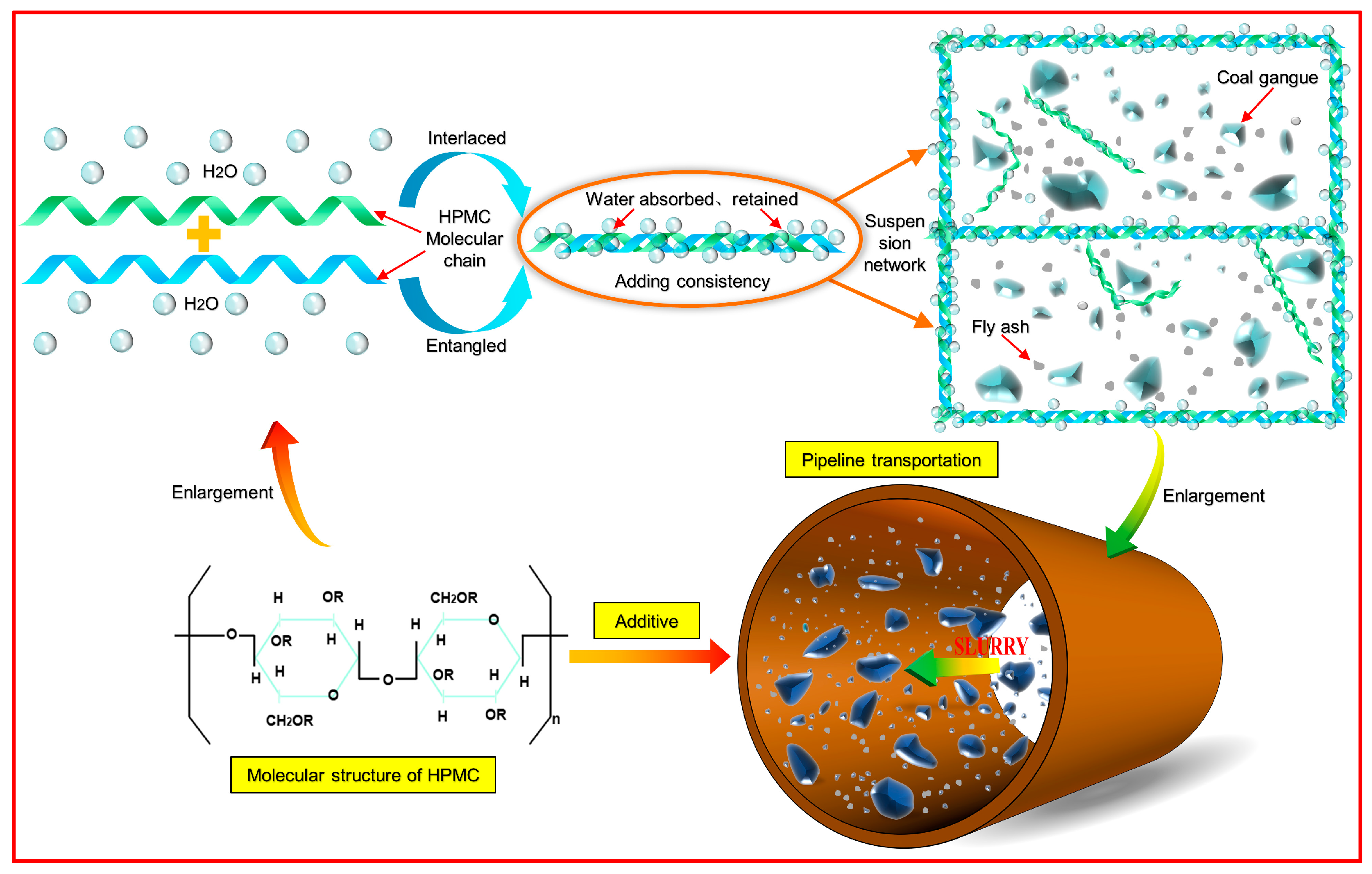
2.1. Analysis of Microfiber Composite Action Mechanism of Suspending Agent
2.2. Suspending Rheological Property Modification Mechanism of Suspending Agent
3. Micro-Morphology Verification
3.1. Types of Hydration Products and Morphology
3.2. Internal Microstructural Development Characteristics
4. Numerical Simulation of Pipeline Transportation
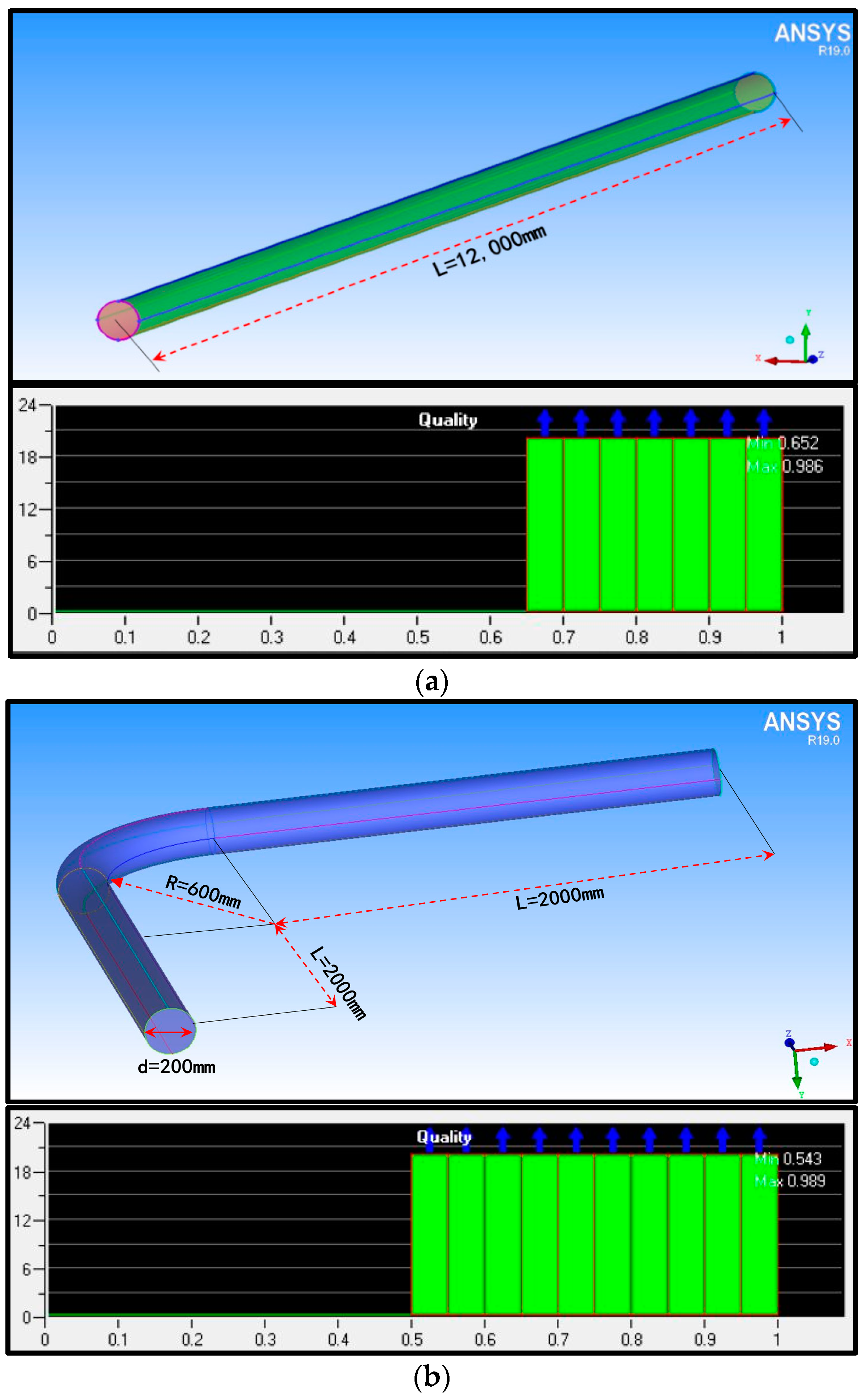
4.1. Numerical Model Establishment
4.2. Solution Setup
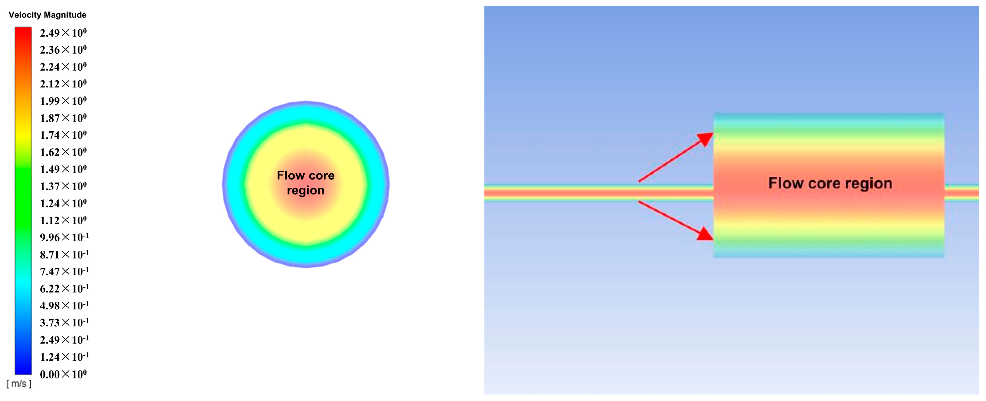
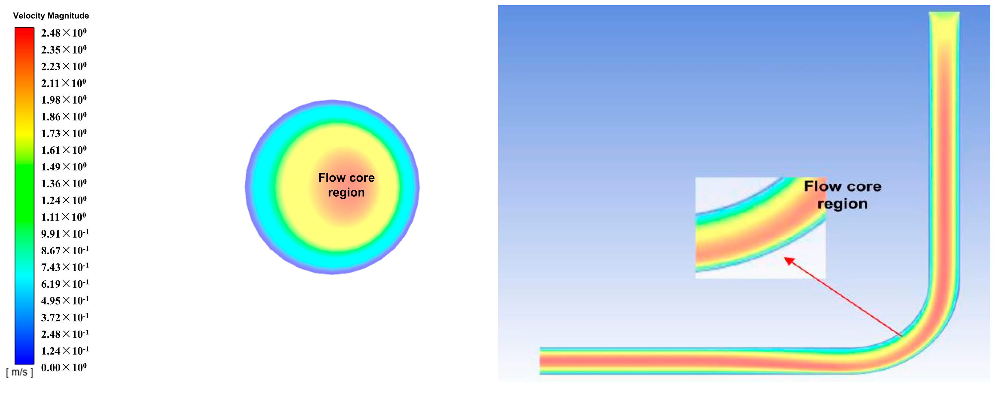
4.3. Numerical Simulation Results
5. Conclusions
Author Contributions
Funding
Data Availability Statement
Conflicts of Interest
References
- Qian, M.G.; Xu, J.L.; Wang, J.C. Further on the sustainable mining of coal. J. China Coal Soc. 2018, 43, 1–13. [Google Scholar]
- Liu, J.G.; Li, X.W.; He, T. Application status and prospect of backfill mining in Chinese coal mines. J. China Coal Soc. 2020, 45, 141–150. [Google Scholar]
- Xu, J.L. Research and progress of coal mine green mining in 20 years. Coal Sci. Technol. 2020, 48, 1–15. [Google Scholar]
- Zhang, J.X.; Zhang, O.; Zhou, N.; Li, M.; Huang, P.; Li, B.Y. Research progress and prospect of coal based solid waste fillinging mining technology. J. China Coal Soc. 2022, 47, 4167–4181. [Google Scholar]
- Yu, R.C. New challenges of cemented filling technology in metal mines-Speech at the 10th China Filling Mining Technology and Equipment Conference. Min. R D 2020, 40, 1. [Google Scholar]
- Yu, R.C.; Liu, C.; Zhu, R.J.; Li, S.H.; He, X.C. Mine information model-the development direction of mining informatization. China Mine Eng. 2018, 47, 1–3+13. [Google Scholar]
- Li, T. Study on Flow Characteristics of High Concentration Cemented Filling Slurry of Coal Gangue; China University of Mining and Technology: Beijing, China, 2022. [Google Scholar]
- Li, T.; Yang, T.; Liu, J.C.; Liu, Z.J.; Yang, T.Y. Study on the suspension state stability of coal-based solid waste filling slurry of long-distance pipeline transportation. Coal Sci. Technol. 2024, 1–14. [Google Scholar]
- Gu, W.Z.; Yang, B.G.; Zhu, L.; Zhao, M.H. Study on spatial characteristics of gangue slurry filling mining and engineering practice. J. Min. Sci. Technol. 2023, 8, 409–418. [Google Scholar]
- Li, T.; Wang, X.L.; Li, M.; Nan, D.Y.; Shan, Q.Y.; Chen, W.X. Synergy between suspending agent and air entraning agent in cement slurry. Rev. Rom. Mater. 2020, 50, 344–353. [Google Scholar]
- Yang, J. Coal Gangue Particle Suspension Study with High-Concentration Cemented Backfilling on Coal Mine; China University of Mining and Technology: Beijing, China, 2022. [Google Scholar]
- Yang, B.G.; Yang, J.; Yu, Y.; Li, D.; Cheng, K. Study on proportioning test of a new cementing filling material and hydration mechanism. J. Min. Sci. Technol. 2017, 2, 475–488. [Google Scholar]
- Zhang, K.F.; Yang, B.G.; Yang, H.G.; Yuan, W.M.; Zhang, Y.N. Experiment Research on High Concentration Cementation Stowing Material in Dongpang Coal Mine. Coal Sci. Technol. 2013, 41, 60–63. [Google Scholar]
- Wang, P.M.; Zhao, G.R.; Zhang, G.F. Mechanism on Water Retention and Thickening of Cellulose Ethers in Fresh Mortars. J. Chin. Ceram. Soc. 2017, 45, 1190–1196. [Google Scholar]
- Zhu, Y.M.; Zhang, Y.; Jiang, Z.W. Effect of Hydroxypropyl Methyl cellulose Ether on Properties of 3D Printing Mortar. J. Build. Mater. 2021, 24, 1124–1130. [Google Scholar]
- Xu, X.; Hao, Y.; Zheng, C.Z. Effect of cellulose ether on the water retention performance of ordinary mortar. China Concr. Cem. Prod. 2017, 4, 69–71. [Google Scholar]
- Brachaczek, W. Influence of Cellulose Ethers on the Consistency, Water Retention and Adhesion of Renovating Plasters. Waclaw Brachaczek IOP Conf. Ser. Mater. Sci. Eng 2019, 471, 032020. [Google Scholar] [CrossRef]
- Batista, I.L.R.; Cabral, K.C.; de Souza, W.R.M.; de Sousa Fontes, A.É.M.; Martinelli, A.E. Influence of hydroxypropyl methyl cellulose (HPMC) on thermal and mechanical performance of cementitious rendering mortars. Mater. Struct. 2024, 57, 25. [Google Scholar] [CrossRef]
- Zhang, Y. Modification and Mechanism of Cement-Based Materials by Cellulose Ether and Latex Powder; Beijing University of civil Engineering and Architecture: Beijing, China, 2022. [Google Scholar]
- Huai, Y.S. Study on Filling Material and Flow Law of Variable Concentration and Large Amount of Fly Ash; China University of Mining and Technology: Beijing, China, 2017. [Google Scholar]
- Wasp, E.J. Solid-Liquid Flow Slurry Pipeline Transportation; Trans Tech Publications: Stafa-Zurich, Switzerland, 1977. [Google Scholar]
- Wang, S.Z.; Sun, P.; Liu, D.Z. Slurry Pipeline Transportation of Granular Materials; Ocean Press: Beijing, China, 1998. [Google Scholar]
- Li, T.; Chen, X.; Liu, Z.; Jiang, W.; Min, H. Study on the suspending mechanism of gangue particle in coal-based solid waste slurry. Alex. Eng. J. 2024, 107, 583–590. [Google Scholar] [CrossRef]
- Soumik, D.; Mona, S.A.; Debadutta, D. Mechanistic insight into the synergistic role of the dual-surfactant system as a green solvent for deoximation reaction: An experimental and computational analysis. J. Mol. Liq. 2024, 400, 124559. [Google Scholar]
- Das, D.; Mohapatra, R.K.; Parhi, P.K.; Sarangi, A.K.; Sahu, R.; Barik, S.R. Sustainable and efficient route for the regeneration of carbonyl compounds from oximes using aqueous extract of sapindus laurifolia under microwave radiation. ACS Omega 2020, 5, 7716–7721. [Google Scholar] [CrossRef]
- Wang, H.F.; Yan, H.D.; Mei, Z. Effect of HPMC on the Piezoresistivity of Smart Concrete Aggregate with Z Shape. J. Wuhan Univ. Technol. (Mater. Sci.) 2020, 35, 768–777. [Google Scholar] [CrossRef]
- Chen, M.; Li, L.; Zheng, Y.; Zhao, P.Q.; Lu, L.C.; Cheng, X. Rheological and mechanical properties of admixtures modified 3D printing sulphoaluminate cementitious materials. Constr. Build. Mater. 2018, 189, 601–611. [Google Scholar] [CrossRef]
- Zheng, W.Y. Study on Effect of Suspending Agent on Conveying Performance of High Concentration Cemented Filling Slurry in Coal Mine; China University of Mining and Technology: Beijing, China, 2017. [Google Scholar]
- Gao, R.; Wang, W.; Xiong, X.; Li, J.; Xu, C. Effect of curing temperature on the mechanical properties and pore structure of cemented backfill materials with waste rock-tailings. Constr. Build. Mater. 2023, 409, 133850. [Google Scholar] [CrossRef]
- Gao, R.; Wang, W.; Zhou, K.; Zhao, Y.; Yang, C.; Ren, Q. Optimization of a Multiphase Mixed Flow Field in Backfill Slurry Preparation Based on Multiphase Flow Interaction. Acs Omega 2023, 8, 34698–34709. [Google Scholar] [CrossRef] [PubMed]
- Gao, R.; Zhou, K.; Zhou, Y.; Yang, C. Research on the fluid characteristics of cemented backfill pipeline transportation of mineral processing tailings. Alex. Eng. J. 2020, 59, 4409–4426. [Google Scholar] [CrossRef]


| Group | Cement (%) | Fly Ash (%) | Coal Gangue (%) | Water (%) | Slurry Mass Concentration (%) | Suspending Agent (%) |
|---|---|---|---|---|---|---|
| A1 | 12 | 19.5 | 43.7 | 24.8 | 75.2 | 0 |
| A2 | 12 | 19.5 | 43.7 | 24.8 | 75.2 | 0.025 |
| A3 | 12 | 19.5 | 43.7 | 24.8 | 75.2 | 0.03 |
| A4 | 12 | 19.5 | 43.7 | 24.8 | 75.2 | 0.035 |
| A5 | 12 | 19.5 | 43.7 | 24.8 | 75.2 | 0.04 |
| t | 0 | 1 | 2 | 3 | 4 |
|---|---|---|---|---|---|
| corresponding test time | 0 min | 30 min | 60 min | 90 min | 120 min |
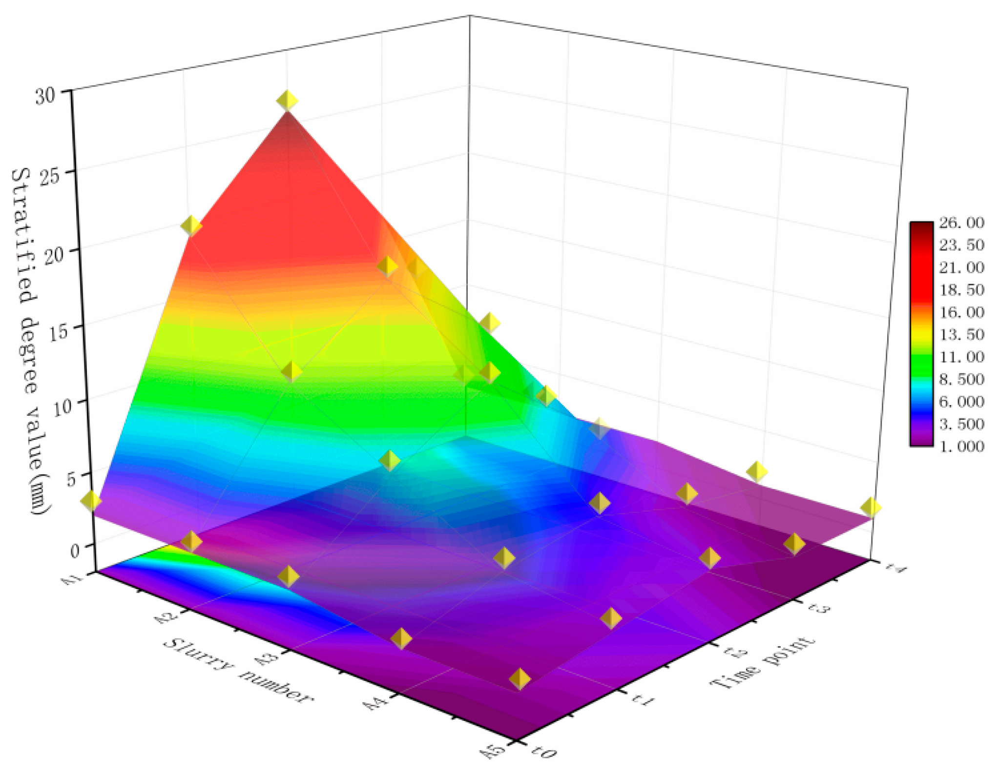
| Group | Layering Degree Value ft (mm) | |||||
|---|---|---|---|---|---|---|
| f0 | f1 | f2 | f3 | f4 | FP | |
| A1 | 2 | 19 | 26 | 17 | 2 | 24 |
| A2 | 2 | 11 | 16 | 11 | 2 | 14 |
| A3 | 2 | 7 | 11 | 6 | 2 | 9 |
| A4 | 1 | 3 | 4 | 2 | 1 | 3 |
| A5 | 1 | 2 | 3 | 1 | 1 | 2 |
| Group | The Value of Time-Loss Rate and Average Time-Loss Rate of Layering Degree (%) | ||||
|---|---|---|---|---|---|
| LossF1 | LossF2 | LossF3 | LossF4 | LossFP | |
| A1 | 850.0 | 36.8 | 34.6 | 88.2 | 252.4 |
| A2 | 450.0 | 45.5 | 31.3 | 81.8 | 152.1 |
| A3 | 250.0 | 57.1 | 45.5 | 66.7 | 104.8 |
| A4 | 200.0 | 33.3 | 50.0 | 50.0 | 83.3 |
| A5 | 100.0 | 50.0 | 66.7 | 0.0 | 54.2 |
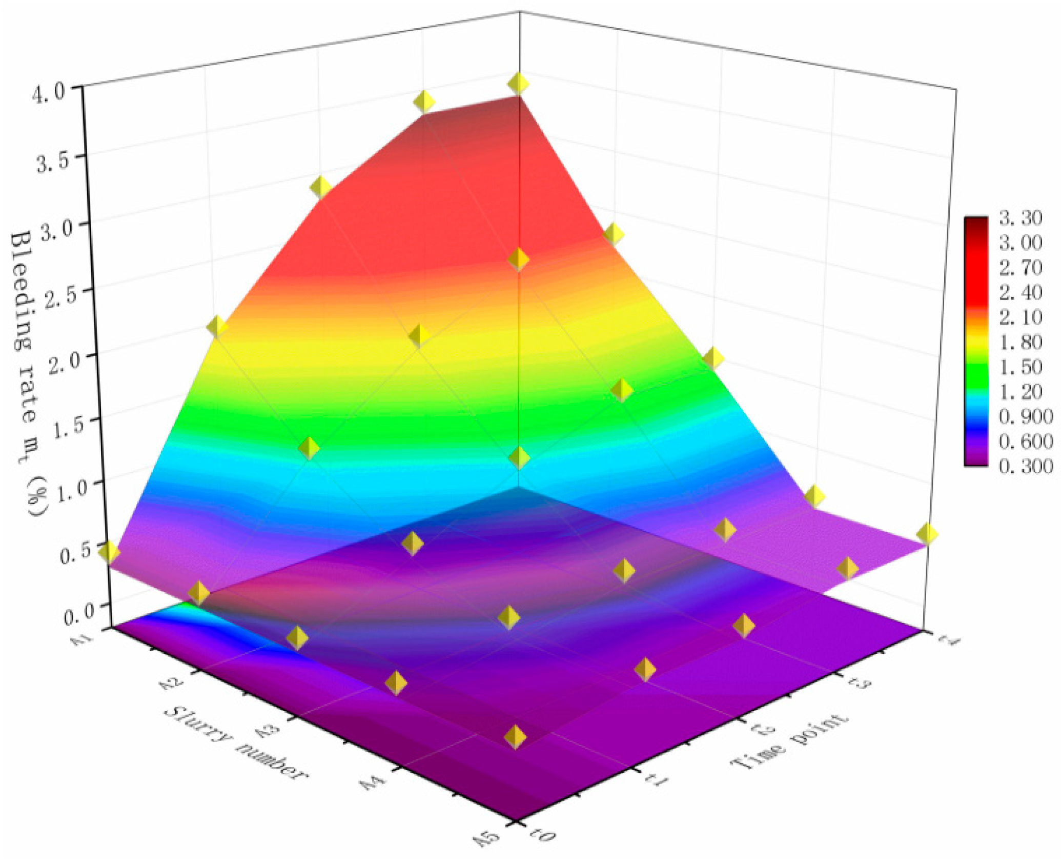
| Group | The Value of Bleeding Rate mt (%) | |||||
|---|---|---|---|---|---|---|
| m0 | m1 | m2 | m3 | m4 | MP | |
| A1 | 0.3 | 1.9 | 2.8 | 3.3 | 3.3 | 3.0 |
| A2 | 0.3 | 1.2 | 1.8 | 2.2 | 2.2 | 1.9 |
| A3 | 0.3 | 0.7 | 1.1 | 1.4 | 1.4 | 1.1 |
| A4 | 0.3 | 0.4 | 0.5 | 0.5 | 0.5 | 0.2 |
| A5 | 0.3 | 0.4 | 0.4 | 0.5 | 0.5 | 0.2 |
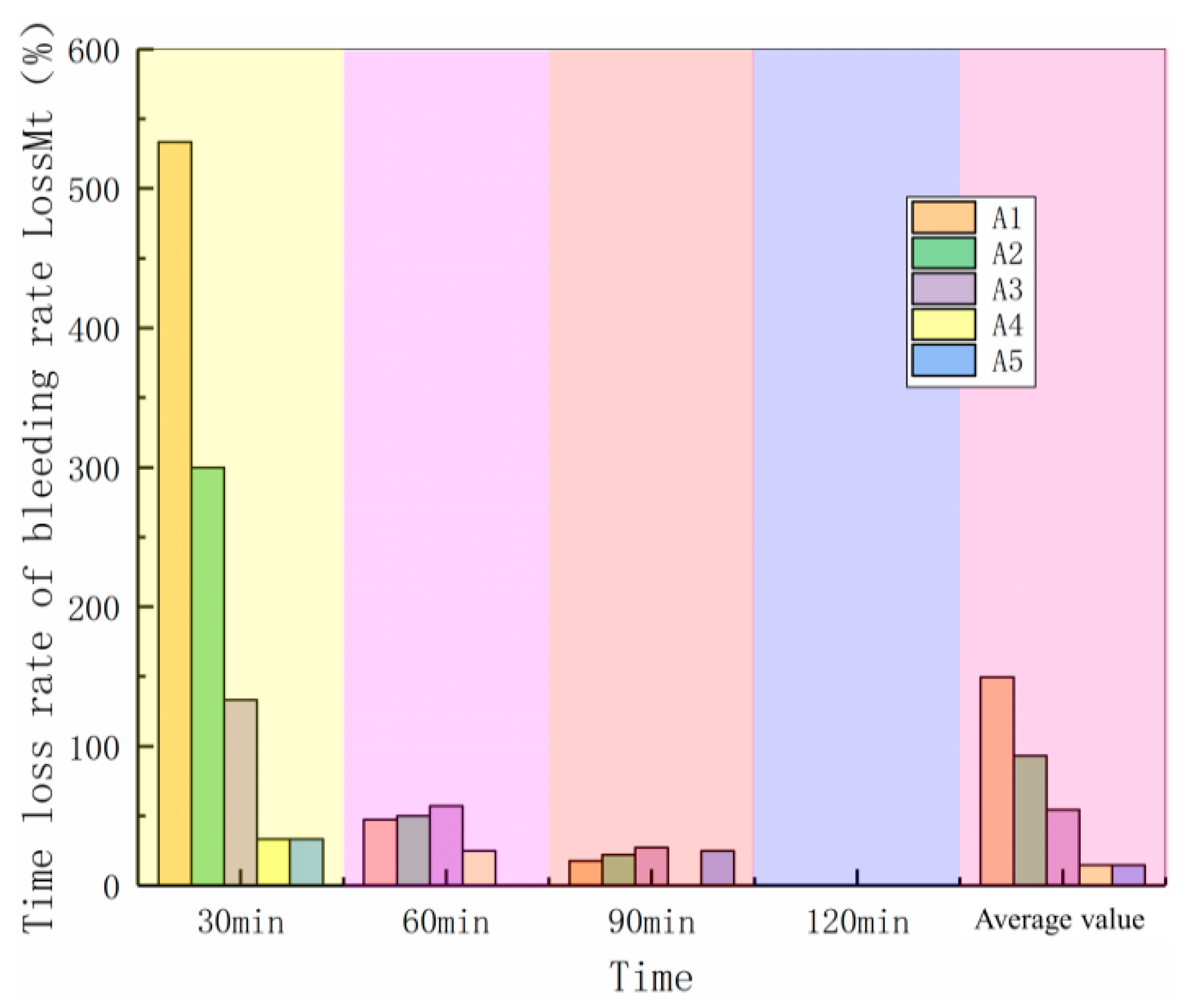
| Group | The Value of Time-Loss Rate and Average Time-Loss Rate of Bleeding Rate (%) | ||||
|---|---|---|---|---|---|
| LossM1 | LossM2 | LossM3 | LossM4 | LossMP | |
| A1 | 533.3 | 47.4 | 17.9 | 0.0 | 149.6 |
| A2 | 300.0 | 50.0 | 22.2 | 0.0 | 93.1 |
| A3 | 133.3 | 57.1 | 27.3 | 0.0 | 54.4 |
| A4 | 33.3 | 25.0 | 0.0 | 0.0 | 14.6 |
| A5 | 33.3 | 0.0 | 25.0 | 0.0 | 14.6 |
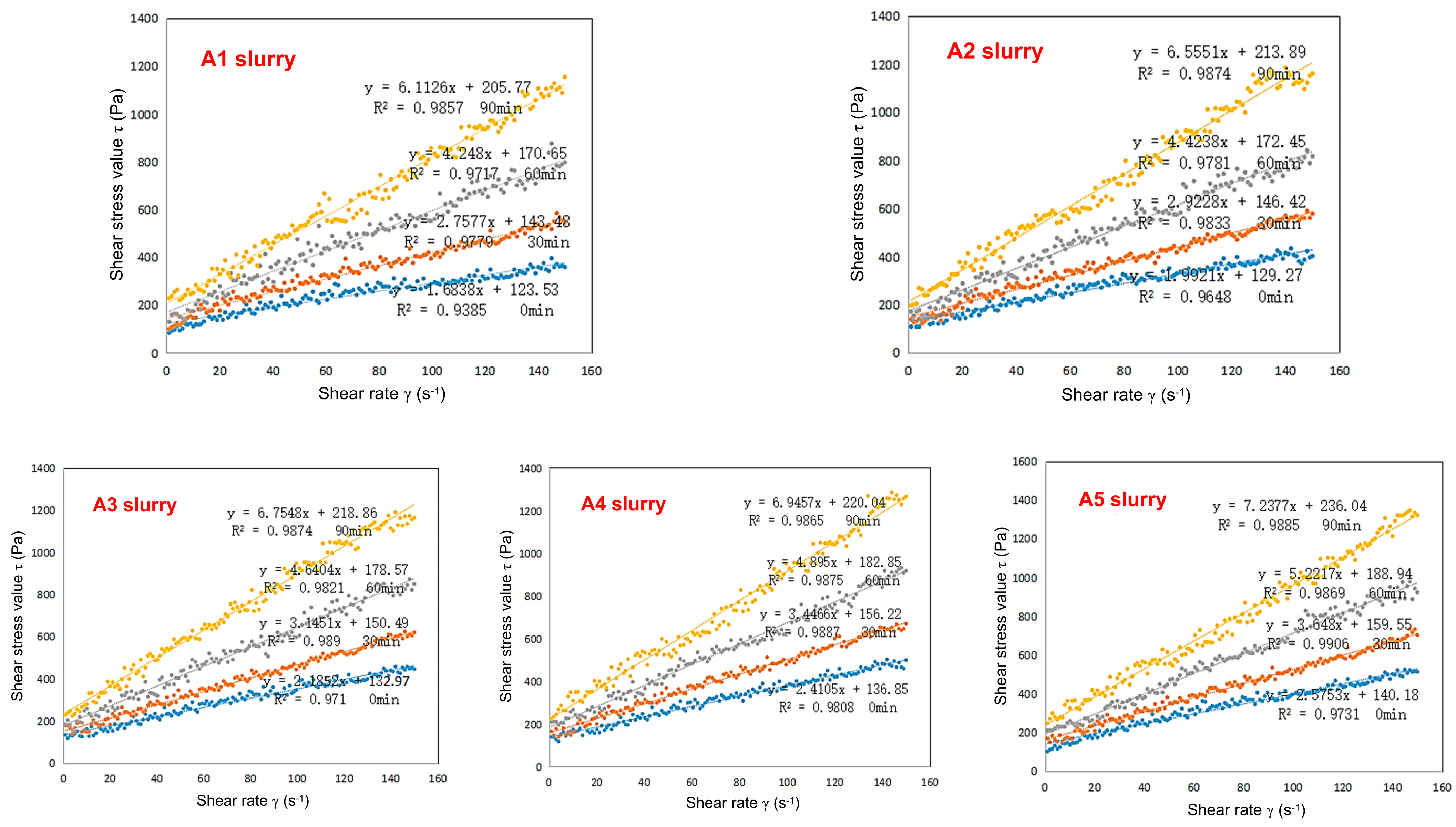
| Reposing time/min | Rheological Property Indexes | A1 Slurry | A2 Slurry | A3 Slurry | A4 Slurry | A5 Slurry |
|---|---|---|---|---|---|---|
| 0 | η/(Pa·s) | 1.68 | 1.99 | 2.19 | 2.41 | 2.58 |
| τ0/Pa | 123.53 | 129.27 | 132.97 | 136.85 | 140.18 | |
| n | 1 | 1 | 1 | 1 | 1 | |
| R2 | 0.9385 | 0.9648 | 0.971 | 0.9808 | 0.9731 | |
| settling state | no settlement | no settlement | no settlement | no settlement | no settlement | |
| rheological equation | y = 1.68x + 123.53 | y = 1.99x + 129.27 | y = 2.19x + 132.97 | y = 2.41x + 136.85 | y = 2.58x + 140.18 | |
| 30 | η/(Pa·s) | 2.76 | 2.92 | 3.15 | 3.45 | 3.65 |
| τ0/Pa | 143.48 | 146.42 | 150.49 | 156.22 | 159.55 | |
| n | 1 | 1 | 1 | 1 | 1 | |
| R2 | 0.9779 | 0.9833 | 0.989 | 0.9887 | 0.9906 | |
| settling state | significant settlement | general settlement | general settlement | no settlement | no settlement | |
| rheological equation | y = 2.76x + 143.48 | y = 2.92x + 146.42 | y = 3.15x + 150.49 | y = 3.45x + 156.22 | y = 3.65x + 159.55 | |
| 60 | η/(Pa·s) | 4.25 | 4.42 | 4.64 | 4.9 | 5.22 |
| τ0/Pa | 170.65 | 172.45 | 178.57 | 182.85 | 188.94 | |
| n | 1 | 1 | 1 | 1 | 1 | |
| R2 | 0.9717 | 0.9781 | 0.9821 | 0.9875 | 0.9869 | |
| settling state | significant settlement | significant settlement | significant settlement | no settlement | no settlement | |
| rheological equation | y = 4.25x + 170.65 | y = 4.42x + 172.45 | y = 4.64x + 178.57 | y = 4.9x + 182.85 | y = 5.22x + 188.94 | |
| 90 | η/(Pa·s) | 6.11 | 6.56 | 6.75 | 6.95 | 7.24 |
| τ0/Pa | 205.77 | 213.89 | 218.86 | 220.04 | 236.04 | |
| n | 1 | 1 | 1 | 1 | 1 | |
| R2 | 0.9857 | 0.9874 | 0.9874 | 0.9865 | 0.9885 | |
| settling state | significant settlement | significant settlement | significant settlement | no settlement | no settlement | |
| rheological equation | y = 6.11x + 205.77 | y = 6.56x + 213.89 | y = 6.75x + 218.86 | y = 6.95x + 220.04 | y = 7.24x + 236.04 | |
| 120 | η/(Pa·s) | - | - | - | - | - |
| τ0/Pa | - | - | - | - | - | |
| n | - | - | - | - | - | |
| R2 | - | - | - | - | - | |
| settling state | significant settlement | significant settlement | significant settlement | no settlement | no settlement | |
| rheological equation | - | - | - | - | - |
Disclaimer/Publisher’s Note: The statements, opinions and data contained in all publications are solely those of the individual author(s) and contributor(s) and not of MDPI and/or the editor(s). MDPI and/or the editor(s) disclaim responsibility for any injury to people or property resulting from any ideas, methods, instructions or products referred to in the content. |
© 2024 by the authors. Licensee MDPI, Basel, Switzerland. This article is an open access article distributed under the terms and conditions of the Creative Commons Attribution (CC BY) license (https://creativecommons.org/licenses/by/4.0/).
Share and Cite
Li, T.; Yang, T.; Min, H.; Cao, M.; Hu, J. Experimental Study on the Suspending Mechanism of Suspending Agent in Coal-Based Solid Waste Slurry for Long-Distance Pipeline Transportation. Processes 2024, 12, 1937. https://doi.org/10.3390/pr12091937
Li T, Yang T, Min H, Cao M, Hu J. Experimental Study on the Suspending Mechanism of Suspending Agent in Coal-Based Solid Waste Slurry for Long-Distance Pipeline Transportation. Processes. 2024; 12(9):1937. https://doi.org/10.3390/pr12091937
Chicago/Turabian StyleLi, Tao, Tao Yang, Heng Min, Min Cao, and Jingyan Hu. 2024. "Experimental Study on the Suspending Mechanism of Suspending Agent in Coal-Based Solid Waste Slurry for Long-Distance Pipeline Transportation" Processes 12, no. 9: 1937. https://doi.org/10.3390/pr12091937
APA StyleLi, T., Yang, T., Min, H., Cao, M., & Hu, J. (2024). Experimental Study on the Suspending Mechanism of Suspending Agent in Coal-Based Solid Waste Slurry for Long-Distance Pipeline Transportation. Processes, 12(9), 1937. https://doi.org/10.3390/pr12091937