
Numerical Study on the Energy Harvesting Performance of a Flapping Foil with Attached Flaps


Abstract
1. Introduction
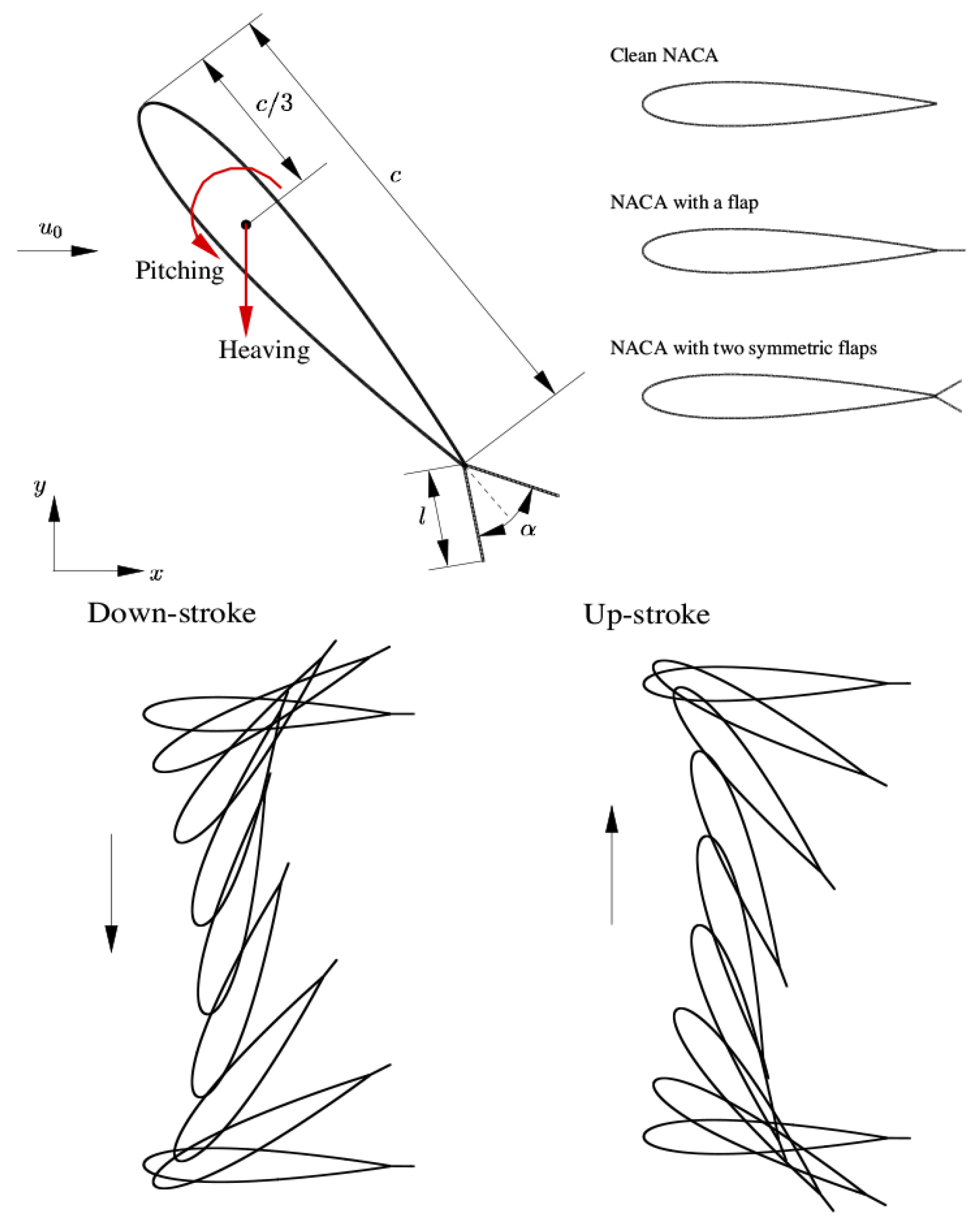
2. Physical Problem
3. Numerical Methods
3.1. LBM for the Fluid Flow
3.2. The IB Method for FSI
4. Results and Discussions
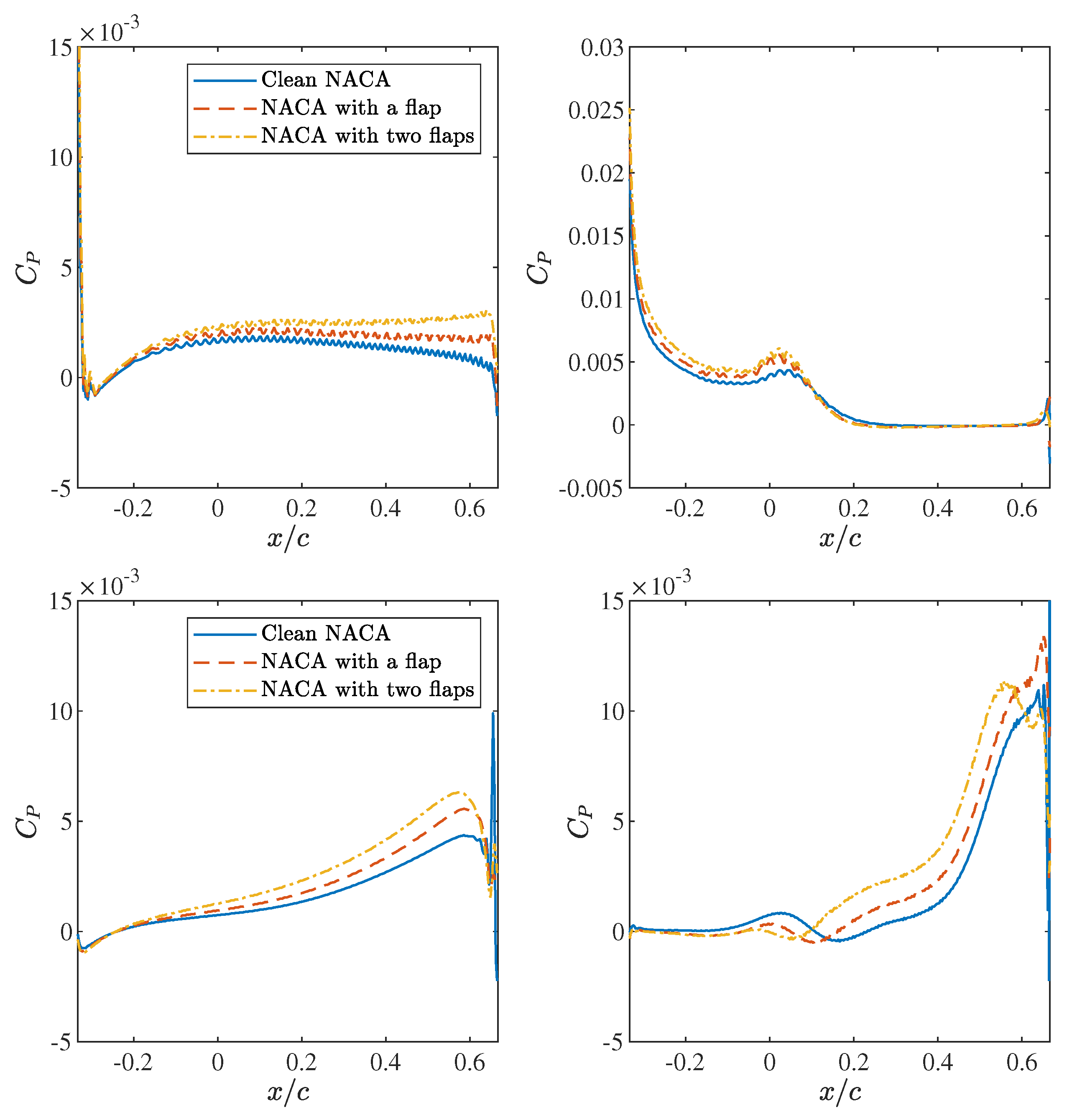
4.1. Enhancement Effects of the Flap
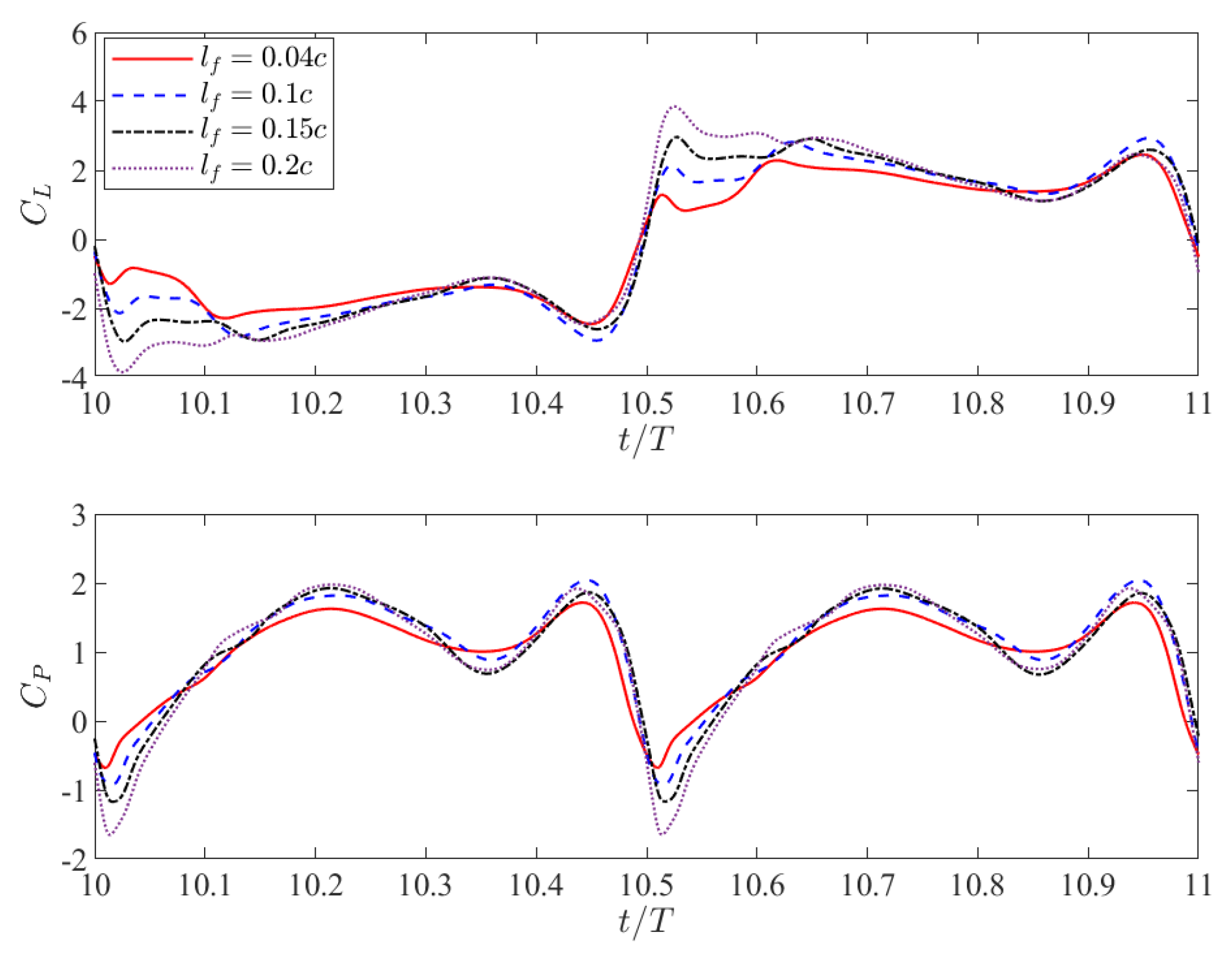
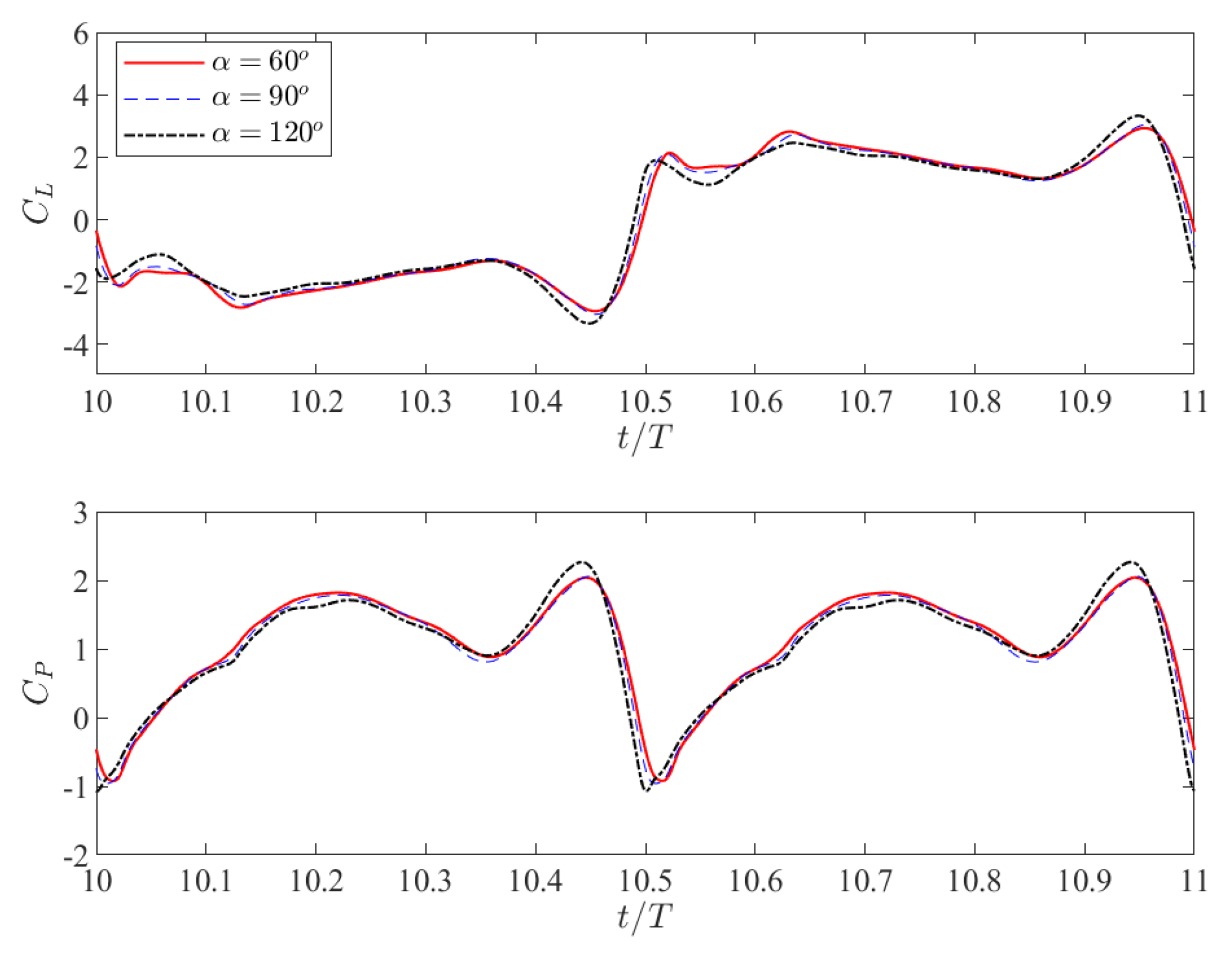
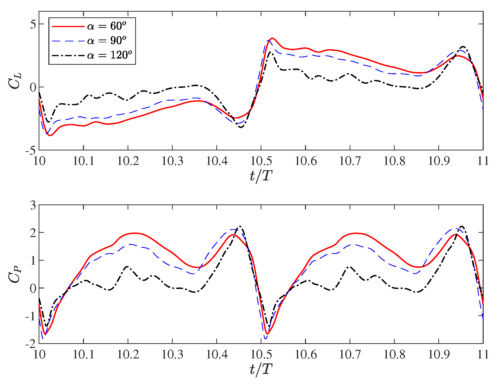
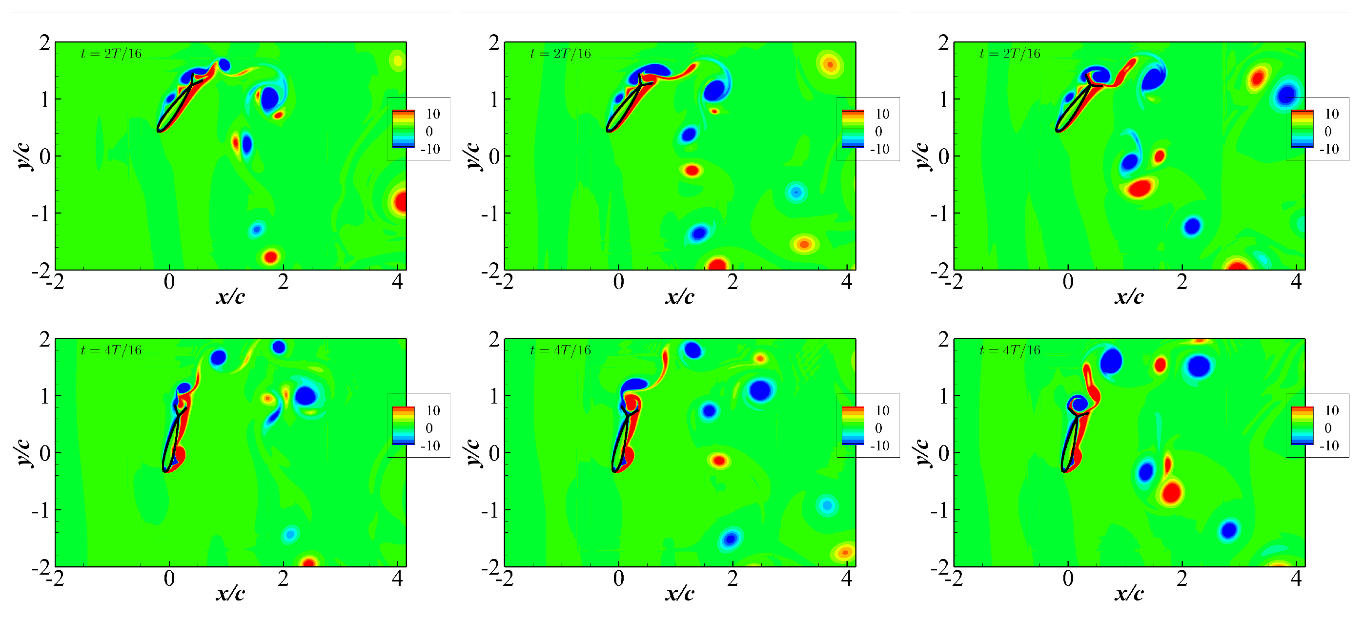
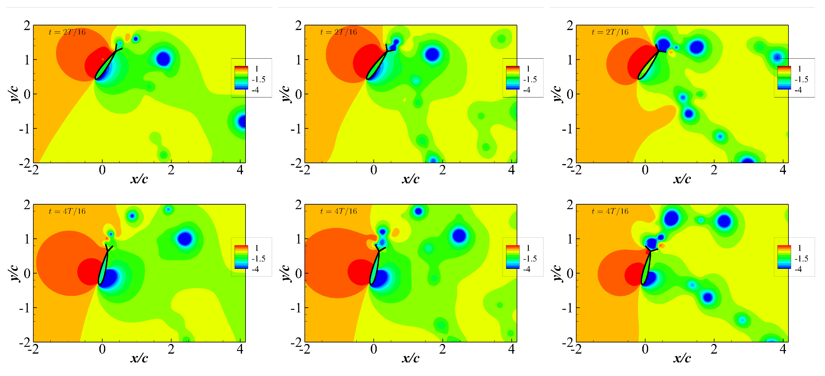
4.2. Effects of the Flap Length and the Angle between the Two Symmetric Flaps
5. Conclusions
Author Contributions
Funding
Data Availability Statement
Conflicts of Interest
Abbreviations
| CFD | Computational fluid dynamics |
| DVM | Discrete vortex method |
| FSI | Fluid–structure interaction |
| IBM | Immersed boundary method |
| LBM | Lattice Boltzmann method |
| LEV | Leading edge vortex |
| MRT | Multi-relaxation time |
| UPM | Unsteady panel method |
References
- Olabi, A.; Abdelkareem, M.A. Renewable energy and climate change. Renew. Sustain. Energy Rev. 2022, 158, 112111. [Google Scholar] [CrossRef]
- Yang, X.; Pang, J.; Teng, F.; Gong, R.; Springer, C. The environmental co-benefit and economic impact of China’s low-carbon pathways: Evidence from linking bottom-up and top-down models. Renew. Sustain. Energy Rev. 2021, 136, 110438. [Google Scholar] [CrossRef]
- Lewis, M.; Neill, S.; Robins, P.; Hashemi, M. Resource assessment for future generations of tidal-stream energy arrays. Energy 2015, 83, 403–415. [Google Scholar] [CrossRef]
- Young, J.; Lai, J.C.; Platzer, M.F. A review of progress and challenges in flapping foil power generation. Prog. Aerosp. Sci. 2014, 67, 2–28. [Google Scholar] [CrossRef]
- McKinney, W.; DeLaurier, J. Wingmill: An oscillating-wing windmill. J. Energy 1981, 5, 109–115. [Google Scholar] [CrossRef]
- Davids, S.T. A Computational and Experimental Investigation of a Flutter Generator. Ph.D. Thesis, Naval Postgraduate School, Monterey, CA, USA, 1999. [Google Scholar]
- Lindsey, K. A Feasibility Study of Oscillating-Wing Power Generators. Ph.D. Thesis, Naval Postgraduate School, Monterey, CA, USA, 2002. [Google Scholar]
- Liu, Z.; Lai, J.C.; Young, J.; Tian, F.B. Discrete vortex method with flow separation corrections for flapping-foil power generators. AIAA J. 2017, 55, 410–418. [Google Scholar] [CrossRef]
- Kinsey, T.; Dumas, G. Parametric study of an oscillating airfoil in a power-extraction regime. AIAA J. 2008, 46, 1318–1330. [Google Scholar] [CrossRef]
- Liu, Z.; Bhattacharjee, K.S.; Tian, F.B.; Young, J.; Ray, T.; Lai, J.C. Kinematic optimization of a flapping foil power generator using a multi-fidelity evolutionary algorithm. Renew. Energy 2019, 132, 543–557. [Google Scholar] [CrossRef]
- Zhu, Q.; Peng, Z. Mode coupling and flow energy harvesting by a flapping foil. Phys. Fluids 2009, 21, 033601. [Google Scholar] [CrossRef]
- Zhu, Q.; Haase, M.; Wu, C.H. Modeling the capacity of a novel flow-energy harvester. Appl. Math. Model. 2009, 33, 2207–2217. [Google Scholar] [CrossRef]
- Timm, K.; Kusumaatmaja, H.; Kuzmin, A.; Shardt, O.; Silva, G.; Viggen, E. The Lattice Boltzmann Method: Principles and Practice; Springer International Publishing AG: Cham, Switzerland, 2016. [Google Scholar]
- Wang, L.; Liu, Z.; Rajamuni, M. Recent progress of lattice Boltzmann method and its applications in fluid-structure interaction. Proc. Inst. Mech. Eng. Part C J. Mech. Eng. Sci. 2023, 237, 2461–2484. [Google Scholar] [CrossRef]
- Liu, Z.; Huang, Q.; Li, Z.; Li, Y.; Feng, X. Partial confinement effects on the performance of a flapping foil power generator. Phys. Fluids 2023, 35, 027108. [Google Scholar] [CrossRef]
- Le, T.Q.; Ko, J.H.; Byun, D. Morphological effect of a scallop shell on a flapping-type tidal stream generator. Bioinspiration Biomimetics 2013, 8, 036009. [Google Scholar] [CrossRef]
- Liu, W.; Xiao, Q.; Cheng, F. A bio-inspired study on tidal energy extraction with flexible flapping wings. Bioinspiration Biomimetics 2013, 8, 036011. [Google Scholar] [CrossRef] [PubMed]
- Hoke, C.M.; Young, J.; Lai, J.C. Enhancing the power-extraction efficiency of a flapping foil by active morphing. AIAA J. 2023, 61, 4056–4069. [Google Scholar] [CrossRef]
- Liu, Z.; Tian, F.B.; Young, J.; Lai, J. Flapping foil power generator performance enhanced with a spring-connected tail. Phys. Fluids 2017, 29, 123601. [Google Scholar] [CrossRef]
- Fang, Z.; Gong, C.; Revell, A.; Chen, G.; Harwood, A.; O’connor, J. Passive separation control of a NACA0012 airfoil via a flexible flap. Phys. Fluids 2019, 31, 101904. [Google Scholar] [CrossRef]
- Wang, L.; Tian, F.B. Sound generated by the flow around an airfoil with an attached flap: From passive fluid–structure interaction to active control. J. Fluids Struct. 2022, 111, 103571. [Google Scholar] [CrossRef]
- Peng, Y.; He, M.; Hu, F.; Mao, Z.; Huang, X.; Ding, J. Predictive Modeling of Flexible EHD Pumps using Kolmogorov-Arnold Networks. arXiv 2024, arXiv:2405.07488. [Google Scholar]
- Gupta, R.; Jaiman, R. A hybrid partitioned deep learning methodology for moving interface and fluid–structure interaction. Comput. Fluids 2022, 233, 105239. [Google Scholar] [CrossRef]
- Wang, L.; Tian, F.B. Heat transfer in non-Newtonian flows by a hybrid immersed boundary–Lattice Boltzmann and finite difference method. Appl. Sci. 2018, 8, 559. [Google Scholar] [CrossRef]
- Wang, L.; Tian, F.B. Numerical simulation of flow over a parallel cantilevered flag in the vicinity of a rigid wall. Phys. Rev. E 2019, 99, 053111. [Google Scholar] [CrossRef] [PubMed]
- Guo, Z.; Zheng, C. Analysis of lattice Boltzmann equation for microscale gas flows: Relaxation times, boundary conditions and the Knudsen layer. Int. J. Comput. Fluid Dyn. 2008, 22, 465–473. [Google Scholar] [CrossRef]
- Tian, F.B.; Luo, H.; Zhu, L.; Liao, J.C.; Lu, X.Y. An efficient immersed boundary-lattice Boltzmann method for the hydrodynamic interaction of elastic filaments. J. Comput. Phys. 2011, 230, 7266–7283. [Google Scholar] [CrossRef] [PubMed]
- Yu, D.; Mei, R.; Shyy, W. A multi-block lattice Boltzmann method for viscous fluid flows. Int. J. Numer. Methods Fluids 2002, 39, 99–120. [Google Scholar] [CrossRef]
- Kim, Y.; Peskin, C.S. Penalty immersed boundary method for an elastic boundary with mass. Phys. Fluids 2007, 19, 053103. [Google Scholar] [CrossRef]
- Tian, F.B.; Dai, H.; Luo, H.; Doyle, J.F.; Rousseau, B. Fluid–structure interaction involving large deformations: 3D simulations and applications to biological systems. J. Comput. Phys. 2014, 258, 451–469. [Google Scholar] [CrossRef]
- Mittal, R.; Dong, H.; Bozkurttas, M.; Najjar, F.; Vargas, A.; von Loebbecke, A. A versatile sharp interface immersed boundary method for incompressible flows with complex boundaries. J. Comput. Phys. 2008, 227, 4825–4852. [Google Scholar] [CrossRef]
- Peskin, C.S. The immersed boundary method. Acta Numer. 2002, 11, 479–517. [Google Scholar] [CrossRef]
- Wang, L. Locomotion of a self-propulsive pitching plate in a quiescent viscous fluid. Proc. Inst. Mech. Eng. Part C J. Mech. Eng. Sci. 2021, 235, 342–350. [Google Scholar] [CrossRef]


| Sources | ||||
|---|---|---|---|---|
| Clean NACA | 2.565 | 0.850 | 0.331 | - |
| NACA with a flap | 2.698 | 0.992 | 0.368 | 11.17% |
| NACA with two flaps | 2.753 | 1.092 | 0.397 | 19.94% |
Disclaimer/Publisher’s Note: The statements, opinions and data contained in all publications are solely those of the individual author(s) and contributor(s) and not of MDPI and/or the editor(s). MDPI and/or the editor(s) disclaim responsibility for any injury to people or property resulting from any ideas, methods, instructions or products referred to in the content. |
© 2024 by the authors. Licensee MDPI, Basel, Switzerland. This article is an open access article distributed under the terms and conditions of the Creative Commons Attribution (CC BY) license (https://creativecommons.org/licenses/by/4.0/).
Share and Cite
Wu, S.; Wang, L. Numerical Study on the Energy Harvesting Performance of a Flapping Foil with Attached Flaps. Processes 2024, 12, 1963. https://doi.org/10.3390/pr12091963
Wu S, Wang L. Numerical Study on the Energy Harvesting Performance of a Flapping Foil with Attached Flaps. Processes. 2024; 12(9):1963. https://doi.org/10.3390/pr12091963
Chicago/Turabian StyleWu, Shihui, and Li Wang. 2024. "Numerical Study on the Energy Harvesting Performance of a Flapping Foil with Attached Flaps" Processes 12, no. 9: 1963. https://doi.org/10.3390/pr12091963
APA StyleWu, S., & Wang, L. (2024). Numerical Study on the Energy Harvesting Performance of a Flapping Foil with Attached Flaps. Processes, 12(9), 1963. https://doi.org/10.3390/pr12091963