
Research on the Energy-Absorbing and Cushioning Performance of a New Half-Bowl Ball Rubber Body in Tunnel Support


Abstract
:1. Introduction
2. Materials and Methods
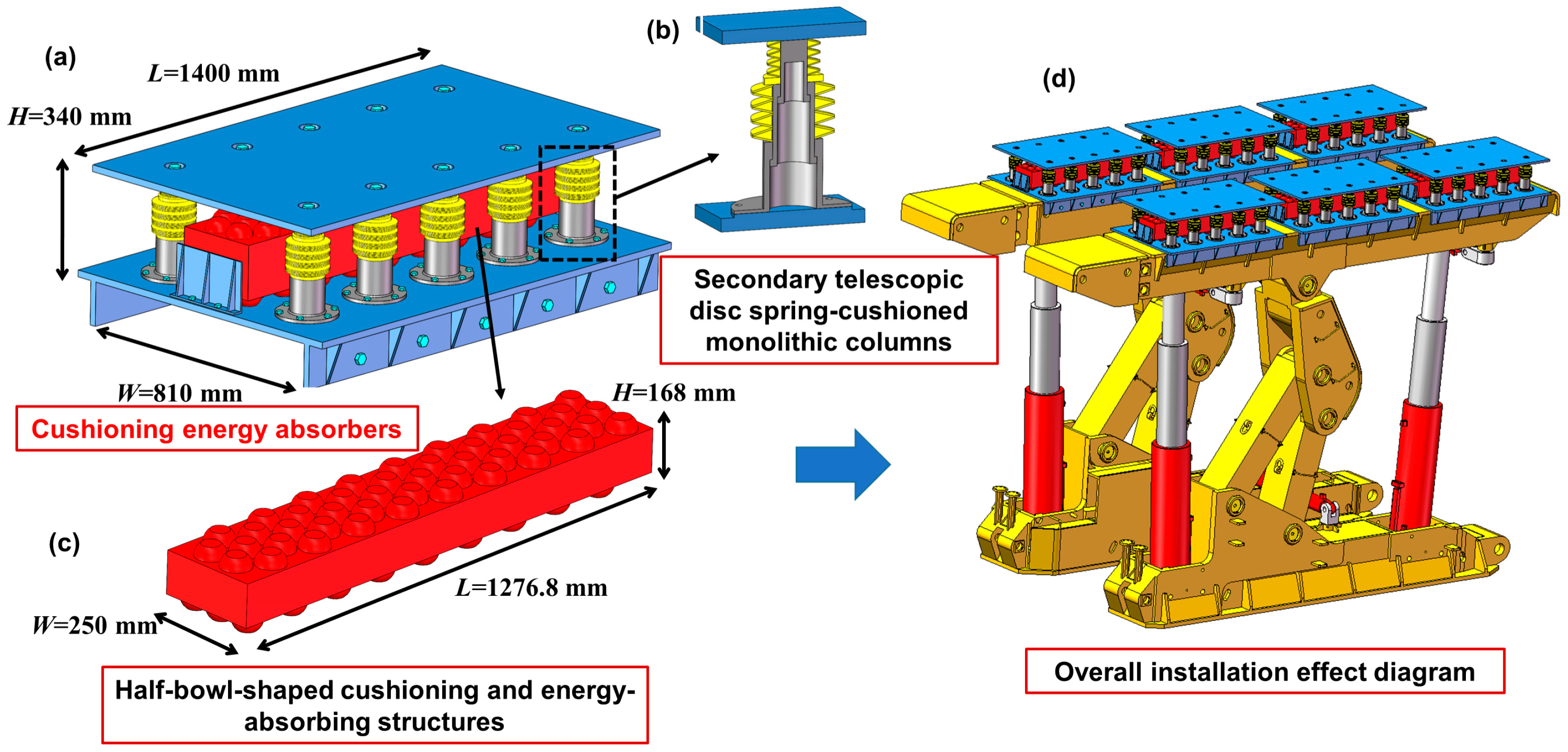
2.1. Cushion Energy Absorber Structure
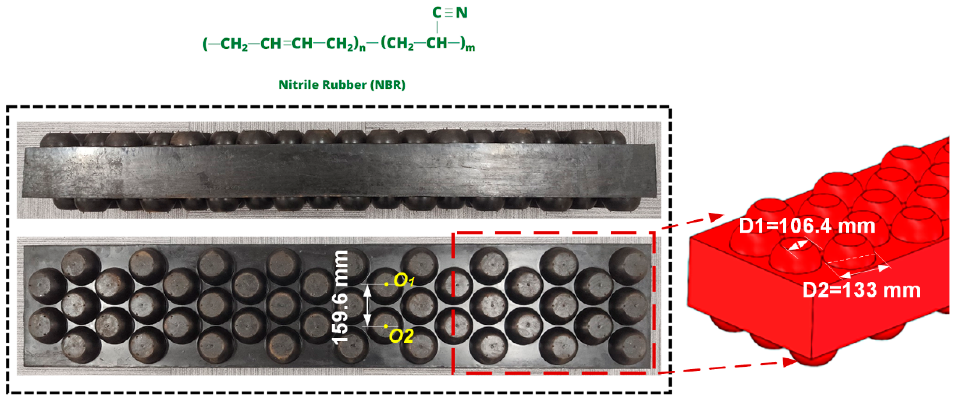
2.2. Half-Bowl-Shaped Energy-Absorbing Rubber Structure
2.3. Dynamical Model
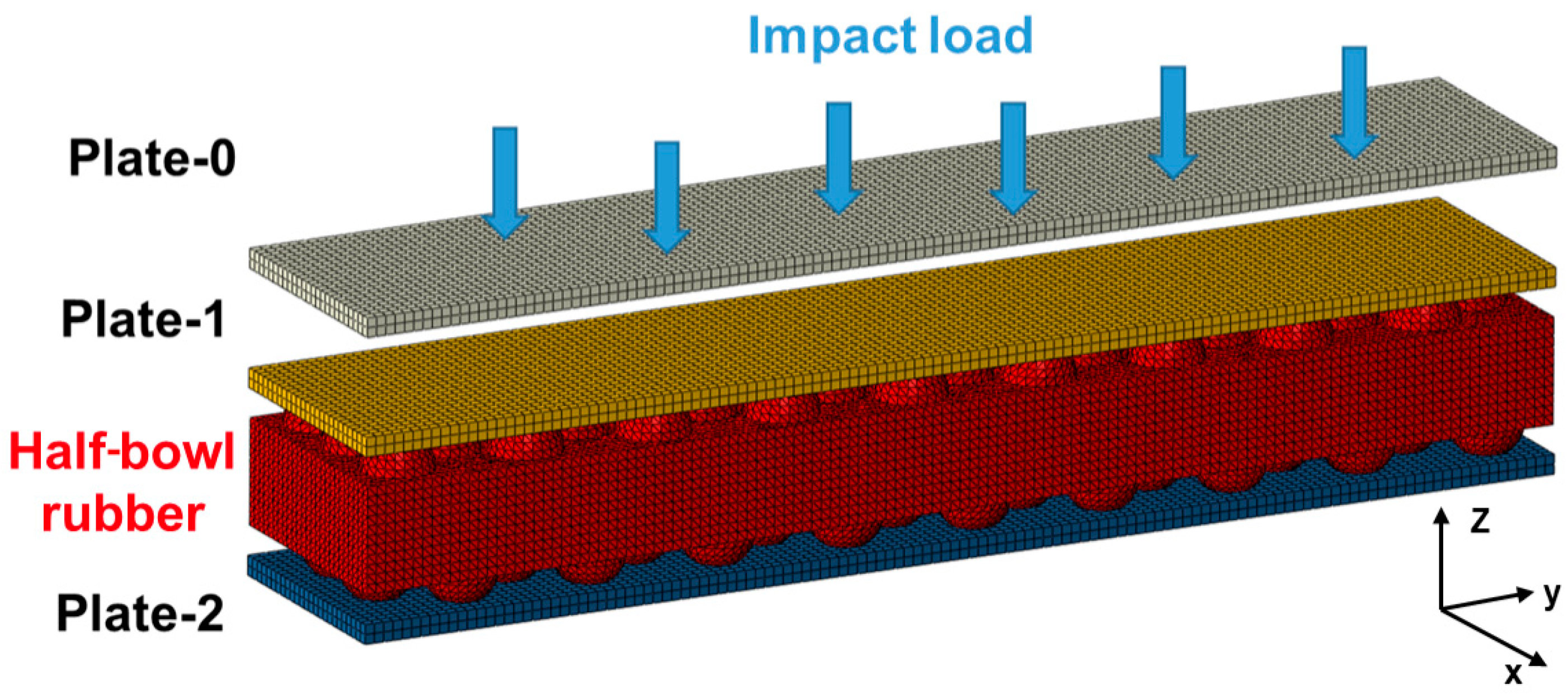
Numerical Modeling
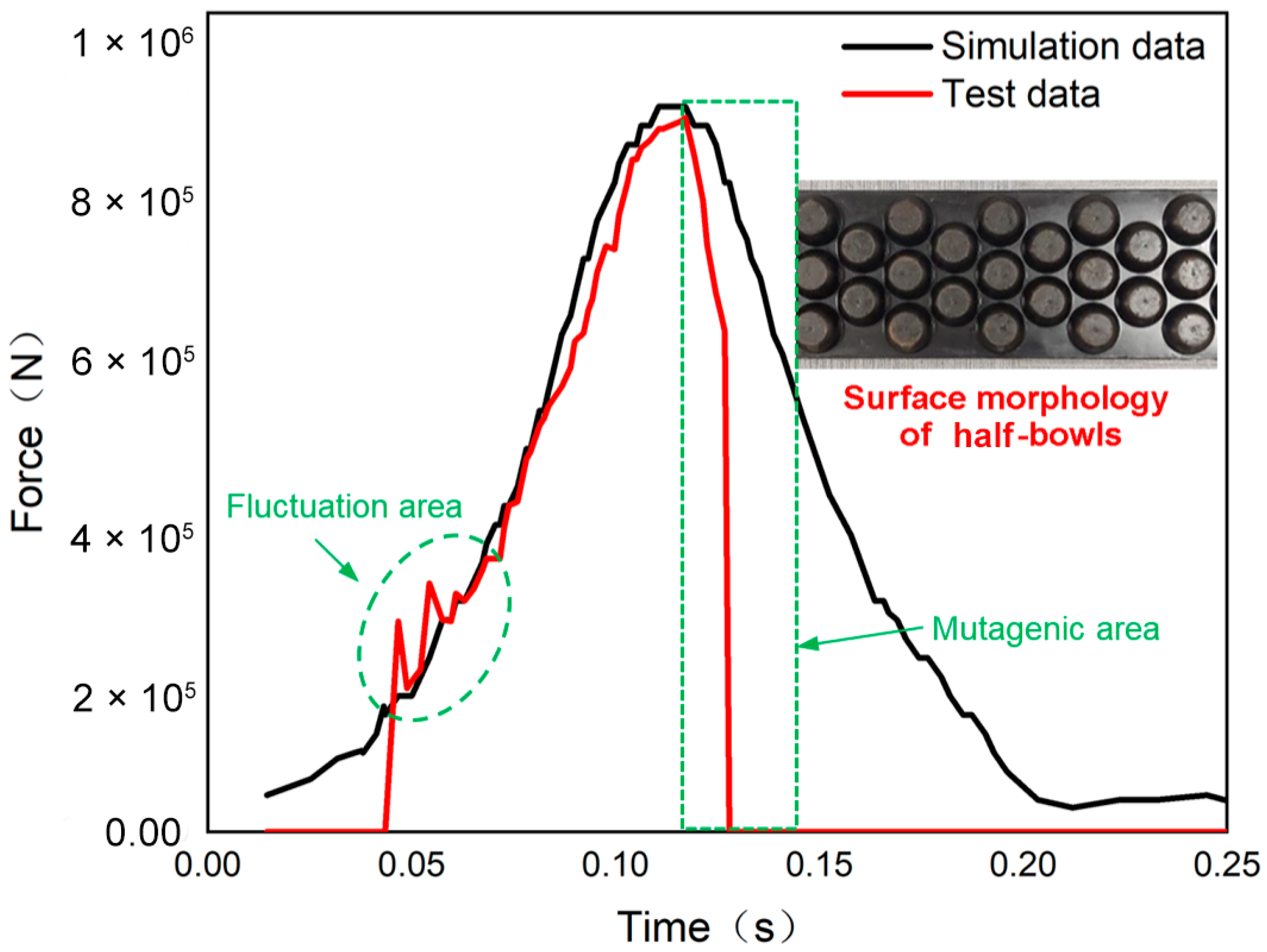
2.4. Impact Test
3. Results and Discussion
3.1. Dynamic Response of Rubber Structures under Different Impact Energies
3.2. Transmission Effects of Pressure
3.3. Energy Absorption in Half-Bowl Ball Rubber Structures
4. Conclusions
- (1)
- The results of this study show that the half-bowl spherical rubber structure is very effective in absorbing external impact energy. Specifically, at 105 J of impact energy, the structure exhibits excellent performance to meet the stringent requirements of mining operations.
- (2)
- The energy-absorbing effect of the rubber structure is mainly realized by converting the impact energy into elastic potential energy, which is then stored in the rubber structure.
- (3)
- An analysis of the relationship between energy absorption, stress distribution, and deformation of the rubber structure and the base plate at varying impact velocities revealed that when the impact speed is within the range of 35 m/s to 50 m/s, the compression amount of the half-bowl structure undergoes the most significant changes. This observation underscores the critical importance of controlling the impact velocity within this range to optimize energy absorption and minimize stress concentrations.
Author Contributions
Funding
Data Availability Statement
Conflicts of Interest
References
- Zhang, Z.; Wu, S.; Cheng, H.; Han, L.; Zhong, G.; Zhang, J. Rockburst simulation tests on structural plane of deep high-stress circular tunnels: A true triaxial test study on several different hard rocks. Theor. Appl. Fract. Mech. 2024, 132, 104473. [Google Scholar] [CrossRef]
- Zhang, Q.; Huo, J.; Yuan, L.; Li, Y.; Yang, F.; Wang, X. A review of rockburst prevention and control methods in tunnels: Graded and classified prevention and control. Bull. Eng. Geol. Environ. 2024, 83, 83. [Google Scholar] [CrossRef]
- Zhao, T.-B.; Guo, W.-Y.; Tan, Y.-L.; Lu, C.-P.; Wang, C.-W. Case histories of rock bursts under complicated geological conditions. Bull. Eng. Geol. Environ. 2018, 77, 1529–1545. [Google Scholar] [CrossRef]
- Ghorbani, M.; Shahriar, K.; Sharifzadeh, M.; Masoudi, R. A critical review on the developments of rock support systems in high stress ground conditions. Int. J. Min. Sci. Technol. 2020, 30, 555–572. [Google Scholar] [CrossRef]
- Liu, X.-Y.; Xu, D.-P.; Jiang, Q.; Ma, X.-D. Excavation response and reinforcement practice of large underground caverns within high-stress hard rock masses: The case of Shuangjiangkou hydropower Station, China. Tunn. Undergr. Space Technol. 2024, 147, 105698. [Google Scholar] [CrossRef]
- Xie, S.; Jiang, Z.; Chen, D.; Wang, E.; Lv, F. A new pressure relief technology by internal hole-making to protect roadway in two sides of deep coal roadway: A case study. Rock Mech. Rock Eng. 2023, 56, 1537–1561. [Google Scholar] [CrossRef]
- Wu, W.; Gong, F.; Ren, L.; He, L. Strain rockburst failure characteristics and mechanism of high stress circular hard rock tunnel triggered by dynamic impact load. Int. J. Rock Mech. Min. Sci. 2023, 171, 105575. [Google Scholar] [CrossRef]
- Zhang, J.; Liu, J.; Yang, G.; Hou, S.; Wang, Y.; He, M.; Yang, J. Study on pressure relief mechanism of hydraulic support in working face under directional roof crack. Arch. Min. Sci. 2023, 68, 103–123. [Google Scholar] [CrossRef]
- Kang, H.; Jiang, P.; Feng, Y.; Gao, F.; Zhang, Z.; Liu, X. Application of large-scale hydraulic fracturing for reducing mining-induced stress and microseismic events: A comprehensive case study. Rock Mech. Rock Eng. 2023, 56, 1399–1413. [Google Scholar] [CrossRef]
- Song, S.; Ren, T.; Dou, L.; Sun, J.; Yang, X.; Tan, L. Fracture features of brittle coal under uniaxial and cyclic compression loads. Int. J. Coal Sci. Technol. 2023, 10, 9. [Google Scholar] [CrossRef]
- Vakili, A.; Sandy, M.; Mathews, M.; Rodda, B. Ground support design under highly stressed conditions. In Ground Support 2013, Proceedings of the Seventh International Symposium on Ground Support in Mining and Underground Construction, Perth, Australia, 13–15 May 2013; Australian Centre for Geomechanics: Crawley, Australia, 2013; pp. 551–564. [Google Scholar] [CrossRef]
- Guo, F.; Zhang, N.; Xie, Z.; Han, C.; Zhang, C.; Yuan, Y.; He, Z.; Liu, J. A three-dimensional supporting technology, optimization and inspiration from a deep coal mine in China. Rock Mech. Rock Eng. 2024, 57, 655–677. [Google Scholar] [CrossRef]
- Kang, H.; Gao, F.; Xu, G.; Ren, H. Mechanical behaviors of coal measures and ground control technologies for China’s deep coal mines–A review. J. Rock Mech. Geotech. Eng. 2023, 15, 37–65. [Google Scholar] [CrossRef]
- Chai, Y.; Dou, L.; Cai, W.; Małkowski, P.; Li, X.; Gong, S.; Bai, J.; Cao, J. Experimental investigation into damage and failure process of coal-rock composite structures with different roof lithologies under mining-induced stress loading. Int. J. Rock Mech. Min. Sci. 2023, 170, 105479. [Google Scholar] [CrossRef]
- Babets, D.; Sdvyzhkova, O.; Hapieiev, S.; Shashenko, O.; Vasyl, V. Multifactorial analysis of a gateroad stability at goaf interface during longwall coal mining–A case study. Min. Miner. Depos. 2023, 17, 9–19. [Google Scholar] [CrossRef]
- Bondarenko, V.; Kovalevska, I.; Sheka, I.; Sachko, R. Results of research on the stability of mine workings, fixed by arched supports made of composite materials, in the conditions of the Pokrovske Mine Administration. IOP Conf. Ser. Earth Environ. Sci. 2023, 1156, 012011. [Google Scholar] [CrossRef]
- Li, C.; Xu, Y.; Ye, Z. Energy dissipation and crushing characteristics of coal-rock-like combined body under impact loading. Chin. J. Geotech. Eng. 2020, 42, 981–988. [Google Scholar] [CrossRef]
- Tang, Z.; Zuo, W.; Gao, K.; Cai, X. Factors influencing the anti-impact performance of a “roadway rock support” system. Front. Earth Sci. 2023, 11, 1117140. [Google Scholar] [CrossRef]
- Ganapathy, V.; Muthukumaran, G.; Sudhagar, P.E.; Rashedi, A.; Norrrahim, M.N.F.; Ilyas, R.A.; Goh, K.L.; Jawaid, M.; Naveen, J. Mechanical properties of cellulose-based multiscale composites: A review. Polym. Compos. 2023, 44, 734–756. [Google Scholar] [CrossRef]
- Jiang, L.; Gu, B.; Hu, H. Auxetic composite made with multilayer orthogonal structural reinforcement. Compos. Struct. 2016, 135, 23–29. [Google Scholar] [CrossRef]
- Tan, Y.; Guo, W.; Xin, H.; Zhao, T.; Yu, F.; Liu, S. Research on key technology of impact ground pressure monitoring and relief in deep coal mining. J. Coal 2019, 44, 160–172. [Google Scholar]
- Yin, T.-B.; Wang, P.; Li, X.-B.; Shu, R.-H.; Ye, Z.-Y. Effects of thermal treatment on physical and mechanical characteristics of coal rock. J. Cent. South Univ. 2016, 23, 2336–2345. [Google Scholar] [CrossRef]
- Zhang, K.; Zhang, Y.; Zhang, S.; Ren, J.; Zhang, L.; Zhang, R.; Cui, Y. Study on the energy evolution mechanism of coal and rock with impact tendency under different strain rates. Sci. Rep. 2023, 13, 13773. [Google Scholar] [CrossRef] [PubMed]
- Xue, X.; Zhang, C.; Chen, W.; Wu, M.; Zhao, J. Study on the impact resistance of honeycomb sandwich structures under low-velocity/heavy mass. Compos. Struct. 2019, 226, 111223. [Google Scholar] [CrossRef]
- Arjangpay, A.; Darvizeh, A.; Tooski, M.Y. Effects of structural characteristics of a bionic dragonfly wing on its low velocity impact resistance. J. Bionic Eng. 2018, 15, 859–871. [Google Scholar] [CrossRef]
- Chen, R.; Liu, J.; Yang, C.; Weitz, D.A.; He, H.; Li, D.; Chen, D.; Liu, K.; Bai, H. Transparent impact-resistant composite films with bioinspired hierarchical structure. ACS Appl. Mater. Interfaces 2019, 11, 23616–23622. [Google Scholar] [CrossRef]
- Wen, J.; Zuo, J.; Wang, Z.; Wen, Z.; Wang, J. Failure mechanism analysis and support strength determination of deep coal mine roadways–A case study. Constr. Build. Mater. 2024, 443, 137704. [Google Scholar] [CrossRef]
- Yao, W.; Liu, G.; Pang, J.; Huang, X. Instability mechanism and surrounding rock control technology of roadway subjected to mining dynamic loading with short distance: A case study of the Gubei Coal Mine in China. Geotech. Geol. Eng. 2023, 41, 1407–1427. [Google Scholar] [CrossRef]
- Rong, H.; Guo, K.; Sun, D.; Luo, M.; Dong, W.; Huo, B. Research on main influencing factors and complete support technology for dynamic pressure and large deformation roadway. Sci. Rep. 2023, 13, 4136. [Google Scholar] [CrossRef]
- Zhang, H.; Li, Y.; Wang, X.; Yu, S.; Wang, Y. Study on stability control mechanism of deep soft rock roadway and active support technology of bolt-grouting flexible bolt. Minerals 2023, 13, 409. [Google Scholar] [CrossRef]
- Li, G.; Ma, W.-B.; Yu, C.-Y.; Tao, Z.-G.; Wang, F.-N. Optimization of anchorage support parameters for soft rock tunnel based on displacement control theory. J. Mt. Sci. 2023, 20, 2076–2092. [Google Scholar] [CrossRef]
- Wang, D.; Li, R.; Cheng, J.; Zheng, W.; Shen, Y.; Zhao, S.; Wu, M. Research on the calculation model and control method of initial supporting force for temporary support in the underground excavation roadway of coal mine. Axioms 2023, 12, 948. [Google Scholar] [CrossRef]
- Jiang, B.; Wang, M.-Z.; Wang, Q.; Xin, Z.-X.; Xing, X.-Y.; Deng, Y.-S.; Yao, L.-D. Bearing mechanism of roof and rib support structure in automatically formed roadway and its support design method. J. Cent. South Univ. 2024, 31, 2467–2487. [Google Scholar] [CrossRef]
- Dou, W.; Qiu, X.; Xiong, Z.; Guo, Y.; Zhang, L. A Footpad Structure with Reusable Energy Absorption Capability for Deep Space Exploration Lander: Design and Analysis. Chin. J. Mech. Eng. 2023, 36, 93. [Google Scholar] [CrossRef]
- Zhao, W.; Liu, T.; Chen, L.; Guo, Y.; Pan, X.; Zhu, S.; Li, W. Influence of density gradient and hybrid effect on quasi-static axial crushing behavior of lattice cylindrical structures. Thin-Walled Struct. 2023, 186, 110720. [Google Scholar] [CrossRef]
- Polycarpou, P.C.; Komodromos, P.; Polycarpou, A.C. A nonlinear impact model for simulating the use of rubber shock absorbers for mitigating the effects of structural pounding during earthquakes. Earthq. Eng. Struct. Dyn. 2013, 42, 81–100. [Google Scholar] [CrossRef]
- Long, S.; Yao, X.; Wang, H.; Zhang, X. Failure analysis and modeling of foam sandwich laminates under impact loading. Compos. Struct. 2018, 197, 10–20. [Google Scholar] [CrossRef]
- Ci, X.; Liu, X.; Tan, X.; Yang, D.; Tian, H.; Chen, W. Numerical simulation on progressive failure of yielding support material for squeezing tunnel. Arch. Civ. Mech. Eng. 2023, 24, 9. [Google Scholar] [CrossRef]
- Xiao, Y.; Pan, Y.; Li, Y. Prevention and Control of Coalburst in Tunnels Using Gantry Energy-Absorbing Hydraulic Support. J. Min. Sci. 2024, 60, 251–264. [Google Scholar] [CrossRef]
- Sabah, S.A.; Kueh, A.; Al-Fasih, M. Bio-inspired vs. conventional sandwich beams: A Low-Veloc. Repeated Impact Behav. Explor. Constr. Build. Mater. 2018, 169, 193–204. [Google Scholar] [CrossRef]
- Sugiyama, K.; Matsuzaki, R.; Ueda, M.; Todoroki, A.; Hirano, Y. 3D printing of composite sandwich structures using continuous carbon fiber and fiber tension. Compos. Part A Appl. Sci. Manuf. 2018, 113, 114–121. [Google Scholar] [CrossRef]
- Jiang, H.; Ziegler, H.; Zhang, Z.; Atre, S.; Chen, Y. Bending behavior of 3D printed mechanically robust tubular lattice metamaterials. Addit. Manuf. 2022, 50, 102565. [Google Scholar] [CrossRef]
- Zhang, C.; Tan, X.; Chen, W.; Tian, H.; Wu, G.; Zhao, W.; Gao, H.; Jia, Z. Investigation on the deformation and energy dissipation behaviors for foamed concrete filled polyethylene pipe under quasi-static axial compression. Constr. Build. Mater. 2023, 370, 130557. [Google Scholar] [CrossRef]
- Mirzaali, M.J.; Pahlavani, H.; Yarali, E.; Zadpoor, A.A. Non-affinity in multi-material mechanical metamaterials. Sci. Rep. 2020, 10, 11488. [Google Scholar] [CrossRef] [PubMed]
- Delcuse, L.; Bahi, S.; Gunputh, U.; Rusinek, A.; Wood, P.; Miguelez, M. Effect of powder bed fusion laser melting process parameters, build orientation and strut thickness on porosity, accuracy and tensile properties of an auxetic structure in IN718 alloy. Addit. Manuf. 2020, 36, 101339. [Google Scholar] [CrossRef]
- Taherzadeh-Fard, A.; Khodadadi, A.; Liaghat, G.; Yao, X.-F.; Mehrizi, M.A.Z. Mechanical properties and energy absorption capacity of chopped fiber reinforced natural rubber. Compos. Part C Open Access 2022, 7, 100237. [Google Scholar]
- Mahesh, V.; Joladarashi, S.; Kulkarni, S.M. Damage mechanics and energy absorption capabilities of natural fiber reinforced elastomeric based bio composite for sacrificial structural applications. Def. Technol. 2021, 17, 161–176. [Google Scholar] [CrossRef]
- Niknam, H.; Akbarzadeh, A. Graded lattice structures: Simultaneous enhancement in stiffness and energy absorption. Mater. Des. 2020, 196, 109129. [Google Scholar] [CrossRef]
- Sharma, D.; Hiremath, S.S. Bio-inspired repeatable lattice structures for energy absorption: Experimental and finite element study. Compos. Struct. 2022, 283, 115102. [Google Scholar] [CrossRef]
- Zhang, H.; Chen, P.; Zhang, Z.; Lin, G.; Sun, W. Structural response and energy absorption assessment of corrugated wall mechanical metamaterials under static and dynamic compressive loading. Int. J. Impact Eng. 2023, 172, 104427. [Google Scholar] [CrossRef]


| Impact Energy (J) | 1 × 10⁴ | 4 × 10⁴ | 7 × 10⁴ | 1 × 10⁵ |
| Speed (m/s) | ~20 m/s | ~35 m/s | ~50 m/s | ~64 m/s |
Disclaimer/Publisher’s Note: The statements, opinions and data contained in all publications are solely those of the individual author(s) and contributor(s) and not of MDPI and/or the editor(s). MDPI and/or the editor(s) disclaim responsibility for any injury to people or property resulting from any ideas, methods, instructions or products referred to in the content. |
© 2024 by the authors. Licensee MDPI, Basel, Switzerland. This article is an open access article distributed under the terms and conditions of the Creative Commons Attribution (CC BY) license (https://creativecommons.org/licenses/by/4.0/).
Share and Cite
Ma, J.; Xiao, Y.; Ma, B.; Zheng, C.; Hu, X.; Tian, D.; Du, M.; Zhang, K. Research on the Energy-Absorbing and Cushioning Performance of a New Half-Bowl Ball Rubber Body in Tunnel Support. Processes 2024, 12, 1981. https://doi.org/10.3390/pr12091981
Ma J, Xiao Y, Ma B, Zheng C, Hu X, Tian D, Du M, Zhang K. Research on the Energy-Absorbing and Cushioning Performance of a New Half-Bowl Ball Rubber Body in Tunnel Support. Processes. 2024; 12(9):1981. https://doi.org/10.3390/pr12091981
Chicago/Turabian StyleMa, Jian, Yaomeng Xiao, Bin Ma, Canguang Zheng, Xiangpeng Hu, Dan Tian, Mingchao Du, and Kun Zhang. 2024. "Research on the Energy-Absorbing and Cushioning Performance of a New Half-Bowl Ball Rubber Body in Tunnel Support" Processes 12, no. 9: 1981. https://doi.org/10.3390/pr12091981