Abstract
During deicing operations on transmission lines, the cutting forces generated by the milling cutter of a deicing robot exert significant reaction forces on the robot body. Excessive cutting forces can compromise the robot’s locomotion stability and deicing performance. This study introduces an optimization of the traditional straight-plate milling cutter by designing two new types of deicing milling cutters: oblique-cut and straight-cut milling cutters. The effects of cutter geometry, milling speed, and feed rate on cutting forces were systematically investigated using finite element simulations. A deicing test platform was constructed to validate the simulation results. The findings indicate that the cutting force hierarchy among the three designs is as follows: straight-plate > oblique-cut > straight-cut. Notably, the straight-cut milling cutter reduces cutting forces by 16–33% compared with the traditional straight-plate cutter. Furthermore, higher milling speeds and faster feed rates along the transmission line increase cutting forces. These studies provide valuable guidance for optimizing milling cutter designs in deicing robots.
1. Introduction
Supercooled water droplets in the atmosphere can freeze upon collision with transmission lines, forming ice accretions on their surfaces [1]. Ice formation on power lines poses significant risks, including line tripping and flashover events, and, in severe cases, may lead to tower collapse. Such incidents disrupt local power supply and result in substantial economic losses [2,3,4].
The currently prevalent deicing techniques primarily include thermal deicing, mechanical deicing, anti-icing coatings, and other deicing methods [5,6,7]. Thermal deicing is predominantly used for bare conductors with large spans and is unsuitable for distribution lines covered with insulation layers. Anti-icing coatings, as a passive deicing approach, exhibit relatively low efficiency. Other methods, such as ultrasonic deicing, leverage high-frequency vibrations to reduce the adhesion between ice and metal but are likewise inapplicable to insulated conductors. Laser deicing is mainly employed in specific regions with severe icing but suffers from high energy consumption, limiting its widespread use. Mechanical deicing methods include manual removal, mechanical vibrations, drone-assisted impacts, and robotic deicing. By integrating traditional deicing approaches with advanced robotics, deicing robots enable remote automated operations in high-altitude environments. This innovation mitigates the safety risks associated with manual deicing while significantly enhancing operational efficiency.
Extensive research has been conducted on deicing robots both domestically and internationally. Based on their deicing principles, deicing robots can be broadly classified into impact-based and milling-based deicing robots.
Impact-based deicing robots remove ice by applying mechanical impacts. The HQ Line-Rover, developed by Hydro-Québec’s research institute in Canada [8] and later optimized by the Shandong Electric Power Research Institute [9], uses claw-shaped deicing tools at its front end to break ice layers through its kinetic energy. Similarly, Wei S.N. from Hunan University [10] designed a system miming manual ice removal, employing a cam motor and spring-driven deicing tool to perform reciprocating motions along transmission lines. Xian H.X. et al. [11] introduced a fan-shaped rubber deicing rod mounted at the robot’s front, driven by a motor to deliver high-frequency lateral impacts to strip ice from the wire surface. Notably, impact-based deicing mechanisms rely heavily on their significant kinetic energy, which often results in a heavier overall system. This weight imposes demanding load requirements on transmission lines, which may be substantially compromised under icy conditions.
Milling-based deicing robots combine rotating milling cutters with feed motion to remove ice accretions layer by layer from transmission lines. Researchers at Southwest Jiaotong University [12,13] developed a deicing robot featuring a notched fan-shaped milling cutter that allows the transmission line to pass through the notch, increasing the milling area. At Hunan University [14], a design incorporating two notched milling cutters on either side of the transmission lines enables 360° removal of surrounding ice. This configuration partially offsets horizontal radial reaction forces during operation, enhancing stability. Additionally, Liu J.W. et al. [15] proposed an innovative deicing mechanism equipped with a helical drill bit at the front end, which fractures the ice layer through drilling before removing it with a scraping action. Compared with impact-based systems, milling-based deicing mechanisms impose less stringent weight constraints on the robot, minimizing their impact on the structural safety of transmission lines.
Due to their substantial weight, impact-based deicing robots are primarily suited for ultra-high-voltage transmission lines with strong load-bearing capacities. However, for distribution lines with smaller diameters and lower structural strength, these robots may threaten the infrastructure’s safety. Similarly, traditional milling-based deicing robots tend to generate significant vibrations during operation, necessitating an increase in robot weight to stabilize the system. Optimizing the design of deicing milling cutters to address these challenges offers a promising approach. By reducing cutting resistance and minimizing vibrations, the stability of the deicing mechanism can be enhanced, reducing the robot’s weight.
Currently, research on milling-based deicing robots primarily focuses on optimizing mechanical structures and control systems [12,13], with limited investigation into the actual performance of the milling cutter during the deicing process. A review of the relevant literature reveals that the cutting performance of a tool is primarily influenced by the tool’s rake angle, milling speed, and feed rate [16,17,18,19,20,21,22]. In this context, the present study aims to explore the key factors affecting the milling performance of deicing cutters. Specifically, this study investigates the impact of cutter geometry, cutter rotational speed (milling speed), and robot forward speed (feed rate) on cutting forces. By comparing the results, the optimal deicing strategy will be selected, ultimately enhancing the stability of the milling cutter during operation and enabling its application to smaller diameter distribution lines.
To achieve this objective, a simplified model of the milling-based deicing cutter will be developed using finite element simulation software. Numerical simulations of the deicing process will be conducted, and, based on these results, an experimental platform will be established. Both artificial icing and deicing experiments will be performed to validate the accuracy of the simulation data. This approach aims to provide a scientific foundation for the performance optimization of milling-based deicing robots.
2. Analysis of Deicing Milling Cutter Structure
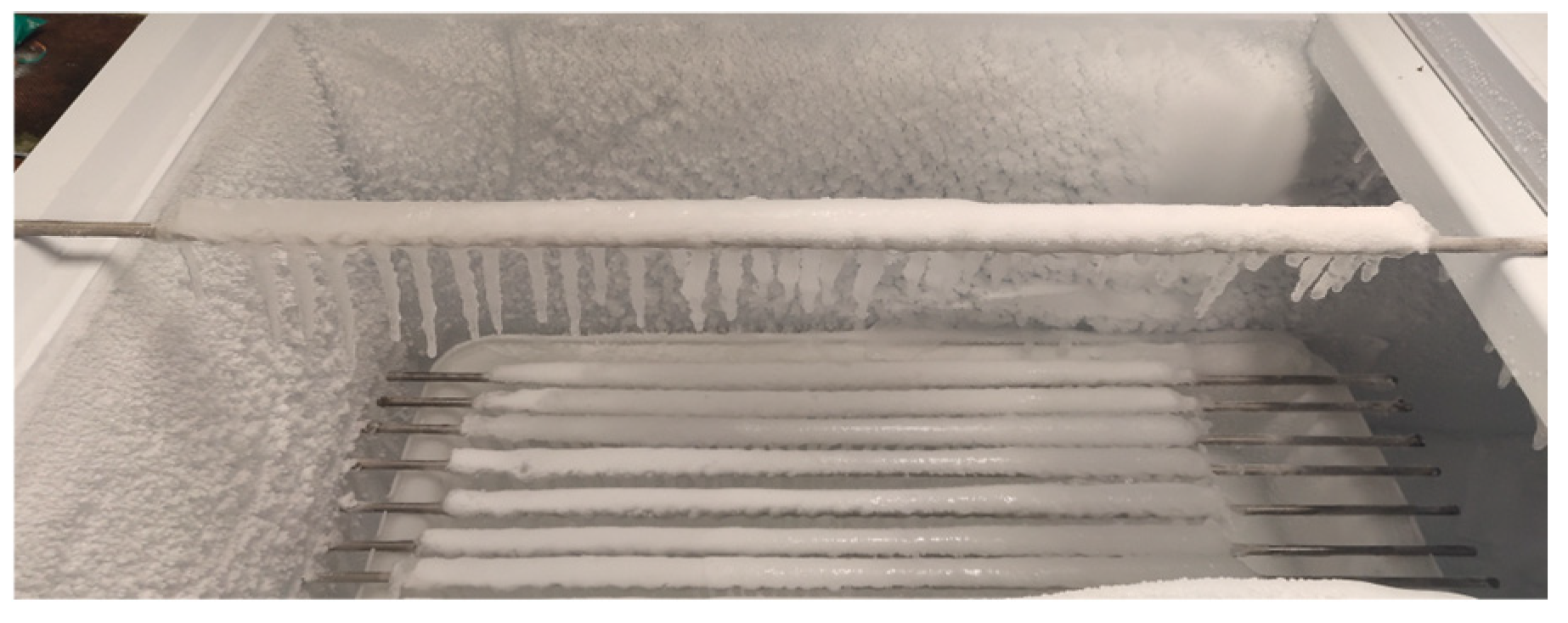
As the core component of the milling-based deicing robot, the deicing milling cutter is commonly designed in a straight-plate configuration [13], as shown in Figure 1. While this design is simple, it relies on the right-angle edges at the notched areas (with a rake angle of 90°) to scrape off the ice during operation. This approach significantly increases cutting resistance. When the cutting resistance becomes excessive, it directly impacts the robot body, resulting in a heavier load on the locomotion mechanism. This leads to vibrations along the transmission line, severely affecting the robot’s stability and the efficiency and safety of the deicing process.
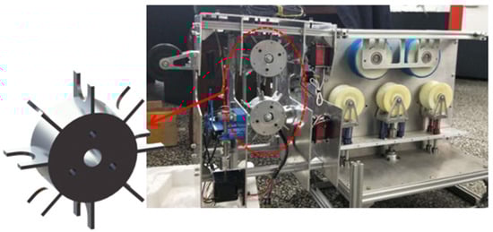
Figure 1.
Milling-type deicing mechanism and deicing milling cutter.
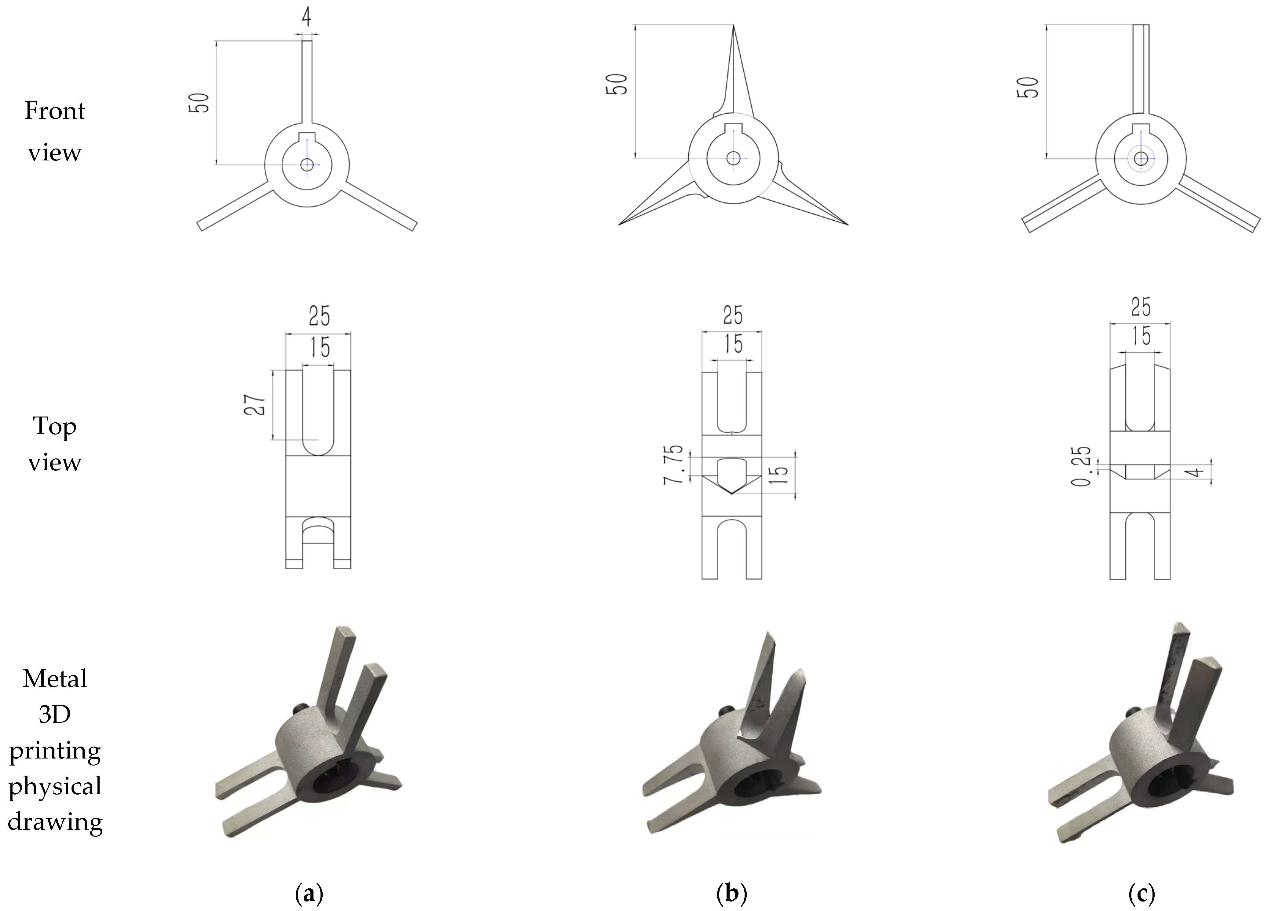
The cutting principle suggests that reducing the rake angle of the tool enhances its sharpness, decreases the deformation of the cutting layer, and reduces the frictional resistance of the chip, thus lowering cutting forces and temperatures. However, an excessively small rake angle may lead to deformation of the tool surface during cutting [23]. Based on this understanding, this study improves upon the traditional straight-plate deicing milling cutter (with a 90° rake angle) by reducing the rake angle, resulting in the development of two new cutter designs: the straight-cut milling cutter (with a 53° rake angle) and the oblique-cut milling cutter (with a rake angle varying from 60° at the base to 90° at the tip). The dimensions of the three milling cutters are shown in Figure 2 and fabricated using metal 3D printing. For the 10 kV distribution network lines (JKLYJ type), the conductor has a cross-sectional area of 50 mm2, is covered with an insulating sheath, and has a total diameter of 11.4 mm [24]. The deicing thickness of the milling cutter is set to 10 mm by the medium-ice-zone standard. Three deicing cutters have a width of 25 mm, a milling cutter blade diameter of 100 mm, and a thickness of 4 mm. A U-shaped cut of 15 mm is made at the blade’s center to allow the cutter to pass through the wire. The center of the cutter has a blind hole and key slot, which can be connected to the motor shaft. During high-speed operation, the U-shaped cutter design cleverly avoids direct contact with the wire, effectively preventing damage to the wire. Furthermore, the bottom structure of the U-shaped notch matches the wire’s shape, ensuring the maximization of the milling area.
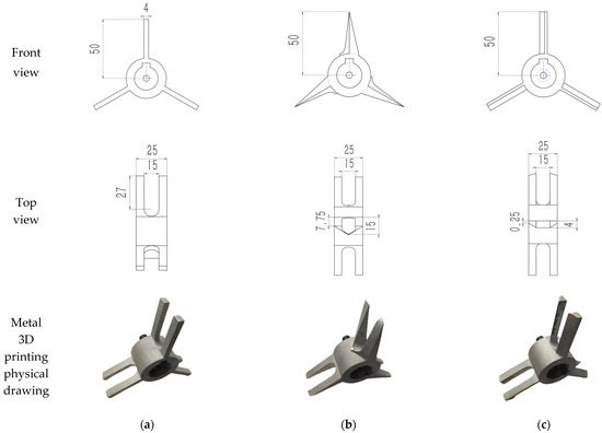
Figure 2.
Dimensions and drawings of three kinds of deicing milling cutters. (a) Dimensions and drawings of straight-plate deicing milling cutter; (b) dimensions and drawings of oblique deicing milling cutter; (c) dimensions and drawings of straight-cut deicing milling cutter.
3. Numerical Simulation of Cutting Forces in Deicing Milling Cutter
To comprehensively obtain cutting force data under various cutting conditions, finite element simulation software is used to model the deicing process of three simplified milling cutter designs. The cutting forces are calculated and compared under equivalent cutting conditions, focusing on the influence of cutter face geometry, feed rate, and milling speed on the cutting forces.
3.1. Fundamentals of Dynamic Finite Element Analysis
This study employs a dynamic finite element method to numerically simulate the interaction between the ice layer and the deicing milling cutter. By discretizing the object into small elements, the dynamic changes of each element are computed and analyzed, thereby determining the overall structural dynamic response of the model.
According to Newton’s second law, the motion of the structural finite element is typically solved by the following equation [25]:
where [M], [C], and [K] are the mass, damping, and stiffness matrices of the structure, respectively; , , and , respectively, represent the acceleration, velocity, and displacement vectors of the unit node; F(t) is the total external force vector of a cell node. The central difference display integral method is used to display and solve Equation (1), and the acceleration vector of the element node can be obtained as follows:
where P(tn) is the external force vector, Fint(tn) is the internal force vector. The expression of the velocity vector and displacement vector for the element node is:
3.2. The Constitutive Equation of the Structure
Assuming that the ice-covering materials are all isotropic, the calculation efficiency and convergence can be improved, and its constitutive equation is as follows [26]:
where λ and μ are Lamay’s elastic coefficients, which can be expressed by the elastic coefficient E and Poisson’s ratio υ:
3.3. Fracture Model of Ice Accretion
During the deicing process, the deicing milling cutter can be simplified as an infinitely large plate with a central horizontal crack, subjected to shear stress parallel to the crack plane, leading to Mode Ⅱ crack propagation. According to the theory of elastic fracture mechanics, the stress field at the crack tip for a Mode Ⅱ crack is expressed in polar coordinates as follows [25,27]:
where KII is the stress intensity factor; r is the polar radius of the intensity factor control region in the crack tip region; θ is the azimuth angle, with the crack tip as the center of the circle.
The fracture energy criterion in the tensile softening model is used to simulate the ice-covered slip open-type-Ⅱ crack fracture, that is, the maximum displacement umaxck of the element failure is set. When the calculated and analyzed maximum displacement umaxck is greater than the model element displacement unck, the element stress is assigned to 0, the element is deleted, and the unit model fracture is judged.
3.4. Model Building and Parameter Setting
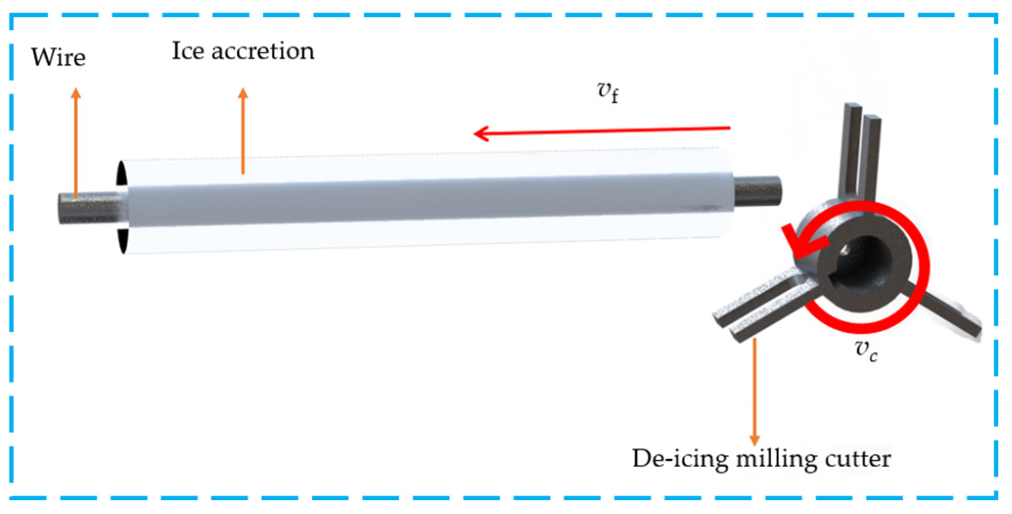
As shown in Figure 3, the wire model is simplified to a cylinder with a length of 240 mm and a diameter of 11.4 mm. The ice accretion model is simplified to a tubular shape with a length of 200 mm wrapped around the wire. The outer diameter of the ice layer is 31.4 mm (with a conductor diameter of 11.4 mm and an ice thickness of 10 mm), while the inner diameter matches the conductor diameter.
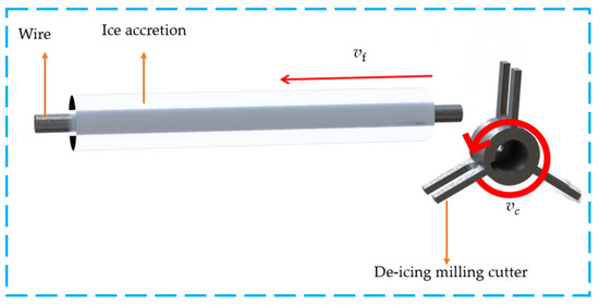
Figure 3.
Schematic diagram of deicing model.
Icing on distribution lines can be classified into five primary types based on environmental conditions such as temperature, humidity, and wind speed; glaze ice, rime ice, wet snow; and mixed forms of glaze and rime ice [28]. Among these, glaze ice poses the most severe threat to distribution lines due to its exceptional strength, high density, and strong adhesion. It is also the most challenging type of ice to remove, making studies on the cutting forces required for glaze ice particularly representative. In light of this, this study’s experimental design of the deicing milling cutter targets glazes as the ice accretion, whose mechanical properties vary with environmental conditions. Relevant material parameters for ice accretion and other materials are listed in Table 1 [29,30,31].

Table 1.
Material parameter table.
Friction exists between the ice accretion, wire, and milling cutter. The contact friction model follows Coulomb’s friction law, with a friction coefficient of 0.5 between the ice accretion and the wire and a coefficient of 0.3 between the ice accretion and the milling cutter. The expression for the frictional force is given by:
where τf is the friction force; μ is the friction coefficient; p is positive pressure.
To ensure the accuracy of the cutting force curves in simulations, a preliminary network sensitivity analysis is conducted. Balancing computational efficiency with precision, the mesh size of the fracture region in the icing model is refined to 0.26 mm.
Experimental studies on deicing reveal that excessively high feed rates or overly low milling speeds could lead to abnormally increased cutting depths, potentially causing the milling cutter to jam during the deicing process. Conversely, overly slow feed rates significantly reduce operational efficiency, rendering the approach unsuitable for practical applications. On the other hand, excessively high milling speeds result in excessively intense cutting forces, introducing safety risks to the deicing operation. Therefore, the selected feed rates for the milling cutter vf are 100 mm/s, 200 mm/s, and 300 mm/s, while the milling speeds n are set to 200 r/min, 400 r/min, 600 r/min, 800 r/min, 1000 r/min, and 1200 r/min.
In the simulation process, the cutting forces for the three milling cutter designs are simulated under different feed and milling speeds. The cutting forces generated by the deicing milling cutter primarily include the axial component of the force fn along the feeding direction of the wire and the vertical tangential component fc. The simulation results are presented in Table 2.
Table 2.
Simulation results of three types of deicing milling cutters under different milling conditions (in N).
4. Deicing Experiment Design of Deicing Milling Cutter
4.1. Artificial Ice Covering
To replicate the formation mechanism of glaze ice on conductors under natural conditions, a custom-built spraying system and fan are placed inside a specialized freezer to simulate a natural icing environment [32]. The freezer allows precise temperature control and stabilization within the range of −40 °C to +10 °C. Ice water at 0 °C to +2 °C is atomized and continuously sprayed within the freezer, maintaining an ambient temperature of −6 °C, which is optimal for glaze ice formation, with a wind speed of 5 m/s. Humidity measurements using a hygrometer inside the freezer confirm that the relative humidity remains within the range of 80–90%. The sealed environment of the freezer ensures the stability of all icing parameters throughout the experiment.
To eliminate potential interference from the wire’s plasticity in cutting force measurements, aluminum rods of the same diameter are used as substitutes for the wire. The aluminum rods, 1 meter in length, are placed inside the freezer, where the ice layer gradually grows. Every half hour, the diameter of the ice-covered wire is measured using a vernier caliper. After approximately six hours of spraying, the diameter of the ice-covered wire reaches the experimental requirement of 31.4 mm (the conductor has a diameter of 11.4 mm with an ice layer thickness of 10 mm, which corresponds to the warning threshold for icing in regions managed by the state grid; research findings on icing at this thickness are therefore more broadly representative). As shown in Figure 4, the upper end of the ice-covered wire forms a semi-cylindrical glaze layer, while the lower end develops an ice ridge approximately 8 cm in length.
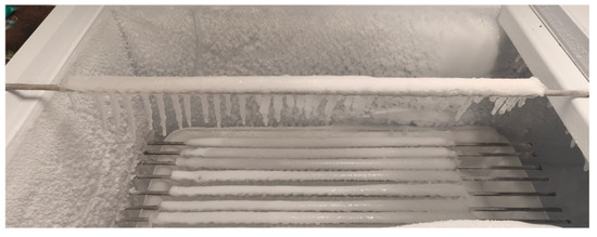
Figure 4.
Ice conductor.
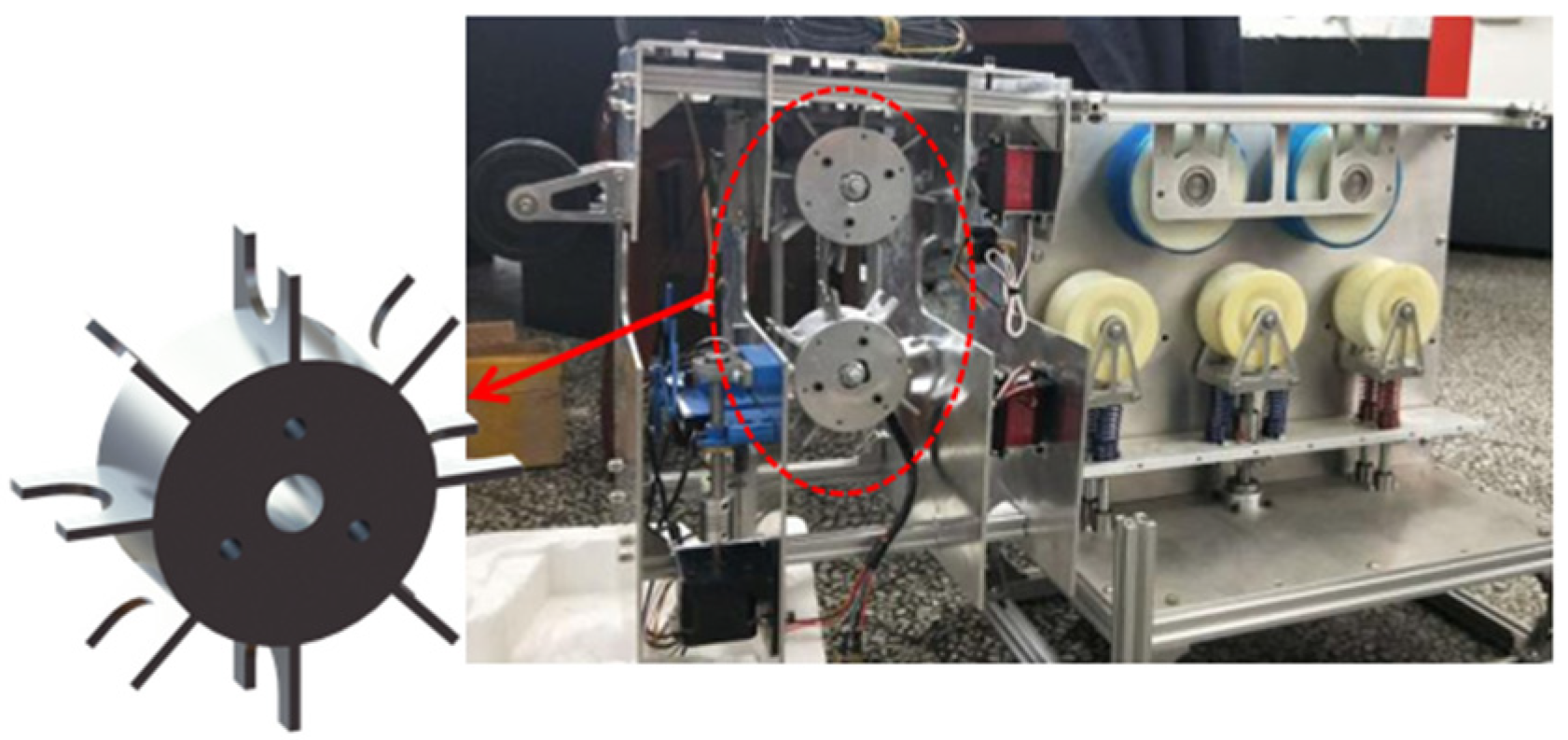
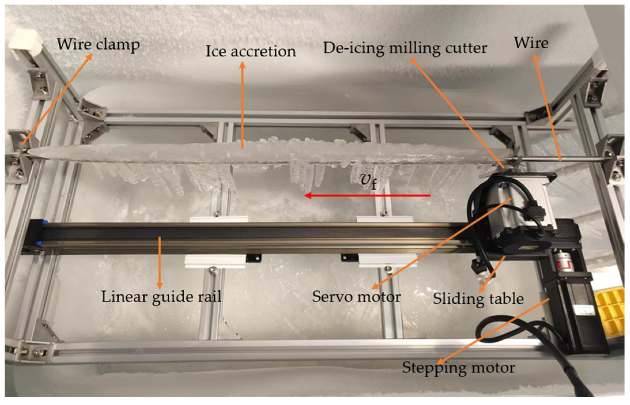
4.2. Deicing Experiment Platform
To simplify the experimental process and minimize the influence of non-experimental factors on the results, the deicing platform employs a linear guide controlled by a stepper motor and a servo motor to simulate the robot’s walking and deicing motions. The servo motor’s rated speed is 3000 r/min, with a rated torque of 2.4 Nm. The stepper motor-controlled linear guide can achieve a maximum feeding speed of 400 mm/s, meeting the experimental requirements.
As shown in Figure 5, the servo motor shaft is connected to the deicing milling cutter and mounted on the linear guide carriage to facilitate its rotation and feeding motion. The ice-covered metal rod is securely fixed at both ends of the profile frame, ensuring stability during the experiment.
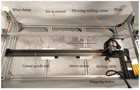
Figure 5.
Deicing experiment platform.
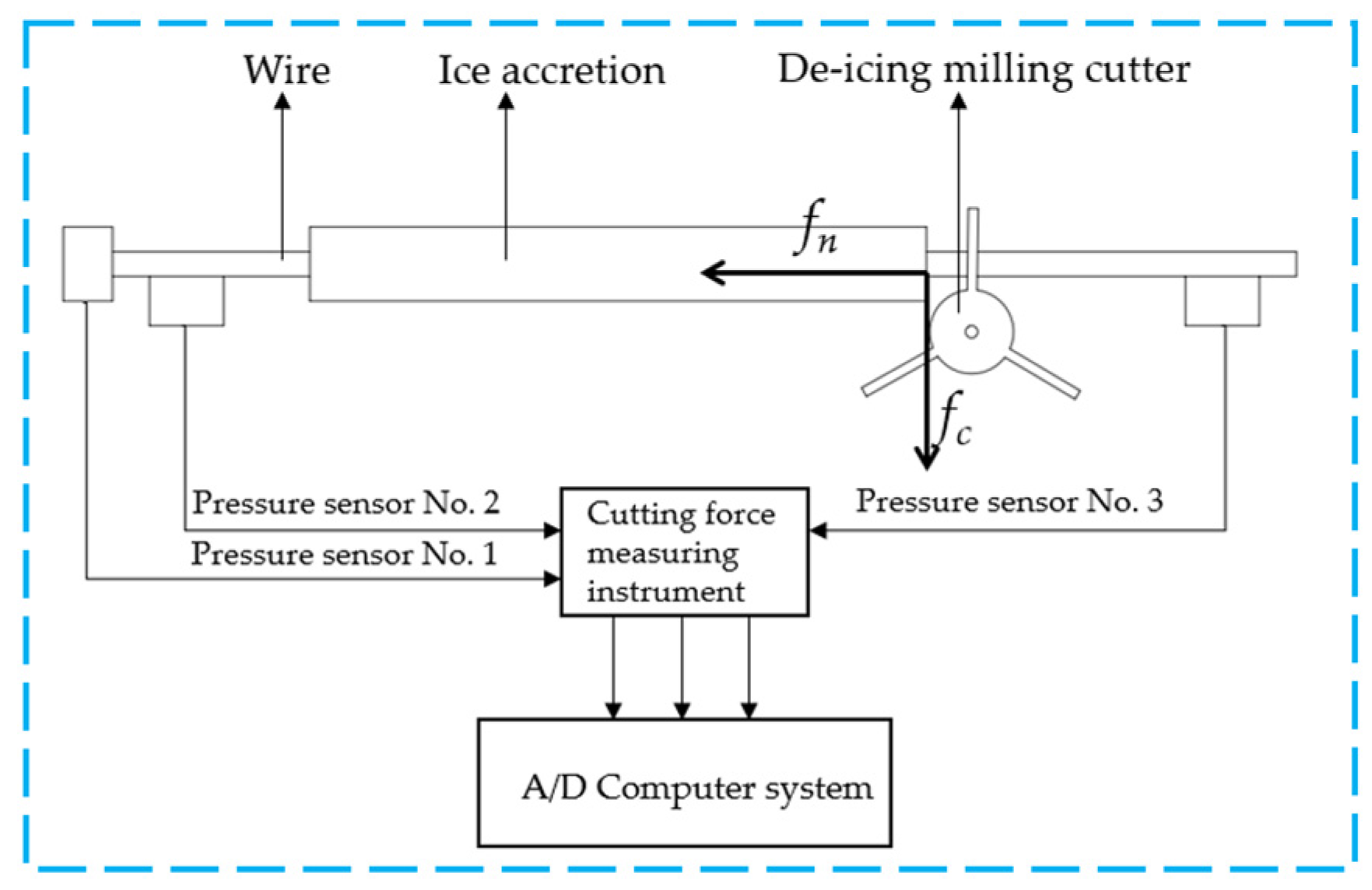
To accurately measure the cutting forces generated by the deicing milling cutter during the deicing experiment, a cutting force measurement system is integrated into the deicing experimental platform, as shown in Figure 6. During the milling and deicing process, the axial component of the cutting force fn and the tangential component fc are transmitted through the ice accretion to the metal rod. Pressure sensor 1 is connected to one end of the metal rod to output the axial force curve experienced by the rod. Pressure sensors 2 and 3 are placed beneath both ends of the metal rod to output the tangential force curves experienced by the rod.
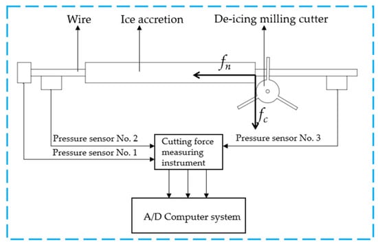
Figure 6.
Cutting force measurement system.
During the measurement of cutting forces, the stochastic nature of ice fracture can introduce significant deviations in some results. To mitigate the impact of this randomness, this study increases the number of cutting trials and selects the maximum value from each measurement sequence as the final result.
5. Analysis of Simulation Results and Experimental Verification of Deicing Milling Cutter
The cutting forces during the deicing process can be determined by analyzing the XY curves of the forces acting on the deicing milling cutter’s node set. Due to the unique structure of the straight-cut and inclined-cut milling cutters, radial forces in the horizontal direction are generated. However, these forces are relatively small and can be ignored.
During the deicing operation, the axial component of the cutting force generates a counteracting reaction force in the forward direction of the deicing robot. Excessive axial force increases the load on the robot’s walking mechanism. The tangential component of the cutting force generates an upward reactive force on the deicing robot. Moreover, due to the discontinuous nature of the cutting process, intermittently excessive tangential forces can induce severe vibrations in both the robot and the conductor. Therefore, it is crucial to compare the cutting force data and select the optimal values to ensure both deicing and walking stability.
5.1. Effects of Milling Cutter Face Shape and Milling Speed on Cutting Forces
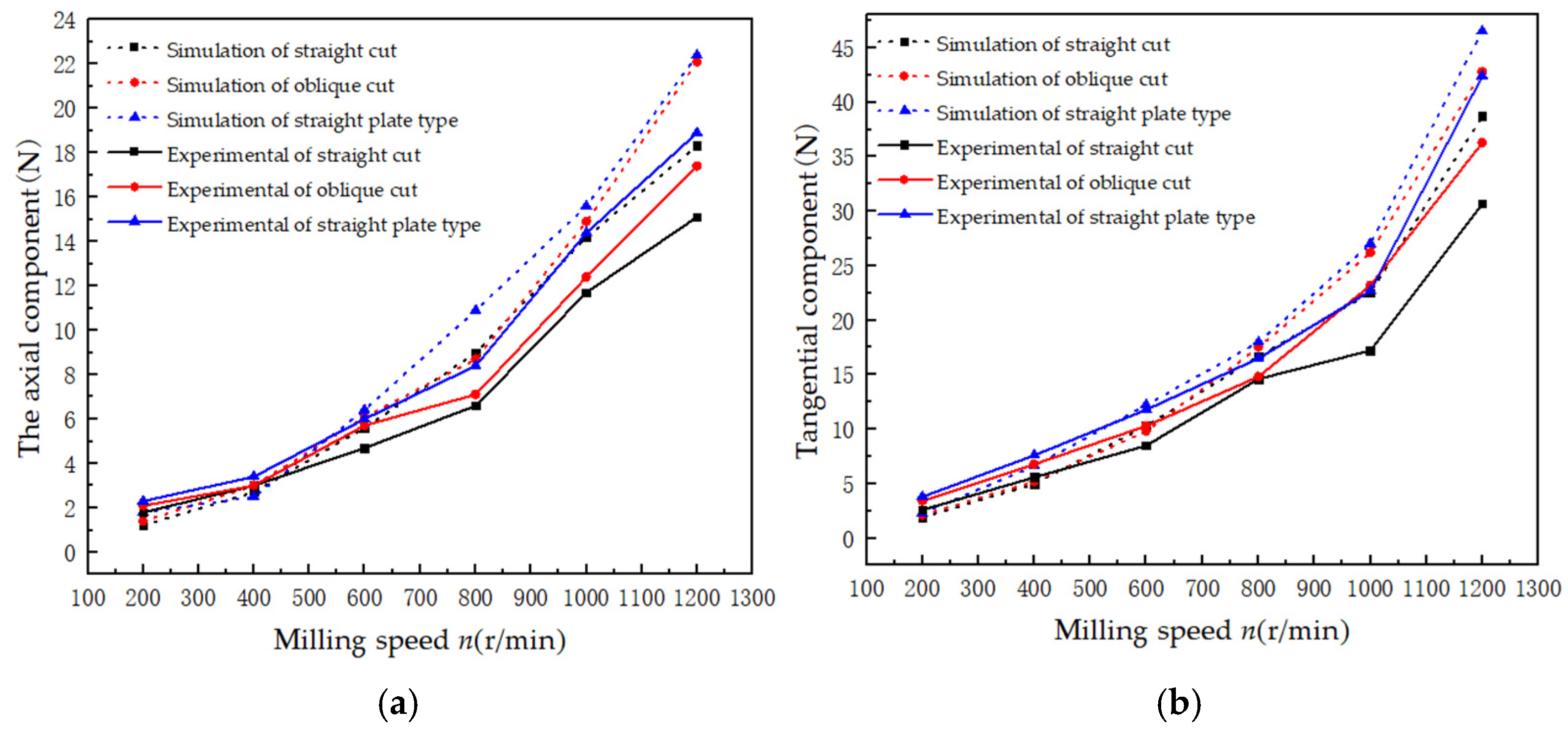
Keeping the feed speed vf constant at 200 mm/s while varying the milling speed n, simulations of the milling process are conducted for the three deicing milling cutters, followed by experimental validation. The axial and tangential components of the cutting force for each cutter are measured, and their variations with milling speed are shown in Figure 7.
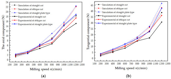
Figure 7.
Effect of milling speed on cutting force. (a) Variation diagram of axial force with milling speed; (b) variation diagram of tangential force with milling speed.
The experimental results generally align with the trends observed in the simulation results, although minor discrepancies exist when comparing individual data points. These differences can be attributed to several factors: insufficient rigidity of the experimental platform, variations between the actual material properties of ice and their theoretical counterparts, and the generation of substantial ice fragments during the deicing process. The latter alters friction within the experimental platform, thereby influencing the accuracy of cutting force measurements. Overall, the experimental results validate the accuracy of the simulation outcomes.
Under the same milling conditions, the downward tangential force fc is greater than the axial force fn. Generally, the cutting force magnitudes for the three deicing milling cutters follow the following order: straight-plate > inclined-cut > straight-cut. Compared with the straight-plate cutter, the straight-cut milling cutter can reduce the cutting force by 16% to 33%.
The reasons for this phenomenon are as follows:
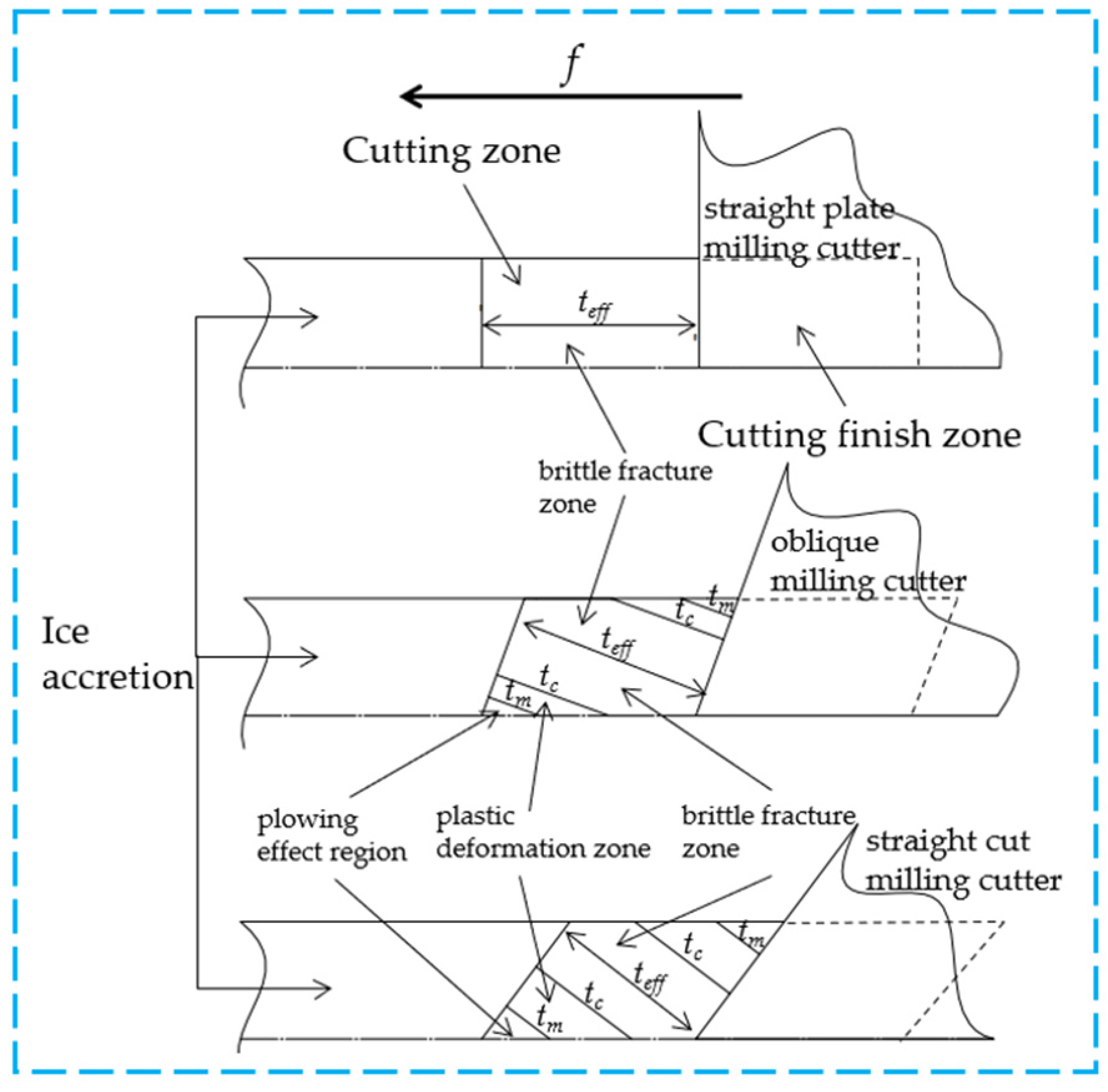
Since the ice accretion is a brittle material, the cutting zone in contact with the cutter during the milling process can be divided into three subregions: the ploughing effect region, the plastic deformation region, and the brittle fracture region [33], as shown in Figure 8. The cutting force FD generated in the first two regions results from ductile material removal, while the cutting force FB in the brittle fracture region is caused by brittle fracture. The cutting force generated in the brittle fracture region is the largest, followed by the plastic deformation region. In contrast, the ploughing effect region generates the least cutting force, where the material deforms without producing chips. Therefore, the cutting force caused by brittle fracture dominates the total cutting force.
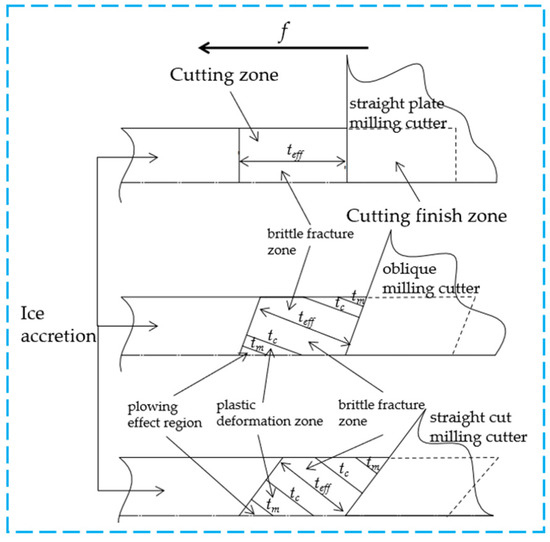
Figure 8.
Regional distribution map of ice-coated chips for three kinds of deicing milling cutter.
The three subregions are divided by the icing material’s chip thickness. The icing material chip has a minimum chip thickness tm and a critical chip thickness tc. When the effective chip thickness teff is less than the minimum chip thickness tm, the cutting region is the ploughing effect region. The cutting zone of teff between tm and tc is a plastic deformation zone. The cutting zone with teff greater than tc is a brittle fracture zone.
An analysis of the milling diagrams for the three deicing milling cutters, particularly focusing on the morphology of the cutting completion zone, reveals that the cutter face’s rake angle influences the chip shape. Theoretically, under identical milling conditions, the straight-plate cutter generates the thickest chips, while the straight-cut cutter, with a smaller rake angle, produces the thinnest chips. Under the same milling conditions, the chip sizes produced by the three deicing milling cutters are equivalent. However, the straight-cut cutter exhibits the smallest proportion of brittle fracture zone and the largest proportion of ductile mode, whereas the straight-plate cutter’s chips are characterized by the largest proportion of brittle fracture and the smallest proportion of ductile mode. The chips the inclined-cut cutter produces exhibit characteristics between the two.
Moreover, as shown in Figure 7, with the increase in milling speed n, the cutting forces for all three deicing milling cutters exhibit an upward trend. The axial force fn and tangential force fc follow a functional relationship with milling speed, respectively, as shown below:
The cause of this phenomenon is as follows:
During the deicing process, as the milling speed increases, the proportion of the brittle fracture region in the cutting zones grows across all three cutters. Specifically, under higher milling speeds, the cutting force induced by a brittle fracture in the ice-cutting zone increases significantly compared with lower milling speeds. Although the cutting force caused by ductile removal slightly decreases at higher milling speeds, this reduction is insufficient to offset the increased cutting force caused by brittle fracture. Therefore, comprehensive analysis indicates that the total cutting force at higher milling speeds tends to increase relative to lower milling speeds.
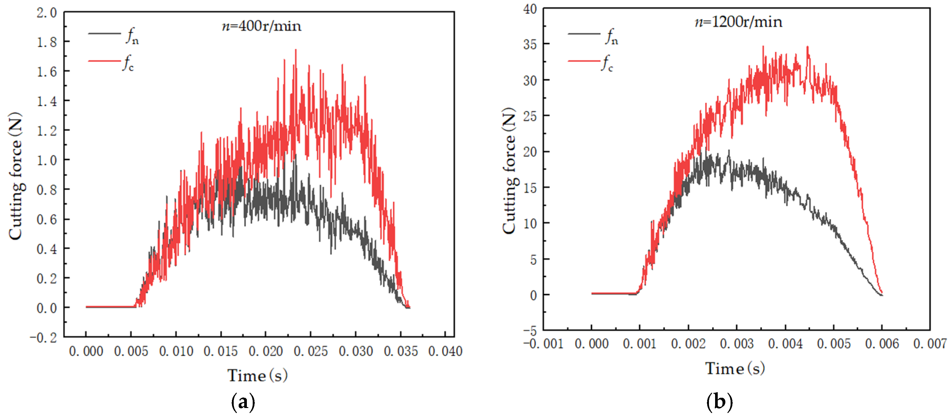
An increase in milling speed for the same deicing milling cutter leads to more pronounced fluctuations in the cutting force. For instance, for the inclined-cut deicing milling cutter at a feed speed of vf = 100 mm/s, when the milling speed is set to 400 r/min and 1200 r/min, the corresponding cutting force curves from the simulation are shown in Figure 9. In the former case, the maximum fluctuation in the tangential force is approximately 20%, while it is about 26% in the latter case. This demonstrates that, with an increase in cutting force corresponding to higher milling speeds, the fluctuation of cutting force at higher speeds is significantly greater than at lower speeds.

Figure 9.
The fluctuation of cutting force at two milling speeds. (a) Simulation cutting force when n = 400 r/min; (b) simulation cutting force when n = 1200 r/min.
During the milling of brittle materials, cracks typically originate in the brittle fracture zone, accompanied by fluctuations in cutting force. As observed from the previous analysis, when the deicing milling cutter’s milling speed increases, the proportion of the brittle fracture region in the ice-cutting zone increases. This results in a higher number of cracks within the cutting zone, thereby intensifying the fluctuations in cutting force, leading to increased instability in the cutting force and subsequently affecting its magnitude.
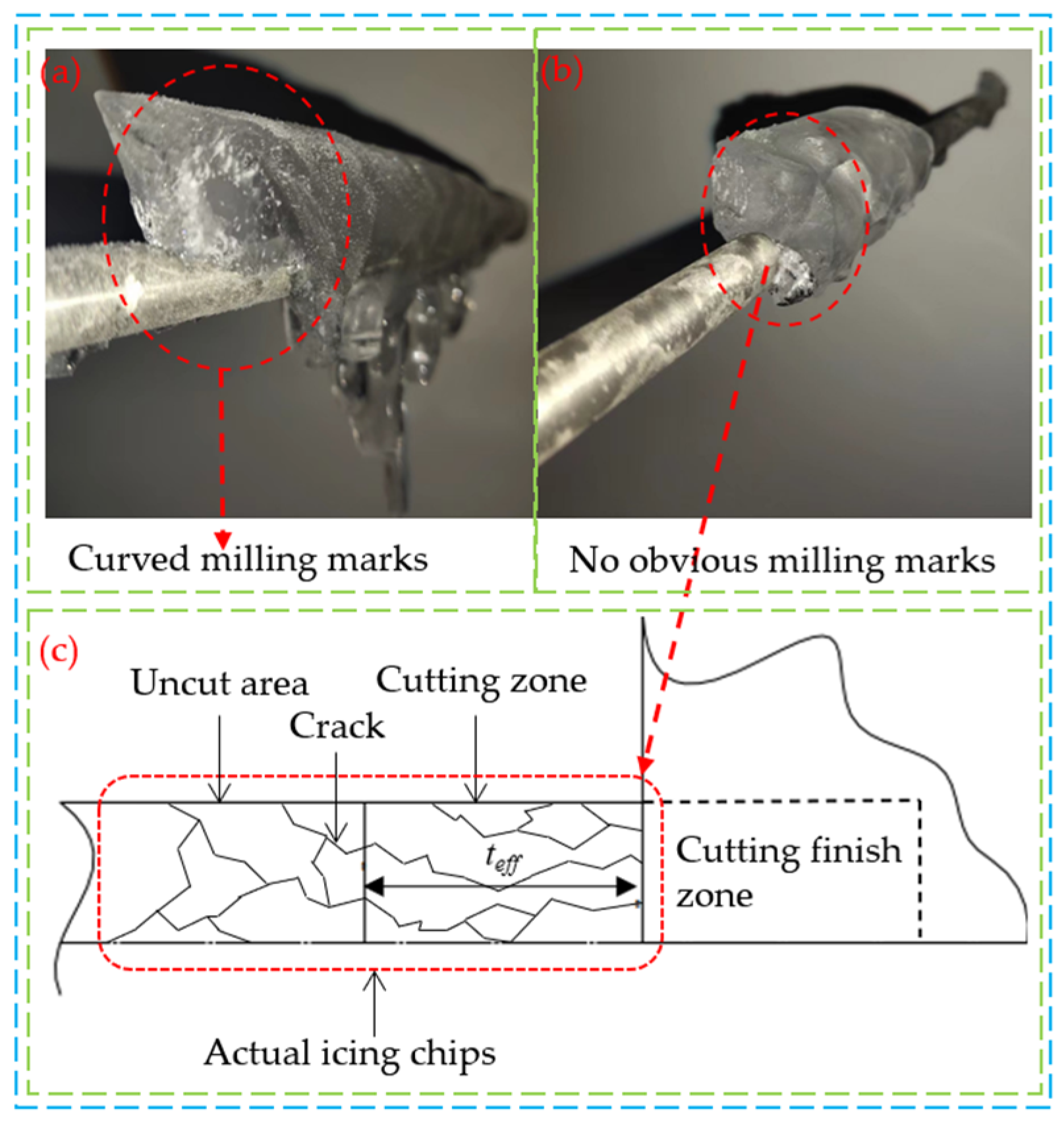
Figure 10a and Figure 10b, respectively, show cross-sectional views of ice at a particular moment when the milling speed is 200 r/min. The cross-section in Figure 10a exhibits distinct arc-shaped milling marks, while the cross-section in Figure 10b lacks regular milling patterns. This phenomenon can be attributed to the increase in the proportion of the brittle fracture zone in the cutting area, as shown in Figure 10c. As the proportion of the brittle fracture zone increases, the number of cracks also increases. These cracks extend across the cutting area and into the uncut region, increasing the cut material’s volume. Due to the randomness of crack growth, the chips take on an irregular shape. Therefore, compared with Figure 10a, under the same milling conditions, the increased chip volume in Figure 10b indirectly leads to a larger proportion of brittle fracture and ductile removal zones, requiring a greater cutting force to complete the milling process.

Figure 10.
Two sections after ice milling. (a) Curved milling marks; (b) No obvious milling marks; (c) Schematic diagram of chips without obvious milling marks.
In the deicing experiments, when the milling speed of the deicing cutter is in the range of 200–400 r/min, approximately 60% of the ice removed using the straight-cut milling cutter has a cross-section characterized by arc-shaped milling traces, as shown in Figure 10a. In contrast, the proportion of this characteristic cross-section for the inclined-cut and flat-cut milling cutters is approximately 30% and 25%, respectively, when processing the same ice layer. As the milling speed increases, the proportion of arc-shaped milling traces decreases dramatically for all three types of deicing milling cutters. In most cases, this is replaced by irregularly shaped large-volume ice chips produced from irregular milling sections.
Based on the comparison of the aforementioned simulation and experimental results, the straight-cut type exhibits the smallest cutting force among the three deicing milling cutters, reducing it by 16% to 33% compared with the traditional straight-plate milling cutter. When the deicing milling cutter’s cutting speed ranges from 200 to 400 r/min, the cutting force remains relatively low and stable.
5.2. Effect of Feed Speed on Cutting Force
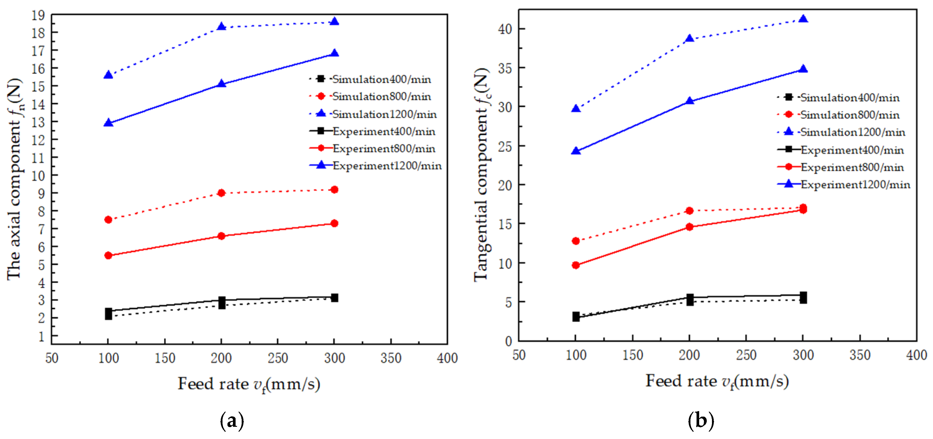
This study selected three milling speeds for the straight-cut deicing milling cutter, and simulations and experimental validations were performed by varying only the feed speed vf. Figure 11 shows the axial and tangential components of the cutting force for the straight-cut deicing milling cutter at three milling speeds as a function of feed speed vf. The cutting force increases with the feed speed, and the impact of feed speed on the cutting force is more pronounced at higher milling speeds.
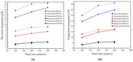
Figure 11.
Effect of feed speed on cutting force. (a) Variation diagram of axial force with feed rate; (b) variation diagram of tangential force with feed rate.
The reasons for this phenomenon are as follows:
As the feed speed increases, the cutting depth of the deicing milling cutter also increases over the same period. This leads to an increased proportion of the brittle fracture region, where the brittle fracture area at higher feed speeds is larger than at lower feed speeds, while the ductile mode region at higher feed speeds is slightly smaller than at lower feed speeds. As a result, at higher feed speeds, the cutting force induced by a brittle fracture in the deicing cutting zone is greater than at lower feed speeds. In comparison, the cutting force generated by ductile removal is slightly smaller than at lower feed speeds, leading to a total cutting force at higher feed speeds greater than at lower feed speeds.
At a milling speed of 400 r/min, the effect of feed speed on the cutting force is relatively small, with the cutting force remaining nearly constant. Based on this observation, larger feed speeds should be prioritized at lower milling speeds to enhance deicing efficiency. Therefore, based on the above analysis, a feed speed of 300 mm/s was selected for this study.
6. Conclusions
This study explored the influence of the tool surface shape, milling speed, and feed speed of the milling-type deicing robot’s deicing cutter on cutting force based on both simulation analysis and experimental validation. The following conclusions were drawn:
- (1)
- Influence of tool surface angle: Under identical milling conditions, among the three types of deicing cutters, the straight-cut deicing milling cutter exhibited the lowest cutting force. Compared with the traditional flat-type cutter, it reduced the cutting force by 16% to 33%.
- (2)
- Effect of milling speed: The cutting force increased with milling speed under the same milling conditions. Moreover, a higher milling speed intensified cutting force fluctuations. Through deicing experiments, it was found that the optimal milling speed range for an ice thickness of 10 mm was between 200 and 400 r/min. Within this range, the cutting force remained relatively low and stable, and the vibrations during deicing operations were effectively controlled, significantly improving the overall stability of the deicing process.
- (3)
- Effect of feed speed: The cutting force increased with increasing feed speed under the same milling conditions. However, at lower milling speeds, the impact of feed speed on cutting force was relatively small. The increase in feed speed, on the other hand, significantly enhanced deicing efficiency. Therefore, considering all factors, the optimal feed speed was selected as 300 mm/s.
Author Contributions
Conceptualization, J.Z. and C.T.; methodology, J.Z.; investigation, M.Z. and W.C.; data curation, H.Y. and D.W.; writing—original draft preparation, J.Z.; writing—review and editing, G.H. and C.T. All authors have read and agreed to the published version of the manuscript.
Funding
This study was funded by the Fundamental Research Funds for Central Universities, grant number SWU120062.
Data Availability Statement
The data presented in this study are available on request from the corresponding author.
Conflicts of Interest
Author Maolin Zhu was employed by the State Grid Zhejiang Electric Power Company Hangzhou Yuhang District Power Supply Company. Author Wenchao Chen was employed by the State Grid Zhejiang Electric Power Company Hangzhou Power Supply Company. Authors Hongchun Yang and Donghong Wei were employed by the Yongchuan Power Supply Branch Company of State Grid Chongqing Electric Power Company. The remaining authors declare that the research was conducted in the absence of any commercial or financial relationships that could be construed as a potential conflict of interest.
References
- Hu, Q.; Yu, H.J.; Li, Y.; Shu, L.; Jiang, X.; Liang, J. Numerical and experimental study of accreted ice on bundle conductor. High Volt. Eng. 2017, 43, 900–908. [Google Scholar]
- Farzaneh, M. Ice accretions on high voltage conductors and insulators and related phenomena. Philos. Trans. R. Soc. Lond. Ser. A Math. Phys. Eng. Sci. 2000, 358, 2971–3005. [Google Scholar] [CrossRef]
- Farzaneh, M. Atmospheric Icing of Power Networks; Springer: Berlin/Heidelberg, Germany, 2008. [Google Scholar]
- Wang, S.H. Analysis of typical ice accidents of transmission lines and preventing techniques. High Volt. Appar. 2010, 46, 85–89. [Google Scholar]
- Chao, Y.F.; Yue, Y.S.; Wang, C. De-icing techniques for ice-covered transmission lines: A review. High Volt. Appar. 2016, 52, 1–9. [Google Scholar]
- Zhang, Z.; Zhang, H.; Yue, S.; Zeng, W. A Review of icing and anti-icing technology for transmission lines. Energies 2023, 16, 601. [Google Scholar] [CrossRef]
- Wang, Z.J. Recent progress on ultrasonic de-icing technique used for wind power generation, high-voltage transmission line and aircraft. Energy Build. 2017, 140, 42–49. [Google Scholar] [CrossRef]
- Montambault, S.; Pouliot, N. The HQ Line-Rover: Contributing to innovation in transmission line maintenance. In Proceeding of the 2003 IEEE 10th International Conference on Transmission and Distribution Construction, Operation and Live-Line Maintenance, Orlando, FL, USA, 6–10 April 2003; pp. 33–40. [Google Scholar]
- Cao, L.; Guo, R.; Zhang, F. Mechanical structure research of deicing robot for high voltage. Mach. Des. Manuf. 2013, 266, 147–149. [Google Scholar]
- Wei, S.N.; Wang, Y.N.; Yin, F.; Yang, Y. Design of de-icing mechanism of de-icing robot for high voltage power transmission line. China Mech. Eng. 2012, 23, 771–776. [Google Scholar]
- Xian, H.X.; Qiao, G.; Wang, L.L.; Chen, T.C.; Wu, H.Y. Structural design and simulation analysis of intelligent de-icing robots for high voltage transmission lines based on TRIZ theory. J. Mach. Des. 2023, 1–8. [Google Scholar]
- Yu, F.H. Design and Analysis of the Anti-Icing and Deicing Robot System Fortransmission Lines. Master’s Thesis, Southwest Jiaotong University, Chengdu, China, 2022. [Google Scholar]
- Yi, Q.Z. Research on Active Anti-Icing/De-Icing Robot Control System for Power Transmission Lines. Master’s Thesis, Southwest Jiaotong University, Chengdu, China, 2021. [Google Scholar]
- Cao, W.M. Research on Visual Control Methods for High Voltage Transmission Line Deicing Robot. Ph.D. Thesis, Hunan University, Hunan, China, 2014. [Google Scholar]
- Liu, J.W.; Huang, Z.Q.; Liao, Y.J.; Ning, L.; ET Center. Design of robot on anti-icing and de-icing of high voltage wire. Mach. Tool Hydraul. 2014, 42, 42–45. [Google Scholar]
- Yang, H.; Jiang, F.; Wu, X.; Zhao, G.; Shi, X.; Liu, G.; Wang, M. Optimizing the cutting-edge geometry of micro drill based on the entropy weight method. Int. J. Adv. Manuf. Technol. 2023, 125, 2673–2689. [Google Scholar] [CrossRef]
- Zhang, W.; Hua, B.; Zhang, L.; Si, B. Modeling and simulation of surface topography in secondary milling with ellipsoid end milling cutter. Int. J. Interact Des. Manuf. 2024, 18, 5043–5056. [Google Scholar] [CrossRef]
- Maity, K.; Pradhan, S. Investigation of FEM simulation of machining of titanium alloy using microgroove cutting insert. Silicon 2018, 10, 1949–1959. [Google Scholar] [CrossRef]
- Wu, Z.; Buck, D.; Zhang, F.; Yu, Y.; Guo, X.; Cao, P.; Zhu, Z. Finite element method and its application to cutting processes of stone–plastic composite. Int. J. Adv. Manuf. Technol. 2023, 129, 4491–4508. [Google Scholar] [CrossRef]
- Wang, L.; Yue, C.; Liu, X.; Li, M.; Xu, Y.; Liang, S.Y. Conventional and micro scale finite element modeling for metal cutting process: A review. Chin. J. Aeronaut. 2024, 37, 199–232. [Google Scholar] [CrossRef]
- Oguzhan, D.; Muhammed, O.; Gokhan, B. Optimization of cutting parameters in manufacturing of polymeric materials for flexible two-phase thermal management systems. Mater. Test. 2024, 66, 1700–1719. [Google Scholar]
- Elsheikh, A.H.; Deng, W.; Showaib, E.A. Improving laser cutting quality of polymethylmethacrylate sheet: Experimental investigation and optimization. J. Mater. Res. Technol. 2020, 9, 1325–1339. [Google Scholar] [CrossRef]
- Du, S.M. Fundamentals of Machinery Manufacturing; China Machine Press: Beijing, China, 2022. [Google Scholar]
- GB 51302-2018; Design Standard for Overhead Insulated Distribution Lines. China Electricity Council: Beijing, China, 2018.
- Ma, J.J. Methodology Research on the Numerical Simulation of the Bending Failure of Sea Ice. Master’s Thesis, Tianjin University, Tianjin, China, 2013. [Google Scholar]
- Li, Q.; Ou, Z.C.; Chen, Y.H. Advanced Fracture Mechanics; Science Press: Beijing, China, 2017. [Google Scholar]
- Yang, X.H. Study on Mechanism and Criterion for Brittle/Ductile Fracture and Theory of Crack-Tip Deformation. Ph.D. Thesis, Dalian University of Technology, Dalian, China, 2005. [Google Scholar]
- Lou, W.J.; Bai, H. Study on wind load increase coefficient of conductors with various ice coating shapes. High Volt. Appar. 2022, 58, 8–15. [Google Scholar]
- Jiang, X.L.; Shu, L.H.; Sun, C.X. Pollution and Ice Insulation in Power System; China Electric Power Press: Beijing, China, 2009. [Google Scholar]
- Gupta, V.; Bergstrom, J.S. A progressive damage model for failure by shear faulting in polycrystalline ice under biaxial compression. Int. J. Plast. 2002, 18, 507–530. [Google Scholar] [CrossRef]
- Dong, W.; Ding, J.; Zhou, Z.X. Experimental study on the ice freezing adhesive characteristics of metal surfaces. J. Aircr. 2014, 51, 719–726. [Google Scholar] [CrossRef]
- Zhang, H.B.; Wu, H.T.; Hu, Q.; Su, L.C.; He, G.H. Influence of dc electric field intensity on conductor glaze icing and its corona loss. High Volt. Appar. 2022, 58, 275–279. [Google Scholar]
- Huang, W.; Yu, D.; Zhang, M.; Cao, Q.; Yao, J. Predictive cutting force model for ductile-regime machining of brittle materials. Int. J. Adv. Des. Manuf. Technol. 2018, 98, 781–790. [Google Scholar] [CrossRef]
Disclaimer/Publisher’s Note: The statements, opinions and data contained in all publications are solely those of the individual author(s) and contributor(s) and not of MDPI and/or the editor(s). MDPI and/or the editor(s) disclaim responsibility for any injury to people or property resulting from any ideas, methods, instructions or products referred to in the content. |
© 2025 by the authors. Licensee MDPI, Basel, Switzerland. This article is an open access article distributed under the terms and conditions of the Creative Commons Attribution (CC BY) license (https://creativecommons.org/licenses/by/4.0/).