Abstract
This study introduces an automated test bench designed to optimize flocculation-thickening processes in the wastewater treatment industry. Addressing current challenges in operational efficiency and cost reduction, the test bench employs Model-Based Systems Engineering (MBSE) principles, leveraging SysML modeling within the CESAM framework. By integrating advanced technologies, including PLC programming and a closed-loop control system, this bench provides precise and efficient testing under varying operational conditions. Economic implications are explored, demonstrating the cost-effectiveness of optimized flocculation processes, which reduce chemical use and operational expenditures while enhancing water clarity and sludge management. The system’s 3D modeling enables detailed simulations, aiding in both research and pedagogical applications. This platform highlights the potential of MBSE in creating scalable, robust solutions that contribute to sustainable water management.
1. Introduction
Water is one of the most vital natural resources on Earth, essential for sustaining human life, agriculture, and industry. However, with urbanization and rapid population growth, the demand for water has surged, resulting in water scarcity in many regions worldwide. Additionally, water quality has deteriorated due to pollution from domestic, industrial, and agricultural activities, as well as improper waste management. Wastewater treatment mitigates these challenges by systematically eliminating contaminants and pollutants from wastewater, thereby ensuring its suitability for safe reuse or environmentally compliant discharge [1,2,3].
Wastewater treatment involves three primary stages: chemical, physical, and biological processes. Physical methods are employed to remove solid particles, while chemical treatments, such as flocculation, utilize specific chemicals like alum or polyacrylamides to eliminate impurities from water, including organic matter, heavy metals, and suspended solids. Biological methods break down organic matter through the action of microorganisms, completing the treatment cycle [4]. In industrial applications, these processes are crucial for various sectors, such as the phosphate industry, where the thickening phase significantly enhances water recovery and sludge concentration [5,6]. This phase relies heavily on the efficiency of flocculation, where flocculants agglomerate particles, accelerating sedimentation and achieving gradual clarification without a distinct interface between solid and liquid phases. The effectiveness of this process is closely linked to the efficiency of the flocculation stage. Flocculants also play a vital role in other industries, including pulp processing, biopharmaceutical downstream operations, and food and fermentation processes. Flocculation and thickening are not only essential for industrial applications but also fundamental to advancing research and education in water treatment technologies. A thorough understanding of these processes enables scientists and engineers to develop innovative, efficient methods for contaminant removal, ultimately contributing to sustainable water management practices and addressing global water challenges [7,8,9,10,11,12].
Systems engineering adopts an interdisciplinary approach, managing the lifecycle of a system from conception to decommissioning. This methodology is supported by a range of standards [13,14,15], such as EIA-632, ISO 12588, and IEEE 1220 [16,17], which provide guidelines for best practices in systems engineering. As systems become more complex, especially in digital and industrial domains, Model-Based Systems Engineering (MBSE) is increasingly being used by industries and governmental bodies to manage this complexity [17]. MBSE uses digital models as the primary means of communication and analysis, offering significant advantages in terms of efficiency, accuracy, and traceability [18,19]. MBSE relies on modeling languages such as the Unified Modeling Language (UML) and Systems Modeling Language (SysML), which help structure and represent complex system behaviors and architectures. Various Model-Based Systems Engineering (MBSE) methodologies have been developed and are extensively documented in scientific literature. Notable examples include the CESAMES Systems Architecting Method, the MBSE Grid, IBM Harmony, and the U.S. Department of Defense Architecture Framework (DoDAF) [20,21,22]. These methodologies offer systematic approaches for organizing and managing system architecture, ensuring that all system elements are effectively aligned and integrated. In the context of this study, the goal is to design and analyze a flocculation-thickening testing apparatus tailored for laboratory applications, leveraging MBSE to effectively manage the complexity associated with the system’s design and operational processes. This test bench will be used for studying and optimizing flocculation and thickening processes, critical for applications in water treatment and other industrial processes. The MBSE grid methodology and the CESAM framework were selected to guide the system’s design, ensuring a comprehensive and structured approach that fulfills all specified requirements. The SysML was selected as the modeling language to represent the system’s functional, behavioral, and structural elements. This language allows for detailed modeling of the system, enabling clear visualization of interactions, flows, and dependencies between different components [20,23].
Delong Cui et al. highlight that as onboard systems in aircraft become more complex, traditional design methods for ground testing equipment are increasingly inadequate. To address these issues, the authors propose using MBSE. They employed SysML, the Rhapsody modeling tool, and the Harmony-SE methodology to improve the design process. By closely integrating requirements, functions, and architecture, MBSE significantly enhances design efficiency, ensures equipment quality, and reduces development costs and risks. This approach offers a robust workflow tailored to meet stakeholder needs in developing aircraft ground testing systems [24]. Oussama Laayati et al. present a study focused on “designing an educational test bench for smart grids and renewable energy systems. The test bench aims to facilitate research and learning for students, laboratory engineers, and researchers by enabling the study of electrical microgrid systems and the testing of advanced control algorithms to improve energy efficiency”. The system’s MBSE framework outlines the requirements and case studies, adhering to the principles of frugal innovation by using low-cost hardware and software (Cameo Systems Modeler 19.0 LTR SP3, Vélizy-Villacoublay, France). This approach provides flexibility, enabling users to add new sources, change software platforms, and interface with other simulators. The system facilitates students’ comprehension of fundamental smart grid concepts, encompassing defect classification, energy optimization, and energy forecasting, as well as the principles of energy production, transmission, and consumption [25]. Hicham et al. discuss the increasing attention electric vehicles have received due to stricter global emission policies. This article presents the initial phase in the design and development of a test bench for the powertrain of an electric vehicle, with the dual objectives of supporting research activities and serving educational purposes. The methodology employed is MBSE, specifically through the CESAM architecture and modeling framework. This methodology enabled the conceptualization and formalization of an operational architecture for the powertrain test bench, serving as a pivotal step in the preliminary design phase of the system [26].
The main objective of this study is to design and implement an automated test bench to optimize flocculation-thickening processes, which are critical in wastewater treatment. The tasks performed include (1) identifying stakeholder requirements, (2) developing a system architecture using MBSE and SysML, (3) designing the mechanical and electrical components of the bench, (4) programming the control system, and (5) evaluating the performance of the bench for various industrial and educational applications.
2. Challenges of Flocculation-Thickening Testing
2.1. Flocculation-Thickening Testing Systems
The efficiency of flocculants in water treatment is influenced by several challenges, including the variability of sedimentation velocity measurement techniques. Methods like visual observation and sludge height measurements lack precision and depend on subjective assessment. Turbidimetry and gravimetric analysis, while more quantitative, are resource-intensive and sensitive to external factors. Jar Test is a classic and widely adopted method for evaluating flocculant performance. Advanced techniques, such as optical monitoring and laser diffraction, provide high accuracy but require significant financial and technical investment, limiting their accessibility. These challenges underscore the need for innovative, cost-effective, and scalable solutions for testing flocculants and optimizing flocculation-thickening processes. A summary of the key principles and challenges of each method is presented in Table 1.

Table 1.
Principles and challenges of flocculation-thickening testing methods.
2.2. Limitations and Drawbacks
The measurement of sedimentation velocity is crucial for assessing flocculation performance in various environmental and industrial processes. However, each method has specific limitations and drawbacks that can affect the accuracy and applicability of the results. Table 2 presents the primary sedimentation velocity measurement methods along with their limitations and drawbacks.
Table 2.
Sedimentation velocity measurement methods: limitations and drawbacks.
2.3. Problem Statement
Flocculation represents a fundamental process in sediment management and water treatment, playing a pivotal role in the removal of suspended particles across diverse environmental and industrial applications. The effectiveness of flocculation is strongly influenced by the sedimentation velocity, making the accurate measurement of this parameter essential for optimizing treatment processes. However, existing methods for measuring sedimentation velocities present several challenges, including variability in precision, cost, equipment requirements, and adaptability to different types of suspensions and real-world conditions. To address these challenges, an innovative test bench has been designed, offering a comprehensive solution that significantly contributes to the domain of wastewater treatment. This test bench serves a versatile platform for research, education, and industrial application, enabling the systematic optimization of the flocculation process. The system is designed to be robust, efficient, and user-friendly, ensuring that it meets the needs of both researchers and practitioners.
The test bench offers six distinct services. First, it enables the testing and comparison of different flocculants to assess their performance in removing suspended solids. Second, it facilitates the optimization of key flocculation parameters, including the dosage of flocculant and settling time, to maximize the efficiency of solid removal. Third, it provides an evaluation of the settling characteristics of various solid types, such as clay, inorganic matter, and, organic matter, thereby informing the design of an effective treatment process. Fourth, the experimental bench enables the systematic scaling-up of the flocculation process to industrial-scale applications, ensuring the transferability and robustness of the optimized parameters under large-scale operational conditions. Fifth, it serves as a precision tool for continuous quality assurance, providing real-time monitoring and assessment of the performance and efficiency of the flocculation-thickening process over extended operational periods. Finally, it functions as a research platform for the development of new flocculants and the study of flocculation and thickening mechanisms. Despite these advancements, there remains a critical need for a thorough evaluation of the various sedimentation velocity measurement methods. Traditional methods, such as direct visual observation, while cost-effective, often lack the precision required for complex suspensions. More advanced techniques, such as laser diffraction and optical monitoring, offer greater accuracy but are associated with high costs and technical complexity. Meanwhile, methods like turbidimetry and sludge height measurements, though widely applied, can be affected by external factors such as dissolved substances or high turbidity, leading to potential inaccuracies in their results.
The goal of this study is to systematically evaluate and compare these sedimentation velocity measurement methods using the newly developed test bench. This evaluation will focus on finding a balance between cost, precision, equipment requirements, and real-world applicability. Ultimately, this research aims to enhance the efficiency and effectiveness of flocculation processes, making the test bench not only a tool for optimizing wastewater treatment but also a valuable platform for education and scientific research.
3. Model-Based System Engineering
Entities within a system interact and establish connections in accordance with a defined set of governing principles, while simultaneously interfacing with their external environment [7]. A complex system is defined by intricate dependencies, interactions, competition, and connections both among its components and with its environment. These interrelationships give rise to emergent properties, including nonlinearity, adaptability, developmental dynamics, stochastic behavior, and multifaceted interactions. A practical approach to modeling such systems involves the use of networks, where nodes represent individual system components and edges capture the interactions between them. MBSE offers a structured approach for designing, evaluating, verifying, and validating complex systems. MBSE emphasizes the use of models instead of traditional document-based methods in system design [14]. In document-based systems engineering, various documents are independently authored to represent the perspectives of diverse stakeholders, including system behavior, software, hardware, safety, and security. In contrast, Model-Based Systems Engineering (MBSE) leverages digital modeling to generate multiple system views from a unified set of components, resulting in a single, cohesive source of system information. This modeling paradigm facilitates the automatic detection and resolution of design inconsistencies while ensuring adherence to a standardized framework by all stakeholders [25].
MBSE offers substantial advantages compared to traditional methodologies, particularly in the domain of digital modeling and system representation. By employing a consistent methodology for documenting the system according to established standards, the risk of errors is reduced compared to the document-based approach. MBSE facilitates effective communication of changes, updates, or design considerations across disciplines to all stakeholders, which helps in reducing development risks when applied correctly [26]. MBSE integrates key concepts such as frameworks, tools, models, processes, systems engineering, and systems thinking. Models are simplified representations of real-world systems, expressed through diagrams, physical structures, or mathematical formulas. These models facilitate the analysis of complex systems by simplifying their structure and behavior, contingent upon their accurate representation of the system and thorough validation.
System thinking, a fundamental principle of MBSE, conceptualizes a system as an integral component of a broader ecosystem rather than considering it in isolation. This perspective goes beyond strategy implementation or data collection and requires a holistic approach. Systems engineering integrates engineering and management principles to effectively design and manage complex systems throughout their lifecycle. Anchored in systems thinking, this interdisciplinary approach organizes extensive knowledge and fosters collaboration among diverse components to achieve cohesive and functional system designs. Complex or large-scale projects frequently encounter challenges such as requirement analysis, system stability, logistics, interdisciplinary team coordination, testing, maintenance, and risk management. To overcome these obstacles, systems engineering employs structured methodologies, optimization techniques, and risk mitigation strategies, bridging the gap between technical and human-centric considerations. A process, within this context, is defined as a structured sequence of logical steps aimed at achieving a specific objective, while allowing adaptability across various decision-making levels [45,46].
The process framework defines the objectives and tasks to be achieved, focusing on the “what” while deliberately omitting detailed instructions on “how” each task should be executed [47]. Essentially, any method is a sequence of tasks that must be completed, and the distinction between “how” and “what” becomes clearer as tasks are implemented. Tools, whether physical or software-based, are essential in improving the efficiency of processes. A tool simplifies the “how,” enhancing both the process execution and outcomes on a broader scale [48]. To effectively apply the MBSE approach, a framework is needed to organize and guide the design of a system from various perspectives. This framework functions as a reference and strategic roadmap, providing coherence and guidance throughout the design process.
3.1. System Engineering Methodology: MBSE and SysML
Systems engineering is a comprehensive and iterative approach to problem-solving, beginning from the highest conceptual level and progressively moving towards detailed implementation. This methodology is utilized by integrated organizations to translate needs and requirements into structured processes and detailed system descriptions. These outputs generate critical data for informed decision-making and serve as inputs for subsequent development stages. The approach is implemented incrementally, with each phase delivering increasing levels of specificity and precision [49]. Systems Engineering (SE) integrates both technical and managerial processes, aiming to minimize risks that could compromise project success while ensuring a balance between evolving requirements and development stages. From a technical standpoint, SE involves analyzing, defining, building, and verifying the system’s structure to ensure that all components work together to achieve the overarching objectives [50]. From a managerial perspective, Systems Engineering ensures the adherence to established timelines, performance objectives, and budgetary constraints, while maintaining the flexibility to adapt dynamically to evolving requirements. SE is structured into three main processes: requirements specification, system design, and system verification.
The initial phase of the system design process involves the identification and documentation of system requirements, which are derived from and aligned with the stakeholders’ needs and expectations. These requirements are then allocated to the individual components of the system. The second step involves the development, construction, and testing of these components to verify that they meet the specified requirements. Integration and testing activities include assembling the system’s modules and validating their compliance with the requirements [51]. These processes are applied iteratively throughout the development cycle, with ongoing feedback from each stage. As systems grow in complexity, they require multiple layers of hierarchical decomposition, beginning at the overarching organizational system level. In certain scenarios, this decomposition process is iteratively refined and adapted during component acquisition or manufacturing, particularly at intermediate stages of design. The present research examines the system design methodology and its associated specifications, emphasizing a structured process comprising critical steps designed to ensure the system meets stakeholder requirements in a balanced and systematic manner. First, stakeholder requirements are gathered and analyzed to understand the problem, establish system objectives, and identify performance metrics. Next, the functional and physical characteristics required to meet these objectives are defined, considering additional quality factors. The third step entails decomposing the system architecture into distinct components that align with the specified requirements, enabling the exploration of multiple system design alternatives. The fourth step entails evaluating these options and selecting the solution that best satisfies the system’s needs while enhancing overall effectiveness. Finally, the fifth step ensures that system goals, component specifications, and verification outcomes are clearly defined and traceable, ensuring that all stakeholder requirements are met. This structured process enables systems engineers to develop effective solutions while maintaining alignment with project objectives and stakeholder expectations.
3.2. Design of the System of Interest
This study leverages the CESAM methodology and the MBSE Grid framework to tackle the challenge of designing a flocculation-thickening test bench for research and development applications. The system model is constructed using the SysML and CAMEO tool. One of the critical early stages in the system development process is to identify stakeholder requirements and clearly define the system’s scope [52]. The goal of this study is to present an operational analysis of the System of Interest (SOI), which represents the initial stage. This phase focuses on gathering the necessary information to ensure the SOI’s objectives are met.
In the initial phase of system development, the primary activities encompass the identification of stakeholder requirements, the construction of a PFMSO diagram (representing Problem, Finality, Mission, System, and Objectives), the determination of system boundaries along with external stakeholders, and the definition of operational use cases. These steps are essential to ensuring alignment between the system and stakeholder requirements, while providing a comprehensive understanding of the problem domain and the system’s objectives. By rigorously defining the system’s scope and analyzing its operational use cases, a robust foundation is established for the subsequent phases of system design and development.
3.2.1. Identifying the Expectations of the Stakeholders
Various stakeholders and organizations associated with the project may offer distinct requirements. Table 3 presents a comprehensive overview of the various stakeholders, with their needs classified under performance, operational, functional, and constraint categories.
Table 3.
The functional and operational needs of stakeholders.
3.2.2. Specifying the Operational Architecture: PFMSO
The PFMSO diagram is fundamental for aligning a system with its intended objectives, as it highlights the essential requirements needed to fulfill those objectives. Within the framework of the laboratory flocculation-thickening test bench, the PFMSO diagram (illustrated in Figure 1) delineates the system and outlines the requirements defining its mission and overarching purpose. The primary objective of this system is to enable the precise evaluation of the flocculation-thickening process performance under controlled laboratory conditions, thereby providing essential data to support research and development efforts.
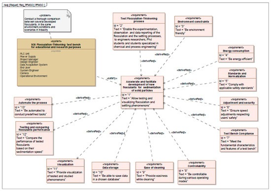
Figure 1.
PFMSO diagram representing the architecture of the designed System of Interest.
The correlation between the system’s performance and its mission highlights the critical necessity for the system to fulfill all mission requirements. Furthermore, the derivation link between the mission and the system’s purpose indicates that the system’s purpose is inherently derived from the mission objectives. To ensure that the system fully accomplishes its mission, the diagram also identifies various sub-missions, each accompanied by its own specific requirements, where applicable.
3.2.3. Defining the System Life Cycle
A thorough understanding of the various phases and the involvement of diverse stakeholders is crucial for comprehending the lifecycle of the laboratory flocculation-thickening system, as illustrated in Figure 2. Table 4 details the key stages of this lifecycle, encompassing planning, design, implementation, testing, and maintenance. Each phase involves distinct stakeholders, including engineers, technicians, researchers, and end users, who contribute through specific roles and responsibilities unique to their expertise.
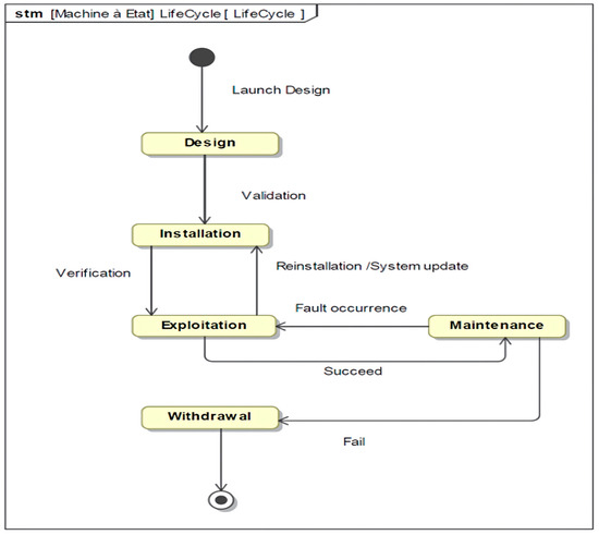
Figure 2.
Life cycle diagram of the flocculation-thickening experimental platform.
Table 4.
Operational and functional stakeholders’ needs.
3.3. Flocculation-Thickening Experimental Platform Using MBSE and CESAM Methodologies
This study employs the MBSE grid and CESAM methodologies to address the challenge of designing a flocculation-thickening experimental platform for research and development applications. The system model is constructed using the CAMEO tool (Cameo Systems Modeler 19.0 LTR SP3, Vélizy-Villacoublay, France) and SysML language. The use of MBSE through the CESAM framework and SysML effectively structured the system components while ensuring the traceability of requirements. For instance, integrating the SysML model allowed linking stakeholder needs (such as safety and ease of use) with technical solutions, including the addition of electric brakes and user-friendly interfaces. The initial phase of the system development process is crucial for identifying stakeholder requirements and defining the system’s boundaries. This paper focuses on the operational analysis of the System of Interest (SOI) as a foundational step, emphasizing the collection of essential information to align the SOI with its intended objectives. Key activities during this phase include gathering stakeholder requirements, creating a PFMSO diagram (Problem, Finality, Mission, System, and Objectives), delineating system boundaries and external interactions, and defining operational use cases. These steps ensure alignment with stakeholder expectations and provide a comprehensive understanding of the problem domain and system objectives. By clearly defining the system’s scope and operational scenarios, this phase establishes a robust groundwork for the subsequent design and development stages.
3.3.1. Defining the System Life Cycle
The practical use cases of the system offer a well-defined framework for identifying the core services it must provide to its users. This step is critical in accurately identifying and defining the requirements of stakeholders. For example, Figure 3 presents the operational use case during the project’s exploitation phase, emphasizing the seven primary services the system is designed to deliver to its users. Out of these, six specific services are related to the test bench’s functions.
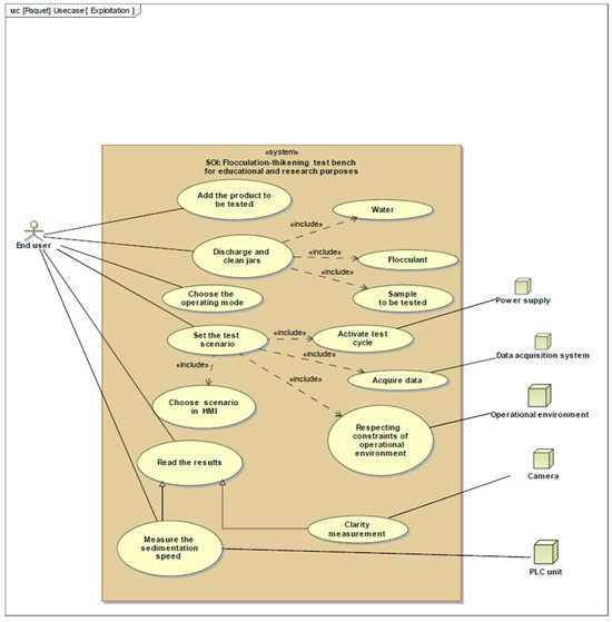
Figure 3.
Operational use case diagram of the flocculation-thickening experimental platform.
The test bench is designed to provide six essential services that contribute to optimizing the flocculation-thickening process. The first service focuses on testing and comparing the performance of various flocculants in settling suspended solids, enabling a systematic evaluation of their effectiveness. The second service aims to optimize key flocculation parameters, including the dosage of flocculants and settling time, to enhance the efficiency of solid removal. Additionally, the test bench facilitates the analysis of settling characteristics for different types of solids, such as clay, organic matter, and inorganic matter, to support the development of more effective treatment processes. Scaling the flocculation process to industrial levels constitutes the fourth service, ensuring that operations achieve peak efficiency in larger-scale applications. Furthermore, the fifth service establishes the test bench as a quality control tool, enabling the continuous monitoring and assessment of flocculation-thickening performance. Lastly, the sixth service positions the test bench as a research platform, fostering the development of innovative flocculants and advancing the understanding of the underlying mechanisms of flocculation and sedimentation. These services offer a comprehensive framework for enhancing the overall efficiency and effectiveness of the flocculation-thickening process. In Figure 4, the operational use case diagram shows the interactions between key actors like the end user, system engineer, data acquisition system, and the PLC unit. The diagram highlights the process of adding samples, selecting test scenarios, activating test cycles, and acquiring data. It also demonstrates the automated measurement of sedimentation speed using the camera and data collection through the PLC unit.
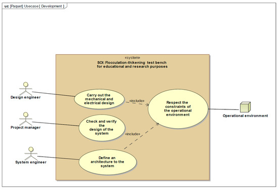
Figure 4.
Development use case diagram for the flocculation-thickening experimental platform.
Figure 4 presents the development use case diagram, illustrating the collaborative roles of the System Engineer, Design Engineer, and Project Manager. The process involves defining system architecture, conducting mechanical and electrical design, and verifying the system’s operational compliance.
3.3.2. Defining the System Life Cycle
The main goal of this study is to evaluate the system’s lifespan while clearly delineating its boundaries and surrounding environment. Figure 5 presents the primary and secondary requirements related to the system of interest (SOI). This requirements diagram serves to formalize the expectations of various stakeholders, both internal and external, concerning the system. It illustrates both functional and non-functional requirements. The purpose of such a diagram is to document these requirements in a way that allows them to be traced to other parts of the model that address them, as well as to the test cases that validate their fulfillment.
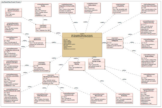
Figure 5.
Requirements diagram for the flocculation-thickening test bench.
3.3.3. Defining the System Life Cycle
The system’s architecture, illustrated in Figure 6, is composed of various elements, including sensors, control systems, and actuators. This diagram illustrates the interactions between the system’s key components, including sensors, the electric motor, and the human–machine interface. Each element is represented to ensure a clear understanding of the data flows and structural relationships within the test bench. The system also includes an electric motor, an emulated load, and a switching mechanism that facilitates the testing of various control strategies. External contributors to the system comprise equipment suppliers, software and hardware providers, regulatory authorities, and academic institutions.
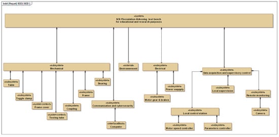
Figure 6.
Bloc diagram definition of the proposed system.
4. Design of Proposed System
The flocculation and decantation workbench is designed to serve as a scalable, precise, and user-friendly platform for conducting experiments related to solid–liquid separation processes. This proposed system integrates mechanical, electrical, and control components to optimize the efficiency and accuracy of flocculation and decantation studies, making it suitable for both research and pedagogical purposes.
4.1. Mechanical Design
The mechanical structure of the pilot-scale laboratory workbench is designed to facilitate the study of flocculation and decantation processes through a system that allows the precise manipulation of test parameters. The design was developed using a system engineering approach, ensuring a simple and efficient solution that meets the functional requirements of the experiments. Figure 7 represents the test bench for the study of flocculation and decantation. The designed test bench consists of six test tubes mounted on a rotating frame. The integrated camera enables real-time observation of the decantation process, providing precise visualization of sediment formation.
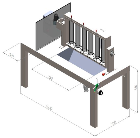
Figure 7.
Test bench for laboratory flocculation-thickening process optimization.
Table 5 details the mechanical components of this test bench along with their respective functions, while Figure 8 illustrates the complete system assembly, providing a clear overview of the 3D design. At the core of the mechanical system is a rotating frame that holds six test tubes. This frame is driven by a gear motor equipped with a brake, which ensures controlled and consistent rotation during the mixing of the flocculent with the test substance. The rotation is transmitted via a coupling mechanism and is stabilized by two high-precision bearings, ensuring smooth and reliable operation. The test tubes are secured within the rotating frame using a frame cover, which is designed for easy operation. The cover is connected by hinges and secured with toggle clamps, allowing quick access for loading and unloading samples. These features are critical for minimizing downtime between tests and ensuring a user-friendly interface. Additionally, the workbench incorporates a sink unit and a siphon to assist in draining and evacuating the test tubes after each experiment. A water gun is included in the design for filling and cleaning the tubes, further streamlining the workflow of the testing process. For monitoring purposes, the decantation process is observed using a camera mounted on the workbench. This camera provides real-time visual feedback, allowing for the precise documentation and analysis of the sedimentation process.
Table 5.
Components of the system.
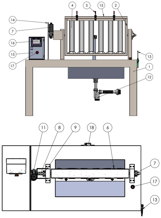
Figure 8.
Workbench main components.
To ensure safety and ease of use, the workbench includes an electrical cabinet protected by a Plexiglas screen to guard against water splashes. The cabinet houses the control unit and electrical components, with a human–machine interface (HMI) providing a simple way to input test parameters and initiate experiments. An emergency stop switch is also integrated into the system, providing a safety mechanism to halt the process in case of any malfunction. This mechanical design offers a robust and flexible platform for conducting flocculation and decantation studies, meeting both research and pedagogical needs.
4.2. Electrical Design and Control System Architecture
The electrical design and control system architecture of the pilot-scale laboratory workbench are essential for ensuring the precise operation and control of the flocculation and decantation experiments. This system integrates various components to allow for the safe and efficient management of the mechanical and process functions.
The core of the electrical system is housed within a dedicated electrical cabinet, which contains the control unit and other critical electrical components. This cabinet is protected by a Plexiglas screen, safeguarding the sensitive electronics from water splashes, which is crucial given the nature of experiments involving liquids. The gear motor is electrically driven and provides rotational movement to the frame holding the test tubes. The integrated brake ensures controlled and safe stopping of the rotation when necessary. The motor is connected to the control unit, allowing the system to manage the speed and duration of rotation based on test requirements. A reliable power supply feeds the entire system, ensuring consistent energy delivery to the motor, camera, human–machine interface (HMI), and auxiliary components. Circuit breakers and fuses are installed to protect the system from overload or short circuits, enhancing safety. Two emergency stop switches are integrated into the electrical design for safety. These switches immediately cut off power to the entire system when activated, ensuring that the workbench can be safely shut down in the event of a malfunction or hazard. The camera, used for monitoring the decantation process, receives its power through a dedicated connection within the electrical cabinet. This ensures a stable power source for consistent video monitoring during the experiment.
The control system of the workbench is managed through a human–machine interface (HMI), which allows the operator to easily input test parameters, monitor the progress of the experiment, and control various aspects of the process. At the heart of the control system is the PLC, which manages the automated functions of the workbench. The PLC is programmed to control the rotation of the frame, adjust the speed of the gear motor, and regulate the timing of the mixing and decantation processes. It also interfaces with the emergency stop switches and other safety features to ensure seamless operation. The HMI serves as the user interface for the operator. It allows for the input of parameters such as rotational speed, the duration of the test, and start/stop controls. The interface is intuitive and designed for ease of use, ensuring that operators can quickly set up and manage tests without complex training. The decantation process is closely monitored by a camera, and additional sensors can be integrated into the system if needed. For example, flow sensors could be added to monitor liquid levels, and pressure sensors could ensure that the system operates within safe limits. Real-time data from the camera and sensors can be fed back to the control system, allowing the operator to make adjustments during the experiment. This closed-loop control ensures that the workbench operates efficiently and that test results are accurate and reliable.
Safety is a critical aspect of control system design. The emergency stop switches provide immediate shutdown capability, and the PLC monitors key operational parameters to prevent overloads or unsafe conditions. The protective screen shields the electrical components from liquid exposure, while the camera allows for visual monitoring without direct interference with the experiment.
5. Conclusions
This study successfully demonstrates the design and implementation of an automated experimental platform for optimizing the flocculation-thickening processes in water treatment, utilizing a Model-Based Systems Engineering (MBSE) approach. By integrating advanced technologies such as PLC programming, sensor systems, and closed-loop control, the bench delivers a highly accurate and efficient platform for studying and optimizing critical parameters in flocculant dosage, mixing speed, and sedimentation time.
The versatility of the test bench allows for the evaluation of various flocculants and their effectiveness in different contexts, offering significant advancements in both research and industrial applications. This is particularly crucial in wastewater treatment where the precise optimization of these processes is necessary to reduce operational costs and improve water quality. Moreover, the test bench provides a scalable solution, making it suitable for both laboratory-scale experiments and larger industrial operations.
Furthermore, the MBSE methodology, incorporating the SysML through the CESAM framework, has proven invaluable in addressing the complexity of system design and ensuring the robust integration of mechanical, electrical, and control elements. The system architecture ensures flexibility and adaptability, enabling researchers to simulate a wide range of operational conditions and gain deeper insights into the underlying mechanisms of flocculation and thickening.
This research opens new perspectives for developing educational and industrial tools in water treatment. In the future, the test bench could be extended to other applications, such as real-time detection of environmental parameters or integration with IoT systems for remote management. Furthermore, leveraging machine learning to analyze collected data could further enhance the optimization of processes.
The developed test bench stands out as a valuable educational and research tool, offering enhanced capabilities for quality control, process optimization, and the development of innovative water treatment solutions. It represents a critical step forward in advancing sustainable wastewater management technologies by providing an efficient, user-friendly, and scalable platform that can be adapted to diverse operational requirements.
Author Contributions
Conceptualization, A.E., M.B.R., N.G., I.M., M.A.D., H.M., C.E., Y.C. and O.L.; methodology, A.E., M.B.R., I.M., C.E. and O.L.; software, N.G., I.M. and M.A.D.; validation, A.E., M.B.R., N.G., I.M., M.A.D. and O.L.; formal analysis, A.E., M.B.R., N.G., I.M., C.E. and Y.C.; investigation, A.E.; resources, A.E., M.A.D. and O.L.; data curation, A.E.; writing—original draft, A.E., M.B.R., N.G., I.M., M.A.D., H.M., C.E., Y.C. and O.L.; writing—review and editing, A.E., H.M., C.E., Y.C. and O.L.; Visualization, A.E., M.B.R., M.A.D., H.M., C.E. and Y.C.; supervision, A.E., M.A.D., H.M. and O.L.; project administration, A.E., M.B.R. and I.M.; funding acquisition, A.E., N.G. and I.M. All authors have read and agreed to the published version of the manuscript.
Funding
This research received no external funding.
Data Availability Statement
The original contributions presented in this study are included in the article. Further inquiries can be directed to the corresponding authors.
Acknowledgments
The authors express their gratitude to the editors and reviewers for their valuable feedback and support in advancing this work.
Conflicts of Interest
The authors declare no conflicts of interest.
References
- Water and Urbanization. Available online: https://www.unwater.org/water-facts/water-and-urbanization (accessed on 10 October 2024).
- Heidari, H.; Arabi, M.; Warziniack, T.; Sharvelle, S. Effects of Urban Development Patterns on Municipal Water Shortage. Front. Water 2021, 3, 694817. [Google Scholar] [CrossRef]
- Liu, M.; Zhang, L.; Wang, M.; Wang, X.; Cui, H.; Wei, J.; Li, X. The Role of Metal-Organic Frameworks in Removing Emerging Contaminants in Wastewater. J. Clean. Prod. 2023, 429, 139526. [Google Scholar] [CrossRef]
- Preparation and Characterization of Spherical Activated Carbons from Oil Agglomerated Bituminous Coals for Removing Organic Impurities from Water—ScienceDirect. Available online: https://www.sciencedirect.com/science/article/pii/S0008622302001197 (accessed on 17 October 2024).
- Tabish, M.; Tabinda, A.B.; Mazhar, Z.; Yasar, A.; Ansar, J.; Wasif, I. Physical, Chemical and Biological Treatment of Textile Wastewater for Removal of Dyes and Heavy Metals. Desalination Water Treat. 2024, 320, 100842. [Google Scholar] [CrossRef]
- Mohamed Noor, M.H.; Ngadi, N. Global Research Landscape on Coagulation-Flocculation for Wastewater Treatment: A 2000–2023 Bibliometric Analysis. J. Water Process Eng. 2024, 64, 105696. [Google Scholar] [CrossRef]
- Radianti, J.; Majchrzak, T.A.; Fromm, J.; Wohlgenannt, I. A Systematic Review of Immersive Virtual Reality Applications for Higher Education: Design Elements, Lessons Learned, and Research Agenda. Comput. Educ. 2020, 147, 103778. [Google Scholar] [CrossRef]
- Maraschin, M.; Ferrari, K.F.S.H.; da Silva, A.P.H.; Carissimi, E. Aluminum Sludge Thickening: Novel Helical Pipes for Aggregation by Dual Flocculation and Thickening by Filtration Applied to Water Treatment Plants. Sep. Purif. Technol. 2020, 241, 116560. [Google Scholar] [CrossRef]
- Li, J.; How, Z.T.; Benally, C.; Sun, Y.; Zeng, H.; Gamal El-Din, M. Removal of Colloidal Impurities by Thermal Softening-Coagulation-Flocculation-Sedimentation in Steam Assisted Gravity Drainage (SAGD) Produced Water: Performance, Interaction Effects and Mechanism Study. Sep. Purif. Technol. 2023, 313, 123484. [Google Scholar] [CrossRef]
- Careaga, J.; Osores, V. A Multilayer Shallow Water Model for Polydisperse Reactive Sedimentation. Appl. Math. Model. 2024, 134, 570–590. [Google Scholar] [CrossRef]
- Gao, R.; Gao, S.-H.; Li, J.; Su, Y.; Huang, F.; Liang, B.; Fan, L.; Guo, J.; Wang, A. Emerging Technologies for the Control of Biological Contaminants in Water Treatment: A Critical Review. Engineering 2024. [Google Scholar] [CrossRef]
- Opitz, J.; Bauer, M.; Alte, M.; Peiffer, S. Development of a Novel Sizing Approach for Passive Mine Water Treatment Systems Based on Ferric Iron Sedimentation Kinetics. Water Res. 2023, 233, 119770. [Google Scholar] [CrossRef] [PubMed]
- Feng, Y.; Gao, G.; Wang, P.; Fu, M.; Zhang, Z. Towards Model-Based Requirements Engineering: Construction Method of Stakeholder Value Networks Model Based on MBSE. Comput. Ind. Eng. 2024, 195, 110398. [Google Scholar] [CrossRef]
- ANSI/EIA632; Processes for Engineering a System. American National Standards Institute (ANSI)/Electronic Industries Association (EIA): Philadelphia, PA, USA, 2003.
- Guennouni, N.; Machkour, N.; Chebak, A. Using MBSE for Operational Analysis of Power Converter for Electric Traction. In Proceedings of the 2021 17th Conference on Electrical Machines, Drives and Power Systems (ELMA), Sofia, Bulgaria, 1–4 July 2021; pp. 1–6. [Google Scholar]
- ISO 12588; Systems and Software Engineering—System life Cycle Processes. International Organization for Standardization (ISO): Geneva, Switzerland, 2023.
- IEEE 1220; IEEE Standard for Application and Management of the Systems Engineering Process. IEEE Standards Association: Piscataway, NJ, USA, 2005.
- Khandoker, A.; Sint, S.; Gessl, G.; Zeman, K.; Jungreitmayr, F.; Wahl, H.; Wenigwieser, A.; Kretschmer, R. Towards a Logical Framework for Ideal MBSE Tool Selection Based on Discipline Specific Requirements. J. Syst. Softw. 2022, 189, 111306. [Google Scholar] [CrossRef]
- Architecture and Principles of Systems Engineering—Charles Dickerson, Dimitri N. Mavris—Google Books. Available online: https://books.google.co.ma/books?hl=en&lr=&id=nFLlkLs-VNMC&oi=fnd&pg=PP1&ots=OgAzzxJNQz&sig=m9wXK2EGP_Ng-LNrD-eEW1GnrzE&redir_esc=y#v=onepage&q&f=false (accessed on 17 October 2024).
- Mazeika, D.; Morkevicius, A.; Aleksandraviciene, A. MBSE Driven Approach for Defining Problem Domain. In Proceedings of the 2016 11th System of Systems Engineering Conference (SoSE), Kongsberg, Norway, 12–16 June 2016; pp. 1–6. [Google Scholar]
- Madni, A.M.; Sievers, M. Model-Based Systems Engineering: Motivation, Current Status, and Research Opportunities. Syst. Eng. 2018, 21, 172–190. [Google Scholar] [CrossRef]
- Delp, C.; Lam, D.; Fosse, E.; Lee, C.-Y. Model Based Document and Report Generation for Systems Engineering. In Proceedings of the 2013 IEEE Aerospace Conference, Big Sky, MT, USA, 2–9 March 2013; pp. 1–11. [Google Scholar]
- Morkevicius, A.; Aleksandraviciene, A.; Mazeika, D.; Bisikirskiene, L.; Strolia, Z. MBSE Grid: A Simplified SysML-Based Approach for Modeling Complex Systems. INCOSE Int. Symp. 2017, 27, 136–150. [Google Scholar] [CrossRef]
- Krob, D. CESAM: CESAMES Systems Architecting Method—A Pocket Guide; CESAM Community: Hoboken, NJ, USA, 2017. [Google Scholar]
- Nikolaidou, M.; Tsadimas, A.; Alexopoulou, N.; Anagnostopoulos, D. Employing Zachman Enterprise Architecture Framework to Systematically Perform Model-Based System Engineering Activities. In Proceedings of the 2009 42nd Hawaii International Conference on System Sciences, Waikoloa, HI, USA, 5–8 January 2009; pp. 1–10. [Google Scholar]
- Cloutier, D.R.; Bone, M. Compilation of SysML RFI- Final Report; Stevens Institute of Technology, School of Systems & Enterprises: Hoboken, NJ, USA, 2010. [Google Scholar]
- Cui, D.; Yang, X.; Li, N. Design of Ground Integrated Testing Equipment Based on MBSE. In Proceedings of the Complex Systems Design & Management; Krob, D., Li, L., Zhang, X., Yao, J., Guo, M., Eds.; Springer Nature: Singapore, 2023; pp. 245–256. [Google Scholar]
- Laayati, O.; El Hadraoui, H.; Guennoui, N.; Bouzi, M.; Chebak, A. Smart Energy Management System: Design of a Smart Grid Test Bench for Educational Purposes. Energies 2022, 15, 2702. [Google Scholar] [CrossRef]
- El Hadraoui, H.; Ahmed, C.; Mourad, Z. Model-Based System Engineering Design of a Versatile Control Test Bench of an Electric Vehicle’s Powertrain for Educational Purpose. In Proceedings of the 2021 3rd Global Power, Energy and Communication Conference (GPECOM), Virtual, 5–8 October 2021; pp. 233–239. [Google Scholar]
- Nagasawa, Y.; Kato, Z.; Tanaka, S. Particle Sedimentation Monitoring in High-Concentration Slurries. AIP Adv. 2016, 6, 115206. [Google Scholar] [CrossRef]
- Ozgun, H.; Ersahin, M.E.; Zhou, Z.; Tao, Y.; Spanjers, H.; van Lier, J.B. Comparative Evaluation of the Sludge Characteristics along the Height of Upflow Anaerobic Sludge Blanket Coupled Ultrafiltration Systems. Biomass Bioenergy 2019, 125, 114–122. [Google Scholar] [CrossRef]
- Kim, M.; Kim, S.; Kim, J.; Kang, S.; Lee, S. Factors Affecting Flocculation Performance of Synthetic Polymer for Turbidity Control. J. Agric. Chem. Environ. 2013, 2013, 28208. [Google Scholar] [CrossRef][Green Version]
- Li, Y.; Xu, Z.; Zhan, X.; Zhang, T. Summary of Experiments and Influencing Factors of Sediment Settling Velocity in Still Water. Water 2024, 16, 938. [Google Scholar] [CrossRef]
- Zhai, L.; Kim, H.C.; Kim, J.W.; Kim, J. Simple Centrifugal Fractionation to Reduce the Size Distribution of Cellulose Nanofibers. Sci. Rep. 2020, 10, 11744. [Google Scholar] [CrossRef]
- Vo, A.; Feng, X.; Smith, W.C.; Zhu, D.; Patel, M.; Kozak, D.; Wang, Y.; Zheng, J.; Ashraf, M.; Xu, X. Analyzing Ophthalmic Suspension Particle Size Distributions Using Laser Diffraction: Placebo Background Subtraction Method. Int. J. Pharm. 2021, 598, 120401. [Google Scholar] [CrossRef] [PubMed]
- Pivokonský, M.; Novotná, K.; Čermáková, L.; Petříček, R. Jar Tests for Water Treatment Optimisation: How to Perform Jar Tests—A Handbook; IWA Publishing: London, UK, 2022. [Google Scholar]
- Ennawaoui, A.; Lalam, K.; Harmen, Y.; El Morabit, A.; Chhiti, Y.; Chebak, A.; Benssitel, M. Cactus Cladode Juice as Bioflocculant in the Flocculation-Thickening Process for Phosphate Washing Plant: A Comparative Study with Anionic Polyacrylamide. Sustainability 2022, 14, 8054. [Google Scholar] [CrossRef]
- Sentis, M.P.L.; Aracil, B.; Lemahieu, G.; Bouzaid, M.; Brambilla, G.; Meunier, G. Numerical Prediction of Long-Term Stability of Liquid Formulations Determined by Visual Observation and Static Multiple Light Scattering. Colloids Surf. A Physicochem. Eng. Asp. 2023, 663, 131070. [Google Scholar] [CrossRef]
- Yuan, M.; Bustamante, H.; Mahmoudi, N.; Gradzielski, M. Colloidal Chemistry in Water Treatment: The Effect of Ca2+ on the Interaction between Humic Acid and Poly(Diallyldimethylammonium Chloride) (PDADMAC). Langmuir 2024, 40, 4108–4121. [Google Scholar] [CrossRef] [PubMed]
- Felix, D.; Albayrak, I.; Boes, R.M. In-Situ Investigation on Real-Time Suspended Sediment Measurement Techniques: Turbidimetry, Acoustic Attenuation, Laser Diffraction (LISST) and Vibrating Tube Densimetry. Int. J. Sediment. Res. 2018, 33, 3–17. [Google Scholar] [CrossRef]
- Hou, J.; Hu, Y.; Yang, Z.; Wu, J.; You, G.; Fan, Y.; Miao, L. Synergistic Coupling of Flocculation and Fenton Reaction for Enhanced Sludge Dewatering: Pivotal Role of Bi-Functional Cationic Tannin. Chem. Eng. J. 2024, 491, 152058. [Google Scholar] [CrossRef]
- Abood, K.; Das, T.; Lester, D.R.; Usher, S.P.; Stickland, A.D.; Rees, C.; Eshtiaghi, N.; Batstone, D.J. Characterising Sedimentation Velocity of Primary Waste Water Solids and Effluents. Water Res. 2022, 219, 118555. [Google Scholar] [CrossRef] [PubMed]
- Zamora-Romero, N.; Villegas-Sánchez, O.A.; de Jesús Martínez-López, M.; Arauz-Lara, J.L.; Vélez-Cordero, J.R. Quasi-1D Sedimentation of Brownian Particles along Optical Line Traps. Opt. Laser Technol. 2023, 161, 109212. [Google Scholar] [CrossRef]
- Lama, S.; Pappa, M.; Brandão Watanabe, N.; Formosa–Dague, C.; Marchal, W.; Adriaensens, P.; Vandamme, D. Interference of Extracellular Soluble Algal Organic Matter on Flocculation–Sedimentation Harvesting of Chlorella Sp. Bioresour. Technol. 2024, 411, 131290. [Google Scholar] [CrossRef] [PubMed]
- Casellas-Salha, C.; Acobas, F.; Bontoux, J.; Moreaud, H. Testing the Flocculation/Coagulation of Wastewater by Granulometric Analysis of Suspended Solids in the Water Using a Laser Diffraction Meter. Water Res. 1981, 15, 969–975. [Google Scholar] [CrossRef]
- Li, C.; Busquets, R.; Moruzzi, R.B.; Campos, L.C. Preliminary Study on Low-Density Polystyrene Microplastics Bead Removal from Drinking Water by Coagulation-Flocculation and Sedimentation. J. Water Process Eng. 2021, 44, 102346. [Google Scholar] [CrossRef]
- Cloutier, R.; Sauser, B.; Bone, M.; Taylor, A. Transitioning Systems Thinking to Model-Based Systems Engineering: Systemigrams to SysML Models. IEEE Trans. Syst. Man. Cybern. Syst. 2015, 45, 662–674. [Google Scholar] [CrossRef]
- Ennawaoui, A.; Hadraoui, H.E.; Chhiti, Y.; Mousaid, I.; Bensitel, M.; Chebak, A. Design of a Flocculation-Thickening Test Bench for Laboratory Operations Using Model-Based System Engineering. In Proceedings of the 2023 3rd International Conference on Electrical, Computer, Communications and Mechatronics Engineering (ICECCME), Tenerife, Spain, 20–21 July 2023; pp. 1–6. [Google Scholar]
- Douglass, B.P. Chapter 1—What Is Model-Based Systems Engineering? In Agile Systems Engineering; Douglass, B.P., Ed.; Morgan Kaufmann: Boston, MA, USA, 2016; pp. 1–39. ISBN 978-0-12-802120-0. [Google Scholar]
- Cloutier, R.; Muller, G.; Verma, D.; Nilchiani, R.; Hole, E.; Bone, M. The Concept of Reference Architectures. Syst. Eng. 2010, 13, 14–27. [Google Scholar] [CrossRef]
- El Hadraoui, H.; Zegrari, M.; Hammouch, F.-E.; Guennouni, N.; Laayati, O.; Chebak, A. Design of a Customizable Test Bench of an Electric Vehicle Powertrain for Learning Purposes Using Model-Based System Engineering. Sustainability 2022, 14, 10923. [Google Scholar] [CrossRef]
- Friedenthal, S.; Moore, A.; Steiner, R. (Eds.) Appendix A—SysML Reference Guide. In A Practical Guide to SysML, 3rd ed.; The MK/OMG Press; Morgan Kaufmann: Boston, MA, USA, 2015; pp. 555–584. ISBN 978-0-12-800202-5. [Google Scholar]


Disclaimer/Publisher’s Note: The statements, opinions and data contained in all publications are solely those of the individual author(s) and contributor(s) and not of MDPI and/or the editor(s). MDPI and/or the editor(s) disclaim responsibility for any injury to people or property resulting from any ideas, methods, instructions or products referred to in the content. |
© 2025 by the authors. Licensee MDPI, Basel, Switzerland. This article is an open access article distributed under the terms and conditions of the Creative Commons Attribution (CC BY) license (https://creativecommons.org/licenses/by/4.0/).