Abstract
The utilization of a high pellet ratio in blast furnace smelting represents a pivotal strategy for achieving green and low-carbon ironmaking, which can improve raw material quality, reduce energy consumption, and decrease CO2 emissions. In this study, the impact of pellet proportion and charging sequence on the burden distribution was investigated using the discrete element method. The results revealed that the pellet mass fraction and the porosity of the ore layer gradually increase from the furnace wall toward the center under different pellet proportion conditions. As the pellet proportion increases, the radial segregation index of the pellets decreases and the porosity of the ore layer slightly increases. Furthermore, alternating charging can reduce pellet rolling, thereby lowering the flowability of the burden. The research outcomes can offer valuable insights for optimizing blast furnace charging operations when using a high pellet ratio, contributing to an improved smelting efficiency.
1. Introduction
In recent years, reducing carbon dioxide (CO2) emissions to cope with climate change has become an urgent concern worldwide. The iron and steel industry accounts for approximately 7–9% of global anthropogenic greenhouse gas emissions. The ironmaking process accounts for about 70% of the total energy consumption and about 90% of the carbon emissions within the entire steel production process. Among these emissions, the blast furnace (BF) is the main contributor [1]. To achieve environmentally friendly and low-carbon development of the iron and steel industry, it is crucial to address the challenges of energy efficiency and emission reduction in the blast furnace process [2,3].
Sinter is commonly used as the primary raw material for blast furnaces due to its superior metallurgical performance, more suitable resource availability, and lower production costs. However, sinter production accounts for a significant proportion of pollution in the ironmaking process. In contrast, the pelletizing process exhibits a notably lower energy consumption and CO2 emissions. Consequently, from the perspectives of environmental sustainability, operational stability, burden composition optimization, and the enhancement of both the economic and technical performances of blast furnaces, increasing the pellet ratio in the furnace burden has emerged as a key trend in modern blast furnace ironmaking [4,5]. Pellets, characterized by relatively uniform particle size, small natural repose angles, and a tendency to roll during charging, exhibit properties that are distinctly different from those of sinter. Increasing the pellet proportion significantly affects burden distribution. The distribution of the burden not only influences the gas flow pattern within the blast furnace but also plays a critical role in shaping the cohesive zone, which in turn affects the furnace’s operational stability. Therefore, in practical blast furnace operations, it is essential to implement a rational charging system to ensure the appropriate burden distribution when operating with a high pellet ratio [6,7,8,9].
Some researchers have employed scaled-down physical models to investigate burden distribution; however, such experiments often face limitations in terms of scalability, insufficient data, and high measurement costs [10,11]. In addition, a considerable number of mathematical models regarding burden distribution have already been proposed [12,13,14,15]. Recently, the discrete element method (DEM) has been widely applied to the blast furnace charging process, proving to be highly significant for elucidating the actual burden distribution patterns in blast furnaces. Consequently, numerous studies have utilized DEM to investigate the movement and distribution of burden during the blast furnace charging process [16,17,18,19,20]. Xu et al. [21] studied the effects of stock line depth, batch weight, and chute angle on the formation of the ore-free zone. The results indicated that as the stock line depth increases, the width of the ore-free zone expands, its thickness decreases, and the ore-to-coke ratio decreases. He et al. [4] used the DEM to examine the distribution behavior of the burden under multi-ring charging conditions and varying pellet ratios. Their findings revealed that the pellet ratio had a considerable impact on both the distribution patterns and the burden profiles at the furnace throat. Zhou et al. [22] investigated the influence of central coke charging, reverse charging, the pellet ratio, and coke platform width on coke collapse and the radial ore-to-coke ratio. Their results suggested that an increased pellet ratio leads to a flatter burden layer profile, which hinders the formation of a new coke platform. Based on these findings, they recommend that the pellet ratio should not exceed 40%. Zhao et al. [23] examined the impact of pellet ratio on the packed bed structure and segregation behavior. Their results revealed that an increase in the pellet ratio leads to a reduction in both the height and top width of the stockpile, while the bottom width expands. Furthermore, the degree of segregation in the pellets at the center of the stock surface was found to rise with higher pellet ratios. Chakrabarty et al. [24] employed the DEM to investigate the impact of a delayed pellet loading time in the furnace burden on its distribution within the hopper. Their findings indicated that this delay influences the positioning of the burden, which in turn affects the hopper output and subsequently alters the radial distribution of the burden layer. Additionally, Agrawal [5] reported that an increase in the pellet proportion enhances the uniformity of the burden distribution, improves gas utilization, and effectively increases permeability.
Extensive research has been conducted on the burden distribution in blast furnaces, providing valuable guidance for burden charging operations. However, studies on the influence of the pellet proportion on burden distribution and segregation, as well as the impact of different charging sequences under a high pellet ratio condition, remain relatively limited. Therefore, to explore these issues, this study developed a geometric model of the blast furnace charging system based on the DEM and analyzed the effects of pellet proportion and charging sequence on burden distribution behavior. The results of this study offer valuable insights for optimizing charging operations under high pellet ratio conditions and provide useful guidance for improving furnace efficiency and performance in the future. The paper is organized as follows: Section 2.1 describes the numerical method (DEM), and Section 2.2 outlines the simulation conditions. Section 3.1 presents the validation of the numerical model, Section 3.2 investigates the effect of the pellet proportion on burden distribution, and Section 3.3 examines the influence of charging sequence on burden distribution. Finally, Section 4 presents the conclusions of the study.
2. Model Establishment
2.1. Discrete Element Method
The discrete element method was firstly proposed by Cundall and Strack [25] and has become a widely recognized and powerful technique for simulating particle systems. This method utilizes Newton’s second law in conjunction with a force–displacement relationship at the particle contact points. In the current study, the elastic contact force was modeled using the nonlinear Hertz–Mindlin no-slip model. The governing equations for the translational and rotational dynamics of particle i are shown in Equations (1) and (2):
where mi, ui, Ii, and ωi are the mass, translational velocity, moment of inertia, and angular velocity of particle i, respectively, and Ni denotes the number of particles in contact with i. A summary of all the forces and torques considered in the model is provided in Table 1 [26,27,28].

Table 1.
Forces and torques acting on particle i.
2.2. Simulation Conditions
The present study references the actual 3000 m3 blast furnace at Tangsteel to establish a geometric model of the charging system of a BF, as shown in Figure 1. To reduce the computation time required for simulations, a simplified approach was adopted for the charging system, omitting the charging hopper while retaining the weighing hopper, rotating chute, and furnace throat. To investigate the impact of varying conditions on the radial and circumferential distribution of the burden, the burden surface was divided into 12 equally sized sectors at 30° intervals, as illustrated in Figure 2a. Additionally, the burden surface was divided radially into 20 sections, as shown in Figure 2b. Once the burden was adequately distributed across the surface, statistical analyses were conducted on the burden information within each sampling area.
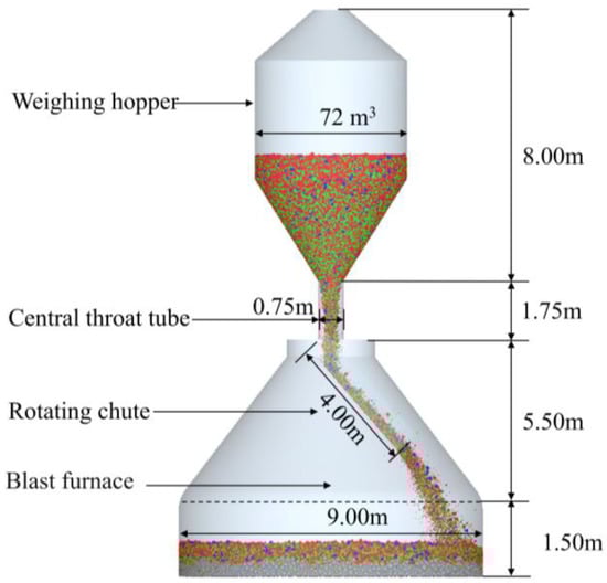
Figure 1.
Geometric model of the charging system used in the simulation.
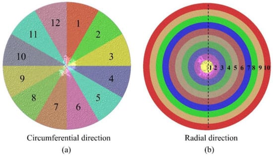
Figure 2.
Circumferential (a) and radial (b) division diagram of BF throat.
In the simulation, both coke and ore are represented as spherical particles, with their size increased to three times the actual size. This adjustment was made to reduce the total number of particles and, consequently, to shorten the simulation duration. This method is frequently used in DEM simulations of the blast furnace charging process [29,30,31,32,33]. The particle size distribution for coke and ore used in the simulation is presented in Table 2, respectively. The batch weight for the coke was 19.53 t, while the batch weight for ore was 87 t. The input ore consisted of a mixture of pellets, lump ore, and sinter, with default proportions of 30%, 15%, and 55%, respectively. All geometric components in the model were assumed to be composed of steel. The simulation parameters used in the DEM were set according to references [34,35,36,37,38] and are listed in Table 3. The charging matrix utilized during the simulation process corresponds to that of the Tangsteel’s blast furnace, as detailed in Table 4.
Table 2.
Particle diameter composition of ore and coke.
Table 3.
Burden parameters used in the simulation.
Table 4.
Charging matrix used in the simulation.
This study investigates the effects of different pellet proportions and charging sequences on the burden distribution. The simulation process is as follows. Initially, the burden was gradually generated at the entrance of the weighing hopper. Once the specified mass of the burden was reached, the burden was discharged from the hopper and distributed through the central throat tube and rotating chute to the furnace throat. The simulation was terminated once all the burden had settled in the furnace throat and movement ceased, resulting in a stable burden layer.
3. Results and Discussion
3.1. Model Validation
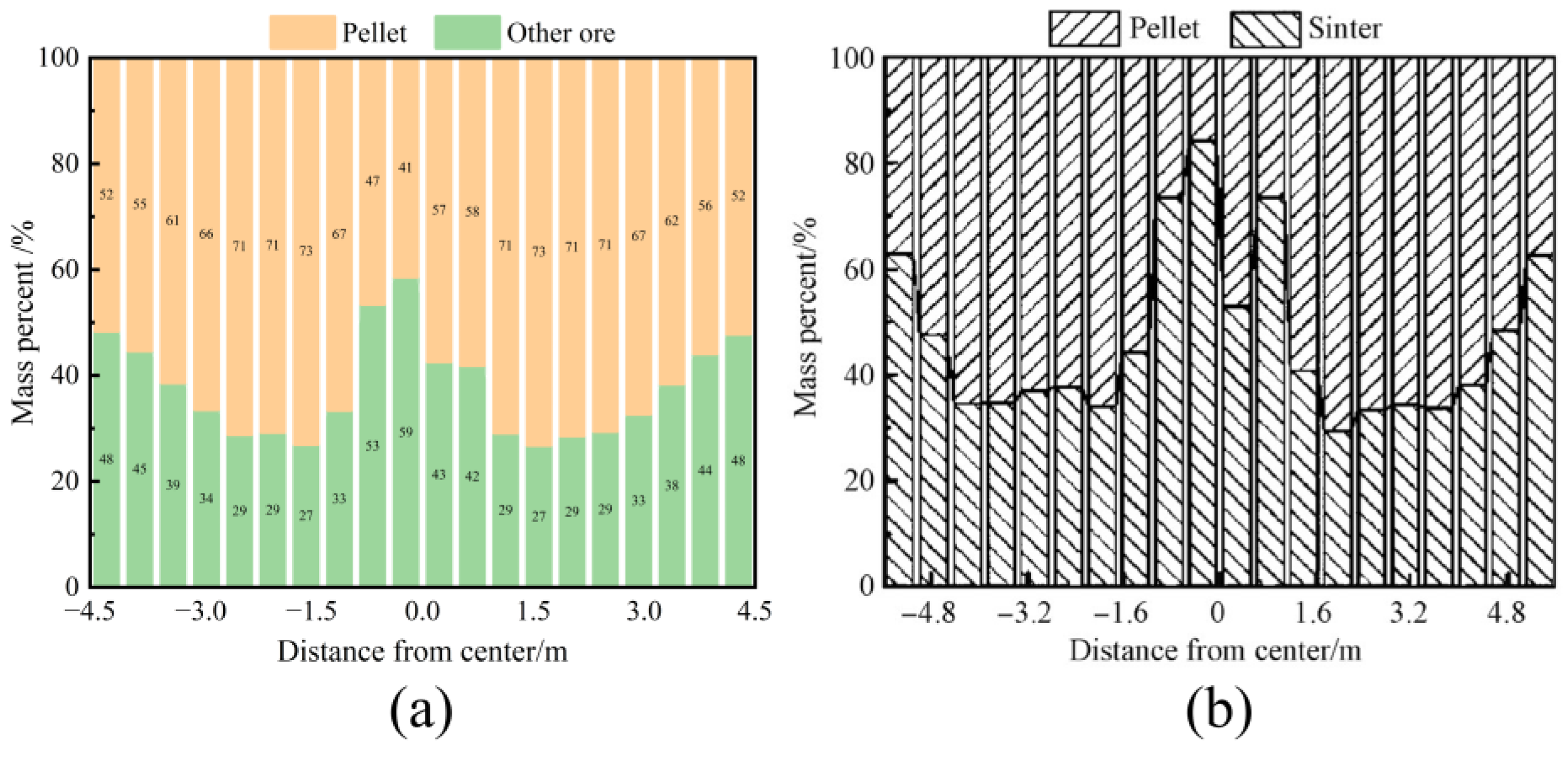
Xu et al. [39,40,41] also studied the impact of different pellet proportion on the burden distribution. They conducted experimental validation of a DEM model using the full-scale model experiment apparatus of an actual 5500 m3 blast furnace. The results showed that the DEM simulation results were in good agreement with the experimental data. To verify the accuracy of the model presented in this study, the simulation results from Xu et al. were compared with the findings of the current research, as shown in Figure 3. When the pellet ratio was 60%, the radial mass percentage distribution of the burden in this study was consistent with Xu et al.’s results, with the pellet ratio gradually increasing from the furnace wall to the center, surpassing the initial pellet ratio. In the center, the pellet ratio decreased in the no-ore zone. Furthermore, the circumferential mass distribution and the variation in porosity of the burden at different pellet ratios showed similar trends in both Xu’s results and those of this study.
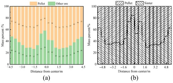
Figure 3.
Radial burden mass percentage distribution of burden layer with pellet proportion is 60%: (a) this paper’s result and (b) Xu’s research result.
3.2. Effect of Pellet Proportion on Burden Distribution
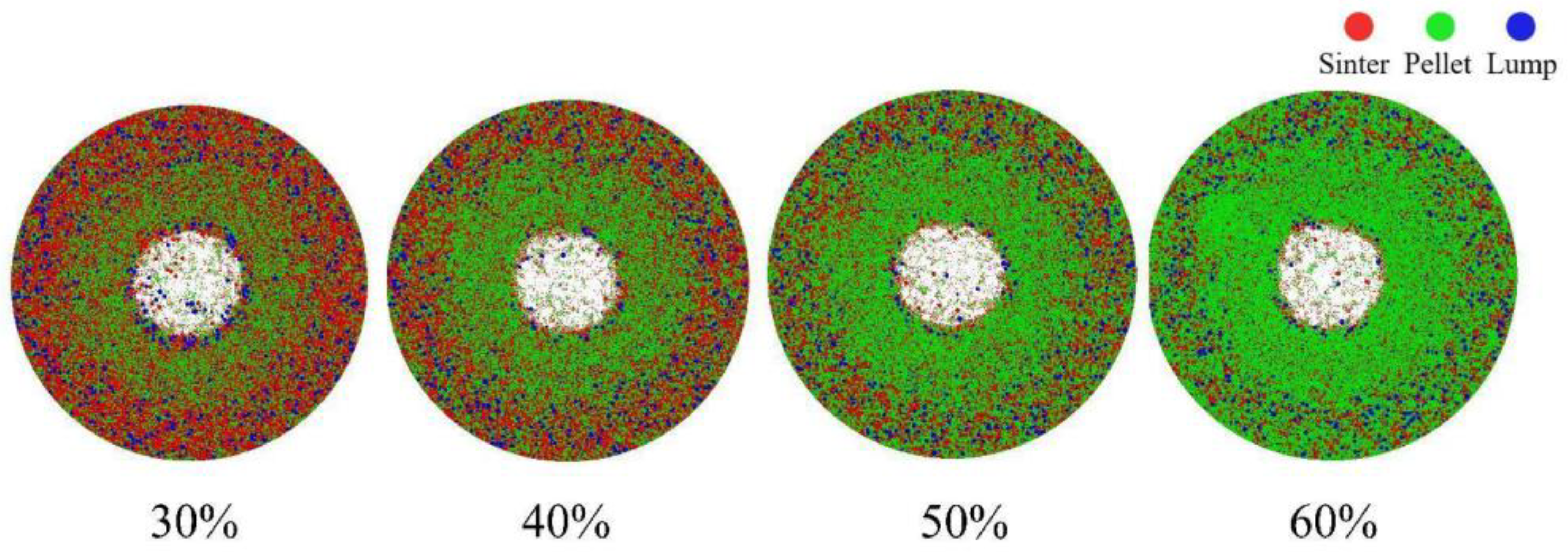
Figure 4 presents the top view of the burden distribution with pellet proportions of 30%, 40%, 50%, and 60%. The different colored particles represent various raw materials: red particles indicate sinter, green particles represent pellets, and blue particles signify lump ore. From the surface of the burden, it is evident that the furnace throat center is not fully covered by the ore, primarily due to the characteristics of the material charging matrix. The figure further shows that as the pellet proportion increases, the presence of pellets in the furnace throat center becomes increasingly pronounced.

Figure 4.
Top view of the stockpile at varying pellet proportions.
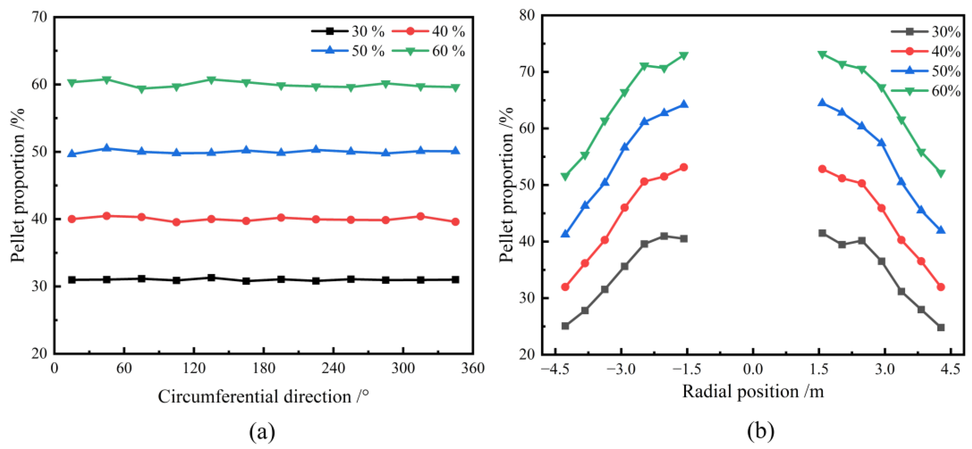
Figure 5a illustrates the circumferential mass distribution of the pellet under different pellet proportions. The results indicate that the distribution of pellets across the circumferential surface is uniform, and the percentage of mass distribution of pellets correlates with the initial burden structure. Therefore, the pellet proportion has little effect on the circumferential mass distribution of the burden. Figure 5b presents the radial mass distribution of the pellets under varying pellet proportions. Due to the lack of ore distribution in the central region, this area was excluded from the analysis. The figure reveals that, for different pellet proportions, the percentage of pellets increases progressively from the furnace wall toward the throat center. Moreover, as the pellet proportion rises, the radial mass proportion of pellet also increases correspondingly. This phenomenon can be attributed to the superior rolling characteristics of pellets. As the pellet proportion increases, more pellets tend to roll towards the central region near the furnace throat, resulting in a reduction in the repose angle and subsequently affecting the overall burden surface profile.
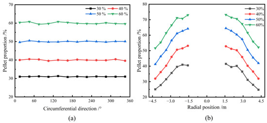
Figure 5.
Effect of various pellet proportions on circumferential (a) and radial (b) mass distribution of pellet on the burden surface.
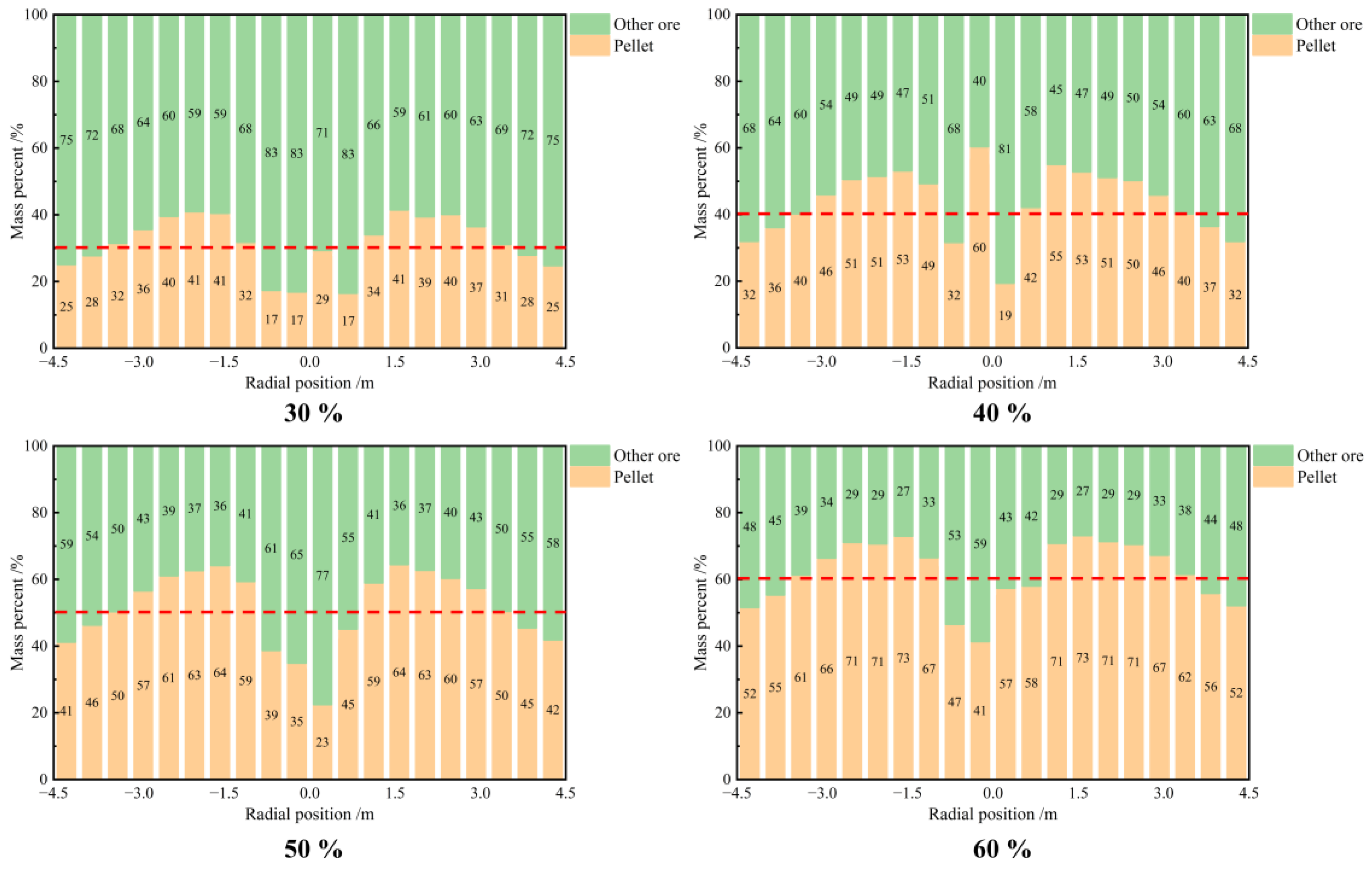
Figure 6 provides a more intuitive representation of the distribution of the radial burden mass percentage under varying pellet proportions. The data indicate that the distribution of pellets across the radial profile is not uniform. The mass percentage of pellets exhibits an inverted “W” shape, increasing from the furnace wall toward the center and exceeding the initial proportion of pellets. However, in the central region, where there is no ore present, the proportion of pellets decreases.
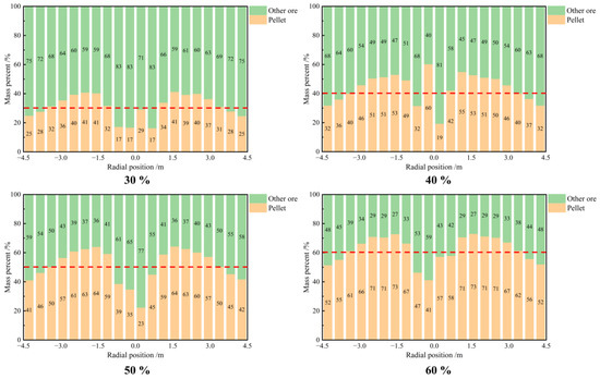
Figure 6.
Distribution of the radial burden mass percentage under varying pellet proportions.
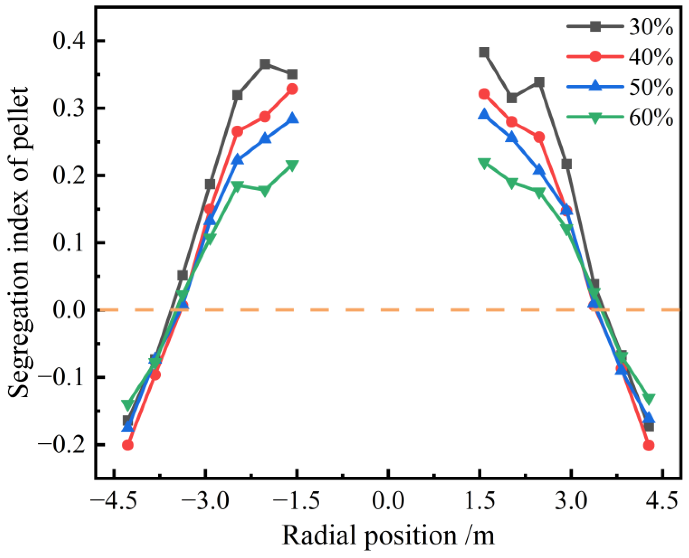
To conduct a clear and quantitative analysis of the burden segregation in the radial position of the furnace throat under varying pellet proportions. This study introduces the segregation index (SI) as a measure of the degree of pellet radial segregation, as shown in Equation (3).
In this equation, SI represents the segregation index of the pellets; denotes the pellet mass fraction at a given radial position; and indicates the initial pellet mass fraction. If the SI equals 0, it indicates that the pellet mass fraction at that position equals the initial mass fraction, signifying that no segregation has occurred. Conversely, if the value of SI at a certain position is too large or too small, it indicates that there is significant segregation here.
As shown in Figure 7, the segregation index of the pellets increases progressively from the furnace wall toward the center. The wall exhibits negative segregation, which indicates that the mass fraction of sinter is higher at the furnace wall. Although the center shows positive segregation, the highest SI reached 0.38, demonstrating that the segregation of pellets is most pronounced at the center of the furnace throat. This is attributed to the superior rolling performance of the pellets, which makes them more prone to rolling towards the furnace’s center when the burden lands on the burden surface. The segregation degree of pellet is nearly 0 at a position with a relative radius of 0.75R, suggesting no segregation occurs at this spot. Furthermore, an increase in the pellet proportion leads to a progressive reduction in the segregation degree of pellets, which suggests a more uniform radial pellet distribution within the furnace.
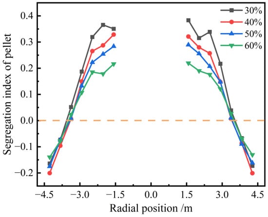
Figure 7.
Radial segregation index of pellet with different pellet proportions.
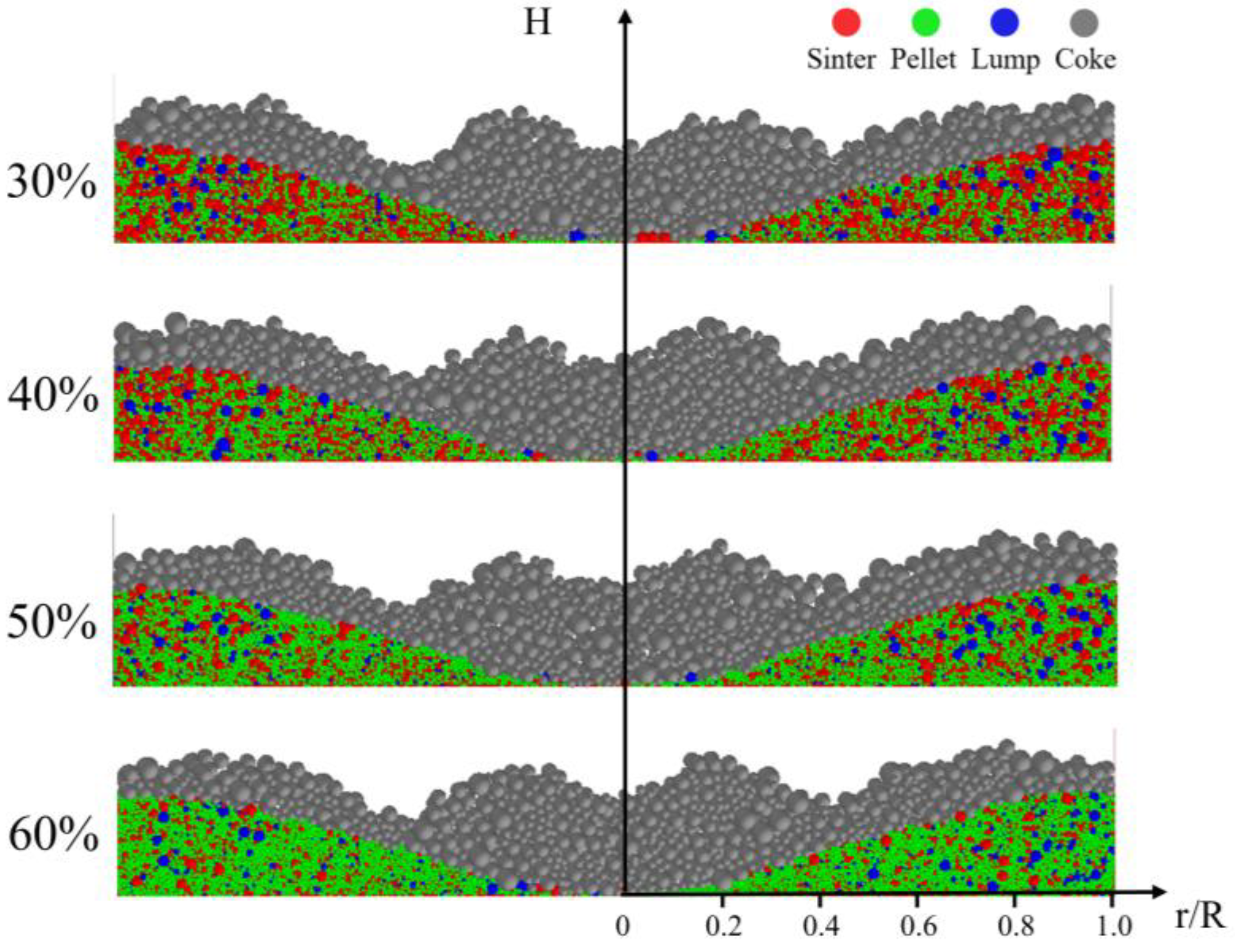
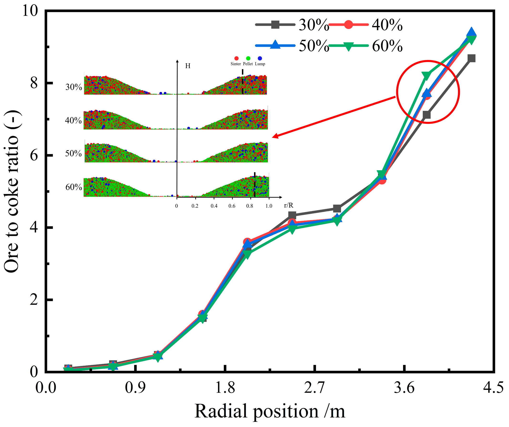
Figure 8 shows the cross-sectional burden distribution of ore and coke in a blast furnace with various pellet ratios. The image reveals that coke tends to concentrate at the center of the furnace throat, where it forms a peak at approximately 0.2R, preventing ore particles from rolling toward the furnace’s center. Figure 9 illustrates the impact of different pellet ratios on the radial ore-to-coke ratio. The trend remains consistent across varying pellet ratios, with the lowest ore-to-coke ratio occurring at the furnace center, gradually increasing toward the furnace wall. As the pellet ratio rises, the ore-to-coke ratio near the wall also increases. This effect is attributed to the reduction in ore platform width at the furnace wall in high-pellet-ratio conditions, leading to reduced coke accumulation and a higher ore-to-coke ratio in that region. In practical blast furnace operations, increasing the pellet ratio can lead to undesirable gas flow distributions, necessitating adjustments to the charging system to achieve optimal gas flow distribution.
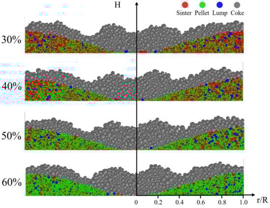
Figure 8.
Distribution of ore and coke layers under different pellet proportions.

Figure 9.
Radial ore-to-coke ratio with different pellet proportions.
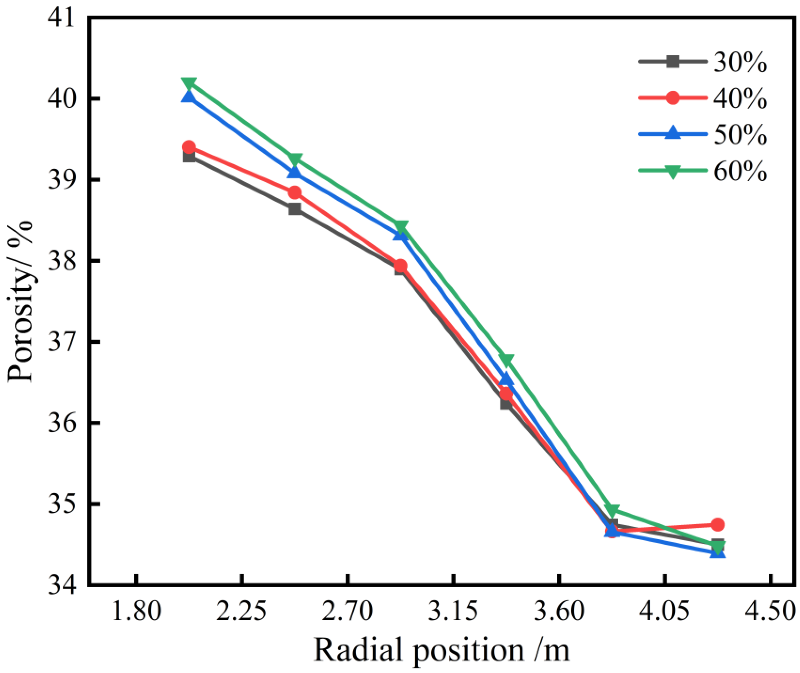
To study the impact of varying pellet ratios on the porosity of the ore layer, a statistical analysis was conducted on variations in porosity from the wall toward the furnace’s center. Six equidistant rectangular regions of equal volume were sampled to calculate the porosity.
Figure 10 shows porosity changes at different radial positions for various pellet ratios. Overall, porosity tends to increase with a higher pellet ratio, albeit to a small degree. This slight increase can be attributed to the narrower particle size distribution of the pellets, compared to the more varied particle sizes of other types of ore. Consequently, when the pellet ratio rises, the more uniform particle size distribution of the pellets results in a more even pore structure, leading to a general increase in porosity. The figure further indicates that the porosity of the ore layer increases gradually from the wall to the furnace’s center. This pattern arises because the ore layer near the furnace wall is thicker, allowing smaller particles to fill the gaps between larger particles, resulting in a lower porosity. Conversely, particles near the furnace’s center tend to roll down in layers, forming a loosely packed structure with a higher porosity.
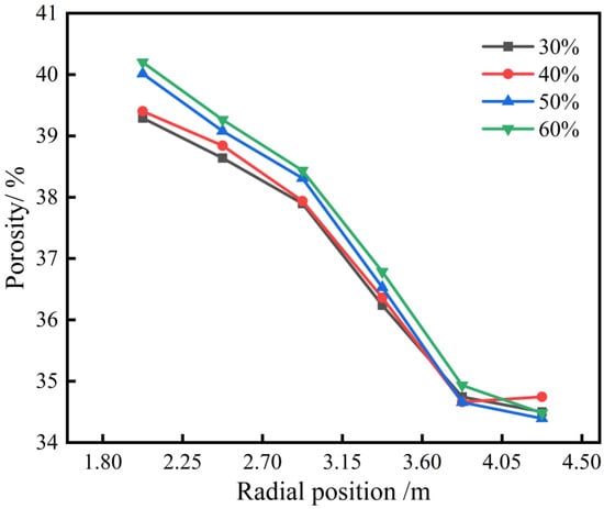
Figure 10.
Effect of different pellet proportions on radial porosity of ore layer.
3.3. Effect of Charging Sequence on Burden Distribution
The charging sequence of different ores in steel plants varies. Sinter, which is typically alkaline, is used in conjunction with acid-forming ores such as pellets and lump ore in the BF. The radial and circumferential uniformity of ore blending at the burden surface has a crucial impact on the position of the softening zone and the properties of the slag. The order in which ores are charged determines their distribution within the ore layers, which in turn plays a critical role in influencing the smelting conditions in the blast furnace.
This study presents a simulation of how different ore charging sequences affect the burden distribution. It is assumed that the ore is uniformly mixed before entering the weighing hopper. During the simulation, ores are introduced sequentially from the hopper inlet according to a specified charging order. Once the desired batch mass is reached, the hopper valve is opened, and the ores are distributed into the blast furnace based on a predefined charging matrix. Based on the actual operations at Tangsteel in Tangshan, China, four different ore charging sequences were established, as shown in Table 5. In the table, “S” denotes sinter, “P” denotes pellets, and “L” denotes lump ore. The adjustment principle for the simulation scheme is to “place sinter on both sides of the ore ring, with pellets and lump ore distributed in the middle of the ore ring”. In the simulation, the proportion of pellets charged into the furnace was set at 60%, with each ore discharge quantity being evenly distributed.
Table 5.
Simulation scheme of different charging sequences.
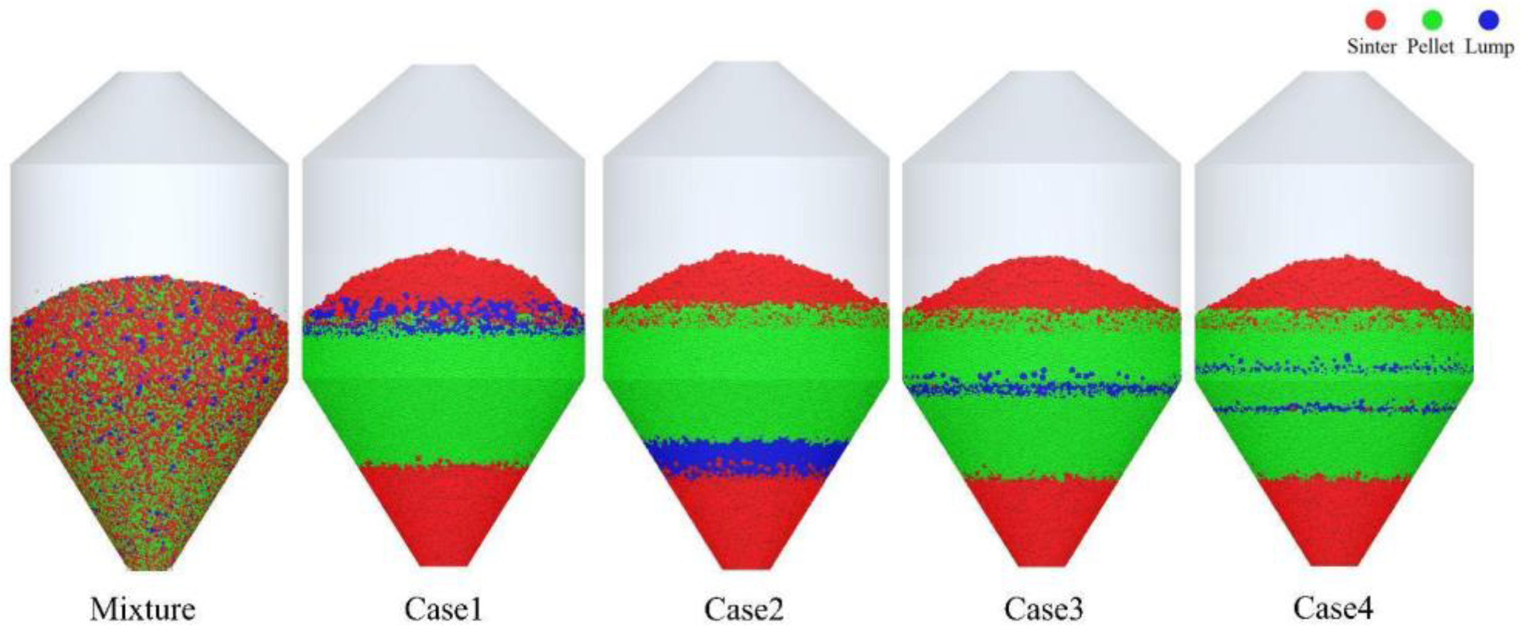
The charging sequence plays a crucial role in determining the distribution of different ores within the hopper, as shown in Figure 11. In the figure, red particles represent sinter, green particles represent pellets, and blue particles indicate lump ore. As depicted in the figure, under all four operating conditions, the distribution of sinter and pellets is generally consistent, which aligns with the adjustment principles of the simulation scheme. However, the position of lump ore within the hopper is determined by the timing of its charging. When a mixed charging strategy is employed, the ores are evenly distributed within the hopper.
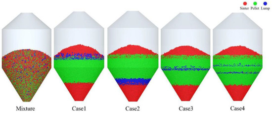
Figure 11.
Burden distribution in the hopper with different charging sequences.
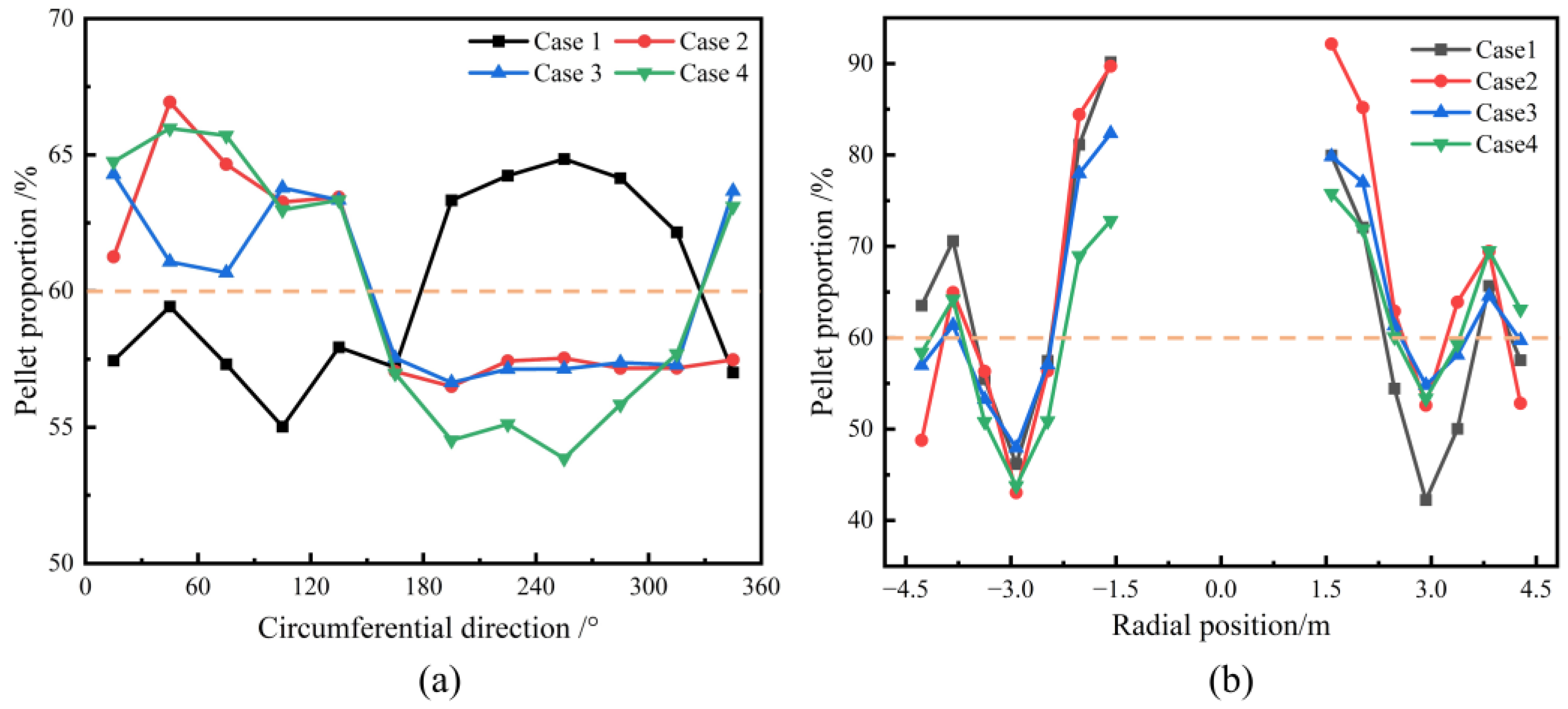
Figure 12a shows the circumferential mass distribution of the pellets under different charging sequences. As seen in the figure, the circumferential distribution of pellets is not uniform, and the pellet mass fraction does not align with the overall burden structure. Under the conditions used for Case 2, Case 3, and Case 4, the circumferential distribution of pellet mass is nearly identical, in contrast to Case 1. Figure 12b presents the radial distribution of pellet mass on the burden surface for different charging sequences. It can be observed that, under all charging sequences, the radial distribution of pellet mass is relatively consistent. From the furnace wall to the center, the mass percentage of pellets initially increases, then decreases, and finally increases again. The pellet mass percentage is highest at the center of the furnace throat. The charging sequence has a significant impact on the burden distribution in the BF. During blast furnace operation, adjustments are made based on actual conditions to ensure a reasonable distribution of the ore both circumferentially and radially, thereby ensuring stable and smooth furnace operation.
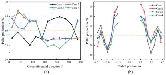
Figure 12.
Effect of various charging sequences on circumferential (a) and radial (b) mass distribution of pellet on the burden surface.
Figure 13 shows the distribution profile of the burden in the ore-coke layer for different charging sequences. The distribution of the ore layer changes significantly by adjusting the charging sequence. Case 1 and Case 2 adjust the charging order of pellets and lump ore, while Case 3 and Case 4 set an alternating charging sequence for pellets and lump ore. The results indicate that, in the center of the furnace throat, the pellet mass fraction is higher in Case 1 and Case 2 compared to Case 3 and Case 4, suggesting that alternating the charging of pellets and lump ore can effectively reduce the rolling behavior of pellets. As the proportion of pellets increases, the alternating charging sequence helps reduce pellet rolling, thereby reducing the flowability of the furnace burden and improving the stability of the airflow distribution.
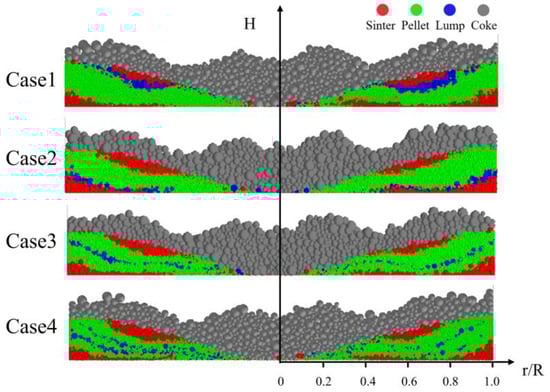
Figure 13.
Distribution of ore and coke layers under different charging sequences.
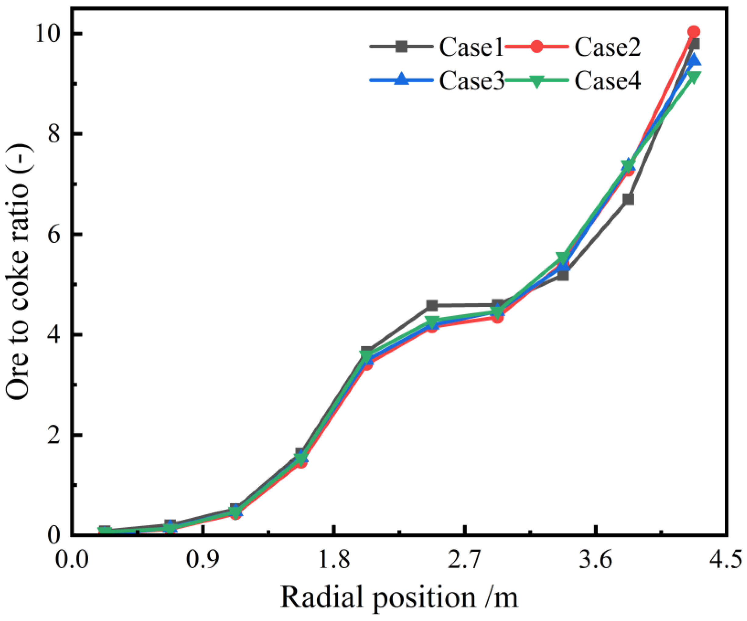
Figure 14 shows the effect of different charging sequences on the radial ore–coke ratio. As seen in the figure, altering the charging sequence has little impact on the radial ore–coke ratio. In all cases, the ore–coke ratio gradually increases from the center of the furnace throat to the wall.
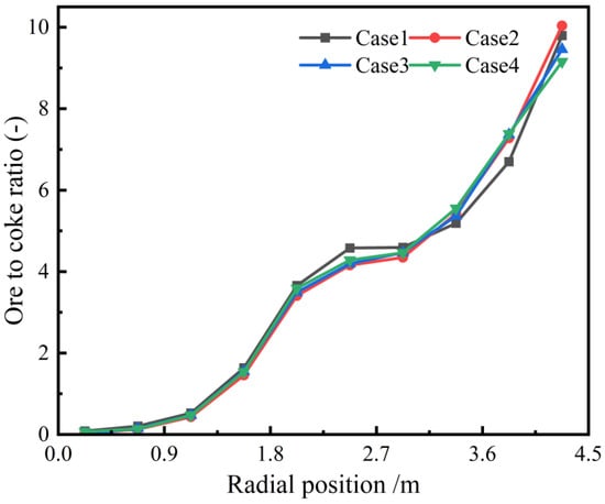
Figure 14.
Radial ore-to-coke ratio with different charging sequences.
4. Conclusions
In this study, the discrete element method was used to investigate the impact of pellet proportion and charging sequence on the burden distribution in a 3000 m3 BF. The conclusions are as follows:
- (1)
- Under different pellet proportion conditions, the pellet mass fraction gradually increases from the furnace wall towards the center. With a higher pellet proportion, the radial segregation index of the pellets diminishes. However, the pellet proportion has a minimal impact on the circumferential mass distribution of the burden.
- (2)
- The porosity of the ore layer increases progressively from the furnace wall to the center. Additionally, with a higher pellet proportion, the porosity tends to increase.
- (3)
- The radial ore-to-coke ratio is minimally affected by variations in pellet proportion and charging sequence.
- (4)
- As the pellet proportion increases, alternating charging can reduce pellet rolling, thereby lowering the flowability of the furnace burden and enhancing the stability of the gas flow distribution.
Author Contributions
Conceptualization, C.Z., H.W., Z.W. and J.Z.; Data curation, C.Z. and P.L.; Formal analysis, H.W.; Funding acquisition, J.H.; Investigation, W.R.; Methodology, C.Z., H.W., Z.W. and Z.C.; Project administration, J.Z. and Z.C.; Resources, J.Z.; Supervision, J.H.; Validation, W.R. and P.L.; Writing—original draft, C.Z. and H.W.; Writing—review and editing, Z.W. All authors have read and agreed to the published version of the manuscript.
Funding
This work was supported by the Interdisciplinary Research Project for Young Teachers of USTB (Fundamental Research Funds for the Central Universities) [Project No.: FRF-IDRY-21-004].
Data Availability Statement
The data that support the findings of this study are available from the corresponding author upon reasonable request.
Conflicts of Interest
Author Jixiang Han was employed by the company SINOSTEEL Equipment & Engineering Co., Ltd. Author Wei Ren was employed by the company SINOSTEEL Equipment & Engineering Co., Ltd. Author Ziluo Chen was employed by the company SINOSTEEL Equipment & Engineering Co., Ltd. The remaining authors declare that the research was conducted in the absence of any commercial or financial relationships that could be construed as a potential conflict of interest.
References
- Tang, C.; Guo, Z.; Pan, J.; Zhu, D.; Li, S.; Yang, C.; Tian, H. Current situation of carbon emissions and countermeasures in China’s ironmaking industry. Int. J. Miner. Metall. Mater. 2023, 30, 1633–1650. [Google Scholar] [CrossRef]
- Wei, H.; Saxén, H.; Yu, Y. Numerical Analysis of Factors Affecting the Burden Surface and Porosity Distribution in the Upper Part of the Blast Furnace. Metals 2023, 13, 292. [Google Scholar] [CrossRef]
- Zhang, J.; Li, Y.; Liu, Z.; Wang, T.; Wang, Y.; Li, K.; Wang, G.; Xu, T.; Zhang, Y. Isothermal kinetic analysis on reduction of solid/liquid wustite by hydrogen. Int. J. Miner. Metall. Mater. 2022, 29, 1830–1838. [Google Scholar] [CrossRef]
- He, L.; Jiang, X.; An, H.; Zheng, H.; Gao, Q.; Shen, F. Effects of pellet ratio on the burden movement and distribution characteristics in the BF throat. Powder Technol. 2024, 432, 119130. [Google Scholar] [CrossRef]
- Agrawal, A. Blast furnace performance under varying pellet proportion. Trans. Indian Inst. Met. 2019, 72, 777–787. [Google Scholar] [CrossRef]
- Mio, H.; Narita, Y.; Nakano, K.; Nomura, S. Validation of the burden distribution of the 1/3-scale of a blast furnace simulated by the discrete element method. Processes 2019, 8, 6. [Google Scholar] [CrossRef]
- Chen, J.; Zuo, H.; Xue, Q.; Wang, J. A review of burden distribution models of blast furnace. Powder Technol. 2022, 398, 117055. [Google Scholar] [CrossRef]
- Li, C.; Dong, K.; Liu, S.; Chandratilleke, G.R.; Zhou, Z.; Shen, Y. DEM study of particle segregation in the throat region of a blast furnace. Powder Technol. 2022, 407, 117660. [Google Scholar] [CrossRef]
- Roeplal, R.; Pang, Y.; Adema, A.; van der Stel, J.; Schott, D. Modelling of phenomena affecting blast furnace burden permeability using the Discrete Element Method (DEM)—A review. Powder Technol. 2023, 415, 118161. [Google Scholar] [CrossRef]
- Mitra, T.; Saxén, H. Discrete element simulation of charging and mixed layer formation in the ironmaking blast furnace. Comput. Part. Mech. 2016, 3, 541–555. [Google Scholar] [CrossRef]
- Mitra, T.; Saxén, H. Investigation of coke collapse in the blast furnace using mathematical modeling and small scale experiments. ISIJ Int. 2016, 56, 1570–1579. [Google Scholar] [CrossRef]
- Chen, J.-S.; Zuo, H.-B.; Wang, J.-X.; Xue, Q.-G.; Wang, J.-S. Mathematical model of burden distribution in bell-less top blast furnace. J. Iron Steel Res. Int. 2023, 30, 216–226. [Google Scholar] [CrossRef]
- Li, H.; Saxén, H.; Liu, W.; Zou, Z.; Shao, L. Model-based analysis of factors affecting the burden layer structure in the blast furnace shaft. Metals 2019, 9, 1003. [Google Scholar] [CrossRef]
- Li, M.; Wei, H.; Ge, Y.; Xiao, G.; Yu, Y. A Mathematical Model Combined with Radar Data for Bell-Less Charging of a Blast Furnace. Processes 2020, 8, 239. [Google Scholar] [CrossRef]
- Wu, D.; Yao, F.; Zhang, D.; Zu, E.; Zhou, P.; Chen, W. A self-adaption growth model for the burden packing process in a bell-less blast furnace. Processes 2024, 12, 1523. [Google Scholar] [CrossRef]
- Chibwe, D.K.; Evans, G.M.; Doroodchi, E.; Monaghan, B.J.; Pinson, D.J.; Chew, S.J. Charge material distribution behaviour in blast furnace charging system. Powder Technol. 2020, 366, 22–35. [Google Scholar] [CrossRef]
- Chen, J.; Zuo, H.; Zhao, H.; Xue, Q.; Wang, J. Burden circumferential mass segregation at the blast furnace with parallel hoppers. Powder Technol. 2022, 409, 117845. [Google Scholar] [CrossRef]
- Wei, H.; Ding, W.; Li, Y.; Nie, H.; Saxén, H.; Long, H.; Yu, Y. Porosity distribution of moving burden layers in the blast furnace throat. Granul. Matter 2021, 23, 10. [Google Scholar] [CrossRef]
- Zhou, K.; Jiang, Z.; Pan, D.; Gui, W.; Huang, J.; Xu, C. Research on the velocity distribution law of the coke in the chute of blast furnace based on discrete element method. Comput. Part. Mech. 2023, 10, 303–311. [Google Scholar] [CrossRef]
- Li, Q.; Guo, S.; Wang, S.; Zou, Z. CFD-DEM investigation on pressure drops of heterogeneous alternative-layer particle beds for low-carbon operating blast furnaces. Metals 2022, 12, 1507. [Google Scholar] [CrossRef]
- Xu, H.; Wang, Y.; Li, C.; Guo, H.; Yan, B. Research on the factors affecting the formation of ore-free zone at blast furnace throat based on DEM. Processes 2023, 11, 967. [Google Scholar] [CrossRef]
- Zhou, H.; Wu, J.; Hong, Z.; Wang, L.P.; Wu, S.; Kou, M.; Wang, G.; Luo, Y. Numerical simulation of coke collapse and its optimization during burden charging at the top of bell-less blast furnace. Powder Technol. 2021, 389, 155–162. [Google Scholar] [CrossRef]
- Zhao, Z.; Saxén, H.; Liu, Y.; She, X.; Xue, Q. Numerical study on the influence of pellet proportion on burden distribution in blast furnace. Ironmak. Steelmak. 2023, 50, 613–620. [Google Scholar] [CrossRef]
- Chakrabarty, A.; Raju, A.B.; Pani, S.; Ghosh, U.; Nag, S.; GSR, M.; Pal, P.; Singh, U. Effect of Selective Pellet Loading on Burden Distribution and Blast Furnace Operations. ISIJ Int. 2023, 63, 271–281. [Google Scholar] [CrossRef]
- Cundall, P.A.; Strack, O.D. A discrete numerical model for granular assemblies. Geotechnique 1979, 29, 47–65. [Google Scholar] [CrossRef]
- Zhang, X.; Wang, N.; Zhou, Z.; Ning, Z.; Chen, M. Effect of combined ferrous burden composition and ore-coke interaction on blast furnace burden distribution. Powder Technol. 2025, 449, 120416. [Google Scholar] [CrossRef]
- Kou, M.; Xu, J.; Wu, S.; Zhou, H.; Gu, K.; Yao, S.; Wen, B. Effect of cross-section shape of rotating chute on particle movement and distribution at the throat of a bell-less top blast furnace. Particuology 2019, 44, 194–206. [Google Scholar] [CrossRef]
- Si, R.; Wang, Z.; Zhang, J.; Dai, J.; Zhang, S.; Jiang, D.; Wei, H. DEM study of the porosity distribution of sinter and coke layers in the throat region of a blast furnace. Powder Technol. 2023, 427, 118755. [Google Scholar] [CrossRef]
- Terui, K.; Kashihara, Y.; Hirosawa, T.; Nouchi, T. Optimization of coke mixed charging based on discrete element method. ISIJ Int. 2017, 57, 1804–1810. [Google Scholar] [CrossRef]
- Mio, H.; Nakauchi, T.; Kawaguchi, Y.; Enaka, T.; Narita, Y.; Inayoshi, A.; Matsuzaki, S.; Orimoto, T.; Nomura, S. High-speed video recording of particle trajectory via rotating chute of Nagoya No. 3 blast furnace and its comparison with simulated behavior using DEM. ISIJ Int. 2017, 57, 272–278. [Google Scholar] [CrossRef]
- Mio, H.; Narita, Y.; Matsuzaki, S.; Nishioka, K.; Nomura, S. Measurement of particle charging trajectory via rotating chute of 1/3-scale blast furnace and its comparing with numerical analysis using Discrete Element Method. Powder Technol. 2019, 344, 797–803. [Google Scholar] [CrossRef]
- Hong, Z.; Zhou, H.; Wu, J.; Zhan, L.; Fan, Y.; Zhang, Z.; Wu, S.; Xu, H.; Wang, L.P.; Kou, M. Effects of Operational Parameters on Particle Movement and Distribution at the Top of a Bell-Less Blast Furnace Based on Discrete Element Method. Steel Res. Int. 2021, 92, 2000262. [Google Scholar] [CrossRef]
- Xu, W.; Cheng, S.; Li, C. Effect of the charging sequence of iron-bearing burden on burden distribution during the charging process of blast furnace based on discrete element method. Ironmak. Steelmak. 2022, 49, 208–216. [Google Scholar] [CrossRef]
- Kou, M.; Zeng, W.; Zhang, Z.; She, X.; Zhang, T.; Zhao, B.; Ma, X.; Zhou, H. Central coke charging and its effect on coke collapse at the throat of blast furnace by DEM simulation. Powder Technol. 2022, 408, 117784. [Google Scholar] [CrossRef]
- Wei, H.; Nie, H.; Li, Y.; Saxén, H.; He, Z.; Yu, Y. Measurement and simulation validation of DEM parameters of pellet, sinter and coke particles. Powder Technol. 2020, 364, 593–603. [Google Scholar] [CrossRef]
- Chakrabarty, A.; Biswas, R.; Basu, S.; Nag, S. Characterisation of binary mixtures of pellets and sinter for DEM simulations. Adv. Powder Technol. 2022, 33, 103358. [Google Scholar] [CrossRef]
- Wei, H.; Li, M.; Li, Y.; Ge, Y.; Saxén, H.; Yu, Y. Discrete element method (DEM) and experimental studies of the angle of repose and porosity distribution of pellet pile. Processes 2019, 7, 561. [Google Scholar] [CrossRef]
- Di, Z.; Yan, B.; Cheng, B.; Wang, S.; Fan, C. Effects of particle size composition and burden ratio on burden segregation in the blast furnace throat based on DEM. Powder Technol. 2024, 448, 120319. [Google Scholar] [CrossRef]
- Xu, W. Investigation on Burden Distribution Segregation Optimization of Blast Furnace and Gas Solid Flow Characteristics in Blast Furnace. Ph.D. Thesis, University of Science and Technology Beijing, Beijing, China, 2020. [Google Scholar]
- Xu, W.; Cheng, S.; Niu, Q.; Hu, W.; Bang, J. The DEM study of segregation phenomena of burden distribution during the charging process of blast furnace with two parallel hoppers. Ironmak. Steelmak. 2020, 47, 337–343. [Google Scholar] [CrossRef]
- Zhang, F.; Xu, W.; Cheng, X.; Chen, Y. Analysis on key process and technology of blast furnace ironmaking on high charging proportion of pellet ore. Iron Steel 2024, 59, 32–45. [Google Scholar]


Disclaimer/Publisher’s Note: The statements, opinions and data contained in all publications are solely those of the individual author(s) and contributor(s) and not of MDPI and/or the editor(s). MDPI and/or the editor(s) disclaim responsibility for any injury to people or property resulting from any ideas, methods, instructions or products referred to in the content. |
© 2025 by the authors. Licensee MDPI, Basel, Switzerland. This article is an open access article distributed under the terms and conditions of the Creative Commons Attribution (CC BY) license (https://creativecommons.org/licenses/by/4.0/).