Abstract
In parallel with the development of data transmission in the telecommunications sector to connect peripheral devices, hardware engineers have defined interfaces for independent communication systems. The basic idea of having standardized interfaces for external devices was quickly extended to control and instrumentation equipment, as the real-time characteristic of distributed systems became a challenge in the field. The proposed Modbus Extension (ModbusE) builds on these new techniques introduced in the UART interface, so that the newly introduced extension retains all the characteristics of the Modbus RTU except for the character bit structure. The validation of the ModbusE protocol allowed the proposal of a new communication message structure, a description of Modbus devices, an acquisition cycle to attain a deterministic temporal response behavior and the definition of an architecture for IIoT integration. In this work, practical research is based on data update times in SMARTConvert software when between 1 and 50 registers are accessed. These registers can, in the most favorable case, be at consecutive addresses and can all be read in a single bus query request, or at addresses 1 to 50, or the registers must be read in separate requests. The contributions of this paper are related to highlighting cases where Modbus modules are incorporated, the addressed registers are not consecutive and the Modbus reads 1 or more holding register records and the ModbusE proposal. As these registers must not be on consecutive addresses, it is necessary to make several requests, defining the function of a Modbus acquisition cycle, adapting the equations to the purpose of the tests carried out, measuring the Modbus communication signals and describing the ModbusE communication concept.
1. Introduction
In fieldbus systems, as in all current communication networks, fieldbus protocols are patterned according to the ISO/OSI layer structure, but in general, only layers 1, 2 and 7 are involved [1]. The minimized and reduced protocol follows the current practice in today’s many automation systems. Often, many buses are small networks with a single segment, and extensions are completed via repeaters or, at most, bridges. The Internet of Things (IoT) and Industrial IoT (IIoT) [2,3], with applicability in the field of smart cities and numerous projects in the building sector, represent another important approach in this domain that successfully uses the OSI stack [4]. IIoT is frequently encountered in production environments; it refers to the industrial sub-set of the Internet, so it is supposed that the IIoT will finally result in Industry 4.0 [5]. IoT stands for the next step in the development of technology on the way to a smarter industrial sector. Everyday devices and objects in the physical world will, for instance, be capable of interacting and exchanging data independent of each other using the Internet, with the aim of providing higher value services and products enabled by data processing and communication technologies [6]. Today, for example, there are major advances in industrial automation, smart building control and processes control technologies, due to the ongoing demand to reduce overall costs and the pressure to incorporate major developments in software and IT. In parallel with IT and computer and communication technologies, embedded computing systems [7] and global interconnections are two main key areas of technological advances.
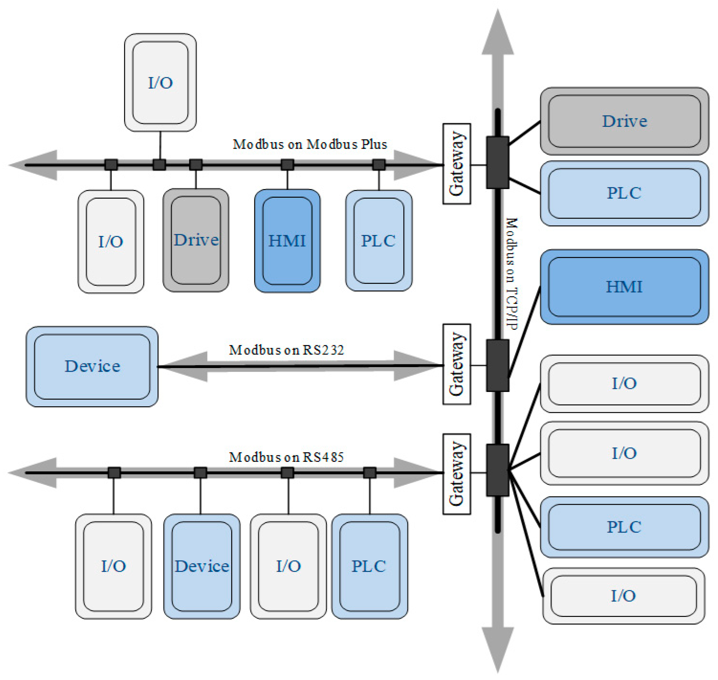
The use of Ethernet has gained popularity in the process automation sector; this is mainly driven by the industry, as decades ago, the use of Ethernet was discussed at the academic level. Ethernet at that time was regarded as inadequate due to a lack of real-time capability. With the adoption of switched Ethernet and changes in communication protocols, these challenges have been relieved. However, although there are yet question marks about the unpredictability of Ethernet, its breakthrough into real-time applications will affect the deployment of fieldbus-based embedded peripherals and perhaps most likely limit the utilization of fieldbus designs in the future. Currently, Ethernet is now replacing mid-level fieldbus systems for connecting PLCs. For client–server communication among connected peripherals on diverse kinds of networks or fieldbus, Modbus employs application-level communication, a layer 7 protocol of the OSI protocol stack. An illustration of a Modbus example network is provided in Figure 1 [6]. As shown, gateways connect devices at the bottom level of the Modbus architecture, HMI (Human Machine Interface) are human–machine interface stations, and PLCs (Programmable Logic Controllers) are programable logic controllers.

Figure 1.
Example of a Modbus network with Gateway, HMI, PLC devices and transport over Modbus MB+, RS232 and RS485.
The Modbus protocol is simple to implement, has a small footprint and is scalable in terms of complexity, field and range. Modbus is easy to manage and improve, open and inexpensive, and its technical datasheets are freely available at [8]; in addition to the de facto standard, it has been standardized by the “International Electrotechnical Commission” (IEC), the “Standardization Administration of China” (SAC) and relevant parts of “Semiconductor Equipment and Materials International” (SEMI) and it offers advanced connections, assistance and experience and deployment tools. The Modbus RTU protocol specifications, managed by the Modbus organization, include the application layer, as well as the data link layer and the physical layer. The Modbus TCP/IP specifications include the application layer and Transport Layer Security, which defines the security for the Modbus TCP/IP implementation [9].
To preserve all the features of the Modbus RTU protocol, ModbusE [10] can have benefits in view of the conflicting conditions arising from bus assignments; thus, no interference can result because the dominant bit wins always and the driver circuits will not be overloaded. It can also be checked to verify whether or not the transmitted data are the same as the incoming data. ModbueE brings a new vision to the Modbus protocol, in addition to the alternatives presented in related works [11,12,13,14], by larger data sizes (16 b, 32 b, 64 b) and the use of multi-microprocessor frames at the physical level, by simplifying the data structure and defining an acquisition cycle (AC) at the data link level and by extending the Cia DS specification to the application level. The results obtained by the authors in accord with the ModbusE protocol refer to the fact that only data and checksum are transmitted in a slot, thus increasing the bandwidth utilization of the communication channel, since headers are no longer transmitted. Data significance is defined either by configuration or by classical Modbus commands in system initialization. Based on ModbusE, data acquisition systems can be developed as modules for digital inputs/outputs, and analog inputs such as voltage, current, resistance temperature detector (RTD), resistance and analog outputs. These modules are supervised by BSGs, which have defined an acquisition cycle. Thus, a timestamp can be added corresponding to the acquisition time of the modules or a timestamp corresponding to the time when data are read from the BSG. These modules, together with the BSG, can be used in any branch of industry where data from different sensors need to be monitored. The connection of the BSG to a PC or other industrial computer is realized by the TCP/IP Modbus protocol. The specific problems to be addressed relate to the synchronization of distributed metering equipment and the acquisition of measurement data across multiple devices in large-scale laboratory setups. The proposed ModbusE extension preserves all features of the Modbus RTU protocol except for the bit structure of a character. To support this, there are benefits to be obtained by taking into account the conflicting situations generated by access to the bus and by being able to check whether or not the data transmitted are identical to the data received.
The rest of this work is structured as follows: Section 2 summarizes related projects using Modbus. Section 3 discusses the mathematical model for evaluating the AC model performance of Modbus transmissions, and Section 4 provides the validation of the existing experimental model. Section 5 and Section 6 present the discussion and final conclusions.
2. Related Work
With respect to the interdependency between the client–server pattern and environmental access control approaches, it is worth mentioning that, in principle, a client–server communication implementation can be realized in both single-master and multi-master systems. In the last case, which can rely on CSMA, TDMA [15] or TP, each master can assume the role of client, while in single-master systems, this function is restricted to the bus master. Therefore, the client–server paradigm is mainly utilized for master–slave systems, exemplified in PROFIBUS [16], ASi [17], Modbus [18], P-NET [19], BITbus [20] and INTERBUS [21], and for RDT at the application level (file transfer, network and device management).
In special management functionalities, the client–server model is also extensively employed in fieldbus systems that structure regular data transmission based on the publisher–subscriber pattern, for instance WorldFIP [22], CANopen [23], DeviceNet [24], EIB, ControlNet [25] or LonWorks [26]. Table 1 shows the comparison of communication protocols and their specific applications. One paper [27] investigates the application of the Modbus protocol and the way to utilize the two types of Modbus protocols to realize the two-layer monitoring network of an energy-saving equipment system based on Modbus-RTU and Modbus-TCP protocols. This paper first discusses the characteristics of Modbus-RTU and Modbus-TCP and their related application scenarios, then describes the design and implementation of a single-layer network relying on Modbus/RTU, which can achieve the monitoring and control of a reduced number of device groups. Subsequently, the authors introduced a 2-layer network based on Modbus/TCP in the network, and the transmission ratio was utilized to achieve control of all node groups. The application of the smart 2-layer network monitoring system in factories, buildings and other scenarios can make device monitoring and management more convenient. The 2-layer network can accomplish the convenient control of a small number of node groups and simultaneous monitoring of equipment, which increases the efficiency of the monitoring and control of equipment scenarios. The obvious representation of cyber-physical systems (CPSs) is surveillance control and acquisition data (SCADA). As SCADA is modernized with enhanced computing and communications technologies, the related risk associated with the further modernization of new technologies should be thoroughly tested and validated. One of the biggest challenges in designing distributed industrial systems is security testing of communication protocols. All CPS systems in service and connected to a physical process cannot be programmed for intrusion testing and validation. A paper [28] describes the design and implementation of an industrial compatible SCADA testbed, formal semantics and security analysis of Modbus/TCP protocol using the Colored Petri Nets (CPNs) instrument. A novel method for attack vector differentiation by identifying influential nodes using formal conceptual analysis is proposed. Thus, the conceptualized Modbus/TCP attack from the analysis is tested and validated on the testbench. One of the major protocols widely used in industrial electronic devices today is Modbus. However, the data produced by Modbus devices might not be comprehensible by IoT applications using different protocols, so they might need to be applied together with a service-level IoT platform.
According to [29], oneM2M is a global IoT standard that can interface different protocols as it provides flexible tools appropriate for building an interworking framework for industrial services. Hence, in this paper, the authors demonstrate an architecture for interworking between devices operating on the Modbus protocol and an IoT platform deployed based on oneM2M standards. In the proposed architecture, the authors discuss how to model Modbus data as oneM2M resources, the mapping rules among them, the procedures required to establish interoperable communication and the optimization methods for this architecture. This paper analyzes the proposed solution and provides an assessment by deploying it on a solar energy management use case. The results demonstrate that the designed model is feasible and can be applied to real scenarios. In [27], the dual-layer network structure composed of Modbus/TCP and Modbus/RTU is not sufficiently detailed and the acquisition cycle is not presented. In [28], it is necessary to investigate the newly introduced framework of formal security analysis and testing for large-scale monitoring, protection and control (WAMPAC). Also, in other additional tests, machines that simulate modbus/TCP can be monitored for ARP spoofing, which can lead to attacker detection. The article [29] can be refined by enhancing interworking proxy entity (IPE) capabilities, including dynamic device registration and semantic support using ontologies. It may also consider adding support for industrial protocols, such as Profibus and Common Industrial Protocol (CIP), so that a wider range of devices could be connected to the IoT network through a single IPE.

Table 1.
Communication protocols comparison and specific applications.
Table 1.
Communication protocols comparison and specific applications.
| Bus Model | Communication Type | Transmission Speed | Bus Topology | Devices Number | Protocol Type | Transmission Media | Specific Implementation Sector |
|---|---|---|---|---|---|---|---|
| ModbusRTU | Serial (RS-232/RS-422/RS-485) | Up to 115.2 kbps | Daisy Chain/Bus | 32 per segment (can be extended to 247 devices with repeaters) | Master–Slave (Single Master) | Twisted pair (RS-485) | Industrial automation and SCADA |
| Modbus TCP | Ethernet | 100 Mbps | Daisy Chain, Star, Tree | Up to 247 servers | Master–slave (client–server) | Ethernet TCP/IP (port 502) | Control systems, industrial automation |
| ModbusE | Serial (RS-485/RS-232) | 27 Mbit/s | Bus | 247 devices with repeaters | Client/server | RS-485 on twisted pair | BIoT, Industrial automation |
| DeviceNet | Serial (CAN-based) | 125 kbit/s, 250 kbit/s and 500 kbit/s | Bus | 64 nodes | Producer/Consumer | Twisted pair (CAN) | Industrial devices, safety devices, large I/O control networks |
| KNX [30] | Serial (RS-232/RS-485) | 9.6 kbit/s (termination resistors not required) | Tree, line or star | Up to 256 per line | Peer-to-Peer, one-to-many, centralized master–slave | Twisted-pair cable, IP, radio or Power line | Building automation, energy management, air-conditioning control (HVAC), security systems, |
| LonWorks | Ethernet, TP/FT, Serial | 5.4 or 3.6 Kbps (Power line), 78 Kbps (TP/FT) | Free topology | 32,385 (127 devices within a domain, up to 255 subnets) | Peer-to-Peer | Twisted pair, fiber optics, wireless Power line | BIoT, HVAC |
| BACnet | Serial (RS-232, RS-485, Ethernet) | 76.8 kbit/s (MS/TP) | line topology | 255 (127 master devices) | Peer-to-Peer, Master–Slave Token Passing (MS/TP) | Twisted pair | Building automation, HVAC, lighting control, access control |
| Interbus-S | Serial (RS-485 based) | 500 kbps | Active ring (Closed-Loop) | 512 devices (16 levels of networks) | Master–Slave | Twisted pair (RS-485) | Process engineering, sensor/actuator, machine production |
| EtherCAT [31] | Serial (Ethernet) | 100 Mbit/s | Line, ring, and star | 65,535 devices on segment | Master-to-slave | Twisted pair, fiber optic | Machine controls |
| CANOpen | Serial (CAN-based) | Up to 1 Mbit/s | Bus | 64 recommended (127 max) | Multi-Master (message and data types) | Twisted pair (CAN) | Industrial machinery, automotive |
3. Communication and Application Aspects of the Modbus RTU Transmission Mode
An example of a Modbus architecture is shown in Figure 1; the basic characteristics of the Modbus protocol are the following:
- Modbus is a request/response protocol that provides services specified by function codes;
- Modbus function codes are elements of Modbus request/response PDUs, making up a Modbus transaction.
Currently, Modbus is implemented using the following communication protocols:
- TCP/IP over Ethernet described in the Modbus Message Implementation Guide.
- Asynchronous serial transmission over a variety of media such as wired (EIA/TIA-232-E, EIA-422, EIA/TIA-485-A), fiber optic, radio, etc.
- Modbus PLUS, which is a high-speed token passing-type network.
There are two serial transmission modes, namely the RTU mode and ASCII mode, so the transmission mode must be the same for all devices on the Modbus serial line. All devices must implement Modbus RTU mode, which is the default mode; the ASCII transmission mode is optional. When the Modbus serial line works using the Remote Terminal Unit (RTU), each byte in the message contains two four-bit hexadecimal digits. The main advantage of this mode is that it allows a higher character density, which implies a higher throughput than the ASCII mode for the same communication speed, each message having to be transmitted as a continuous sequence of characters.
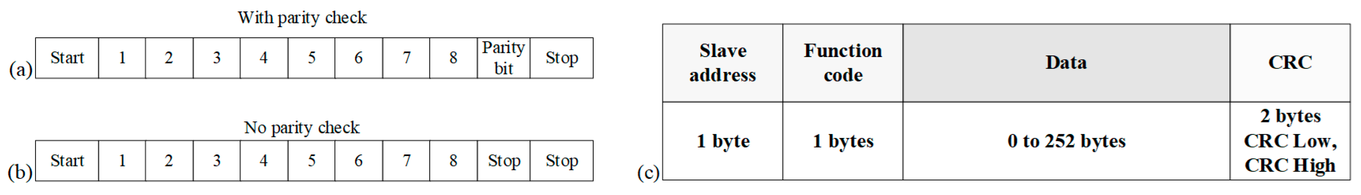
The 11-bit format for each byte in the RTU mode (Figure 2b) is as follows:
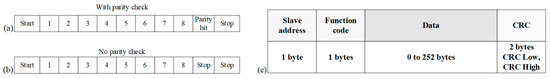
Figure 2.
(a) Bit sequence in RTU mode with parity check; (b) Bit sequence in RTU mode without parity check; (c) Modbus RTU message format.
- The coding system is binary (eight-bit);
- Bits per byte:
- ➢
- One start bit;
- ➢
- Eight data bits with the LSB sent first;
- ➢
- One parity bit;
- ➢
- One stop bit.
Even parity is required, but other modes such as odd parity or no parity can be used. In order to ensure compatibility with other products, the no parity format is also recommended, as no parity requires two stop bits (Figure 2b). Figure 2a,b show the format of the RTU frame, and Figure 2c shows the RTU message framing. How characters are transmitted, including the CRC check field, is shown in Figure 3.
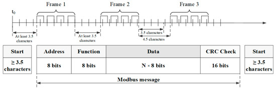
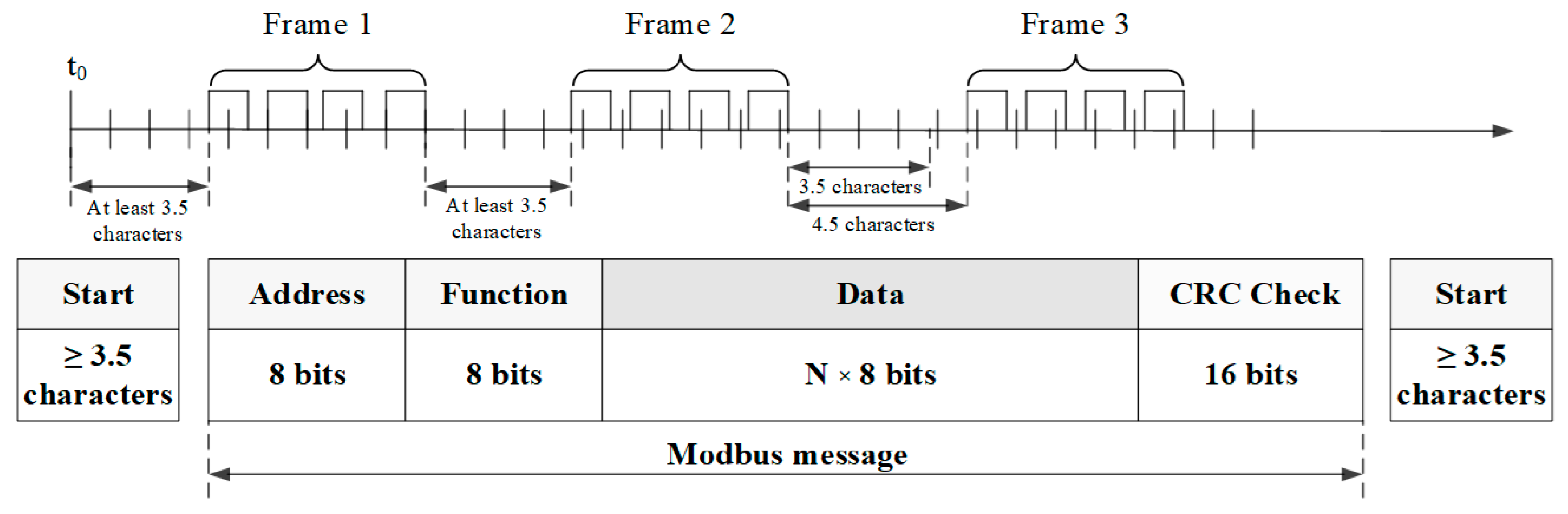
Figure 3.
Modbus RTU message framing.
Partial messages must be identified and errors must be set as a result of this identification. In the RTU mode, message frames shall be separated by a line interval of at least 3.5 characters. This will be referred to as t3.5. The entire message shall be sent as a continuous string.
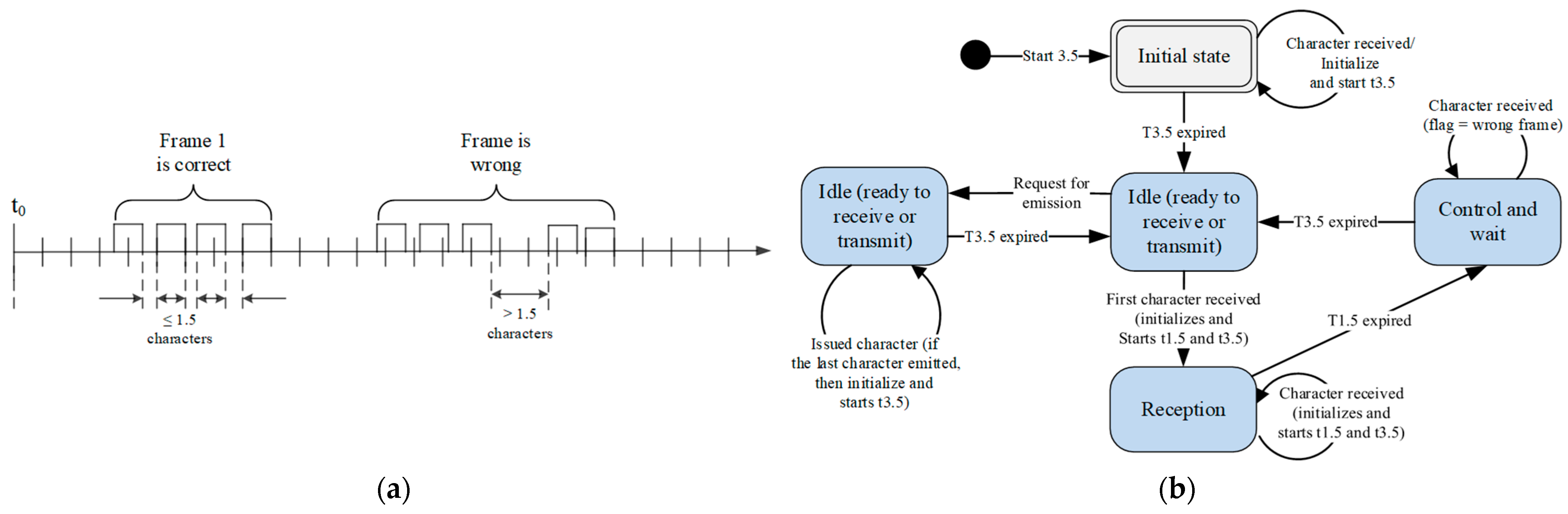
If the silence interval between two characters is greater than the corresponding time of 1.5 characters, the message frame is declared incomplete and must be discarded by the receiver (Figure 4a). An important observation is that the implementation of the RTU receive driver may involve handling a large number of interrupts due to timers t3.5 and t1.5. At high communication speeds, this leads to a significant CPU load. Consequently, these two timers must be strictly observed when the communication speed is equal to or less than 19,200 bps. For speeds higher than 19,200 bps, two fixed values should be used, and it is recommended to use a value of 750 µs between characters (t1.5) and a value of 1750 ms between frames (t3.5) [32]. Within ModbusE, the presence of slots makes it redundant at the gateway to identify the maximum 1.5 character duration between two consecutive characters of the received message as well as the 3.5 character duration which indicates the end of the message, because from the message parsing (slot address, length and CRC), it is possible to check the correctness and presence of the received message, thus avoiding an additional interrupt given by the DMA controller at the end of the message, which can introduce significant additional time at high data rates (above 10 MB/s). Figure 4b shows the state diagram for the RTU transmission mode. Some conclusions on the Modbus state diagram indicate that the transition from the Initial State to the Idle state requires the time t3.5 to expire, ensuring the inter-frame delay [33]. Thus, the Idle state is the normal state when neither transmit nor receive is active. In the RTU mode, the communication line is declared in Idle state if there is no transmission activity after an interval equal to at least 3.5 characters. When the link is in Idle state, each transmitted character detected on the link is identified as a start of frame. The link enters the active state. Then, the end of frame is identified when no character is transmitted after the interval t3.5. After the end of frame detection, the CRC is calculated and the verification is complete. The address field is then analyzed to determine that this frame is for the device. If it is not for the device, then it is discarded. To reduce processing time on reception, the address field can be processed as soon as it is received without waiting for the end of the frame. In this case, the CRC will only be computed and checked if that frame is addressed to the device or is a broadcast frame [34].
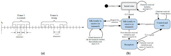
Figure 4.
(a) Character spacing for Modbus RTU frames; (b) Status diagram for Modbus RTU transmission mode.
4. Modbus RTU Protocol Timing Evaluation for Uploading Data Memorized at Scattered Addresses and Proposed ModbusE
4.1. The Function That Defines a Modbus AC
In this paper, research is carried out on the update times of the values on a device that has a maximum of 50 holding register addresses; these holding registers are at scattered addresses, and the communication speed for which the tests will be conducted is 9600 bps.
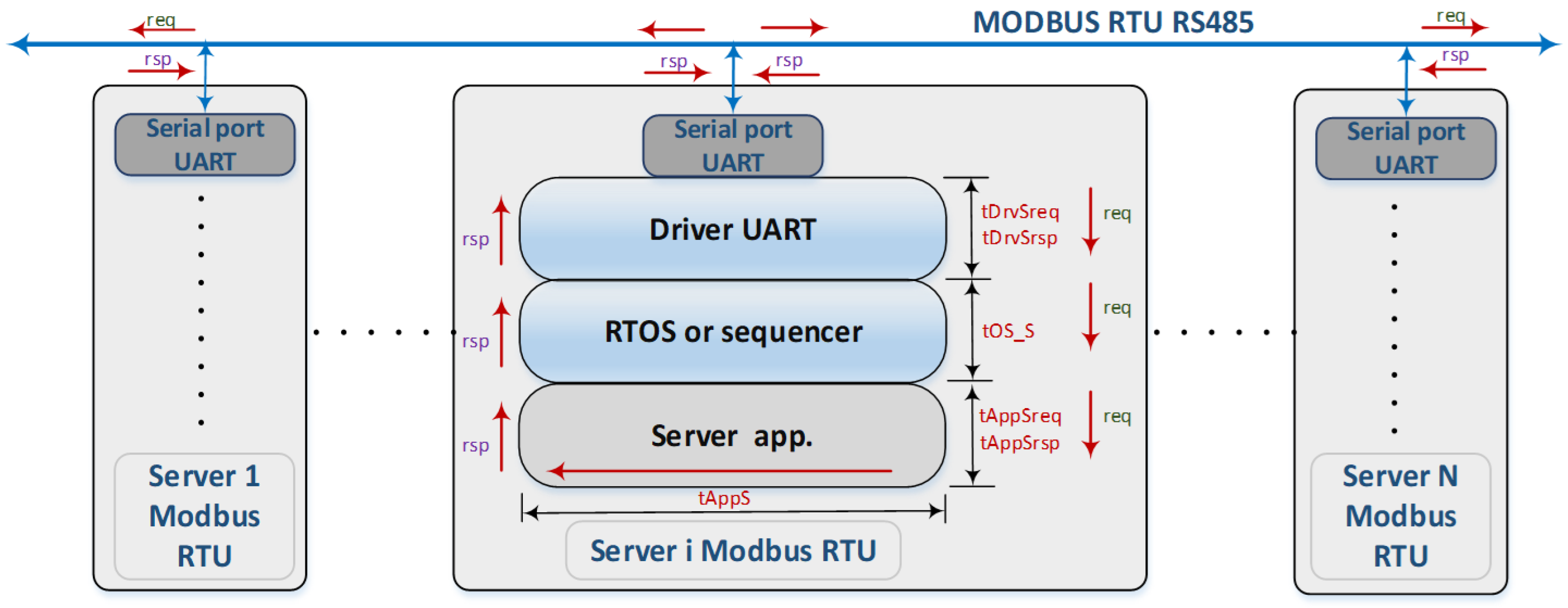
Updating data on Modbus-type devices involves using the method of updating data using a technique called polling, a technique that involves repeatedly scanning the registers on each device. For this purpose, we will first define a mathematical model to facilitate the definition and implementation of the tests necessary to determine the update times of the values from/to a device on a Modbus RTU bus. Figure 5 illustrates the principal message communication scheme, highlighting the different components that could produce measurable delays. For the Modbus protocol, we have shown that it realizes an unconfirmed broadcast communication, valid only for address 0, and a confirmed unicast one, for the other user addresses, namely from address 1 to address 247; the other addresses are reserved, and address 255 is the address determined entirely at the next level. For unicast addresses, Modbus defines a transaction (T) that consists of a request at a client level and a response to that request given by the server that uniquely received the request. For the realized laboratory tests, an emulator application will be implemented on a microcontroller system for a large number of stations. This emulation will allow, using time stamps and markers that can be visualized on the oscilloscope, a much finer measure of the times involved in the update durations of the values on the device. The research requires that the tests be performed for a maximum of 50 holding register addresses. As a result, let us see which functions work with this type of register. From analyzing the control function codes, the possible functions are as follows [34]:
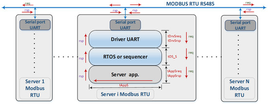
Figure 5.
Support architecture for defining the time needed to describe the mathematical model for the server.
- FC03 (3 in decimal, 0x03 in hex) Read Holding Register: this function code is utilized to read the contents of a contiguous block of holding registers in a remote device.
- FC06 (6 in decimal, 0x06 in hex) Write Single Register: this function code is used to write a single holding register to a remote device.
- FC10 (16 in decimal, 0x10 in hex) Write/Set Multiple Holding Registers: this function code is used to write a block of contiguous registers (1 to 123 registers) to a remote device.
- FC22 (22 in decimal, 0x16 in hex) Mask Write Register: this function code is used to modify the contents of a specified holding register using a combination of an AND mask, an OR mask and the current contents of the register.
- FC23 (23 in decimal, 0x17 in hex) Read/Write Multiple Registers: this function code performs a combination of a read operation and a write operation in a single Modbus transaction.
We defined the Modbus transaction that takes place on the physical Modbus layer. Based on this, we have defined an acquisition slot at the level of a client running on an evolved operating system (e.g., Windows 10). This slot incorporates a single Modbus transaction, and in the following, we define the mathematical model of the AC. At the server level (Figure 5), i.e., Modbus RTU servers connected on the RS485 bus, three components have been identified:
- (1)
- Specific server application;
- (2)
- The RTOS or sequencer (an RTOS was used for testing);
- (3)
- The serial communication driver.
An AC running only on the client consists of any number of acquisition slots which can refer to the following:
- Consecutive, non-blank addresses of Modbus RTU server-type devices;
- Scattered addresses with gaps and with or without consecutive address sequences;
- Interleaved repeating addresses with different control functions or the same control function;
- Performing operations such as reading from one station and sending the value to another station on the same network or on a network connected to another virtual COM or to a Modbus TCP/IP gateway that remotely sends values to another client of a local virtual COM, etc.
The focus of this paper is on a single device from which it is desired to read 50 holding registers whose addresses are scattered. We will try to pursue extreme cases, and possibly an intermediate case, such that the time for the request addressed to the server is given by Equation (1).
where tClientReqi is calculated with Equation (2):
tSiReq(addr_i, FCxx, nrReg) = tClientReqi(addr_i, FCxx, nrReg) + tNETphyReqi(FCxx, nrReg) + tServerReqi(addr_i, FCxx, nrReg)
tClientReqi(addr_i, FCxx, nrReg) = tAppCreqi(addr_i, FCxx, nrReg) + tOS_Ci(FCxx, nrReg) + tSniff(addr_i, FCxx, nrReg) + tDrvCreqi(FCxx, nrReg) + tConvReqi(FCxx, nrReg)
tServerReqi is calculated with Equation (3):
where
tServerReqi(addr_i, FCxx, nrReg) = tDrvSreqi(addr_i, FCxx, nrReg) + tOS_Si (FCxx, nrReg) + tAppSreqi(addr_i,FCxx, nrReg) + tAppSi(addr_i, FCxx, nrReg)
tSiRsp(addr_i,FCxx. nrReg) = tClientRspi(addr_i, FCxx, nrReg) + tNETphyRspi(FCxx, nrReg) + tServerRspi(addr_i, FCxx, nrReg)
tClientRspi(addr_i, FCxx, nrReg) = tAppCrspi(addr_i, FCxx, nrReg) + tOS_Ci(FCxx, nrReg) + tSniff(addr_i, FCxx, nrReg) + tDrvCrspi(FCxx, nrReg) + tConvRspi(FCxx, nrReg)
tServerRspi is calculated as follows:
tServerRspi(addr_i, FCxx, nrReg) = tDrvSrspi(addr_i, FCxx, nrReg) + tOS_Si (FCxx, nrReg) + tAppSrpi(addr_i, FCxx, nrReg) + tAppSi(addr_i, FCxx, nrReg)
According to the relation corresponding to an acquisition slot, Equation (7) results. Hardware delays denoted by tHWnet due to bus drivers or signal spread over long wires may add to the indicated transaction delay, but such latencies are somewhat felt at fast communication rates and are negligible at 9600 bps.
However, the delay may depend on the packet size in nreg, which defines the count of records (Figure 6).
tSi (addr_i,FCxx, nrReg) = tClientReqi(addr_i, FCxx, nrReg) + tServerReqi (addr_i, FCxx, nrReg) + tNETphyReqi (FCxx, nrReg) + tNETphyRspi (FCxx, nrReg) + tClientRspi (addr_i, FCxx, nrReg) + tServerRspi (addr_i, FCxx, nrReg)
tNETphyRspi (FCxx, nrReg) + tNETphyReqi (FCxx, nrReg) = t_TFxxi (FCxx, αi, erri, tout, nrReg) + tHWneti

Figure 6.
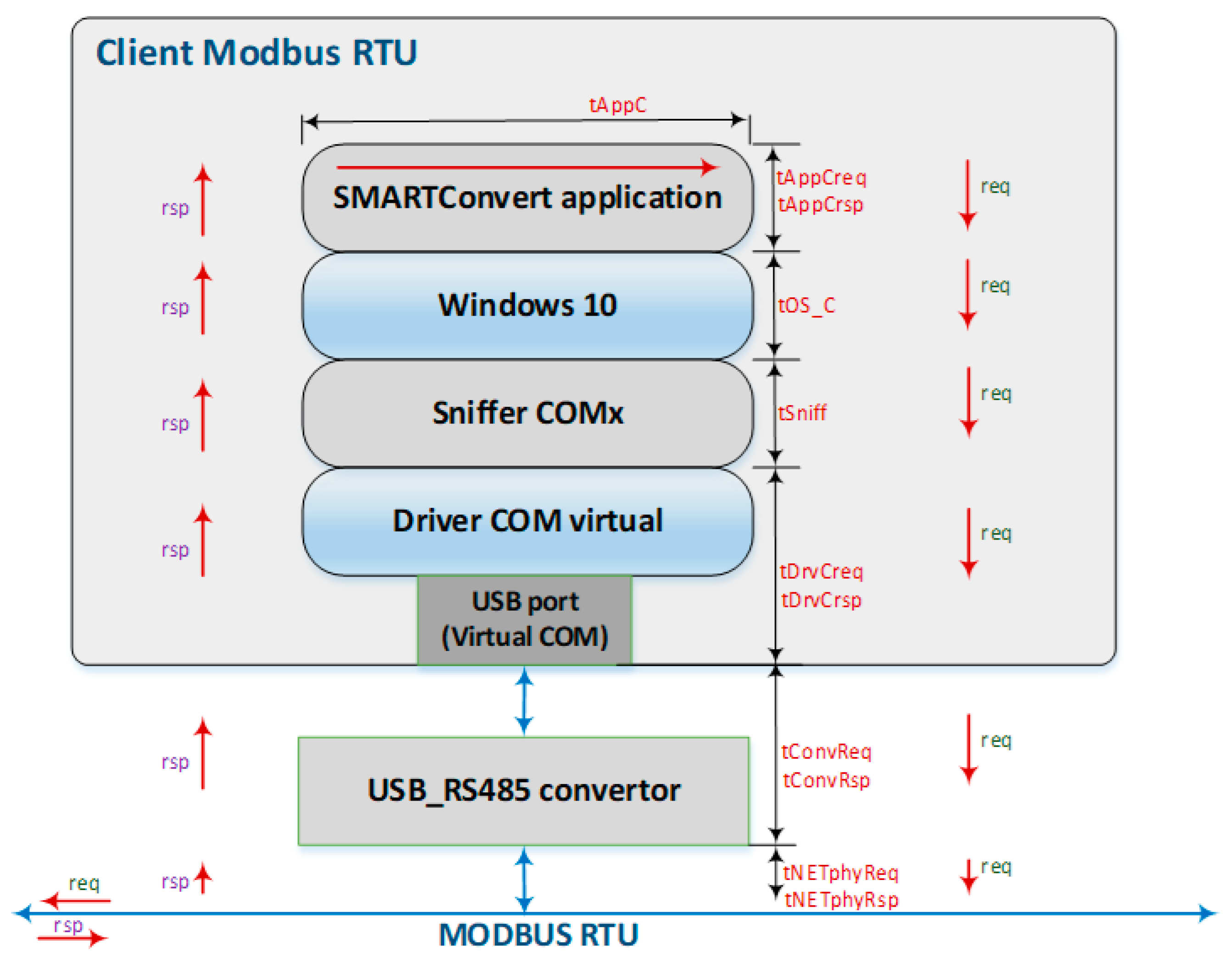
Support architecture for defining the time needed to describe the mathematical model for the Modbus client.
According to the transmission of characters via the Modbus protocol, the parameter α can have values in the interval 0 ÷ 1. α 1, α 2 have been inserted for the Modbus FC03 and FC16 functions, because there are different environments in the message transmission. If the distance between two consecutive transmitted characters is 1.5 characters, as stated by the Modbus standard, the value for α is 1 (maximum value). If there is no delay between the transferred characters, then α is 0, and if a delay is inserted between the transmission of two characters on Modbus, the parameter α is distinct from 0. Substituting the sum of terms 3 and 4 with the value in Equation (8) leads to the following equations.
where
tSi(addr_i,FCxx, nrReg) = tClienti(addr_i, FCxx, nrReg) + tServeri(addr_i, FCxx, nrReg) + t_TFxxi(FCxx, αi, erri, tout, nrReg) + tHWneti
tClienti(addr_i, FCxx, nrReg) = tClientReqi(addr_i, FCxx, nrReg) + tServerReqi(addr_i, FCxx, nrReg)
tServeri(addr_i, FCxx, nrReg) = tServerReqi(addr_i, FCxx, nrReg) + tServerRspi(addr_i, FCxx, nrReg)
In Figure 6, a client has been defined; in this case the SMARTConvert application running on a PC computing system. The only place where we can monitor activity on the client device is at the sniffer level. It is possible that this message path is not really very accurate, so clarifications will be made in lab tests. Thus, four components were highlighted:
- SMARTConvert application;
- The operating system, in the case of the lab tests using Windows 10;
- The sniffer that monitors messages on the virtual COMx (Modbus Poll, Witte Software, v. 7.2, 2019);
- USB driver.
4.2. Customization of Modbus Communication Equations Depending on the Considered Acquisition Cycle
In terms of particularizing the relationships for the purpose of this article, we first define the set of acquisition cycle slots (AC_S) for the case where there is a read for each register located at a register address unique to that register. For this case, we have 50 registers, and the AC_S can look like the one rendered in Equation (12).
AC_S (adr, FC_xx, adrReg, nrReg) = {
(5,3,3,1), (5,3,5,1), (5,3,7,1), (5,3,9,1), (5,3,11,1), (5,3,13,1), (5,3,15,1),
(5,3,17,1), (5,3,19,1), (5,3,21,1), (5,3,23,1), (5,3,25,1), (5,3,27,1), (5,3,29,1),
(5,3,31,1), (5,3,33,1), (5,3,35,1), (5,3,37,1), (5,3,39,1), (5,3,41,1), (5,3,43,1),
(5,3,45,1), (5,3,47,1), (5,3,49,1), (5,3,51,1), (5,3,53,1), (5,3,55,1), (5,3,57,1),
(5,3,59,1), (5,3,61,1), (5,3,63,1), (5,3,65,1), (5,3,67,1), (5,3,69,1), (5,3,71,1),
(5,3,73,1), (5,3,75,1), (5,3,77,1), (5,3,79,1), (5,3,81,1), (5,3,83,1), (5,3,85,1),
(5,3,87,1), (5,3,89,1), (5,3,91,1), (5,3,93,1), (5,3,95,1), (5,3,97,1), (5,3,99,1),
(5,3,101,1) }
From a timing point of view, the t_TFxxi function is not affected by address value or register address. This time, we send 50 time-identical messages on the Modbus bus.
The relation for the AC time can be written as follows:
tAC = 50 × tAll (5,FC03,1) + 50 × t_TF031 (FC03,α1,err1,tout,1)
And in this scenario, as in the case of consecutive addresses, we can have seven cases at slot level:
- If the message is received correctly, then t_TF03i and tAC are calculated with Equations (14) and (15) as follows:t_TF03i (FC03,α1,0,0,1) = (20 + 1 × (2 +3 α) + 18 α) × 10 × 104.17 = (22 + 21 α) × 1041.7 = 22917.4 + 21875.7 α (us) = 22.9174 + 21.8757 α (ms)tAC = 50 × tAlli(5,FC03,1) + 50 × (22.9174 + 21.8757 α) (ms)tAC = 50 × tAlli(5,FC03,1) + 1145.87+ 1093.785 α (ms)
- If for Equation (16) the parameter α is 1, thentAC = 50 × tAlli(5,FC03,1) + 2239.655 (ms)
- If α = 0, then the AC time becomestAC = 50 × tAlli(5,FC03,1) + 1145.87 (ms)
- In case of an error message, the function t_TF03i can be written with Equation (19).t_TF03i(FC03,α,1,0,x) = t_TF03ERR = (20 + 18 α) × 1041. 7 = 20,834 + 18,750.6 α
- If α = 1, thent_TF031(FC03,1,1,0,x) = 39,584.6 (us) = 39.5846 (ms)tAC = 50 × tAll (5,FC03,1) + 1979.23 (ms)
- If α is zero, thent_TF031(FC03,0,1,0,x) = 20,834 (us) = 20.834 (ms)tAC = 50 × tAll(5,FC03,1) + 1041.7 (ms)
- For the case of a timeout, with multiple transactions, it is harder to pinpoint the time period associated with this delay. Any timeout adds about TOUT-50 ms, where TOUT is around 500 ms, and scattering the regions certainly adds additional time to read them.
From a theoretical point of view, we were able to calculate, depending on α and possibly timeout in extreme cases, the traffic duration on the Modbus RTU hardware bus. Further findings on tAlli times will be conducted experimentally at the microcontroller level emulating Modbus RTU servers and with a sniffer for Virtual COM at the client level running on the PC.
Since there are no Modbus stations available to fulfill the requirements of the experiment, an application was realized on a STM32F7 Discovery development kit on which 247 stations each with 50 holding registers were emulated. In the case of the subject of this article, one of the stations can support the required conditions; the application was also designed for the situation that requires the use of all addresses for the user, from 1 to 247. For the implementation of the acquisition cycle, it was decided to dispense multiple RTOS tasks to eliminate the time given by task switching, and loop testing allows almost instantaneous CRC computing (with very minimal delay), elimination of delays given by interrupt responses and scheduling of DMAs on transmit and receive. On the other hand, the Cortex M0 performs this task only for the purpose of increasing slot-level efficiency and hence the acquisition cycle. The communication between processors is realized using a flag for the Cortex M0 and the dedicated interrupt for the Cortex M4. The required Modbus functions are available for these 50 registers at each server station, namely FC03 for reading and FC16 for writing. The connection between the PC and the development kit was realized with a USB to GPIO converter kit on the serial port identified as Prolific USB-to-serial-Comm Port (for ex. COM10).
Function 03 (0x03) (read memory registers (hold values)) is used to read the contents of a number of memory registers from a remotely accessed device. The request PDU specifies the starting register address and the number of registers. In the PDU, the registers can be addressed starting with address zero; thus, registers numbered 1 through 16 are addressed with addresses 0 ÷ 15. The register data in the response message are packaged as two bytes for each register, with the right-aligned binary contents for each byte, and for each register, the first byte contains the upper bits and the second byte contains the lower bits. The response time for function F03 is calculated as follows:
t_rspF03 = t_rspOkF03 = (1 address + 1 FC + 1 the number of records) + nrReg × 2 + CRC = 3 + nrReg × 2 + 2 = (5 + nrReg × 2) × frames
4.3. Modbus Communication Platform Testing for the Case When Registers Are at Scattered Addresses
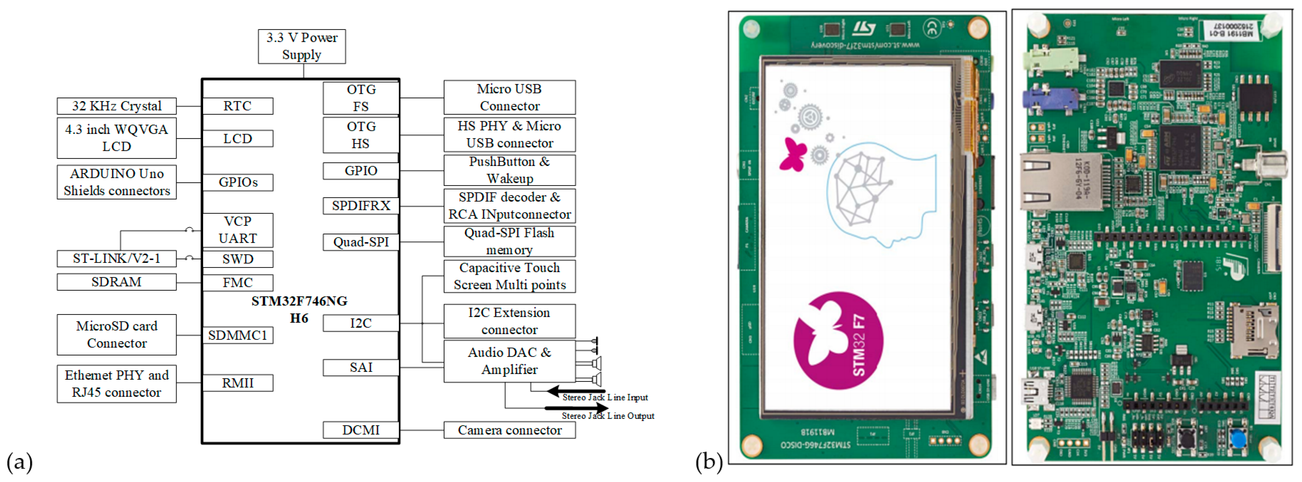
The hardware architecture of the development kit is shown in Figure 7. Among the most important features are the following:
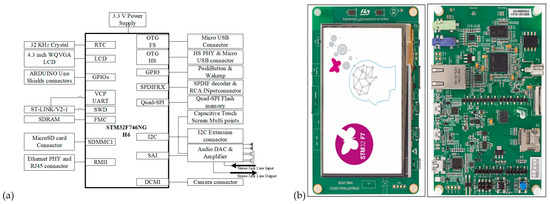
Figure 7.
(a) Hardware architecture of 32F746GDISCOVERY development kit (STM32F746G-DISCO with STM32F746NG); (b) The two layers of the STM32F746GDISCOVERY kit.
- STM32F746NGH6 microcontroller (produces by STMicroelectronics, Geneva, Switzerland) equipped with 1MB of flash memory and 340 KB of RAM [35];
- On the board flash programming support and ST-link/V2-1 debugging with USB connection;
- 128 Mbit flash memory with Quad-SPI connection and 128 Mbit SDRAM (64 Mbit accessible);
- MicroSD card connector, Arduino Uno V3 connector and 4.3 inch 480 × 272 color LCD-TFT with capacitive touch screen;
- Free software that includes a multitude of examples, part of the STM32Cube package.
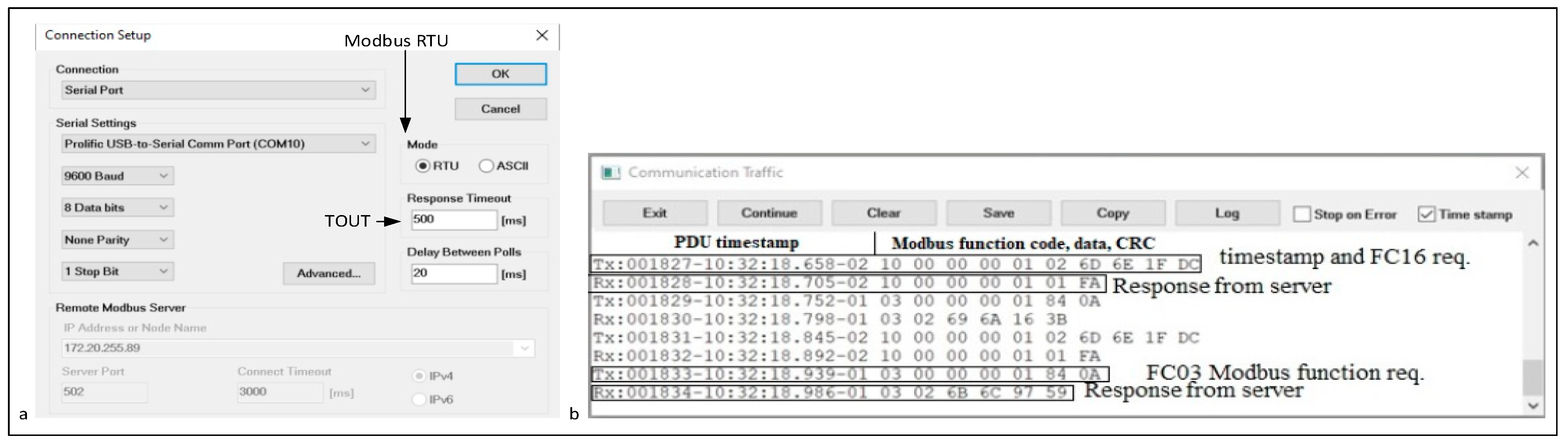
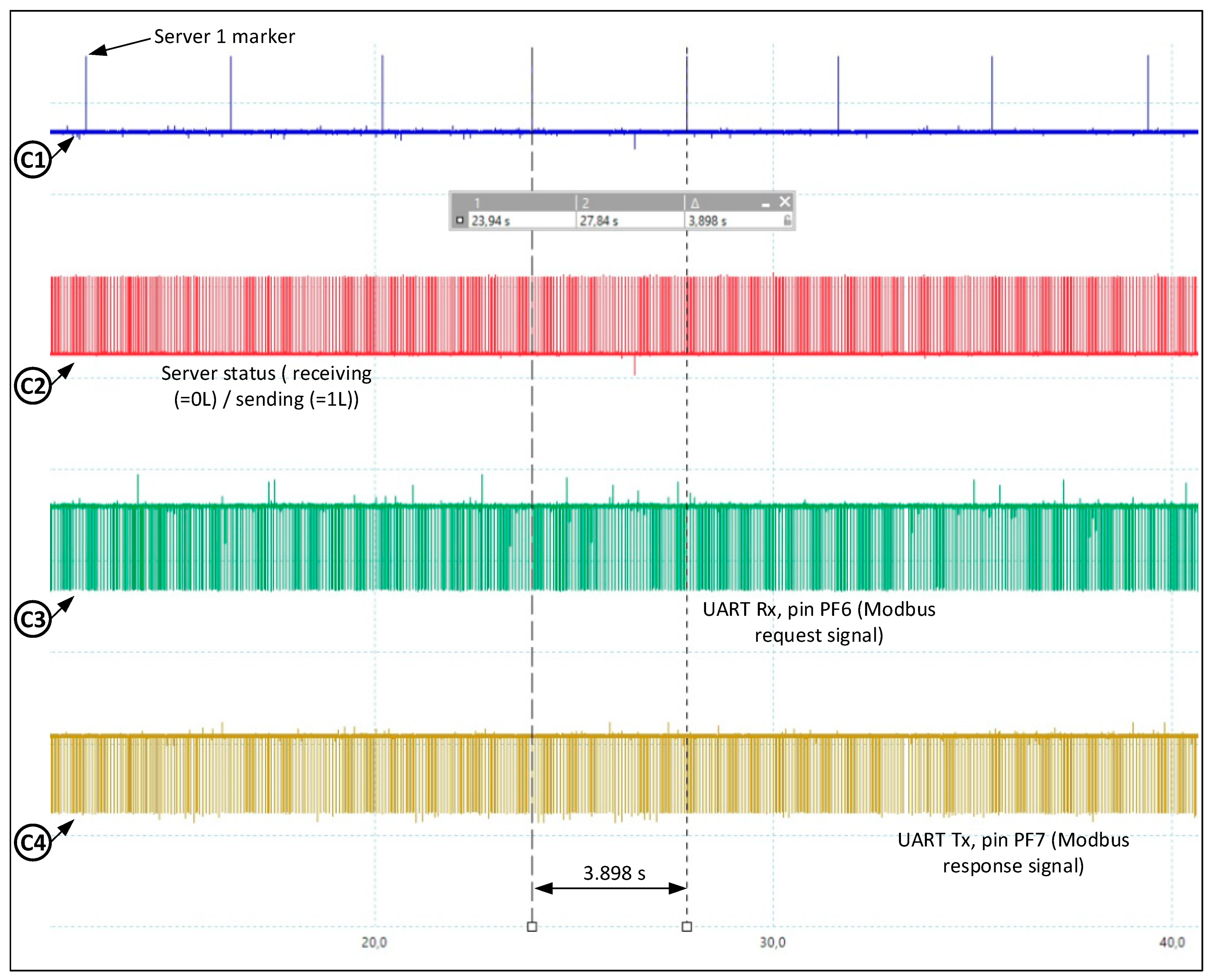
Probe 1 connected to an out pin of the MC (port F, line 8) is used as a spy (indicates the Server_1), probe 2 connected to an out pin of the MC (port F, line 9) is a spy (indicates the send/receive status of Server i) and probe 3 and probe 4 connected to RX (port F, pin 6) and TX (port F, pin 7) monitor the communication on the UART. In the worst case, scattering requires 50 separate read commands with FC03. In this case, we will have 50 read slots contained in one AC. Figure 8a shows the connection parameters for serial bus communication. Figure 8b indicates the ModbusPoll and communication messages for two slaves with addr. 1 and 2 emulated by STM32F7, with the corresponding time stamps. So, from the server with ID 1, a register is read, and from the server with ID 2, a register is written; both registers are at address 0. On the digital oscilloscope captures, the blue color (C1) is assigned to a marker for the beginning of the AC as shown in Figure 9. Note the major difference between a tAC for 50 registers at continuous addresses read with a single command (about 167 ms) and the duration of reading from scattered addresses with one read command for each register (worst case), which is about 3700 ms, i.e., the duration is about 22 times longer.
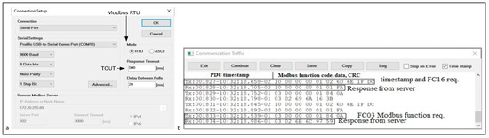
Figure 8.
(a) Connection settings for reading 50 registers separately; (b) Request Modbus FC03 and response FC16 functions with timestamp.
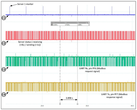
Figure 9.
Acquisition cycle sample (tAC = 3.898s) (Table 2).
In real cases, register grouping can be performed even if some intermediate registers are not of interest. As can be seen in this particular case (Figure 9), the blue slider (cursor signal C1) is assigned as the trigger set at server 1, and cursor signal C2 indicates switching the driver at server i from receive to transmit. The green signal (cursor oscilloscope signal C3) represents the query signal from the client, and the brown signal C4 represents the response signal from server i (the STM32 device emulated by the STM32).
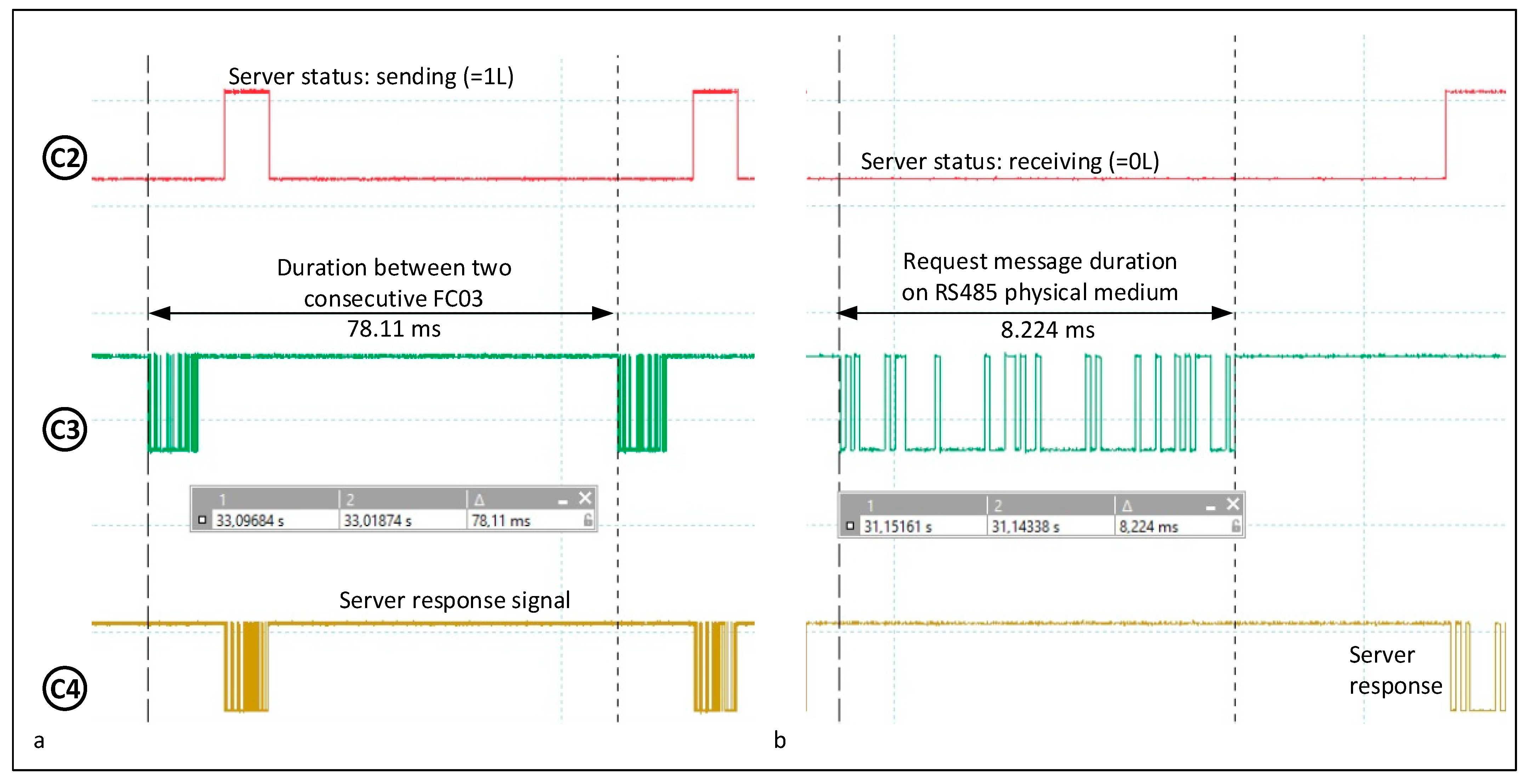
The capture in Figure 10a illustrates the duration between two consecutive reads for different registers. It can be seen that the duration between two consecutive reads of about 80 ms is less than the duration of about 166 ms of a single read of 50 registers, but reads 1 register. We next see how long the transaction takes and how long tAll takes. In these tests, with the other values shown in Table 1, a rarer case was also captured, namely a value of 125 ms. The jitter of a PC application can be variable in large bounds and unpredictable situations may occur. Moreover, the measured values may differ from day to day depending on the PC load. Figure 10b measures the duration of the client request message for the FC03 function. It may be the same as in the test with registers located at consecutive addresses, since it is the same type of request message. Also, in this case, the time is less than the ideal time, so α = 0. The reason is given by the last bits on 1 of the CRC and the stop bit which cannot be easily identified.
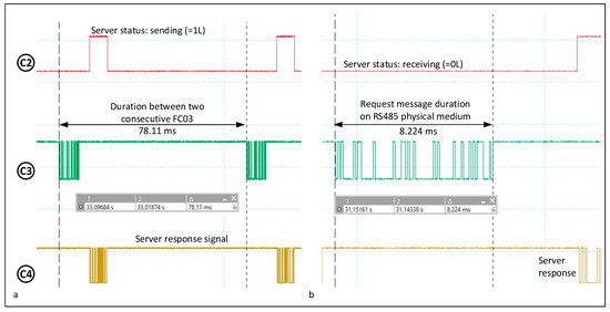
Figure 10.
(a) Duration between two consecutive readings with different client registers; (b) Time duration on RS485 physical medium of the FC03 read request message (Table 2).
A device implementing the Modbus client service can initiate Modbus messaging requests to another device implementing a Modbus server. These requests allow the client to transmit data and/or send commands to a remote device. The Modbus server service allows a device to make all its internal and input/output data available to remote devices in read and write, and allows other commands to be executed. With respect to the Modbus server service, a device implementing the Modbus server service can respond to requests from any Modbus client. In terms of specialized client and server services, there are many devices on the market that combine Modbus functionality together and make it available through easy configuration. One is a sophisticated client known as a scanner. It allows in an optimized way the configuration and repeated read/write execution of field device reads/writes from the Modbus network, with the handling of resends. These are applications of the protocol and provide higher level services. The messages exchanged by Modbus client and server services (client messages and server messages) are defined by a structure called the Application Protocol Data Unit (APDU). The Modbus protocol payload at the application level, also known as the Modbus Protocol Data Unit, consists of two fields, the code and the data fields.
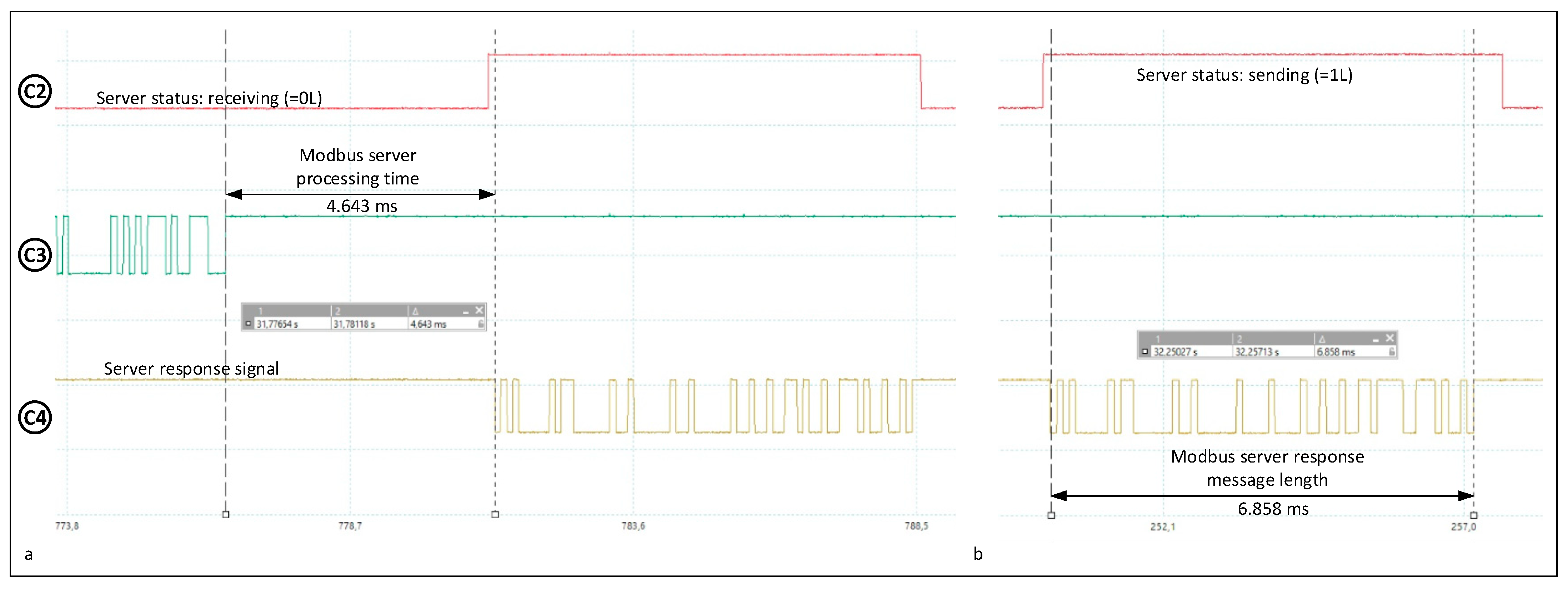
Figure 11a shows the Modbus server processing time measurement. The time consumed by the server station depends on several factors, such as the delay given by switching between tasks, different procedures for processing the request message, preparing the reply message and even the methods used in receiving and transmitting, such as loop waiting, interrupts, DMA and interrupts. As a recommendation, we suggest analyzing each server individually to determine the longest duration of this time using a specialized program. This time is consumed by the server for CRC computation, moving the message to the application, 3.5 characters between messages and a simulated delay that is chosen between 0 ms and 1 ms for constant 1, 1 ms and 2 ms for constant 2, etc. (OsDelay function in the server RTOS). Figure 11b shows the Modbus server response time measurement. The server’s response message has only one register, and its length is 7 bytes.
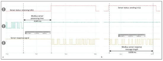
Figure 11.
(a) Modbus server processing time; (b) Modbus server response message duration (Table 3).
As in the case of measuring the response duration at the physical server level with 50 consecutive registers, read errors may occur as well as errors in the digital oscilloscope. In these tests at the physical level, the communication is realized by two microcontroller systems that can use DMA-based serial communication and interrupts. Thus, the server device used to emulate Modbus devices implements the communication at the physical Modbus level. And in this experiment, the length is only one register. The duration of about 7 ms is not 50 times shorter than the message of about 109.5 ms that reads 50 consecutive registers; due to the header, it is only about 25 times shorter.
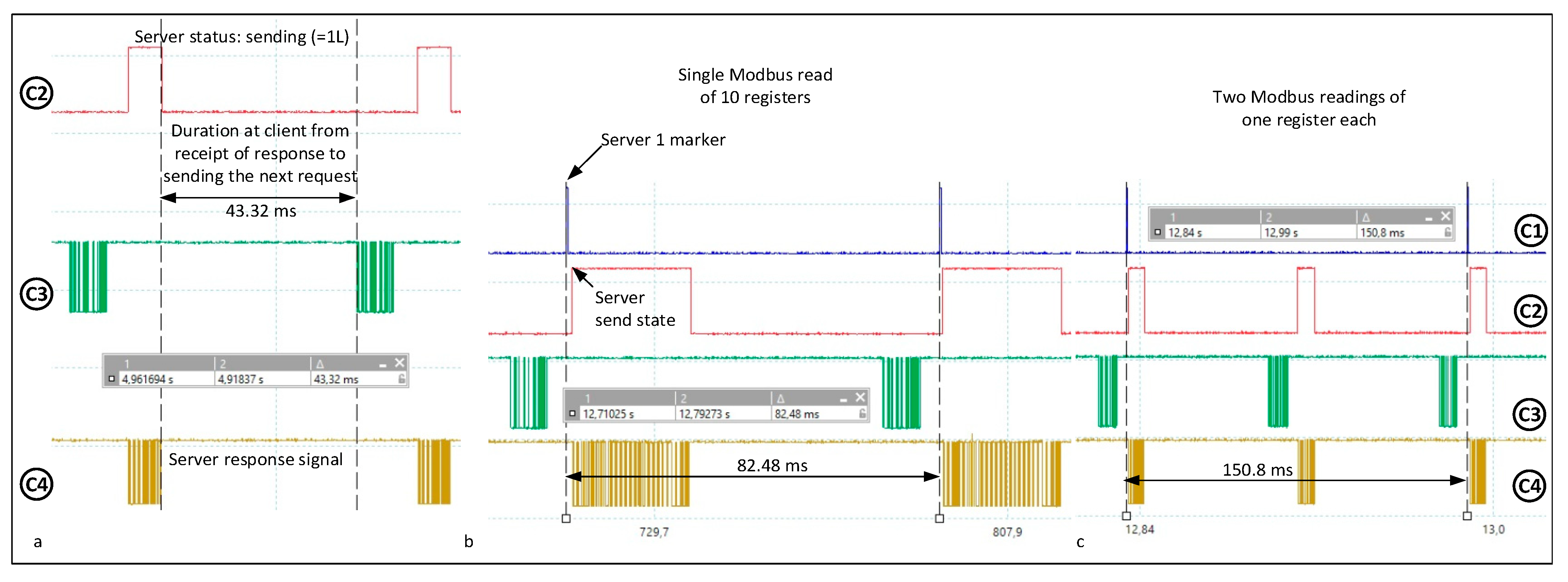
In Figure 12a, we measure the time period for tAll, which is measured directly. Clearly reading multiple registers at consecutive addresses has a shorter duration than reading the same number of registers at scattered addresses. Suppose we want to read two registers, one located at address 1 and the other located at address 10. Based on the mathematical model and the particularization of the Modbus protocol equations correlated with the practical experiments performed, there is the natural question of which solution takes less time. Figure 12b shows a capture with the measured duration for the first solution, namely the solution with a single read of 10 registers, totaling approximately 82.48 ms.
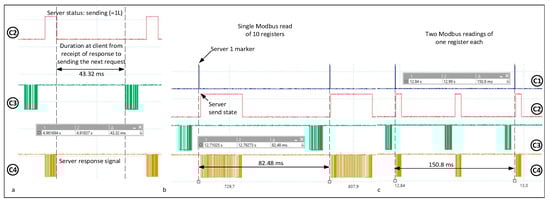
Figure 12.
(a) Duration at the client from receiving the answer to sending the next corresponding query tAll (Table 3); (b) 10-register single-read solution; (c) Version with two readings of one register each.
Figure 12c shows a capture with the measured duration for the second solution (150.8 ms), namely two separate reads, one from address 1 and one from address 10. There are two solutions:
Based on the results obtained from tests with registers located at consecutive addresses in memory, which show that the tAll time is about 43 ms, almost the duration of 40 characters, this solution is of shorter duration. The answer is obvious, the second solution takes almost twice as long. Another question is how far apart the two registers can be from each other in register address. The result we obtained by experiment is shown in Figure 13a.
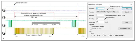
Figure 13.
(a) Determining the maximum distance between register addresses from 1 to 42 (Table 3); (b) Configuring read and write operations for function F03.
4.4. Proposed ModbusE and Its Advantages
The extended Modbus concept is realized at the app level. ModbusE was originally proposed in [10], specifying message structure, AC architecture and BSG acting like a client device. The evaluation of Modbus Extended allows us to propose a new communication message frame, an AC to obtain a deterministic temporal behavior, a specification of Modbus devices and the definition of an architecture for the IIoT integration. Mathematical equations were derived and, based on them, specific timings within a slot of the acquisition cycle were calculated.
Devices attached to the Modbus RS485 bus have to use the common communication rate and implement the Modbus protocol. A 3.3 V USB adapter and a virtual COM on the PC were used for the tests. The tests showed that the constraints are in the PC OS, which causes non-deterministic latencies. Through experiments, it is possible to determine a maximum of these latencies with constant load situations. Ideally, the OS should only be utilized for a particular application. Examples of systems that can exploit the extended Modbus protocol are industrial supervisory processes, systems with medium and high reaction times and IIoT. The testing of ModbusE validated a new communication message structure, a CA for achieving deterministic temporal response behavior. The methods developed in this paper are simple and low-cost solutions, as they enable the integration of existing acquisition adapters with no changes in terms of hardware or software.
Within the ModbusE concept, only the slot no., data and CRC are transferred within a slot, thus adding bandwidth to the communication link. ModbusE messages do not have function code fields and function parameter fields in either the request or response message, and the needed bandwidth is obviously lower than Modbus RTU. For the same payload, the ModbusE message is significantly short compared to the Modbus RTU.
Configuration of data structure and message length info is either setup offline with simple Modbus config tools or performed online by the BSG. In terms of the number of devices, the app was designed to use all user addresses from 1 to 247 (Device ID 0 = broadcast, Device ID 248 ÷ 255 = reserved Device IDs (typically utilized for vendor-specific gateway functions)). Servers that can integrate the extended Modbus design are systems with medium and high response times, manufacturing data acquisition processes and IoT applications. In this work, the delays related to the Modbus communication protocol were evaluated in a PC configuration (client) and in the STM32F7 system (servers) by emulating on the MCU several settings of the server stations and also by sending different messages, each with a distinct number of registers, over Modbus.
5. Discussion
Modbus is an application-level messaging protocol, positioned at the OSI 7 level, that provides client/server communication between devices connected to different types of buses or networks [36,37]. The Internet-connected community can access Modbus using system port 502 on the TCP/IP stack. The de facto serial industry standard since 1979, Modbus continues to enable the communication of millions of automation devices. Today, research into the simple structure of Modbus continues. Schneider-based devices that accept the Modbus FC 100 (0x64) [38] perform a scattered read that permits the reading of non-contiguous registers, with n being in the range of 2 to 100 registers; thus, this operation is not a standard function code and any communication debug support tools will not be programmed to decode the Modbus command. Function codes are the encodings used to indicate requested services, with values in the range of 0x01–0x7F. The value 0x00 is invalid and values in the range of 0x80–0xFF are reserved for the exception handling mechanism, as described below. Successful processing of a function code is signaled by matching the value of the request function code in the same code field in the response. Failure of the processing of a function code is signaled by returning a value obtained from a logical operation of the type OR between 0x80 and the value of the request function code in the same code field of the response. In this case, the returned value is called an exception. The size of the code field is one byte. Exceptions are easy to detect because the code field value will have the most significant bit set.
Modbus Extended brings improvements to the compression of Modbus messages, thus minimizing communication delays and improving data throughput in the RS485 network. The μC validation of the extended Modbus design is based on the new communication message structure, a temporal deterministic behavior thanks to AC, and the proposal of Modbus modules from an embedded architecture in IIoT and smart buildings. Thus, the Modbus Extended design is implemented at the app level defined in [10]. Here, the communication message structure, BSG as client device and data AC with the related issues of embedded microcontroller-based systems were discussed.
For an AC, we can specify the basic time unit as the tick (θ), with the tick size being chosen such that it is supported by all stations in the fieldbus. Regarding the communication paradigm, there are the following architectures: master–slave, producer–consumer and client–server [39]. The AC is composed of slots (S) of length 1, in which l stands for the multiple of a tick θ. In the AC, there can be periodic and aperiodic slots, with the observation that slots can be called periodic even if they transmit aperiodic messages. At least one slot must be aperiodic to be utilized in SDO communication. These slots may have different lengths chosen in the AC configuration. During normal operation, assuming that the length of the slots is fixed, each slot may take a priority defined by PRi.
A particular case is when slots are not defined; PDOs and SDOs are sent through separate queues. If there are SDO objects in the queue, the shared communication channel is alternately allocated among a PDO and an SDO object. PDO objects are placed in a queue and sent via a round-robin algorithm, and SDO objects are stored in an FIFO queue. An AC may have subcycles (AsC). In a network, there are messages characterized by type (SDA, SDN or SRD) and maximum transfer time Mi(type, t), and a message is defined as indivisible. A transaction consists of multiple messages TRi(t), so the transaction is indivisible. A transaction or message is performed in a slot of the AC. Therefore, an incorrect message or communication error cannot increase the slot length. However, the length of the AC will be increased by a fail-safe slot for any emergency situation. The cycle may be provided with an emergency or alarm slot and possibly a synchronization slot. By using Cortex Mx architectures, with STM32F407 at about 49.6% throughput, it can get payload data from the acquisition cycle at 10.5 Mb/s on the serial port, with STM32F746 and 36% payload data from the acquisition cycle at 27 Mb/s on the serial port and with LPC4357 at 58.9% payload data from the AC, which has 2 Cortex M0 and Cortex M4 cores at 11.5 Mb/s on the serial port [40]. Systems that can use the ModbusE protocol are industrial monitoring processes, systems with medium and high response times and IIoT.
6. Conclusions
In industrial control applications, safety protocols are included in addition to the normal CPU workload, providing a range of measures to render communication more robust: sequence codes, CRCs and supplementary acknowledgments, timestamps and timeouts, along with built-in safety monitors and test functions. Hardware features detect residual faults and can typically achieve IEC 61508 safety level 3, making them suitable for emergency applications such as fire, alarm or power plant control. The contributions of this paper refer to the performance analysis based on the duration of the request sent by the client and the processing time to the server, including CRC verification. At the same time, the time period associated with the server’s response to the communication medium was measured, resulting in an approximate prediction of the server’s behavior over time. The performance measured included the FC03 and FC16 functions with the server at address 39 with a significantly longer time for the data read operation of only 25.85 ms compared to 8.206 ms for the write operation, in which case only the header is sent with the response. ModbusE may enhance conventional Modbus in that it does not pass headers, as they are configured at initialization, and it is possible to chain registers located at different in-memory addresses. The behavior of the server is made deterministic by the use of AC, with request–response transactions occurring at a predefined time in the periodic AC. As a conclusion, a real-time control operation is defined as a task or process that runs in an industrial control system or device and meets three criteria: reliable execution of the operation, determination of the operation time and predictable operation results. The deadline is crucial for real-time control operations. When hard real-time process control has to meet the imposed deadline, the resulting errors are fatal or have unintended consequences. It is called soft real-time control when meeting the deadline is not essential. All modern industrial control systems that provide real-time control are defined as real-time control systems. In future research, the LTM2881 driver for RS485 will be used for Modbus communication with different servers, and ModbusE will be integrated into a BIoT application to implement an embedded smart switch embedded device based on the specifications of the ModbusE server.
7. Patents
ModbusE and the built-in smart switch device are based on patent A/00224, 2023 from OSIM.
Author Contributions
Conceptualization, V.G.G., I.Z. and N.C.G.; software, V.G.G., I.Z. and N.C.G.; data curation, V.G.G., I.Z. and N.C.G.; writing—original draft preparation, V.G.G., I.Z. and N.C.G.; writing—review and editing, V.G.G., I.Z. and N.C.G. All authors have read and agreed to the published version of the manuscript.
Funding
This work is also supported by the NetZeRoCities Competence Center, funded by European Union–NextGenerationEU and Romanian Government, under the National Recovery and Resilience Plan for Romania, contract no. 760007/30.12.2022 with the Romanian Ministry of Research, Innovation and Digitalization through the specific research project P2-Sustainable energy and environments.
Data Availability Statement
Data are contained within the article.
Acknowledgments
The authors would like to thank the editor and the anonymous reviewers for reviewing our manuscript.
Conflicts of Interest
The authors declare no conflicts of interest.
References
- Pleinevaux, P.; Decotignie, J.-D. Time critical communication networks: Field buses. IEEE Netw. 1988, 2, 55–63. [Google Scholar] [CrossRef]
- Kiangala, K.S.; Wang, Z. An Effective Communication Prototype for Time-Critical IIoT Manufacturing Factories Using Zero-Loss Redundancy Protocols, Time-Sensitive Networking, and Edge-Computing in an Industry 4.0 Environment. Processes 2021, 9, 2084. [Google Scholar] [CrossRef]
- Reyes, N.A.; Cerrato, H.I. Modbus TCP Bridging for Interconnecting Non-Compatible Devices in the Energy Sector Using Node-RED and Edge Computing. In Proceedings of the 2023 IEEE 41st Central America and Panama Convention (CONCAPAN XLI), Tegucigalpa, Honduras, 8–10 November 2023; pp. 1–4. [Google Scholar] [CrossRef]
- Rodriguez-Perez, N.; Domingo, J.M.; Lopez, G.L.; Stojanovic, V. Scalability Evaluation of a Modbus TCP Control and Moni-toring System for Distributed Energy Resources. In Proceedings of the 2022 IEEE PES Innovative Smart Grid Technologies Conference Europe (ISGT-Europe), Novi Sad, Serbia, 10–12 October 2022; pp. 1–6. [Google Scholar] [CrossRef]
- Biondani, F.; Cheng, D.S.; Fummi, F. Adopting OPC UA for Efficient and Secure Firmware Transmission in Industry 4.0 Scenarios. In Proceedings of the 2024 IEEE 33rd International Symposium on Industrial Electronics (ISIE), Ulsan, Republic of Korea, 18–21 June 2024; pp. 1–6. [Google Scholar] [CrossRef]
- Zurawski, R. The Industrial Communication Technology Handbook; CRC Press: Boca Raton, FL, USA, 2015; ISBN-13:978-1-4822-0733-0. [Google Scholar]
- Kohútka, L.; Stopjaková, V. Extension of hardware-accelerated real-time task schedulers for support of quad-core processors. In Proceedings of the 2017 5th IEEE Workshop on Advances in Information, Electronic and Electrical Engineering (AIEEE), Riga, Latvia, 24–25 November 2017; pp. 1–6. [Google Scholar] [CrossRef]
- Available online: www.modbus.org (accessed on 22 July 2022).
- Lazaridis, G.; Drosou, A.; Chatzimisios, P.; Tzovaras, D. Securing Modbus TCP Communications in I4.0: A Penetration Test-ing Approach Using OpenPLC and Factory IO. In Proceedings of the 2023 IEEE Conference on Standards for Communica-tions and Networking (CSCN), Munich, Germany, 6–8 November 2023; pp. 265–270. [Google Scholar] [CrossRef]
- Găitan, V.G.; Găitan, N.C.; Ungurean, I. A flexible acquisition cycle for incompletely defined fieldbus protocols. ISA Trans. 2014, 53, 776–786. [Google Scholar] [CrossRef] [PubMed]
- Zagan, I.; Găitan, V.G. Enhancing the Modbus Communication Protocol to Minimize Acquisition Times Based on an STM32-Embedded Device. Mathematics 2022, 10, 4686. [Google Scholar] [CrossRef]
- Găitan, N.C.; Zagan, I.; Găitan, V.G. Proposed Modbus Extension Protocol and Real-Time Communication Timing Requirements for Distributed Embedded Systems. Technologies 2024, 12, 187. [Google Scholar] [CrossRef]
- Găitan, V.G.; Zagan, I. Modbus Protocol Performance Analysis in a Variable Configuration of the Physical Fieldbus Architecture. IEEE Access 2022, 10, 123942–123955. [Google Scholar] [CrossRef]
- Găitan, V.G.; Zagan, I. Modbus Extension Server Implementation for BIoT-Enabled Smart Switch Embedded System Device. Sensors 2024, 24, 475. [Google Scholar] [CrossRef] [PubMed]
- Kurose, J.F.; Ross, K.W. Computer Networking: A Top-Down Approach; Addision Wesley: Boston, MA, USA, 2017; ISBN-10: 1-292-15359-8, ISBN-13: 978-1-292-15359-9. [Google Scholar]
- Jiang, M.; Wu, G.; Qiao, W.; Chen, X.; Fang, J.; Xie, M. Design of Profibus-DP module based on APC3 chip. In Proceedings of the 2024 7th International Conference on Energy, Electrical and Power Engineering (CEEPE), Yangzhou, China, 26–28 April 2024; pp. 1260–1264. [Google Scholar] [CrossRef]
- Actuator Sensor Interface. Available online: https://www.as-interface.net/ (accessed on 20 July 2024).
- Ghosh, T.; Bagui, S.; Bagui, S.; Kadzis, M.; Bare, J. Anomaly Detection for Modbus over TCP in Control Systems Using Entropy and Classification-Based Analysis. J. Cybersecur. Priv. 2023, 3, 895–913. [Google Scholar] [CrossRef]
- Tovar, E.; Vasques, F.; Burns, A. Adding local priority-based dispatching mechanisms to P-NET networks: A fixed priority approach. In Proceedings of the 11th Euromicro Conference on Real-Time Systems. Euromicro RTS’99, York, UK, 9–11 June 1999; pp. 175–184. [Google Scholar] [CrossRef]
- Nawrocki, G.J.; Arnold, N.D.; Hoffberg, M.G.; Winans, J.R.; Benes, S.J. An I/O subnet for the APS control system-the BITBUS universal gateway. In Proceedings of the International Conference on Particle Accelerators, Washington, DC, USA, 17–20 May 1993; Volume 3, pp. 1957–1959. [Google Scholar] [CrossRef]
- Feng, T.; Liu, C.; Gong, X.; Lu, Y. Security Analysis and Enhancement of INTERBUS Protocol in ICS Based on Colored Petri Net. Information 2023, 14, 589. [Google Scholar] [CrossRef]
- Zhou, Y.; Yu, H.; Wang, T.; Wang, Z.; Wu, C. DSPN model and performance analysis of WorldFIP MAC sub-layer. In Proceedings of the 30th Annual Conference of IEEE Industrial Electronics Society, 2004. IECON 2004, Busan, Republic of Korea, 2–6 November 2004; Volume 3, pp. 2552–2555. [Google Scholar] [CrossRef]
- Peserico, G.; Morato, A.; Tramarin, F.; Vitturi, S. Functional Safety Networks and Protocols in the Industrial Internet of Things Era. Sensors 2021, 21, 6073. [Google Scholar] [CrossRef]
- Biegacki, S.; VanGompel, D. The application of DeviceNet in process control. ISA Trans. 1996, 35, 169–176. [Google Scholar] [CrossRef]
- Hartley, Z.K.J.; Lind, R.J.; Pound, M.P.; French, A.P. Domain Targeted Synthetic Plant Style Transfer using Stable Diffusion, LoRA and ControlNet. In Proceedings of the 2024 IEEE/CVF Conference on Computer Vision and Pattern Recognition Workshops (CVPRW), Seattle, WA, USA, 17–18 June 2024; pp. 5375–5383. [Google Scholar] [CrossRef]
- Huang, X.; Li, J. The Application of LonWorks in the Building Air Conditioner Intelligent Control System. In Proceedings of the 2012 4th International Conference on Intelligent Human-Machine Systems and Cybernetics, Nanchang, China, 26–27 August 2012; pp. 205–207. [Google Scholar] [CrossRef]
- Yue, G. Design of Intelligent Monitoring and Control System Based on Modbus. In Proceedings of the 2020 5th International Conference on Communication, Image and Signal Processing (CCISP), Chengdu, China, 13–15 November 2020; pp. 149–153. [Google Scholar] [CrossRef]
- Siddavatam, I.A.; Parekh, S.; Shah, T.; Kazi, F. Testing and validation of Modbus/TCP protocol for secure SCADA communication In CPS using formal methods. Scalable Comput. Pract. Exp. 2017, 18, 313–330. [Google Scholar] [CrossRef]
- Elamanov, S.; Son, H.; Flynn, B.; Ki Yoo, S.; Dilshad, N.; Song, J.S. Interworking between Modbus and internet of things platform for industrial services. Digit. Commun. Netw. 2022, 10, 461–471. [Google Scholar] [CrossRef]
- Ergan, A.F.; Sarıoğlu, K. Design and Application of a Novel Dimmable Lighting Control Unit with Active Power Measurement via KNX Protocol. In Proceedings of the 2021 13th International Conference on Electrical and Electronics Engineering (ELECO), Bursa, Turkey, 25–27 November 2021; pp. 555–559. [Google Scholar] [CrossRef]
- Wang, S.; Ouyang, J.; Li, D.; Liu, C. An Integrated Industrial Ethernet Solution for the Implementation of Smart Factory. IEEE Access 2017, 5, 25455–25462. [Google Scholar] [CrossRef]
- Nguyen, T.; Huynh, T. Design and implementation of modbus slave based on ARM platform and FreeRTOS environment. In Proceedings of the International Conference on Advanced Technologies for Communications (ATC), Ho Chi Minh City, Vietnam, 14–16 October 2015; pp. 462–467. [Google Scholar]
- Daniel Flow Products, Modbus Communications Model 2500, Part Number: 3-9000-545 Revision D. November 1992. Available online: www.emerson.com/documents/automation/daniel-modbus-communications-model-2500-manual-en-43890.pdf (accessed on 22 July 2024).
- Modbus Application Protocol Specification, V1.1b, Modbus-IDA. 2006. Available online: www.modbus.org/docs/Modbus_Application_Protocol_V1_1b.pdf (accessed on 22 July 2022).
- 32F746GDISCOVERY: Discovery kit with STM32F746NG MCU, DB2582-Rev 3-December 2019. Available online: https://www.st.com (accessed on 20 July 2024).
- Katulić, F.; Sumina, D.; Groš, S.; Erceg, I. Protecting Modbus/TCP-Based Industrial Automation and Control Systems Using Message Authentication Codes. IEEE Access 2023, 11, 47007–47023. [Google Scholar] [CrossRef]
- Felser, M. Real-time Ethernet—Industry prospective. Proc. IEEE 2005, 93, 1118–1129. [Google Scholar] [CrossRef]
- Modbus Scattered Holding Register Read Function. Available online: https://www.se.com/in/en/faqs/FAQ000241252/ (accessed on 2 October 2024).
- Li, X.; Li, D.; Wan, J.; Vasilakos, A.V.; Lai, C.F.; Wang, S. A review of industrial wireless networks in the context of Industry 4.0. Wireless Netw. 2017, 23, 23–41. [Google Scholar] [CrossRef]
- Ventuneac, C.; Gaitan, V.G. Industrial Internet of Things Gateway with OPC UA Based on Sitara AM335X with ModbusE Acquisition Cycle Performance Analysis. Sensors 2024, 24, 2072. [Google Scholar] [CrossRef]

Disclaimer/Publisher’s Note: The statements, opinions and data contained in all publications are solely those of the individual author(s) and contributor(s) and not of MDPI and/or the editor(s). MDPI and/or the editor(s) disclaim responsibility for any injury to people or property resulting from any ideas, methods, instructions or products referred to in the content. |
© 2025 by the authors. Licensee MDPI, Basel, Switzerland. This article is an open access article distributed under the terms and conditions of the Creative Commons Attribution (CC BY) license (https://creativecommons.org/licenses/by/4.0/).